EP2143599A1 - Antitheft system - Google Patents
Antitheft system Download PDFInfo
- Publication number
- EP2143599A1 EP2143599A1 EP20090165032 EP09165032A EP2143599A1 EP 2143599 A1 EP2143599 A1 EP 2143599A1 EP 20090165032 EP20090165032 EP 20090165032 EP 09165032 A EP09165032 A EP 09165032A EP 2143599 A1 EP2143599 A1 EP 2143599A1
- Authority
- EP
- European Patent Office
- Prior art keywords
- key
- engine
- equipment
- operator
- operating power
- Prior art date
- Legal status (The legal status is an assumption and is not a legal conclusion. Google has not performed a legal analysis and makes no representation as to the accuracy of the status listed.)
- Granted
Links
- 239000007858 starting material Substances 0.000 claims abstract description 19
- 238000002485 combustion reaction Methods 0.000 claims abstract description 13
- 238000004891 communication Methods 0.000 description 10
- 230000004044 response Effects 0.000 description 5
- 230000005540 biological transmission Effects 0.000 description 4
- 244000025254 Cannabis sativa Species 0.000 description 3
- 238000010586 diagram Methods 0.000 description 2
- 238000006073 displacement reaction Methods 0.000 description 2
- 230000000694 effects Effects 0.000 description 2
- 239000000446 fuel Substances 0.000 description 2
- 230000003213 activating effect Effects 0.000 description 1
- 230000004913 activation Effects 0.000 description 1
- 230000002411 adverse Effects 0.000 description 1
- 230000003247 decreasing effect Effects 0.000 description 1
- 230000005674 electromagnetic induction Effects 0.000 description 1
- 239000002828 fuel tank Substances 0.000 description 1
- 239000003502 gasoline Substances 0.000 description 1
- 238000005007 materials handling Methods 0.000 description 1
- 230000007246 mechanism Effects 0.000 description 1
- 238000000034 method Methods 0.000 description 1
- 239000000203 mixture Substances 0.000 description 1
- 238000010248 power generation Methods 0.000 description 1
- 230000008569 process Effects 0.000 description 1
- 239000011347 resin Substances 0.000 description 1
- 229920005989 resin Polymers 0.000 description 1
- 230000001360 synchronised effect Effects 0.000 description 1
- 238000011144 upstream manufacturing Methods 0.000 description 1
Images




Classifications
-
- B—PERFORMING OPERATIONS; TRANSPORTING
- B60—VEHICLES IN GENERAL
- B60R—VEHICLES, VEHICLE FITTINGS, OR VEHICLE PARTS, NOT OTHERWISE PROVIDED FOR
- B60R25/00—Fittings or systems for preventing or indicating unauthorised use or theft of vehicles
- B60R25/01—Fittings or systems for preventing or indicating unauthorised use or theft of vehicles operating on vehicle systems or fittings, e.g. on doors, seats or windscreens
- B60R25/04—Fittings or systems for preventing or indicating unauthorised use or theft of vehicles operating on vehicle systems or fittings, e.g. on doors, seats or windscreens operating on the propulsion system, e.g. engine or drive motor
-
- A—HUMAN NECESSITIES
- A01—AGRICULTURE; FORESTRY; ANIMAL HUSBANDRY; HUNTING; TRAPPING; FISHING
- A01D—HARVESTING; MOWING
- A01D34/00—Mowers; Mowing apparatus of harvesters
- A01D34/01—Mowers; Mowing apparatus of harvesters characterised by features relating to the type of cutting apparatus
- A01D34/412—Mowers; Mowing apparatus of harvesters characterised by features relating to the type of cutting apparatus having rotating cutters
- A01D34/63—Mowers; Mowing apparatus of harvesters characterised by features relating to the type of cutting apparatus having rotating cutters having cutters rotating about a vertical axis
- A01D34/82—Other details
-
- B—PERFORMING OPERATIONS; TRANSPORTING
- B60—VEHICLES IN GENERAL
- B60R—VEHICLES, VEHICLE FITTINGS, OR VEHICLE PARTS, NOT OTHERWISE PROVIDED FOR
- B60R25/00—Fittings or systems for preventing or indicating unauthorised use or theft of vehicles
- B60R25/20—Means to switch the anti-theft system on or off
- B60R25/24—Means to switch the anti-theft system on or off using electronic identifiers containing a code not memorised by the user
-
- B—PERFORMING OPERATIONS; TRANSPORTING
- B60—VEHICLES IN GENERAL
- B60R—VEHICLES, VEHICLE FITTINGS, OR VEHICLE PARTS, NOT OTHERWISE PROVIDED FOR
- B60R2325/00—Indexing scheme relating to vehicle anti-theft devices
- B60R2325/30—Vehicles applying the vehicle anti-theft devices
- B60R2325/308—Industrial vehicles
Definitions
- This invention relates to an antitheft system, particularly to an antitheft system of equipment, such as an operating machine or moving object, which has a general-purpose internal combustion engine equipped with a power generator that supplies operating power in response to operator's manipulation of a recoil starter.
- Such the equipment constituted of the moving object or operating machine e.g., a lawnmower
- a general-purpose internal combustion engine equipped with a power generator that supplies operating power in response to operator's manipulation of a recoil starter.
- a recoil starter e.g., a lawnmower
- the aforementioned antitheft system configured to be supplied with operating power from a battery cannot be applied.
- a battery for the system could be newly provided to the equipment, it adversely affects size of the entire equipment and cost.
- An object of this invention is therefore to overcome the aforesaid problem by providing an antitheft system that can be installed in battery-less equipment and ensures to prevent the equipment from theft.
- this invention provides a system for preventing an equipment from theft, comprising: an internal combustion engine that is mounted on the equipment and is equipped with a generator that generates electric operating power when the engine is operated; a recoil starter that is installed on the engine to be manipulatable by an operator to operate the engine; an electronic key that is adapted to be carried by the operator of the equipment and stores authenticating data for identifying the operator who carries the electronic key; and an authenticator that is installed at the equipment and performs authentication check as to whether the electronic key is an authorized key using stored key-checking data, when the authenticating data is outputted from the electronic key; wherein the authenticator performs the authentication check when the electric operating power is supplied from the generator.
- FIG. 1 is an overall view of an antitheft system according to an embodiment of this invention, which is installed in a lawnmower, and FIG. 2 is a plan view of the lawnmower.
- the reference numeral 10 indicates the lawnmower (operating machine; equipment).
- the lawnmower 10 is a non-riding self-propelled lawnmower with two front wheels 12F and two rear wheels 12R (a total of four wheels), and a handlebar 14.
- a general-purpose internal combustion engine (hereinafter called "engine”) 18 is installed beneath an engine cover 16 on a frame mounted on the four wheels 12F and 12R.
- the engine 18 is equipped with a recoil starter 20 installed to be manipulatable by the operator P (shown only in FIG. 1 ).
- a crankshaft 22 of the engine 18 is connected to a rear wheel drive axle 26 via a belt 24, as shown in FIG. 1 .
- the drive axle 26 is connected to the rear wheels 12R via a gear mechanism 28.
- a rear wheel electromagnetic clutch 30 is disposed in the middle of the drive axle 26, and the clutch 30 cuts off the transmission of engine output to the rear wheels 12R.
- a grass-cutting blade 32 is mounted on the distal end of the crankshaft 22.
- a blade electromagnetic clutch 34 is disposed between the blade 32 and the belt 24 in the crankshaft 22, and the clutch 34 cuts off the transmission of engine output to the blade 32.
- a grass bag 36 is installed in the rear part of the lawnmower 10, so that the grass cut by the blade 32 is collected in the grass bag 36.
- a drive lever 38 and a drive switch 40 which produces an ON signal when the drive lever 38 is moved to tilt forward by the operator P in the traveling direction of the lawnmower 10 are installed near the distal end of the handlebar 14.
- a blade switch 42 is installed on the drive lever 38. The blade switch 42 produces an ON signal when pressed once by the operator P, and terminates producing the ON signal when pressed again.
- FIG. 3 is an enlarged cross-sectional view of the engine 18 shown in FIG. 1 .
- the engine 18 has a cylinder 46, and a piston 48 is accommodated therein to reciprocate.
- An air intake valve 52 and an exhaust valve 54 are disposed at a position facing a combustion chamber 50 of the engine 18 to open and close the connection between the combustion chamber 50 and an intake passage 56 or exhaust passage 58.
- the engine 18 specifically comprises an air-cooled, four-cycle, single cylinder OHV engine, and has a displacement of, for example, 163cc.
- the piston 48 is coupled with the crankshaft 22.
- One end of the crankshaft 22 is attached with a flywheel 60 and the distal end of the flywheel 60 is attached with the recoil starter 20.
- the blade 32 is installed on the other end of the crankshaft 22 via the blade electromagnetic clutch 34.
- a magneto coil (alternator; generator) 66 is mounted on the side of a crankcase 64 so as to face the permanent magnets 62.
- the crankshaft 22 is rotated by the operator's manipulation of the recoil starter 20 or reciprocal motion of the piston 48, the magneto coil 66 generates output (alternating current) in synchronous with the rotation.
- the alternating current generated by the magneto coil 66 is converted to direct current by a processing circuit (not shown) to be supplied as operating power to a control ECU, authentication ECU (explained later), ignition circuit (not shown) and the like.
- the magneto coil 66 outputs (generates) power sufficient both for starting the engine 18 and for operating the authentication ECU, etc.
- the engine 18 can be started by the recoil starter 20, so it is not equipped with a battery. In other words, it is a battery-less type general purpose internal combustion engine.
- a throttle body 68 is installed in the intake passage 56.
- a throttle valve 70 and an electric motor 72 for driving the throttle valve 70 are accommodated in the throttle body 68.
- a carburetor assembly (not shown) is provided at a location upstream of the throttle valve 70 and injects gasoline fuel supplied from a fuel tank (indicated by reference numeral 74 in FIGs. 1 and 2 ). The resulting air-fuel mixture is drawn into the combustion chamber 50 through the throttle valve 70, intake passage 56 and air intake valve 52.
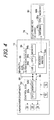
- FIG. 4 is a block diagram showing the configuration of the antitheft system for the lawnmower 10 on which the engine 18 is mounted.
- the antitheft system is assigned by the reference numeral 76 in FIG. 4 .
- the system 76 is equipped with an electronic key 80 that stores authenticating data, a control ECU (second ECU) 82 that is installed in the lawnmower 10 and controls the operation of the engine 18 and other components, and an authentication ECU (first ECU) 84 that is installed in the lawnmower 10 for authenticating the key 80.
- the ECUs 82, 84 are both disposed at suitable locations in the lawnmower 10, i.e., inside the engine cover 16 near the recoil starter 20.
- the control ECU 82 comprises a microcomputer (second microcomputer) having a CPU 82a, memory (EEPROM non-volatile memory) 82b and the like.
- the control ECU 82 is inputted with a drive command (ON signal) from the operator P using the drive switch 40 and with a blade operation command (ON signal) from the operator P using the blade switch 42.
- the control ECU 82 engages the rear wheel magnetic clutch 30 to transmit the rotational output of the engine 18 to the rear wheels 12R, whereby the lawnmower 10 is self-propelled.
- the control ECU 82 engages the blade magnetic clutch 34 to transmit the rotational output of the engine 18 to the blade 32, thereby rotating the blade 32 to rotate the blade 32 (enable mowing).
- the control ECU 82 is further inputted with outputs of a throttle position sensor, crank angle sensor (neither shown), etc. Based on the inputted outputs, the ECU 82 operates the motor 72 of the throttle valve 70 to control speed Ne of the engine 18 (so as to be kept at predetermined speed, for example). However, since the control is not directly related to this invention, it will not be explained here.
- the authentication ECU 84 comprises, similarly to the control ECU 82, a microcomputer (first microcomputer) having a CPU 84a, a memory (EEPROM) 84b for storing key-checking data (explained later) and other components.
- the authentication ECU 84 is further equipped with a reader/writer 84c for reading from the key 80 authenticating data stored therein and performing other operation and with an LED (light-emitting diode; signal lamp; information device) 84d for informing the operator P of the result of electronic key authentication (pass/fail).
- the authentication ECU 84 is connected for communication with the control ECU 82 through a serial communication line 86.
- the ECUs 82, 84 are connected to the magneto coil 66 through a power line 90 to be supplied with operating power generated by the magneto coil 66.
- the key 80 is a contact-less IC (integrated circuit) card equipped with a CPU 80a, a non-volatile memory 80b for storing authenticating data (i.e., identification data (user ID) for identifying the operator P who carries the key 80 and identification information (product ID) for identifying the model, etc., of the lawnmower 10), and an antenna 80c for exchange (input/output) with the reader/writer 84c of authenticating data, etc., by short-distance wireless communication (RFID: Radio Frequency Identification).
- the IC card constituting the key 80 is a card made of resin and houses the CPU 80a and other components in its interior. As shown in FIG 1 , it is made portable to be carried by the operator P.
- the key 80 Upon receipt of the radio wave transmitted by the reader/writer 84c, the key 80 generates power by electromagnetic induction of a built-in coil (not shown), thereby activating the CPU 80a and the like.
- the key 80 is not equipped with a battery or other internal power supply source but is supplied with operating power induced by the radio wave from the reader/writer 84c.
- the CPU 80a of the key 80 Upon being supplied with power, the CPU 80a of the key 80 outputs the authenticating data stored in the memory 80b to the reader/writer 84c through the antenna 80c.
- the authentication ECU 84 uses the key-checking data stored in the memory 84b to perform an authentication check to determine whether the key 80 is an authorized key.
- the key-checking data is identical to the authenticating data such as the user ID and product ID.
- the ECU 84 performs the authentication by comparing the authenticating data in the key 80 with the key-checking data. Specifically, the authenticating data and the key-checking data are compared each other to determine whether they are identical, and the key 80 moved to the reader/writer 84c is discriminated to be an authorized key for the lawnmower 10 if they are the same and not to be an authorized key if they do not match.
- the key 80 is thus a contact-less (wireless) IC card that can input/output (communicate) authenticating data and the like when the operator P merely moves it to, but out of contact with, the reader/writer 84c of the authentication ECU 84.
- FIG. 5 is a flowchart showing the operation of the system 76, specifically the sequence of operations of authentication ECU 84 thereof. The illustrated program is executed only once when the engine 18 is started.
- the program begins in S10, in which the initial check (operation check) of the microcomputer constituting the authentication ECU 84 is conducted. At this time, the initial check of the microcomputer constituting the control ECU 82 is not conducted. As a result, an authentication check can be started early and it shortens the processing time of the authentication ECU 84.
- the program proceeds to S12, in which the reader/writer 84c outputs radio wave to the key 80 to supply operating power, and to S 14, in which the authentication of the key 80 is performed using the authenticating data outputted from the key 80 and key-checking data.
- the authentication EUC 84 performs the authentication check when the recoil starter 20 is manipulated by the operator P and the magneto coil 66 supplies operating power to the ECU 84.
- the program proceeds to S16, in which it is determined whether the key 80 was found to be an authorized key for the lawnmower 10. When the result is affirmative, the program proceeds to S 18, in which a signal enabling to execute the initial check (operation check) of the microcomputer of the control ECU 82 is sent to the control EUC 82, whereafter the program is terminated. Specifically, the control ECU 82 conducts the initial check of its microcomputer upon being inputted with the signal from the authentication ECU 84. Thus, the control ECU 82 conducts the initial check after the operating power is supplied and the authentication check is performed by the authentication ECU 84.
- FIG. 6 is a time chart for explaining the operation of FIG. 5 flowchart.
- the engine 18 is started, while the magneto coil 66 generates and outputs operating power.
- the operating power is supplied to the authentication ECU 84, etc., at a time t2, the authentication ECU 84 is activated and the program of FIG. 5 is started, i.e., the initial check of the microcomputer of the ECU 84 is conducted (S10).
- the authentication check is performed (S12 to S16) and the key authentication is completed at a time t4.
- the key 80 is authenticated to be the authorized key
- the engine 18 is operated normally (S20). Specifically, as indicated by a solid line in FIG. 6 , the operating power is continuously supplied from the magneto coil 66 to the engine 18, ECUs 84, 82 and other components, while the engine speed Ne is kept at a predetermined value.
- the operation of the engine 18 is terminated by ignition cut-off (S24). Specifically, as indicated by an imaginary line in FIG. 6 , the engine speed Ne is gradually decreased to stop the engine 18 and, along therewith, the magneto coil 66 is stopped supplying the operating power to the ECUs 84, 82, etc. Accordingly, the operations of the ECUs 84, 82 are terminated.
- the operation of the engine 18 is terminated in S24 of FIG. 5 (the time t4 of FIG. 6 ) when the key 80 is not the authorized key.
- this arrangement makes lawn mowing impossible but allows the lawnmower 10 to be driven at low speed, thus providing a way to deal with cases where the operator P lost the key 80.
- this embodiment is configured to have a system (76) for preventing an equipment (10) from theft, characterized by: an internal combustion engine (18) that is mounted on the equipment and is equipped with a generator (magneto coil 66) that generates electric operating power when the engine is operated; a recoil starter (20) that is installed on the engine to be manipulatable by an operator to operate the engine; an electronic key (80) that is adapted to be carried by an operator of the equipment and stores authenticating data for identifying the operator who carries the electronic key; and an authenticator (84, S14, S16) that is installed at the equipment and performs authentication check as to whether the electronic key is an authorized key using stored key-checking data, when the authenticating data is outputted from the electronic key; wherein the authenticator performs the authentication check when the electric operating power is supplied from the generator.
- an internal combustion engine that is mounted on the equipment and is equipped with a generator (magneto coil 66) that generates electric operating power when the engine is operated
- a recoil starter (20) that is
- the authentication ECU 84 is configured to perform authentication as to whether the key 80 is the authorized key not with supply of operating power from a battery but with that from the magneto coil 66 that operates in response to the operator's manipulation of the recoil starter 20, the authentication ECU 84 can be operated (installed) in the battery-less lawnmower (equipment) 10, thereby ensuring to prevent the lawnmower 10 from theft.
- the authenticator (84) terminates operation of the engine, when the electronic key (80) is not authenticated to be an authorized key (S16, S24). Specifically, although the engine 18 is started once in response to the operator's manipulation of the recoil starter 20, it is immediately stopped when the key 80 is found to be not the authorized key. Therefore, the lawnmower 10 can be reliably prevented from theft.
- the generator (66) generates the electric operating power for the authenticator (84) to perform the authentication check and for the engine (18) to be started. With this, it becomes possible to ensure power (operating power) needed for starting the engine 18 and operating the authentication ECU 84, thereby enabling to reliably operate the authentication ECU 84.
- the authenticator (84) comprises a first electronic control (84) unit having a first microcomputer (84a), and the first electronic control unit (84) conducts an operation check of the first microcomputer and then performs the authentication check, when the electric operating power is supplied from the generator.
- the initial check of the microcomputer which is not necessary for the key authentication i.e., the microcomputer of the control ECU 82
- the processing time of the authentication ECU 84 can be shortened to make it possible to complete the authentication within a limited operating power supplying period.
- the system further includes: an engine controller (82) that controls operation of the engine and comprises a second electronic control unit having a second microcomputer (82a); and the second electronic control unit (82) conducts an operation check of the second microcomputer, when the electric operating power is supplied from the generator after the authenticator performs the authentication check.
- an engine controller (82) that controls operation of the engine and comprises a second electronic control unit having a second microcomputer (82a); and the second electronic control unit (82) conducts an operation check of the second microcomputer, when the electric operating power is supplied from the generator after the authenticator performs the authentication check.
- the system further includes: an informer that informs the operator, when the electronic key is not authenticated to be an authorized key. With this, it becomes possible to let the operator P recognize that the key 80 was found to be not the authorized key.
- the equipment comprises an operating machine or a moving object. More specifically, the equipment comprises a lawnmower (10).
- the electronic key (80) comprises an IC card.
- the embodiment is explained taking an operating machine, i.e., the lawnmower 10 as an example of the equipment having the system 76, it can be other kinds of equipment of battery-less type having a generator (magneto coil) that supplies operating power in response to the operator's manipulation of the recoil starter.
- a generator magnetic coil
- it can be machines such as cultivators, generators, snow removal machines and materials handling machines, and moving objects such as four-wheeled vehicles, two-wheeled vehicles and small electric vehicles.
- the key 80 and the reader/writer 84c of the authentication ECU 84 are configured to exchange data using short-distance RFID wireless communication, it is alternatively possible to exchange data via another type of wireless communication means or wired communication means.
- piston displacement of the engine 18 was specified, the specified value is non-limiting example.
- a system for preventing an equipment such as lawnmower from theft there are equipped with an internal combustion engine (18) that is mounted on the equipment and is equipped with a generator (66) that generates electric operating power when the engine is operated, a recoil starter to be manipulatable by an operator to operate the engine, an electronic key (80) that is adapted to be carried by the operator and stores authenticating data for identifying the operator who carries the electronic key; and an authenticator (84) that is installed at the equipment and performs authentication check as to whether the electronic key is an authorized key using stored key-checking data, when the authenticating data is outputted from the electronic key.
- the authenticator performs the authentication check when the electric operating power is supplied from the generator, thereby enabling to be installed in battery-less equipment and ensure to prevent the equipment from theft.
Landscapes
- Engineering & Computer Science (AREA)
- Mechanical Engineering (AREA)
- Life Sciences & Earth Sciences (AREA)
- Environmental Sciences (AREA)
- Combined Controls Of Internal Combustion Engines (AREA)
- Lock And Its Accessories (AREA)
- Harvester Elements (AREA)
- Control Of Vehicle Engines Or Engines For Specific Uses (AREA)
Abstract
Description
- This invention relates to an antitheft system, particularly to an antitheft system of equipment, such as an operating machine or moving object, which has a general-purpose internal combustion engine equipped with a power generator that supplies operating power in response to operator's manipulation of a recoil starter.
- Various systems have been developed that use an electronic key to prevent theft of a vehicle (a moving object, for example, four-wheeled automobile, etc.). An example of such a system is described in Japanese Laid-Open Patent Application No.
H10-16714 Figure 2 etc.). The antitheft system taught by this reference is installed in a vehicle and configured to enable activation with an electronic key, determine danger of theft from detected vehicle inclination, and respond to the danger by sounding the vehicle horn and cutting off supply of operating power to the ignition circuit. The system is supplied with operating power from a battery installed in the vehicle. - Such the equipment constituted of the moving object or operating machine (e.g., a lawnmower) is mounted with a general-purpose internal combustion engine equipped with a power generator that supplies operating power in response to operator's manipulation of a recoil starter. Specifically, it is battery-less type equipment. In that case, the aforementioned antitheft system configured to be supplied with operating power from a battery cannot be applied. Although a battery for the system could be newly provided to the equipment, it adversely affects size of the entire equipment and cost.
- An object of this invention is therefore to overcome the aforesaid problem by providing an antitheft system that can be installed in battery-less equipment and ensures to prevent the equipment from theft.
- In order to achieve the object, this invention provides a system for preventing an equipment from theft, comprising: an internal combustion engine that is mounted on the equipment and is equipped with a generator that generates electric operating power when the engine is operated; a recoil starter that is installed on the engine to be manipulatable by an operator to operate the engine; an electronic key that is adapted to be carried by the operator of the equipment and stores authenticating data for identifying the operator who carries the electronic key; and an authenticator that is installed at the equipment and performs authentication check as to whether the electronic key is an authorized key using stored key-checking data, when the authenticating data is outputted from the electronic key; wherein the authenticator performs the authentication check when the electric operating power is supplied from the generator.
- The above and other objects and advantages of the invention will be more apparent from the following description and drawings in which:
-
FIG. 1 is an overall view of an antitheft system according to an embodiment of this invention, which is installed in a lawnmower; -
FIG. 2 is a plan view of the lawnmower shown inFIG. 1 ; -
FIG. 3 is an enlarged cross-sectional view of an internal combustion engine shown inFIG. 1 ; -
FIG. 4 is a block diagram showing the configuration of the system for the lawnmower shown inFIG. 1 ; -
FIG. 5 is a flowchart showing the operation of the system shown inFIG. 1 , specifically the sequence of operations of authentication ECU thereof; and -
FIG. 6 is a time chart for explaining the operation ofFIG. 5 flowchart. - An antitheft system according to an embodiment of the invention will now be explained with reference to the attached drawings.
-
FIG. 1 is an overall view of an antitheft system according to an embodiment of this invention, which is installed in a lawnmower, andFIG. 2 is a plan view of the lawnmower. - In
FIGs. 1 and2 , thereference numeral 10 indicates the lawnmower (operating machine; equipment). Thelawnmower 10 is a non-riding self-propelled lawnmower with twofront wheels 12F and tworear wheels 12R (a total of four wheels), and ahandlebar 14. A general-purpose internal combustion engine (hereinafter called "engine") 18 is installed beneath anengine cover 16 on a frame mounted on the fourwheels engine 18 is equipped with arecoil starter 20 installed to be manipulatable by the operator P (shown only inFIG. 1 ). - A
crankshaft 22 of theengine 18 is connected to a rearwheel drive axle 26 via abelt 24, as shown inFIG. 1 . Thedrive axle 26 is connected to therear wheels 12R via agear mechanism 28. A rear wheelelectromagnetic clutch 30 is disposed in the middle of thedrive axle 26, and theclutch 30 cuts off the transmission of engine output to therear wheels 12R. - A grass-
cutting blade 32 is mounted on the distal end of thecrankshaft 22. A bladeelectromagnetic clutch 34 is disposed between theblade 32 and thebelt 24 in thecrankshaft 22, and theclutch 34 cuts off the transmission of engine output to theblade 32. Agrass bag 36 is installed in the rear part of thelawnmower 10, so that the grass cut by theblade 32 is collected in thegrass bag 36. - A
drive lever 38 and adrive switch 40 which produces an ON signal when thedrive lever 38 is moved to tilt forward by the operator P in the traveling direction of thelawnmower 10 are installed near the distal end of thehandlebar 14. Ablade switch 42 is installed on thedrive lever 38. Theblade switch 42 produces an ON signal when pressed once by the operator P, and terminates producing the ON signal when pressed again. -
FIG. 3 is an enlarged cross-sectional view of theengine 18 shown inFIG. 1 . - The
engine 18 has acylinder 46, and apiston 48 is accommodated therein to reciprocate. Anair intake valve 52 and anexhaust valve 54 are disposed at a position facing acombustion chamber 50 of theengine 18 to open and close the connection between thecombustion chamber 50 and anintake passage 56 orexhaust passage 58. Theengine 18 specifically comprises an air-cooled, four-cycle, single cylinder OHV engine, and has a displacement of, for example, 163cc. - The
piston 48 is coupled with thecrankshaft 22. One end of thecrankshaft 22 is attached with aflywheel 60 and the distal end of theflywheel 60 is attached with therecoil starter 20. Although omitted in the drawing, theblade 32 is installed on the other end of thecrankshaft 22 via the bladeelectromagnetic clutch 34. - Multiple
permanent magnets 62 are fastened to the inside of theflywheel 60 and a magneto coil (alternator; generator) 66 is mounted on the side of acrankcase 64 so as to face thepermanent magnets 62. When thecrankshaft 22 is rotated by the operator's manipulation of therecoil starter 20 or reciprocal motion of thepiston 48, themagneto coil 66 generates output (alternating current) in synchronous with the rotation. - The alternating current generated by the
magneto coil 66 is converted to direct current by a processing circuit (not shown) to be supplied as operating power to a control ECU, authentication ECU (explained later), ignition circuit (not shown) and the like. Themagneto coil 66 outputs (generates) power sufficient both for starting theengine 18 and for operating the authentication ECU, etc. Theengine 18 can be started by therecoil starter 20, so it is not equipped with a battery. In other words, it is a battery-less type general purpose internal combustion engine. - A
throttle body 68 is installed in theintake passage 56. Athrottle valve 70 and anelectric motor 72 for driving thethrottle valve 70 are accommodated in thethrottle body 68. A carburetor assembly (not shown) is provided at a location upstream of thethrottle valve 70 and injects gasoline fuel supplied from a fuel tank (indicated byreference numeral 74 inFIGs. 1 and2 ). The resulting air-fuel mixture is drawn into thecombustion chamber 50 through thethrottle valve 70,intake passage 56 andair intake valve 52. -
FIG. 4 is a block diagram showing the configuration of the antitheft system for thelawnmower 10 on which theengine 18 is mounted. - The antitheft system is assigned by the
reference numeral 76 inFIG. 4 . Thesystem 76 is equipped with anelectronic key 80 that stores authenticating data, a control ECU (second ECU) 82 that is installed in thelawnmower 10 and controls the operation of theengine 18 and other components, and an authentication ECU (first ECU) 84 that is installed in thelawnmower 10 for authenticating thekey 80. As shown inFIGs. 1 and2 , theECUs lawnmower 10, i.e., inside theengine cover 16 near therecoil starter 20. - The control ECU 82 comprises a microcomputer (second microcomputer) having a
CPU 82a, memory (EEPROM non-volatile memory) 82b and the like. Thecontrol ECU 82 is inputted with a drive command (ON signal) from the operator P using thedrive switch 40 and with a blade operation command (ON signal) from the operator P using theblade switch 42. Upon receiving the drive command, the control ECU 82 engages the rear wheelmagnetic clutch 30 to transmit the rotational output of theengine 18 to therear wheels 12R, whereby thelawnmower 10 is self-propelled. Upon receiving the blade command, thecontrol ECU 82 engages the blademagnetic clutch 34 to transmit the rotational output of theengine 18 to theblade 32, thereby rotating theblade 32 to rotate the blade 32 (enable mowing). - The
control ECU 82 is further inputted with outputs of a throttle position sensor, crank angle sensor (neither shown), etc. Based on the inputted outputs, theECU 82 operates themotor 72 of thethrottle valve 70 to control speed Ne of the engine 18 (so as to be kept at predetermined speed, for example). However, since the control is not directly related to this invention, it will not be explained here. - The
authentication ECU 84 comprises, similarly to thecontrol ECU 82, a microcomputer (first microcomputer) having aCPU 84a, a memory (EEPROM) 84b for storing key-checking data (explained later) and other components. Theauthentication ECU 84 is further equipped with a reader/writer 84c for reading from the key 80 authenticating data stored therein and performing other operation and with an LED (light-emitting diode; signal lamp; information device) 84d for informing the operator P of the result of electronic key authentication (pass/fail). - The
authentication ECU 84 is connected for communication with thecontrol ECU 82 through aserial communication line 86. TheECUs magneto coil 66 through apower line 90 to be supplied with operating power generated by themagneto coil 66. - The key 80 is a contact-less IC (integrated circuit) card equipped with a
CPU 80a, anon-volatile memory 80b for storing authenticating data (i.e., identification data (user ID) for identifying the operator P who carries the key 80 and identification information (product ID) for identifying the model, etc., of the lawnmower 10), and anantenna 80c for exchange (input/output) with the reader/writer 84c of authenticating data, etc., by short-distance wireless communication (RFID: Radio Frequency Identification). The IC card constituting the key 80 is a card made of resin and houses theCPU 80a and other components in its interior. As shown inFIG 1 , it is made portable to be carried by the operator P. - There now follows an explanation of the certification process that is one aspect of the communication activity between the key 80 and reader/
writer 84c of theauthentication ECU 84. When the operator P moves the key 80 to the reader/writer 84c after theECU 84 has been supplied with operating power from themagneto coil 66, the reader/writer 84c outputs (transmits) radio wave to the key 80. - Upon receipt of the radio wave transmitted by the reader/
writer 84c, the key 80 generates power by electromagnetic induction of a built-in coil (not shown), thereby activating theCPU 80a and the like. In other words, the key 80 is not equipped with a battery or other internal power supply source but is supplied with operating power induced by the radio wave from the reader/writer 84c. - Upon being supplied with power, the
CPU 80a of the key 80 outputs the authenticating data stored in thememory 80b to the reader/writer 84c through theantenna 80c. When the authenticating data is outputted from the key 80, theauthentication ECU 84 uses the key-checking data stored in thememory 84b to perform an authentication check to determine whether the key 80 is an authorized key. The key-checking data is identical to the authenticating data such as the user ID and product ID. - The
ECU 84 performs the authentication by comparing the authenticating data in the key 80 with the key-checking data. Specifically, the authenticating data and the key-checking data are compared each other to determine whether they are identical, and the key 80 moved to the reader/writer 84c is discriminated to be an authorized key for thelawnmower 10 if they are the same and not to be an authorized key if they do not match. - The key 80 is thus a contact-less (wireless) IC card that can input/output (communicate) authenticating data and the like when the operator P merely moves it to, but out of contact with, the reader/
writer 84c of theauthentication ECU 84. - Since the foregoing configuration enables transmission/reception of authenticating data and the like between the key 80 comprising a contact-less IC card and the reader/
writer 84c, it is possible to avoid inconveniences that might arise in the case of transmission/reception using a wired communication means to connect an electronic key with an authentication ECU, specifically problems such as that of data communication becoming impossible owing to breaking of communication cable. - The operation of the
system 76 thus configured will be explained. -
FIG. 5 is a flowchart showing the operation of thesystem 76, specifically the sequence of operations ofauthentication ECU 84 thereof. The illustrated program is executed only once when theengine 18 is started. - When the operator P manipulates the
recoil starter 20, more exactly when, as shown inFIG. 1 , the operator P pulls therecoil starter 20 while holding the key 80 near the reader/writer 84c of theauthentication ECU 84, theengine 18 is started, themagneto coil 66 commences power generation, and theECU 84 is supplied with operating power. - After the
ECU 84 has been supplied with operating power and activated, the program begins in S10, in which the initial check (operation check) of the microcomputer constituting theauthentication ECU 84 is conducted. At this time, the initial check of the microcomputer constituting thecontrol ECU 82 is not conducted. As a result, an authentication check can be started early and it shortens the processing time of theauthentication ECU 84. - Then the program proceeds to S12, in which the reader/
writer 84c outputs radio wave to the key 80 to supply operating power, and toS 14, in which the authentication of the key 80 is performed using the authenticating data outputted from the key 80 and key-checking data. Thus, theauthentication EUC 84 performs the authentication check when therecoil starter 20 is manipulated by the operator P and themagneto coil 66 supplies operating power to theECU 84. - The program proceeds to S16, in which it is determined whether the key 80 was found to be an authorized key for the
lawnmower 10. When the result is affirmative, the program proceeds toS 18, in which a signal enabling to execute the initial check (operation check) of the microcomputer of thecontrol ECU 82 is sent to thecontrol EUC 82, whereafter the program is terminated. Specifically, thecontrol ECU 82 conducts the initial check of its microcomputer upon being inputted with the signal from theauthentication ECU 84. Thus, thecontrol ECU 82 conducts the initial check after the operating power is supplied and the authentication check is performed by theauthentication ECU 84. - When the result in S16 is negative, the program proceeds to S22, in which the
signal lamp 84d is lit to inform the operator P that the key 80 was found to be not the authorized key, and to S24, in which the operation of theengine 18 is terminated by ignition cut-off or some other means, thereby preventing theft of thelawnmower 10. -
FIG. 6 is a time chart for explaining the operation ofFIG. 5 flowchart. - As shown in
FIG. 6 , when therecoil starter 20 is manipulated by the operator P at a time t1, theengine 18 is started, while themagneto coil 66 generates and outputs operating power. When the operating power is supplied to theauthentication ECU 84, etc., at a time t2, theauthentication ECU 84 is activated and the program ofFIG. 5 is started, i.e., the initial check of the microcomputer of theECU 84 is conducted (S10). - After the initial check is completed (time t3), the authentication check is performed (S12 to S16) and the key authentication is completed at a time t4. In the case where the key 80 is authenticated to be the authorized key, after the initial check of the microcomputer of the
control ECU 82 is conducted (S 18), theengine 18 is operated normally (S20). Specifically, as indicated by a solid line inFIG. 6 , the operating power is continuously supplied from themagneto coil 66 to theengine 18,ECUs - In the case where the key 80 is authenticated to be not the authorized key at the time t4, the operation of the
engine 18 is terminated by ignition cut-off (S24). Specifically, as indicated by an imaginary line inFIG. 6 , the engine speed Ne is gradually decreased to stop theengine 18 and, along therewith, themagneto coil 66 is stopped supplying the operating power to theECUs ECUs - In this embodiment, the operation of the
engine 18 is terminated in S24 ofFIG. 5 (the time t4 ofFIG. 6 ) when the key 80 is not the authorized key. However, instead of stopping theengine 18, it is possible, for example, to control the upper limit of the engine speed Ne of theengine 18, specifically to restrict the upper limit of the engine speed NE to slightly higher than the idling speed (but lower than the lowest speed at which mowing is possible). By preventing rotation of theblade 32 of thelawnmower 10, this arrangement makes lawn mowing impossible but allows thelawnmower 10 to be driven at low speed, thus providing a way to deal with cases where the operator P lost the key 80. - As stated above, this embodiment is configured to have a system (76) for preventing an equipment (10) from theft, characterized by: an internal combustion engine (18) that is mounted on the equipment and is equipped with a generator (magneto coil 66) that generates electric operating power when the engine is operated; a recoil starter (20) that is installed on the engine to be manipulatable by an operator to operate the engine; an electronic key (80) that is adapted to be carried by an operator of the equipment and stores authenticating data for identifying the operator who carries the electronic key; and an authenticator (84, S14, S16) that is installed at the equipment and performs authentication check as to whether the electronic key is an authorized key using stored key-checking data, when the authenticating data is outputted from the electronic key; wherein the authenticator performs the authentication check when the electric operating power is supplied from the generator.
- Since the
authentication ECU 84 is configured to perform authentication as to whether the key 80 is the authorized key not with supply of operating power from a battery but with that from themagneto coil 66 that operates in response to the operator's manipulation of therecoil starter 20, theauthentication ECU 84 can be operated (installed) in the battery-less lawnmower (equipment) 10, thereby ensuring to prevent thelawnmower 10 from theft. - In the system, the authenticator (84) terminates operation of the engine, when the electronic key (80) is not authenticated to be an authorized key (S16, S24). Specifically, although the
engine 18 is started once in response to the operator's manipulation of therecoil starter 20, it is immediately stopped when the key 80 is found to be not the authorized key. Therefore, thelawnmower 10 can be reliably prevented from theft. - In the system, the generator (66) generates the electric operating power for the authenticator (84) to perform the authentication check and for the engine (18) to be started. With this, it becomes possible to ensure power (operating power) needed for starting the
engine 18 and operating theauthentication ECU 84, thereby enabling to reliably operate theauthentication ECU 84. - In the system, the authenticator (84) comprises a first electronic control (84) unit having a first microcomputer (84a), and the first electronic control unit (84) conducts an operation check of the first microcomputer and then performs the authentication check, when the electric operating power is supplied from the generator. In other words, the initial check of the microcomputer which is not necessary for the key authentication (i.e., the microcomputer of the control ECU 82) is not conducted before the authentication check. As a result, the processing time of the
authentication ECU 84 can be shortened to make it possible to complete the authentication within a limited operating power supplying period. - The system further includes: an engine controller (82) that controls operation of the engine and comprises a second electronic control unit having a second microcomputer (82a); and the second electronic control unit (82) conducts an operation check of the second microcomputer, when the electric operating power is supplied from the generator after the authenticator performs the authentication check. In other words, the initial check of the second microcomputer which is not necessary for the key authentication is not conducted before the authentication check. Therefore, the authentication check can be started early and the initial check of the second microcomputer can be surely conducted after the authentication.
- The system further includes: an informer that informs the operator, when the electronic key is not authenticated to be an authorized key. With this, it becomes possible to let the operator P recognize that the key 80 was found to be not the authorized key.
- In the system, the equipment comprises an operating machine or a moving object. More specifically, the equipment comprises a lawnmower (10). The electronic key (80) comprises an IC card. With this, the foregoing effects can be achieved with the simple structure.
- Although the embodiment is explained taking an operating machine, i.e., the
lawnmower 10 as an example of the equipment having thesystem 76, it can be other kinds of equipment of battery-less type having a generator (magneto coil) that supplies operating power in response to the operator's manipulation of the recoil starter. For example, it can be machines such as cultivators, generators, snow removal machines and materials handling machines, and moving objects such as four-wheeled vehicles, two-wheeled vehicles and small electric vehicles. - Although the key 80 and the reader/
writer 84c of theauthentication ECU 84 are configured to exchange data using short-distance RFID wireless communication, it is alternatively possible to exchange data via another type of wireless communication means or wired communication means. - Although the piston displacement of the
engine 18 was specified, the specified value is non-limiting example. - In a system for preventing an equipment such as lawnmower from theft, there are equipped with an internal combustion engine (18) that is mounted on the equipment and is equipped with a generator (66) that generates electric operating power when the engine is operated, a recoil starter to be manipulatable by an operator to operate the engine, an electronic key (80) that is adapted to be carried by the operator and stores authenticating data for identifying the operator who carries the electronic key; and an authenticator (84) that is installed at the equipment and performs authentication check as to whether the electronic key is an authorized key using stored key-checking data, when the authenticating data is outputted from the electronic key. In the system, the authenticator performs the authentication check when the electric operating power is supplied from the generator, thereby enabling to be installed in battery-less equipment and ensure to prevent the equipment from theft.
Claims (9)
- A system (76) for preventing an equipment (10) from theft,
characterized by:an internal combustion engine (18) that is mounted on the equipment and is equipped with a generator (66) that generates electric operating power when the engine is operated;a recoil starter (20) that is installed on the engine to be manipulatable by an operator to operate the engine;an electronic key (80) that is adapted to be carried by the operator of the equipment and stores authenticating data for identifying the operator who carries the electronic key; andan authenticator (84, S14, S16) that is installed at the equipment and performs authentication check as to whether the electronic key is an authorized key using stored key-checking data, when the authenticating data is outputted from the electronic key;wherein the authenticator performs the authentication check when the electric operating power is supplied from the generator. - The system according to claim 1, wherein the authenticator (84) terminates operation of the engine, when the electronic key (80) is not authenticated to be an authorized key (S16, S24).
- The system according to claim 1 or 2, wherein the generator (66) generates the electric operating power for the authenticator (84) to perform the authentication check and for the engine (18) to be started.
- The system according to any of claims 1 to 3, wherein the authenticator (84) comprises a first electronic control (84) unit having a first microcomputer (84a), and the first electronic control unit (84) conducts an operation check of the first microcomputer and then performs the authentication check, when the electric operating power is supplied from the generator.
- The system according to any of claims 1 to 4, further including:an engine controller (82) that controls operation of the engine and comprises a second electronic control unit having a second microcomputer (82a);and the second electronic control unit (82) conducts an operation check of the second microcomputer, when the electric operating power is supplied from the generator after the authenticator performs the authentication check.
- The system according to any of claims 1 to 5, further including:an informer (84d, S22) that informs the operator, when the electronic key (80) is not authenticated to be an authorized key.
- The system according to any of claims 1 to 6, wherein the equipment comprises an operating machine (10) or a moving object.
- The system according to claim 7, wherein the equipment comprises a lawnmower (10).
- The system according to any of claims 1 to 8, wherein the electronic key (80) comprises an IC card.
Applications Claiming Priority (1)
| Application Number | Priority Date | Filing Date | Title |
|---|---|---|---|
| JP2008180556A JP2010017129A (en) | 2008-07-10 | 2008-07-10 | Antitheft device for equipment |
Publications (2)
| Publication Number | Publication Date |
|---|---|
| EP2143599A1 true EP2143599A1 (en) | 2010-01-13 |
| EP2143599B1 EP2143599B1 (en) | 2011-12-21 |
Family
ID=41055447
Family Applications (1)
| Application Number | Title | Priority Date | Filing Date |
|---|---|---|---|
| EP20090165032 Not-in-force EP2143599B1 (en) | 2008-07-10 | 2009-07-09 | Antitheft system |
Country Status (7)
| Country | Link |
|---|---|
| US (1) | US8299892B2 (en) |
| EP (1) | EP2143599B1 (en) |
| JP (1) | JP2010017129A (en) |
| CN (1) | CN101624040B (en) |
| AT (1) | ATE538007T1 (en) |
| AU (1) | AU2009202618B2 (en) |
| TW (1) | TWI417447B (en) |
Cited By (1)
| Publication number | Priority date | Publication date | Assignee | Title |
|---|---|---|---|---|
| CN114821937A (en) * | 2022-04-27 | 2022-07-29 | 松灵机器人(深圳)有限公司 | An anti-theft method and related device |
Families Citing this family (11)
| Publication number | Priority date | Publication date | Assignee | Title |
|---|---|---|---|---|
| JP5227943B2 (en) * | 2009-12-09 | 2013-07-03 | 本田技研工業株式会社 | Anti-theft device for drive source equipment |
| CN103552539B (en) * | 2013-11-11 | 2015-08-12 | 奇瑞汽车股份有限公司 | A kind of automotive theft proof system and method |
| US10063097B2 (en) | 2015-10-16 | 2018-08-28 | Kohler Co. | Segmented waveform converter on controlled field variable speed generator |
| US10778123B2 (en) | 2015-10-16 | 2020-09-15 | Kohler Co. | Synchronous inverter |
| US10148207B2 (en) | 2015-10-16 | 2018-12-04 | Kohler Co. | Segmented waveform converter on controlled field variable speed generator |
| US10148202B2 (en) | 2015-10-16 | 2018-12-04 | Kohler Co. | Hybrid device with segmented waveform converter |
| DE102016210767A1 (en) * | 2016-06-16 | 2017-12-21 | Robert Bosch Gmbh | Method for securing at least one processing machine, in particular a portable machine tool |
| CN107784222A (en) * | 2016-08-30 | 2018-03-09 | 维谛技术有限公司 | A kind of Theft-proof power supply system |
| CN111094727B (en) * | 2017-10-03 | 2022-01-14 | 本田技研工业株式会社 | Work machine management system and work machine |
| US11543829B2 (en) | 2018-06-21 | 2023-01-03 | Kubota Corporation | Work vehicle and base station |
| JP7026583B2 (en) * | 2018-06-21 | 2022-02-28 | 株式会社クボタ | Work vehicle |
Citations (6)
| Publication number | Priority date | Publication date | Assignee | Title |
|---|---|---|---|---|
| EP0604981A2 (en) * | 1992-12-28 | 1994-07-06 | Honda Giken Kogyo Kabushiki Kaisha | Control apparatus for vehicle |
| EP0654383A2 (en) * | 1993-11-22 | 1995-05-24 | Honda Giken Kogyo Kabushiki Kaisha | Vehicle controler |
| EP1067028A2 (en) * | 1999-07-09 | 2001-01-10 | Moriyama Manufacturing Co., Ltd. | Security apparatus for vehicle |
| WO2001034439A1 (en) | 1999-11-11 | 2001-05-17 | Edge-Tek Co. | An engine ignition control unit for motorcycles having an immobilizer function |
| GB2382157A (en) * | 2001-11-20 | 2003-05-21 | Bryan J Ruffner | Multifunctional mobile appliance |
| US20060131959A1 (en) | 2003-12-17 | 2006-06-22 | Honda Motor Co., Ltd. | Engine starting apparatus with antitheft function, vehicle incorporating the apparatus, and method of using same |
Family Cites Families (14)
| Publication number | Priority date | Publication date | Assignee | Title |
|---|---|---|---|---|
| JPH1016714A (en) | 1996-06-27 | 1998-01-20 | Suzuki Chizuko | Anti theft device for vehicle |
| KR100307665B1 (en) * | 1997-05-23 | 2001-10-19 | 하재홍 | Lock and key system employing an id code |
| US6077133A (en) * | 1997-07-09 | 2000-06-20 | Sanshin Kogyo Kabushiki Kaisha | Locking device for outboard motor |
| JP3142508B2 (en) * | 1997-07-23 | 2001-03-07 | トヨタ自動車株式会社 | Vehicle electronic key device |
| JP3663333B2 (en) * | 1999-09-09 | 2005-06-22 | 朝日電装株式会社 | Anti-theft device |
| EP1234084A1 (en) * | 1999-11-30 | 2002-08-28 | Bording Data A/S | An electronic key device, a system and a method of managing electronic key information |
| DE10202332B4 (en) * | 2002-01-23 | 2011-08-11 | Marquardt GmbH, 78604 | Locking system, in particular for a motor vehicle |
| JP2004042872A (en) * | 2002-07-10 | 2004-02-12 | Aisin Engineering Kk | Vehicle anti-theft device |
| US7222006B2 (en) * | 2004-01-13 | 2007-05-22 | General Motors Corporation | Method for determination of pre-authorization engine operation time for a vehicle theft deterrent system |
| WO2005086569A2 (en) * | 2004-01-27 | 2005-09-22 | Livo Technologies S.A. | System, method and apparatus for electronic authentication |
| US7132934B2 (en) * | 2004-03-26 | 2006-11-07 | Allison Iii Robert D | Ignition safety device and method therefor |
| US7298240B2 (en) * | 2004-09-24 | 2007-11-20 | David Lamar | Electronically enabling devices remotely |
| JP4598567B2 (en) * | 2005-03-07 | 2010-12-15 | 本田技研工業株式会社 | Vehicle anti-theft system |
| JP4716428B2 (en) * | 2006-03-31 | 2011-07-06 | 本田技研工業株式会社 | Vehicle antitheft device |
-
2008
- 2008-07-10 JP JP2008180556A patent/JP2010017129A/en active Pending
-
2009
- 2009-06-29 AU AU2009202618A patent/AU2009202618B2/en not_active Ceased
- 2009-07-06 CN CN200910151718XA patent/CN101624040B/en not_active Expired - Fee Related
- 2009-07-09 US US12/500,400 patent/US8299892B2/en not_active Expired - Fee Related
- 2009-07-09 EP EP20090165032 patent/EP2143599B1/en not_active Not-in-force
- 2009-07-09 AT AT09165032T patent/ATE538007T1/en active
- 2009-07-10 TW TW98123513A patent/TWI417447B/en not_active IP Right Cessation
Patent Citations (6)
| Publication number | Priority date | Publication date | Assignee | Title |
|---|---|---|---|---|
| EP0604981A2 (en) * | 1992-12-28 | 1994-07-06 | Honda Giken Kogyo Kabushiki Kaisha | Control apparatus for vehicle |
| EP0654383A2 (en) * | 1993-11-22 | 1995-05-24 | Honda Giken Kogyo Kabushiki Kaisha | Vehicle controler |
| EP1067028A2 (en) * | 1999-07-09 | 2001-01-10 | Moriyama Manufacturing Co., Ltd. | Security apparatus for vehicle |
| WO2001034439A1 (en) | 1999-11-11 | 2001-05-17 | Edge-Tek Co. | An engine ignition control unit for motorcycles having an immobilizer function |
| GB2382157A (en) * | 2001-11-20 | 2003-05-21 | Bryan J Ruffner | Multifunctional mobile appliance |
| US20060131959A1 (en) | 2003-12-17 | 2006-06-22 | Honda Motor Co., Ltd. | Engine starting apparatus with antitheft function, vehicle incorporating the apparatus, and method of using same |
Cited By (1)
| Publication number | Priority date | Publication date | Assignee | Title |
|---|---|---|---|---|
| CN114821937A (en) * | 2022-04-27 | 2022-07-29 | 松灵机器人(深圳)有限公司 | An anti-theft method and related device |
Also Published As
| Publication number | Publication date |
|---|---|
| JP2010017129A (en) | 2010-01-28 |
| TW201002924A (en) | 2010-01-16 |
| US20100007459A1 (en) | 2010-01-14 |
| CN101624040A (en) | 2010-01-13 |
| AU2009202618A1 (en) | 2010-01-28 |
| ATE538007T1 (en) | 2012-01-15 |
| US8299892B2 (en) | 2012-10-30 |
| TWI417447B (en) | 2013-12-01 |
| CN101624040B (en) | 2012-05-30 |
| AU2009202618B2 (en) | 2010-12-16 |
| EP2143599B1 (en) | 2011-12-21 |
Similar Documents
| Publication | Publication Date | Title |
|---|---|---|
| EP2143599B1 (en) | Antitheft system | |
| US8692652B2 (en) | Antitheft system | |
| CN101423050B (en) | remote start control | |
| CN101553384A (en) | Transponder authorization system and method | |
| CN101625775B (en) | Antitheft system | |
| KR100756260B1 (en) | Anti-theft system for vehicle | |
| US8302725B2 (en) | Antitheft apparatus for equipment with prime mover | |
| JP4181198B2 (en) | Vehicle theft prevention system and vehicle theft prevention method | |
| US20110133911A1 (en) | Antitheft apparatus for equipment with prime mover | |
| JP3872078B2 (en) | Moving body starting system | |
| JP2010001011A (en) | Theft prevention system and transportation equipment | |
| JP2004025938A (en) | Electronic key system | |
| JP2015209826A (en) | Vehicle system | |
| JP2001018753A (en) | Prevention of unauthorized operation of engine by ID verification | |
| JP2003320922A (en) | Electric vehicle anti-theft device | |
| WO2023275889A1 (en) | Secure operation of vehicles |
Legal Events
| Date | Code | Title | Description |
|---|---|---|---|
| PUAI | Public reference made under article 153(3) epc to a published international application that has entered the european phase |
Free format text: ORIGINAL CODE: 0009012 |
|
| 17P | Request for examination filed |
Effective date: 20090709 |
|
| AK | Designated contracting states |
Kind code of ref document: A1 Designated state(s): AT BE BG CH CY CZ DE DK EE ES FI FR GB GR HR HU IE IS IT LI LT LU LV MC MK MT NL NO PL PT RO SE SI SK SM TR |
|
| 17Q | First examination report despatched |
Effective date: 20100108 |
|
| GRAP | Despatch of communication of intention to grant a patent |
Free format text: ORIGINAL CODE: EPIDOSNIGR1 |
|
| GRAS | Grant fee paid |
Free format text: ORIGINAL CODE: EPIDOSNIGR3 |
|
| GRAA | (expected) grant |
Free format text: ORIGINAL CODE: 0009210 |
|
| AK | Designated contracting states |
Kind code of ref document: B1 Designated state(s): AT BE BG CH CY CZ DE DK EE ES FI FR GB GR HR HU IE IS IT LI LT LU LV MC MK MT NL NO PL PT RO SE SI SK SM TR |
|
| REG | Reference to a national code |
Ref country code: GB Ref legal event code: FG4D |
|
| REG | Reference to a national code |
Ref country code: CH Ref legal event code: EP |
|
| REG | Reference to a national code |
Ref country code: AT Ref legal event code: REF Ref document number: 538007 Country of ref document: AT Kind code of ref document: T Effective date: 20120115 |
|
| REG | Reference to a national code |
Ref country code: IE Ref legal event code: FG4D |
|
| REG | Reference to a national code |
Ref country code: DE Ref legal event code: R096 Ref document number: 602009004274 Country of ref document: DE Effective date: 20120315 |
|
| REG | Reference to a national code |
Ref country code: NL Ref legal event code: VDEP Effective date: 20111221 |
|
| PG25 | Lapsed in a contracting state [announced via postgrant information from national office to epo] |
Ref country code: LT Free format text: LAPSE BECAUSE OF FAILURE TO SUBMIT A TRANSLATION OF THE DESCRIPTION OR TO PAY THE FEE WITHIN THE PRESCRIBED TIME-LIMIT Effective date: 20111221 Ref country code: NO Free format text: LAPSE BECAUSE OF FAILURE TO SUBMIT A TRANSLATION OF THE DESCRIPTION OR TO PAY THE FEE WITHIN THE PRESCRIBED TIME-LIMIT Effective date: 20120321 |
|
| LTIE | Lt: invalidation of european patent or patent extension |
Effective date: 20111221 |
|
| PG25 | Lapsed in a contracting state [announced via postgrant information from national office to epo] |
Ref country code: SE Free format text: LAPSE BECAUSE OF FAILURE TO SUBMIT A TRANSLATION OF THE DESCRIPTION OR TO PAY THE FEE WITHIN THE PRESCRIBED TIME-LIMIT Effective date: 20111221 Ref country code: SI Free format text: LAPSE BECAUSE OF FAILURE TO SUBMIT A TRANSLATION OF THE DESCRIPTION OR TO PAY THE FEE WITHIN THE PRESCRIBED TIME-LIMIT Effective date: 20111221 Ref country code: LV Free format text: LAPSE BECAUSE OF FAILURE TO SUBMIT A TRANSLATION OF THE DESCRIPTION OR TO PAY THE FEE WITHIN THE PRESCRIBED TIME-LIMIT Effective date: 20111221 Ref country code: NL Free format text: LAPSE BECAUSE OF FAILURE TO SUBMIT A TRANSLATION OF THE DESCRIPTION OR TO PAY THE FEE WITHIN THE PRESCRIBED TIME-LIMIT Effective date: 20111221 Ref country code: HR Free format text: LAPSE BECAUSE OF FAILURE TO SUBMIT A TRANSLATION OF THE DESCRIPTION OR TO PAY THE FEE WITHIN THE PRESCRIBED TIME-LIMIT Effective date: 20111221 Ref country code: GR Free format text: LAPSE BECAUSE OF FAILURE TO SUBMIT A TRANSLATION OF THE DESCRIPTION OR TO PAY THE FEE WITHIN THE PRESCRIBED TIME-LIMIT Effective date: 20120322 |
|
| PG25 | Lapsed in a contracting state [announced via postgrant information from national office to epo] |
Ref country code: BE Free format text: LAPSE BECAUSE OF FAILURE TO SUBMIT A TRANSLATION OF THE DESCRIPTION OR TO PAY THE FEE WITHIN THE PRESCRIBED TIME-LIMIT Effective date: 20111221 Ref country code: CY Free format text: LAPSE BECAUSE OF FAILURE TO SUBMIT A TRANSLATION OF THE DESCRIPTION OR TO PAY THE FEE WITHIN THE PRESCRIBED TIME-LIMIT Effective date: 20111221 |
|
| PG25 | Lapsed in a contracting state [announced via postgrant information from national office to epo] |
Ref country code: BG Free format text: LAPSE BECAUSE OF FAILURE TO SUBMIT A TRANSLATION OF THE DESCRIPTION OR TO PAY THE FEE WITHIN THE PRESCRIBED TIME-LIMIT Effective date: 20120321 Ref country code: CZ Free format text: LAPSE BECAUSE OF FAILURE TO SUBMIT A TRANSLATION OF THE DESCRIPTION OR TO PAY THE FEE WITHIN THE PRESCRIBED TIME-LIMIT Effective date: 20111221 Ref country code: IS Free format text: LAPSE BECAUSE OF FAILURE TO SUBMIT A TRANSLATION OF THE DESCRIPTION OR TO PAY THE FEE WITHIN THE PRESCRIBED TIME-LIMIT Effective date: 20120421 Ref country code: SK Free format text: LAPSE BECAUSE OF FAILURE TO SUBMIT A TRANSLATION OF THE DESCRIPTION OR TO PAY THE FEE WITHIN THE PRESCRIBED TIME-LIMIT Effective date: 20111221 Ref country code: EE Free format text: LAPSE BECAUSE OF FAILURE TO SUBMIT A TRANSLATION OF THE DESCRIPTION OR TO PAY THE FEE WITHIN THE PRESCRIBED TIME-LIMIT Effective date: 20111221 |
|
| PG25 | Lapsed in a contracting state [announced via postgrant information from national office to epo] |
Ref country code: PL Free format text: LAPSE BECAUSE OF FAILURE TO SUBMIT A TRANSLATION OF THE DESCRIPTION OR TO PAY THE FEE WITHIN THE PRESCRIBED TIME-LIMIT Effective date: 20111221 Ref country code: RO Free format text: LAPSE BECAUSE OF FAILURE TO SUBMIT A TRANSLATION OF THE DESCRIPTION OR TO PAY THE FEE WITHIN THE PRESCRIBED TIME-LIMIT Effective date: 20111221 Ref country code: PT Free format text: LAPSE BECAUSE OF FAILURE TO SUBMIT A TRANSLATION OF THE DESCRIPTION OR TO PAY THE FEE WITHIN THE PRESCRIBED TIME-LIMIT Effective date: 20120423 |
|
| REG | Reference to a national code |
Ref country code: AT Ref legal event code: MK05 Ref document number: 538007 Country of ref document: AT Kind code of ref document: T Effective date: 20111221 |
|
| PLBE | No opposition filed within time limit |
Free format text: ORIGINAL CODE: 0009261 |
|
| STAA | Information on the status of an ep patent application or granted ep patent |
Free format text: STATUS: NO OPPOSITION FILED WITHIN TIME LIMIT |
|
| PG25 | Lapsed in a contracting state [announced via postgrant information from national office to epo] |
Ref country code: DK Free format text: LAPSE BECAUSE OF FAILURE TO SUBMIT A TRANSLATION OF THE DESCRIPTION OR TO PAY THE FEE WITHIN THE PRESCRIBED TIME-LIMIT Effective date: 20111221 |
|
| 26N | No opposition filed |
Effective date: 20120924 |
|
| REG | Reference to a national code |
Ref country code: DE Ref legal event code: R097 Ref document number: 602009004274 Country of ref document: DE Effective date: 20120924 |
|
| PG25 | Lapsed in a contracting state [announced via postgrant information from national office to epo] |
Ref country code: AT Free format text: LAPSE BECAUSE OF FAILURE TO SUBMIT A TRANSLATION OF THE DESCRIPTION OR TO PAY THE FEE WITHIN THE PRESCRIBED TIME-LIMIT Effective date: 20111221 |
|
| PG25 | Lapsed in a contracting state [announced via postgrant information from national office to epo] |
Ref country code: MC Free format text: LAPSE BECAUSE OF NON-PAYMENT OF DUE FEES Effective date: 20120731 Ref country code: MK Free format text: LAPSE BECAUSE OF FAILURE TO SUBMIT A TRANSLATION OF THE DESCRIPTION OR TO PAY THE FEE WITHIN THE PRESCRIBED TIME-LIMIT Effective date: 20111221 |
|
| PG25 | Lapsed in a contracting state [announced via postgrant information from national office to epo] |
Ref country code: ES Free format text: LAPSE BECAUSE OF FAILURE TO SUBMIT A TRANSLATION OF THE DESCRIPTION OR TO PAY THE FEE WITHIN THE PRESCRIBED TIME-LIMIT Effective date: 20120401 |
|
| REG | Reference to a national code |
Ref country code: IE Ref legal event code: MM4A |
|
| PG25 | Lapsed in a contracting state [announced via postgrant information from national office to epo] |
Ref country code: FI Free format text: LAPSE BECAUSE OF FAILURE TO SUBMIT A TRANSLATION OF THE DESCRIPTION OR TO PAY THE FEE WITHIN THE PRESCRIBED TIME-LIMIT Effective date: 20111221 |
|
| PG25 | Lapsed in a contracting state [announced via postgrant information from national office to epo] |
Ref country code: IE Free format text: LAPSE BECAUSE OF NON-PAYMENT OF DUE FEES Effective date: 20120709 Ref country code: MT Free format text: LAPSE BECAUSE OF FAILURE TO SUBMIT A TRANSLATION OF THE DESCRIPTION OR TO PAY THE FEE WITHIN THE PRESCRIBED TIME-LIMIT Effective date: 20111221 |
|
| PGFP | Annual fee paid to national office [announced via postgrant information from national office to epo] |
Ref country code: DE Payment date: 20130703 Year of fee payment: 5 |
|
| PGFP | Annual fee paid to national office [announced via postgrant information from national office to epo] |
Ref country code: FR Payment date: 20130724 Year of fee payment: 5 Ref country code: GB Payment date: 20130703 Year of fee payment: 5 |
|
| PGFP | Annual fee paid to national office [announced via postgrant information from national office to epo] |
Ref country code: IT Payment date: 20130718 Year of fee payment: 5 |
|
| REG | Reference to a national code |
Ref country code: CH Ref legal event code: PL |
|
| PG25 | Lapsed in a contracting state [announced via postgrant information from national office to epo] |
Ref country code: LI Free format text: LAPSE BECAUSE OF NON-PAYMENT OF DUE FEES Effective date: 20130731 Ref country code: TR Free format text: LAPSE BECAUSE OF FAILURE TO SUBMIT A TRANSLATION OF THE DESCRIPTION OR TO PAY THE FEE WITHIN THE PRESCRIBED TIME-LIMIT Effective date: 20111221 Ref country code: CH Free format text: LAPSE BECAUSE OF NON-PAYMENT OF DUE FEES Effective date: 20130731 |
|
| PG25 | Lapsed in a contracting state [announced via postgrant information from national office to epo] |
Ref country code: SM Free format text: LAPSE BECAUSE OF FAILURE TO SUBMIT A TRANSLATION OF THE DESCRIPTION OR TO PAY THE FEE WITHIN THE PRESCRIBED TIME-LIMIT Effective date: 20111221 Ref country code: LU Free format text: LAPSE BECAUSE OF NON-PAYMENT OF DUE FEES Effective date: 20120709 |
|
| PG25 | Lapsed in a contracting state [announced via postgrant information from national office to epo] |
Ref country code: HU Free format text: LAPSE BECAUSE OF FAILURE TO SUBMIT A TRANSLATION OF THE DESCRIPTION OR TO PAY THE FEE WITHIN THE PRESCRIBED TIME-LIMIT Effective date: 20090709 |
|
| REG | Reference to a national code |
Ref country code: DE Ref legal event code: R119 Ref document number: 602009004274 Country of ref document: DE |
|
| GBPC | Gb: european patent ceased through non-payment of renewal fee |
Effective date: 20140709 |
|
| REG | Reference to a national code |
Ref country code: FR Ref legal event code: ST Effective date: 20150331 |
|
| PG25 | Lapsed in a contracting state [announced via postgrant information from national office to epo] |
Ref country code: IT Free format text: LAPSE BECAUSE OF NON-PAYMENT OF DUE FEES Effective date: 20140709 Ref country code: DE Free format text: LAPSE BECAUSE OF NON-PAYMENT OF DUE FEES Effective date: 20150203 |
|
| REG | Reference to a national code |
Ref country code: DE Ref legal event code: R119 Ref document number: 602009004274 Country of ref document: DE Effective date: 20150203 |
|
| PG25 | Lapsed in a contracting state [announced via postgrant information from national office to epo] |
Ref country code: FR Free format text: LAPSE BECAUSE OF NON-PAYMENT OF DUE FEES Effective date: 20140731 Ref country code: GB Free format text: LAPSE BECAUSE OF NON-PAYMENT OF DUE FEES Effective date: 20140709 |