EP2143475A2 - System for collecting carbon dioxide in flue gas - Google Patents
System for collecting carbon dioxide in flue gas Download PDFInfo
- Publication number
- EP2143475A2 EP2143475A2 EP09152751A EP09152751A EP2143475A2 EP 2143475 A2 EP2143475 A2 EP 2143475A2 EP 09152751 A EP09152751 A EP 09152751A EP 09152751 A EP09152751 A EP 09152751A EP 2143475 A2 EP2143475 A2 EP 2143475A2
- Authority
- EP
- European Patent Office
- Prior art keywords
- flue gas
- stack
- gas
- carbon dioxide
- blower
- Prior art date
- Legal status (The legal status is an assumption and is not a legal conclusion. Google has not performed a legal analysis and makes no representation as to the accuracy of the status listed.)
- Withdrawn
Links
Images




Classifications
-
- F—MECHANICAL ENGINEERING; LIGHTING; HEATING; WEAPONS; BLASTING
- F01—MACHINES OR ENGINES IN GENERAL; ENGINE PLANTS IN GENERAL; STEAM ENGINES
- F01N—GAS-FLOW SILENCERS OR EXHAUST APPARATUS FOR MACHINES OR ENGINES IN GENERAL; GAS-FLOW SILENCERS OR EXHAUST APPARATUS FOR INTERNAL-COMBUSTION ENGINES
- F01N3/00—Exhaust or silencing apparatus having means for purifying, rendering innocuous, or otherwise treating exhaust
- F01N3/08—Exhaust or silencing apparatus having means for purifying, rendering innocuous, or otherwise treating exhaust for rendering innocuous
- F01N3/10—Exhaust or silencing apparatus having means for purifying, rendering innocuous, or otherwise treating exhaust for rendering innocuous by thermal or catalytic conversion of noxious components of exhaust
- F01N3/24—Exhaust or silencing apparatus having means for purifying, rendering innocuous, or otherwise treating exhaust for rendering innocuous by thermal or catalytic conversion of noxious components of exhaust characterised by constructional aspects of converting apparatus
- F01N3/28—Construction of catalytic reactors
- F01N3/2882—Catalytic reactors combined or associated with other devices, e.g. exhaust silencers or other exhaust purification devices
-
- B—PERFORMING OPERATIONS; TRANSPORTING
- B01—PHYSICAL OR CHEMICAL PROCESSES OR APPARATUS IN GENERAL
- B01D—SEPARATION
- B01D53/00—Separation of gases or vapours; Recovering vapours of volatile solvents from gases; Chemical or biological purification of waste gases, e.g. engine exhaust gases, smoke, fumes, flue gases, aerosols
- B01D53/14—Separation of gases or vapours; Recovering vapours of volatile solvents from gases; Chemical or biological purification of waste gases, e.g. engine exhaust gases, smoke, fumes, flue gases, aerosols by absorption
- B01D53/1412—Controlling the absorption process
-
- B—PERFORMING OPERATIONS; TRANSPORTING
- B01—PHYSICAL OR CHEMICAL PROCESSES OR APPARATUS IN GENERAL
- B01D—SEPARATION
- B01D53/00—Separation of gases or vapours; Recovering vapours of volatile solvents from gases; Chemical or biological purification of waste gases, e.g. engine exhaust gases, smoke, fumes, flue gases, aerosols
- B01D53/34—Chemical or biological purification of waste gases
- B01D53/346—Controlling the process
-
- B—PERFORMING OPERATIONS; TRANSPORTING
- B01—PHYSICAL OR CHEMICAL PROCESSES OR APPARATUS IN GENERAL
- B01D—SEPARATION
- B01D53/00—Separation of gases or vapours; Recovering vapours of volatile solvents from gases; Chemical or biological purification of waste gases, e.g. engine exhaust gases, smoke, fumes, flue gases, aerosols
- B01D53/34—Chemical or biological purification of waste gases
- B01D53/46—Removing components of defined structure
- B01D53/62—Carbon oxides
-
- F—MECHANICAL ENGINEERING; LIGHTING; HEATING; WEAPONS; BLASTING
- F01—MACHINES OR ENGINES IN GENERAL; ENGINE PLANTS IN GENERAL; STEAM ENGINES
- F01N—GAS-FLOW SILENCERS OR EXHAUST APPARATUS FOR MACHINES OR ENGINES IN GENERAL; GAS-FLOW SILENCERS OR EXHAUST APPARATUS FOR INTERNAL-COMBUSTION ENGINES
- F01N3/00—Exhaust or silencing apparatus having means for purifying, rendering innocuous, or otherwise treating exhaust
- F01N3/08—Exhaust or silencing apparatus having means for purifying, rendering innocuous, or otherwise treating exhaust for rendering innocuous
- F01N3/10—Exhaust or silencing apparatus having means for purifying, rendering innocuous, or otherwise treating exhaust for rendering innocuous by thermal or catalytic conversion of noxious components of exhaust
- F01N3/18—Exhaust or silencing apparatus having means for purifying, rendering innocuous, or otherwise treating exhaust for rendering innocuous by thermal or catalytic conversion of noxious components of exhaust characterised by methods of operation; Control
- F01N3/20—Exhaust or silencing apparatus having means for purifying, rendering innocuous, or otherwise treating exhaust for rendering innocuous by thermal or catalytic conversion of noxious components of exhaust characterised by methods of operation; Control specially adapted for catalytic conversion
-
- F—MECHANICAL ENGINEERING; LIGHTING; HEATING; WEAPONS; BLASTING
- F23—COMBUSTION APPARATUS; COMBUSTION PROCESSES
- F23J—REMOVAL OR TREATMENT OF COMBUSTION PRODUCTS OR COMBUSTION RESIDUES; FLUES
- F23J15/00—Arrangements of devices for treating smoke or fumes
- F23J15/006—Layout of treatment plant
-
- F—MECHANICAL ENGINEERING; LIGHTING; HEATING; WEAPONS; BLASTING
- F23—COMBUSTION APPARATUS; COMBUSTION PROCESSES
- F23J—REMOVAL OR TREATMENT OF COMBUSTION PRODUCTS OR COMBUSTION RESIDUES; FLUES
- F23J15/00—Arrangements of devices for treating smoke or fumes
- F23J15/02—Arrangements of devices for treating smoke or fumes of purifiers, e.g. for removing noxious material
-
- F—MECHANICAL ENGINEERING; LIGHTING; HEATING; WEAPONS; BLASTING
- F23—COMBUSTION APPARATUS; COMBUSTION PROCESSES
- F23L—SUPPLYING AIR OR NON-COMBUSTIBLE LIQUIDS OR GASES TO COMBUSTION APPARATUS IN GENERAL ; VALVES OR DAMPERS SPECIALLY ADAPTED FOR CONTROLLING AIR SUPPLY OR DRAUGHT IN COMBUSTION APPARATUS; INDUCING DRAUGHT IN COMBUSTION APPARATUS; TOPS FOR CHIMNEYS OR VENTILATING SHAFTS; TERMINALS FOR FLUES
- F23L11/00—Arrangements of valves or dampers after the fire
-
- B—PERFORMING OPERATIONS; TRANSPORTING
- B01—PHYSICAL OR CHEMICAL PROCESSES OR APPARATUS IN GENERAL
- B01D—SEPARATION
- B01D2257/00—Components to be removed
- B01D2257/50—Carbon oxides
- B01D2257/504—Carbon dioxide
-
- B—PERFORMING OPERATIONS; TRANSPORTING
- B01—PHYSICAL OR CHEMICAL PROCESSES OR APPARATUS IN GENERAL
- B01D—SEPARATION
- B01D2258/00—Sources of waste gases
- B01D2258/02—Other waste gases
- B01D2258/0283—Flue gases
-
- F—MECHANICAL ENGINEERING; LIGHTING; HEATING; WEAPONS; BLASTING
- F23—COMBUSTION APPARATUS; COMBUSTION PROCESSES
- F23J—REMOVAL OR TREATMENT OF COMBUSTION PRODUCTS OR COMBUSTION RESIDUES; FLUES
- F23J2215/00—Preventing emissions
- F23J2215/50—Carbon dioxide
-
- F—MECHANICAL ENGINEERING; LIGHTING; HEATING; WEAPONS; BLASTING
- F23—COMBUSTION APPARATUS; COMBUSTION PROCESSES
- F23J—REMOVAL OR TREATMENT OF COMBUSTION PRODUCTS OR COMBUSTION RESIDUES; FLUES
- F23J2900/00—Special arrangements for conducting or purifying combustion fumes; Treatment of fumes or ashes
- F23J2900/15061—Deep cooling or freezing of flue gas rich of CO2 to deliver CO2-free emissions, or to deliver liquid CO2
-
- Y—GENERAL TAGGING OF NEW TECHNOLOGICAL DEVELOPMENTS; GENERAL TAGGING OF CROSS-SECTIONAL TECHNOLOGIES SPANNING OVER SEVERAL SECTIONS OF THE IPC; TECHNICAL SUBJECTS COVERED BY FORMER USPC CROSS-REFERENCE ART COLLECTIONS [XRACs] AND DIGESTS
- Y02—TECHNOLOGIES OR APPLICATIONS FOR MITIGATION OR ADAPTATION AGAINST CLIMATE CHANGE
- Y02C—CAPTURE, STORAGE, SEQUESTRATION OR DISPOSAL OF GREENHOUSE GASES [GHG]
- Y02C20/00—Capture or disposal of greenhouse gases
- Y02C20/40—Capture or disposal of greenhouse gases of CO2
-
- Y—GENERAL TAGGING OF NEW TECHNOLOGICAL DEVELOPMENTS; GENERAL TAGGING OF CROSS-SECTIONAL TECHNOLOGIES SPANNING OVER SEVERAL SECTIONS OF THE IPC; TECHNICAL SUBJECTS COVERED BY FORMER USPC CROSS-REFERENCE ART COLLECTIONS [XRACs] AND DIGESTS
- Y02—TECHNOLOGIES OR APPLICATIONS FOR MITIGATION OR ADAPTATION AGAINST CLIMATE CHANGE
- Y02E—REDUCTION OF GREENHOUSE GAS [GHG] EMISSIONS, RELATED TO ENERGY GENERATION, TRANSMISSION OR DISTRIBUTION
- Y02E20/00—Combustion technologies with mitigation potential
- Y02E20/32—Direct CO2 mitigation
-
- Y—GENERAL TAGGING OF NEW TECHNOLOGICAL DEVELOPMENTS; GENERAL TAGGING OF CROSS-SECTIONAL TECHNOLOGIES SPANNING OVER SEVERAL SECTIONS OF THE IPC; TECHNICAL SUBJECTS COVERED BY FORMER USPC CROSS-REFERENCE ART COLLECTIONS [XRACs] AND DIGESTS
- Y02—TECHNOLOGIES OR APPLICATIONS FOR MITIGATION OR ADAPTATION AGAINST CLIMATE CHANGE
- Y02P—CLIMATE CHANGE MITIGATION TECHNOLOGIES IN THE PRODUCTION OR PROCESSING OF GOODS
- Y02P20/00—Technologies relating to chemical industry
- Y02P20/151—Reduction of greenhouse gas [GHG] emissions, e.g. CO2
Definitions
- the present invention relates to a system for collecting carbon dioxide in flue gas, capable of stably processing all the carbon dioxide in the flue gas discharged from an industrial facility such as a gas turbine, a furnace, or a boiler.
- a system is adopted when an amine-based absorbing solvent is used as a CO 2 absorbing solvent to remove and collect CO 2 from flue gas; firstly, a process is performed to bring the CO 2 absorbing solvent into contact with the flue gas in an absorption column, and thereafter the CO 2 absorbing solvent that has absorbed CO 2 is heated in a regeneration column; secondly, CO 2 is freed and the CO 2 absorbing solvent is regenerated, and circulated in the absorption column again, and finally, reused (for example, see Japanese Patent Application Laid-open No. H3-193116 ).
- Fig. 9 is an example of a conventional system for collecting Co 2 in flue gas.
- a conventional CO 2 collecting system 1000 includes an flue gas cooling device 1004 that cools flue gas 1002 containing CO 2 discharged from an industrial facility 1001 such as a boiler and a gas turbine by cooling water 1003, a CO 2 absorption column 1006 that brings the flue gas 1002 containing cooled CO 2 into contact with a CO 2 absorbing solvent 1005 absorbing CO 2 to remove the CO 2 from the flue gas 1002, and a regeneration column 1008 that releases the CO 2 from a CO 2 absorbing solvent (rich solvent) 1007 absorbing the CO 2 to regenerate the CO 2 absorbing solvent.
- an industrial facility 1001 such as a boiler and a gas turbine by cooling water 1003
- a CO 2 absorption column 1006 that brings the flue gas 1002 containing cooled CO 2 into contact with a CO 2 absorbing solvent 1005 absorbing CO 2 to remove the CO 2 from the flue gas 1002, and a regeneration column 1008 that releases the CO 2
- a regenerated CO 2 absorbing solvent (lean solvent) 1009 from which the CO 2 is removed in the regeneration column 1008 is recycled as the CO 2 absorbing solvent in the CO 2 absorption column 1006.
- the CO 2 absorption column 1006 and the regeneration column 1008 configure a CO 2 collecting device 1030.
- the flue gas 1002 containing CO 2 discharged from the industrial facility such as a boiler and a gas turbine, is firstly sent to the flue gas cooling device 1004 after pressure is raised by a flue gas fan 1010, cooled by cooling water 1003, and thereafter sent to the CO 2 absorption column 1006.
- the flue gas 1002 is countercurrently contacted with, for example, the CO 2 absorbing solvent 1005 based on an amine-based absorbent, and the CO 2 in the flue gas 1002 is absorbed in the CO 2 absorbing solvent 1005 due to a chemical reaction (R-NH 2 +H 2 O+CO 2 ⁇ R-NH 3 HCO 3 ), and flue gas 1011 from which the CO 2 is removed is released from the system.
- the CO 2 absorbing solvent 1007 absorbing the CO 2 is also called a rich solvent.
- Pressure is raised for the rich solvent 1007 by a rich solvent pump 1012, and heated by a rich/lean solvent heat exchanger 1013 by the CO 2 absorbing solvent (lean solvent) 1009 regenerated by removing CO 2 in the regeneration column 1008 described later, and supplied to the regeneration column 1008.
- the rich solvent 1007 released from the upper part of the regeneration column 1008 to the interior of the regeneration column 1008 receives heat from water vapor generated inside the regeneration column 1008 and a large amount of CO 2 is discharged.
- the CO 2 absorbing solvent from which a portion or a large amount of CO 2 is released inside the regeneration column 1008 is called a semi-lean solvent.
- the semi-lean solvent becomes a CO 2 absorbing solvent from which almost all of the CO 2 is removed by the time it reaches the lower portion of the regeneration column 1008.
- the absorbing solvent regenerated by removing almost all of the CO 2 is called a lean solvent.
- a reboiler 1014 heats the lean solvent by using steam.
- CO 2 gas 1015 together with water vapor released from the rich solvent and the semi-lean solvent inside the regeneration column 1008 is derived from the head top part of the regeneration column 1008, the water vapor is condensed by an overhead condenser 1016, water is separated by a separation drum 1017, and CO 2 gas 1018 is released from the system and collected.
- the water separated by the separation drum 1017 is supplied by a condensed-water circulating pump 1019 to the upper part of regeneration column 1008.
- the regenerated CO 2 absorbing solvent (lean solvent) 1009 is cooled by the rich solvent 1007 by the rich/lean solvent heat exchanger 1013, which is followed by raising the pressure by a lean solvent pump 1020, and the resultant water is cooled by a lean solvent cooler 1021, and thereafter supplied to the CO 2 absorption column 1006.
- reference numeral 1001a is a stack flue of the industrial facility 1001 such as a boiler and a gas turbine
- 1001b is a stack having a damper on the inside.
- the CO 2 collecting device is installed after the system is completed to collect CO 2 from an existing source of the flue gas and cases where it is simultaneously attached to a new source of the flue gas.
- a containing unit such as a valve or damper that can be opened and closed inside the stack 1001b, as shown in Fig. 9 , is installed to close and stop during the operation of the CO 2 collecting device and to release when the operation of the CO 2 collecting device is stopped while the source of the flue gas is kept operating.
- a system for collecting carbon dioxide in flue gas includes: a stack that discharges flue gas discharged from an industrial facility to the outside; a blower that is installed at a downstream side of the stack and draws the flue gas therein; a carbon-dioxide collecting device that collects carbon dioxide in the flue gas drawn in by the blower; and a gas flow sensor that is arranged near an exit side within the stack and measures a gas flow rate.
- An amount of flue gas drawn to the carbon-dioxide collecting device by the blower is increased until a flow rate of the flue gas from the stack becomes zero in the gas flow sensor, and when the flow rate of the flue gas from the stack becomes zero, drawing in any more than the amount is stopped, and the carbon dioxide in the flue gas is collected while drawing in the flue gas by a substantially constant amount.
- a system for collecting carbon dioxide in flue gas includes: a stack that discharges flue gas discharged from an industrial facility to the outside; a blower that is installed at a downstream side of the stack and draws the flue gas therein; a carbon-dioxide collecting device that collects carbon dioxide in the flue gas drawn in by the blower; and a sensor that is arranged at least in one location in a stack flue at a downstream side of the stack or within the stack and measures gas temperature or gas type.
- An amount of flue gas drawn to the carbon-dioxide collecting device by the blower is increased until the gas temperature or a concentration of the gas type changes in the sensor, and when the gas temperature or the concentration of the gas type changes, drawing in any more than the amount is stopped, and the carbon dioxide in the flue gas is collected while drawing in the flue gas by a substantially constant amount.
- a system for collecting carbon dioxide in flue gas includes: a stack that discharges flue gas discharged from an industrial facility to the outside; a blower that is installed at a downstream side of the stack and draws the flue gas therein; a carbon-dioxide collecting device that collects carbon dioxide in the flue gas drawn in by the blower; and a plurality of sensors that are arranged in an stack flue at an upstream side of the stack and at a downstream side of the stack and measure gas temperature or a concentration of gas type.
- An amount of flue gas drawn to the carbon-dioxide collecting device by the blower is increased until a difference in the gas temperature or the concentration of the gas type is generated, and when the difference is generated, drawing in any more than the amount is stopped, and the carbon dioxide in the flue gas is collected while drawing in the flue gas by a substantially constant amount.
- the gas type may be oxygen or carbon dioxide.
- Fig. 1 is a schematic diagram of the system for collecting carbon dioxide in flue gas according to the first embodiment.
- a system for collecting carbon dioxide in flue gas 10-1 includes a stack 13 that discharges flue gas 12 discharged from an industrial facility 11 to the outside, a blower 14 that is installed at the downstream side of the stack 13 and draws the flue gas 12 therein, a carbon-dioxide collecting device 15 that collects carbon dioxide in the flue gas 12 drawn in by the blower 14, and a gas flow sensor S1 arranged near an exit side within the stack 13.
- a drawing amount of the flue gas 12 by the blower 14 to the carbon-dioxide collecting device 15 is increased until an exhaust flow rate of the flue gas from the stack 13 becomes zero, and when the discharged amount of flue gas from the stack 13 becomes zero, drawing in any more than that amount is stopped and the carbon dioxide in the flue gas is collected while the flue gas 12 is drawn in by a substantially constant amount.
- the carbon-dioxide collecting device 15 is not particularly limited and can be any device that collects carbon dioxide, similar to the CO 2 collecting device shown in the Fig. 9 .
- the exhaust flow rate to the outside of the flue gas 12 from the stack 13 is monitored all the time in the gas flow sensor S1.
- the industrial facility is not particularly limited, and examples thereof can include a boiler, a combustion furnace, and a gas turbine facility, which generate carbon dioxide.
- a heat recovery steam generator HRSG that collects heat having high temperature (about 580°C) of the flue gas 12 discharged from a gas turbine can be installed.
- Fig. 3A is a schematic diagram of the system for collecting carbon dioxide in flue gas according to the second embodiment.
- a system for collecting carbon dioxide in flue gas 10-2A includes the stack 13 that discharges the flue gas 12 discharged from the industrial facility 11 to the outside, the blower 14 that is installed at the downstream side of the stack 13 and draws the flue gas 12 therein, the carbon-dioxide collecting device 15 that collects carbon dioxide in the flue gas 12 drawn in by the blower 14, and a gas temperature sensor S2 arranged within the stack 13.
- the drawing amount of the flue gas 12 by the blower 14 to the carbon-dioxide collecting device 15 is increased until the gas temperature declines, and when the gas temperature declines, drawing in any more than that amount is stopped and the carbon dioxide in the flue gas is collected while the flue gas 12 is drawn in by a substantially constant amount.
- the exhaust temperature of the flue gas to be discharged from the stack 13 to the outside is monitored all the time by the gas temperature sensor S2.
- Fig. 3B depicts another system for collecting carbon dioxide in flue gas 10-2B according to the second embodiment.
- a gas temperature sensor S3 is arranged before the blower 14 at the downstream side of the stack, and similarly, the gas temperature is measured and the flue gas is drawn in.
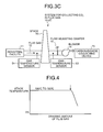
- Fig. 3C depicts still another system for collecting carbon dioxide in flue gas 10-2C according to the second embodiment.
- the gas temperature sensor S3 is arranged before the blower 14 and at the downstream side of the stack 13, and a gas temperature sensor S4 also is arranged within a stack flue at the upstream side of the stack 13.
- the drawing amount of the flue gas 12 by the blower 14 to the carbon-dioxide collecting device 15 is increased until a difference in the flue gas temperature is generated, and when the difference in the gas temperatures is generated, drawing in any more than that amount is stopped and the carbon dioxide in flue gas is collected while drawing in the flue gas by a substantially constant amount.
- Fig. 5A is a schematic diagram of the system for collecting carbon dioxide in flue gas according to the third embodiment.
- a system for collecting carbon dioxide in flue gas 10-3A includes the stack 13 that discharges the flue gas 12 discharged from the industrial facility 11 to the outside, the blower 14 that is installed at the downstream side of the stack 13 and draws the flue gas 12 therein, the carbon-dioxide collecting device 15 that collects carbon dioxide in the flue gas 12 drawn in by the blower 14, and an O 2 sensor S5 arranged within the stack 13.
- the drawing amount of the flue gas 12 by the blower 14 to the carbon-dioxide collecting device 15 is increased until the oxygen gas concentration is raised, and when the oxygen gas concentration is raised, drawing in any more than that amount is stopped and the carbon dioxide in the flue gas 12 is collected while the flue gas 12 is drawn in by a substantially constant amount.
- the O 2 sensor S5 monitors all the time the oxygen concentration of the flue gas to be discharged from the stack 13 to the outside.
- an O 2 sensor S6 is installed at the upstream side of the blower 14 at the downstream side of the stack 13, and the oxygen concentration can be measured by the O 2 sensor S6 instead of the O 2 sensor S5.
- the O 2 sensor S5 can be used together so that the oxygen concentration can be measured by the both sensors S5 and S6.
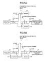
- Fig. 5B depicts another system for collecting carbon dioxide in flue gas 10-3B according to the third embodiment.
- An O 2 sensor S6 is arranged at the downstream side of the stack 13 and before the blower 14, and an O 2 sensor S7 is also arranged within the stack flue at the upstream side of the stack 13.
- the drawing amount of the flue gas 12 by the blower 14 to the carbon-dioxide collecting device 15 is increased until a difference in the oxygen concentration in the flue gas is generated, and when the difference in the oxygen concentration is generated, drawing in any more than that amount is stopped and carbon dioxide in the flue gas is collected while drawing in the flue gas by a substantially constant amount.
- Fig. 7A is a schematic diagram of the system for collecting carbon dioxide in flue gas according to the fourth embodiment.
- a system for collecting carbon dioxide in flue gas 10-4A includes the stack 13 that discharges the flue gas 12 discharged from the industrial facility 11 to the outside, the blower 14 that is installed at the downstream side of the stack 13 and draws the flue gas 12 therein, the carbon-dioxide collecting device 15 that collects carbon dioxide in the flue gas 12 drawn in by the blower 14, and a CO 2 sensor S8 arranged within the stack 13.
- the drawing amount of the flue gas 12 drawn in by the blower 14 to the carbon-dioxide collecting device 15 is increased until the carbon dioxide gas concentration decreases, and when the carbon dioxide gas concentration decreases, drawing in any more than that amount is stopped, and the carbon dioxide in the flue gas is collected while the flue gas is drawn in by a substantially constant amount.
- the CO 2 sensor S8 monitors all the time the carbon dioxide concentration of the flue gas to be discharged from the stack 13 to the outside.
- a CO 2 sensor S9 is installed at the upstream side of the blower 14 at the downstream side of the stack 13, and the carbon dioxide concentration can be measured by the CO 2 sensor S9 instead of the CO 2 sensor S8.
- the CO 2 sensor S8 can be used together so that the oxygen concentration can be measured by both the sensors S8 and S9.
- Fig. 7B depicts another system for collecting carbon dioxide in flue gas 10-4B according to the fourth embodiment.
- the CO 2 sensor S9 is arranged at the downstream side of the stack 13 and before the blower 14, and a CO 2 sensor S10 is also arranged in the stack flue at the upstream of the stack 13.
- the drawing amount of the flue gas 12 by the blower 14 to the carbon-dioxide collecting device 15 is increased until a difference in the carbon dioxide concentration in the flue gas is generated, and when the difference in the carbon dioxide concentration is generated, drawing in any more than that amount is stopped, and the carbon dioxide in flue gas is collected while drawing in the flue gas by a substantially constant amount.
- the first to fourth embodiments can be appropriately combined to use a plurality of different sensors and to perform the control.
- substantially all of a large amount of flue gas can be drawn into a carbon-dioxide collecting device with a simple facility and in a stable and safe manner.
Landscapes
- Engineering & Computer Science (AREA)
- Chemical & Material Sciences (AREA)
- Chemical Kinetics & Catalysis (AREA)
- Mechanical Engineering (AREA)
- General Engineering & Computer Science (AREA)
- Health & Medical Sciences (AREA)
- General Chemical & Material Sciences (AREA)
- Oil, Petroleum & Natural Gas (AREA)
- Analytical Chemistry (AREA)
- Combustion & Propulsion (AREA)
- Biomedical Technology (AREA)
- Environmental & Geological Engineering (AREA)
- Toxicology (AREA)
- Treating Waste Gases (AREA)
- Carbon And Carbon Compounds (AREA)
Abstract
Description
- The present invention relates to a system for collecting carbon dioxide in flue gas, capable of stably processing all the carbon dioxide in the flue gas discharged from an industrial facility such as a gas turbine, a furnace, or a boiler.
- Conventionally, to collect carbon dioxide in flue gas, for example, a system is adopted when an amine-based absorbing solvent is used as a CO2 absorbing solvent to remove and collect CO2 from flue gas; firstly, a process is performed to bring the CO2 absorbing solvent into contact with the flue gas in an absorption column, and thereafter the CO2 absorbing solvent that has absorbed CO2 is heated in a regeneration column; secondly, CO2 is freed and the CO2 absorbing solvent is regenerated, and circulated in the absorption column again, and finally, reused (for example, see Japanese Patent Application Laid-open No.
H3-193116 -
Fig. 9 is an example of a conventional system for collecting Co2 in flue gas. As shown inFig. 9 , a conventional CO2 collecting system 1000 includes an fluegas cooling device 1004 that coolsflue gas 1002 containing CO2 discharged from anindustrial facility 1001 such as a boiler and a gas turbine by coolingwater 1003, a CO2 absorption column 1006 that brings theflue gas 1002 containing cooled CO2 into contact with a CO2 absorbing solvent 1005 absorbing CO2 to remove the CO2 from theflue gas 1002, and a regeneration column 1008 that releases the CO2 from a CO2 absorbing solvent (rich solvent) 1007 absorbing the CO2 to regenerate the CO2 absorbing solvent. In this device, a regenerated CO2 absorbing solvent (lean solvent) 1009 from which the CO2 is removed in the regeneration column 1008 is recycled as the CO2 absorbing solvent in the CO2 absorption column 1006. The CO2 absorption column 1006 and the regeneration column 1008 configure a CO2 collecting device 1030. - In a CO2 collection method using the conventional CO2 collecting device 1030, the
flue gas 1002 containing CO2, discharged from the industrial facility such as a boiler and a gas turbine, is firstly sent to the fluegas cooling device 1004 after pressure is raised by aflue gas fan 1010, cooled by coolingwater 1003, and thereafter sent to the CO2 absorption column 1006. - In the CO2 absorption column 1006, the
flue gas 1002 is countercurrently contacted with, for example, the CO2 absorbing solvent 1005 based on an amine-based absorbent, and the CO2 in theflue gas 1002 is absorbed in the CO2 absorbing solvent 1005 due to a chemical reaction (R-NH2+H2O+CO2 → R-NH3HCO3), andflue gas 1011 from which the CO2 is removed is released from the system. The CO2 absorbing solvent 1007 absorbing the CO2 is also called a rich solvent. Pressure is raised for therich solvent 1007 by arich solvent pump 1012, and heated by a rich/leansolvent heat exchanger 1013 by the CO2 absorbing solvent (lean solvent) 1009 regenerated by removing CO2 in the regeneration column 1008 described later, and supplied to the regeneration column 1008. - The
rich solvent 1007 released from the upper part of the regeneration column 1008 to the interior of the regeneration column 1008 receives heat from water vapor generated inside the regeneration column 1008 and a large amount of CO2 is discharged. The CO2 absorbing solvent from which a portion or a large amount of CO2 is released inside the regeneration column 1008 is called a semi-lean solvent. The semi-lean solvent becomes a CO2 absorbing solvent from which almost all of the CO2 is removed by the time it reaches the lower portion of the regeneration column 1008. The absorbing solvent regenerated by removing almost all of the CO2 is called a lean solvent. Areboiler 1014 heats the lean solvent by using steam. Meanwhile, CO2 gas 1015 together with water vapor released from the rich solvent and the semi-lean solvent inside the regeneration column 1008 is derived from the head top part of the regeneration column 1008, the water vapor is condensed by anoverhead condenser 1016, water is separated by aseparation drum 1017, and CO2 gas 1018 is released from the system and collected. The water separated by theseparation drum 1017 is supplied by a condensed-water circulating pump 1019 to the upper part of regeneration column 1008. The regenerated CO2 absorbing solvent (lean solvent) 1009 is cooled by therich solvent 1007 by the rich/leansolvent heat exchanger 1013, which is followed by raising the pressure by alean solvent pump 1020, and the resultant water is cooled by alean solvent cooler 1021, and thereafter supplied to the CO2 absorption column 1006. - In
Fig. 9 ,reference numeral 1001a is a stack flue of theindustrial facility 1001 such as a boiler and a gas turbine, and 1001b is a stack having a damper on the inside. There are cases where the CO2 collecting device is installed after the system is completed to collect CO2 from an existing source of the flue gas and cases where it is simultaneously attached to a new source of the flue gas. - As the conventional effective utilization of the carbon dioxide in flue gas, some of the carbon dioxide in flue gas is merely collected to produce carbon dioxide for carbonated drinks and dry ice. However, the greenhouse effect caused by carbon dioxide is recently pointed out as one cause of global warming. Measures are becoming an urgent necessity internationally to protect the global environment, and also, the source of generating the carbon dioxide affects every field of human activity, which burns fossil fuels, and demands of restricting the discharge tend are becoming even stronger. Along with this tendency, in power generation facilities such as thermal power stations that use a large amount of fossil fuels, there have been a method in which flue gas of industrial facilities such as a boiler and a gas turbine is brought into contact with a CO2 absorbing solvent, all of CO2 in the flue gas is removed and collected, and a method for storing the collected CO2 without releasing it into the atmosphere.
- As described above, in the conventional CO2 collecting
system 1000, there has been proposed that, when collecting all the carbon dioxide in flue gas, a containing unit such as a valve or damper that can be opened and closed inside thestack 1001b, as shown inFig. 9 , is installed to close and stop during the operation of the CO2 collecting device and to release when the operation of the CO2 collecting device is stopped while the source of the flue gas is kept operating. - However, at the time of stopping the operation of the CO2 collecting device, unless an operation such as containment of the valve, damper or the like, which closes the interior of the stack or releasing is surely performed, discharge of flue gas is not performed smoothly, and there are occasions that the industrial facilities (such as gas turbines) at the upstream side are adversely affected.
- Further, in a turbine facility that generates electricity of 200,000 kilowatts in which 3000 ton of carbon dioxide are processed in each day, an amount of discharged flue gas becomes enormous and a stack having, for example, a diameter of 7 to 10 meters is required. Under such circumstances, a facility of a containing unit such as a valve and a damper that contains the flue gas needs to be larger.
- Accordingly, a system capable of drawing in substantially all of a large amount of flue gas to a carbon-dioxide collecting device in a simple, stable, and safe manner has been desired.
- It is an object of the present invention to at least partially solve the problems in the conventional technology.
- According to an aspect of the present invention, a system for collecting carbon dioxide in flue gas includes: a stack that discharges flue gas discharged from an industrial facility to the outside; a blower that is installed at a downstream side of the stack and draws the flue gas therein; a carbon-dioxide collecting device that collects carbon dioxide in the flue gas drawn in by the blower; and a gas flow sensor that is arranged near an exit side within the stack and measures a gas flow rate. An amount of flue gas drawn to the carbon-dioxide collecting device by the blower is increased until a flow rate of the flue gas from the stack becomes zero in the gas flow sensor, and when the flow rate of the flue gas from the stack becomes zero, drawing in any more than the amount is stopped, and the carbon dioxide in the flue gas is collected while drawing in the flue gas by a substantially constant amount.
- According to another aspect of the present invention, a system for collecting carbon dioxide in flue gas includes: a stack that discharges flue gas discharged from an industrial facility to the outside; a blower that is installed at a downstream side of the stack and draws the flue gas therein; a carbon-dioxide collecting device that collects carbon dioxide in the flue gas drawn in by the blower; and a sensor that is arranged at least in one location in a stack flue at a downstream side of the stack or within the stack and measures gas temperature or gas type. An amount of flue gas drawn to the carbon-dioxide collecting device by the blower is increased until the gas temperature or a concentration of the gas type changes in the sensor, and when the gas temperature or the concentration of the gas type changes, drawing in any more than the amount is stopped, and the carbon dioxide in the flue gas is collected while drawing in the flue gas by a substantially constant amount.
- According to still another aspect of the present invention, a system for collecting carbon dioxide in flue gas includes: a stack that discharges flue gas discharged from an industrial facility to the outside; a blower that is installed at a downstream side of the stack and draws the flue gas therein; a carbon-dioxide collecting device that collects carbon dioxide in the flue gas drawn in by the blower; and a plurality of sensors that are arranged in an stack flue at an upstream side of the stack and at a downstream side of the stack and measure gas temperature or a concentration of gas type. An amount of flue gas drawn to the carbon-dioxide collecting device by the blower is increased until a difference in the gas temperature or the concentration of the gas type is generated, and when the difference is generated, drawing in any more than the amount is stopped, and the carbon dioxide in the flue gas is collected while drawing in the flue gas by a substantially constant amount.
- In the system for collecting carbon dioxide in flue gas, the gas type may be oxygen or carbon dioxide.
- The above and other objects, features, advantages and technical and industrial significance of this invention will be better understood by reading the following detailed description of presently preferred embodiments of the invention, when considered in connection with the accompanying drawings.
-
-
Fig. 1 is a schematic diagram of a system for collecting carbon dioxide in flue gas according to a first embodiment of the present invention; -
Fig. 2 depicts a relationship between a discharged amount of flue gas from a stack and a drawing amount of flue gas in the first embodiment; -
Fig. 3A is a schematic diagram of a system for collecting carbon dioxide in flue gas according to a second embodiment of the present invention; -
Fig. 3B is a schematic diagram of another system for collecting carbon dioxide in flue gas according to the second embodiment; -
Fig. 3C is a schematic diagram of still another system for collecting carbon dioxide in flue gas according to the second embodiment; -
Fig. 4 depicts a relationship between discharged amount of flue gas from a stack and a drawing amount of flue gas in the second embodiment; -
Fig. 5A is a schematic diagram of a system for collecting carbon dioxide in flue gas according to a third embodiment of the present invention; -
Fig. 5B is a schematic diagram of another system for collecting carbon dioxide in flue gas according to the third embodiment; -
Fig. 6 depicts a relationship between oxygen concentration from a stack and a drawing amount of flue gas in the third embodiment; -
Fig. 7A is a schematic diagram of a system for collecting carbon dioxide in flue gas according to a fourth embodiment of the present invention; -
Fig. 7B is a schematic diagram of another system for collecting carbon dioxide in flue gas according to the fourth embodiment; -
Fig. 8 depicts a relationship between carbon dioxide concentration of flue gas from a stack and a drawing amount of flue gas in the fourth embodiment; and -
Fig. 9 is a schematic diagram of a conventional system for collecting carbon dioxide in flue gas. - The present invention is explained below in detail with reference to the accompanying drawings. The present invention is not limited to the embodiments. In addition, constituent elements in the following embodiments include elements that readily occur to those skilled in the art or substantially equivalent elements.
- A system for collecting carbon dioxide in flue gas according to a first embodiment of the present invention is explained with reference to the drawings.
-
Fig. 1 is a schematic diagram of the system for collecting carbon dioxide in flue gas according to the first embodiment. - As shown in
Fig. 1 , a system for collecting carbon dioxide in flue gas 10-1 according to the first embodiment includes astack 13 that dischargesflue gas 12 discharged from anindustrial facility 11 to the outside, ablower 14 that is installed at the downstream side of thestack 13 and draws theflue gas 12 therein, a carbon-dioxide collecting device 15 that collects carbon dioxide in theflue gas 12 drawn in by theblower 14, and a gas flow sensor S1 arranged near an exit side within thestack 13. In the gas flow sensor S1, a drawing amount of theflue gas 12 by theblower 14 to the carbon-dioxide collecting device 15 is increased until an exhaust flow rate of the flue gas from thestack 13 becomes zero, and when the discharged amount of flue gas from thestack 13 becomes zero, drawing in any more than that amount is stopped and the carbon dioxide in the flue gas is collected while theflue gas 12 is drawn in by a substantially constant amount. - The carbon-
dioxide collecting device 15 is not particularly limited and can be any device that collects carbon dioxide, similar to the CO2 collecting device shown in theFig. 9 . - In the first embodiment, the exhaust flow rate to the outside of the
flue gas 12 from thestack 13 is monitored all the time in the gas flow sensor S1. - When the drawing amount of
flue gas 12 by theblower 14 to the carbon-dioxide collecting device 15 is increased until the exhaust flow rate from thestack 13 becomes zero, the discharged amount of theflue gas 12 to the outside from the stack declines slowly as shown inFig. 2 . When the discharged amount of flue gas from thestack 13 becomes zero, drawing in any more than that amount by theblower 14 is stopped, and the carbon dioxide in theflue gas 12 is collected by the carbon-dioxide collecting device 15 while drawing in theflue gas 12 by theblower 14 while maintaining the drawing amount to become approximately zero (substantially constant amount). - Accordingly, all of the flue gas from the
industrial facility 11 can be stably drawn into the carbon-dioxide collecting device 15 and all of the carbon dioxide in flue gas can be collected. - Further, in the carbon-
dioxide collecting device 15, since air is mixed in the flue gas which is a target to be processed, malfunctions is not generated even when outside atmosphere is drawn into the carbon-dioxide collecting device 15 from thestack 13. - In the present invention, the industrial facility is not particularly limited, and examples thereof can include a boiler, a combustion furnace, and a gas turbine facility, which generate carbon dioxide. When the gas turbine facility is used, a heat recovery steam generator (HRSG) that collects heat having high temperature (about 580°C) of the
flue gas 12 discharged from a gas turbine can be installed. - A system for collecting carbon dioxide in flue gas according to a second embodiment of the present invention is explained next with reference to the drawings.
-
Fig. 3A is a schematic diagram of the system for collecting carbon dioxide in flue gas according to the second embodiment. - As shown in
Fig. 3A , a system for collecting carbon dioxide in flue gas 10-2A according to the second embodiment includes thestack 13 that discharges theflue gas 12 discharged from theindustrial facility 11 to the outside, theblower 14 that is installed at the downstream side of thestack 13 and draws theflue gas 12 therein, the carbon-dioxide collecting device 15 that collects carbon dioxide in theflue gas 12 drawn in by theblower 14, and a gas temperature sensor S2 arranged within thestack 13. In the gas temperature sensor S2, the drawing amount of theflue gas 12 by theblower 14 to the carbon-dioxide collecting device 15 is increased until the gas temperature declines, and when the gas temperature declines, drawing in any more than that amount is stopped and the carbon dioxide in the flue gas is collected while theflue gas 12 is drawn in by a substantially constant amount. - That is, in the gas temperature sensor S2, the exhaust temperature of the flue gas to be discharged from the
stack 13 to the outside is monitored all the time by the gas temperature sensor S2. - Even when the drawing amount of the
flue gas 12 by theblower 14 to the carbon-dioxide collecting device 15 is increased, the exhaust temperature from thestack 13 is almost maintained at constant temperature (100 to 180°C) up to a certain time point as shown inFig. 4 . However, when atmosphere from outside thestack 13 flows in within thestack 13, theflue gas 12 is cooled by the atmosphere, and the temperature declines. Additionally, immediately before the temperature change starts (a point indicated by an arrow inFig. 4 ), drawing in theflue gas 12 by theblower 14 any more than that amount is stopped, and the carbon dioxide in theflue gas 12 is collected by the carbon-dioxide collecting device 15 while drawing in theflue gas 12 by theblower 14 while maintaining the stopped drawing amount (substantially constant amount). - Accordingly, all of the flue gas from the
industrial facility 11 can be stably drawn into the carbon-dioxide collecting device 15 and all of the carbon dioxide in flue gas can be collected. -
Fig. 3B depicts another system for collecting carbon dioxide in flue gas 10-2B according to the second embodiment. A gas temperature sensor S3 is arranged before theblower 14 at the downstream side of the stack, and similarly, the gas temperature is measured and the flue gas is drawn in. - By using the gas temperature sensor S3 to control the drawing amount while monitoring the gas temperature in the same way as the gas temperature sensor S2, all of the flue gas from the
industrial facility 11 can be stably drawn into the carbon-dioxide collecting device 15 and all of the carbon dioxide in the flue gas can be collected. -
Fig. 3C depicts still another system for collecting carbon dioxide in flue gas 10-2C according to the second embodiment. The gas temperature sensor S3 is arranged before theblower 14 and at the downstream side of thestack 13, and a gas temperature sensor S4 also is arranged within a stack flue at the upstream side of thestack 13. - In the gas temperature sensors S3 and S4, the drawing amount of the
flue gas 12 by theblower 14 to the carbon-dioxide collecting device 15 is increased until a difference in the flue gas temperature is generated, and when the difference in the gas temperatures is generated, drawing in any more than that amount is stopped and the carbon dioxide in flue gas is collected while drawing in the flue gas by a substantially constant amount. - Accordingly, all of the flue gas from the
industrial facility 11 can be stably drawn into the carbon-dioxide collecting device 15. - A system for collecting carbon dioxide in flue gas according to a third embodiment of the present invention is explained next with reference to the drawings.
-
Fig. 5A is a schematic diagram of the system for collecting carbon dioxide in flue gas according to the third embodiment. - As shown in
Fig. 5A , a system for collecting carbon dioxide in flue gas 10-3A according to the third embodiment includes thestack 13 that discharges theflue gas 12 discharged from theindustrial facility 11 to the outside, theblower 14 that is installed at the downstream side of thestack 13 and draws theflue gas 12 therein, the carbon-dioxide collecting device 15 that collects carbon dioxide in theflue gas 12 drawn in by theblower 14, and an O2 sensor S5 arranged within thestack 13. In the O2 sensor S5, the drawing amount of theflue gas 12 by theblower 14 to the carbon-dioxide collecting device 15 is increased until the oxygen gas concentration is raised, and when the oxygen gas concentration is raised, drawing in any more than that amount is stopped and the carbon dioxide in theflue gas 12 is collected while theflue gas 12 is drawn in by a substantially constant amount. - That is, in the O2 sensor S5, the O2 sensor S5 monitors all the time the oxygen concentration of the flue gas to be discharged from the
stack 13 to the outside. - Even when the drawing amount of the
flue gas 12 by theblower 14 to the carbon-dioxide collecting device 15 is increased, the oxygen concentration of flue gas from the stack is maintained almost at constant (in a case of the flue gas from a boiler, it is 2 to 5%, and in a case of the flue gas from a gas turbine, it is 12 to 15%) up to a certain time point as shown inFig. 6 . However, when atmosphere from outside of thestack 13 flows into the stack, oxygen in the atmosphere is mixed in theflue gas 12, and the oxygen concentration is raised. Immediately before the concentration change in oxygen starts (a point indicated by an arrow inFig. 6 ), drawing in anymore flue gas 12 by theblower 14 is stopped, and carbon dioxide in theflue gas 12 is collected by the carbon-dioxide collecting device 15 while drawing in theflue gas 12 by theblower 14, maintaining the stopped drawing amount (substantially constant amount) at the same time. - Accordingly, all of the flue gas from the
industrial facility 11 can be stably drawn into the carbon-dioxide collecting device 15 and all of the carbon dioxide in flue gas can be collected. - In
Fig. 5A , an O2 sensor S6 is installed at the upstream side of theblower 14 at the downstream side of thestack 13, and the oxygen concentration can be measured by the O2 sensor S6 instead of the O2 sensor S5. At this time, the O2 sensor S5 can be used together so that the oxygen concentration can be measured by the both sensors S5 and S6. -
Fig. 5B depicts another system for collecting carbon dioxide in flue gas 10-3B according to the third embodiment. An O2 sensor S6 is arranged at the downstream side of thestack 13 and before theblower 14, and an O2 sensor S7 is also arranged within the stack flue at the upstream side of thestack 13. - In the O2 sensors S6 and S7, the drawing amount of the
flue gas 12 by theblower 14 to the carbon-dioxide collecting device 15 is increased until a difference in the oxygen concentration in the flue gas is generated, and when the difference in the oxygen concentration is generated, drawing in any more than that amount is stopped and carbon dioxide in the flue gas is collected while drawing in the flue gas by a substantially constant amount. - Accordingly, all of the flue gas from the
industrial facility 11 can be stably drawn into the carbon-dioxide collecting device 15. - A system for collecting carbon dioxide in flue gas according to a fourth embodiment of the present invention is explained next with reference to the drawings.
-
Fig. 7A is a schematic diagram of the system for collecting carbon dioxide in flue gas according to the fourth embodiment. - As shown in
Fig. 7A , a system for collecting carbon dioxide in flue gas 10-4A according to the fourth embodiment includes thestack 13 that discharges theflue gas 12 discharged from theindustrial facility 11 to the outside, theblower 14 that is installed at the downstream side of thestack 13 and draws theflue gas 12 therein, the carbon-dioxide collecting device 15 that collects carbon dioxide in theflue gas 12 drawn in by theblower 14, and a CO2 sensor S8 arranged within thestack 13. In the CO2 sensor S8, the drawing amount of theflue gas 12 drawn in by theblower 14 to the carbon-dioxide collecting device 15 is increased until the carbon dioxide gas concentration decreases, and when the carbon dioxide gas concentration decreases, drawing in any more than that amount is stopped, and the carbon dioxide in the flue gas is collected while the flue gas is drawn in by a substantially constant amount. - That is, in the CO2 sensor S8, the CO2 sensor S8 monitors all the time the carbon dioxide concentration of the flue gas to be discharged from the
stack 13 to the outside. - Even when the drawing amount of the
flue gas 12 by theblower 14 to the carbon-dioxide collecting device 15 is increased, the carbon dioxide concentration of flue gas from the stack is maintained almost at constant (in a case of the flue gas from a boiler, it is 8 to 14% and in a case of the flue gas from a gas turbine, it is 3.5 to 4%) up to a certain time point as shown inFig. 8 . However, when atmosphere flows in the stack from outside of thestack 13, carbon dioxide in the atmosphere is mixed in theflue gas 12, and the carbon dioxide concentration decreases. Immediately before the concentration change of the carbon dioxide starts (a point indicated by an arrow inFig. 8 ), drawing in anymore flue gas 12 by theblower 14 is stopped, and the carbon dioxide in theflue gas 12 is collected by the carbon-dioxide collecting device 15 while drawing in theflue gas 12 by theblower 14 while maintaining the stopped drawing amount (substantially constant amount). - Accordingly, all of the flue gas from the
industrial facility 11 can be stably drawn into the carbon-dioxide collecting device 15 and all of the carbon dioxide in flue gas can be collected. - In
Fig. 7A , a CO2 sensor S9 is installed at the upstream side of theblower 14 at the downstream side of thestack 13, and the carbon dioxide concentration can be measured by the CO2 sensor S9 instead of the CO2 sensor S8. At this time, the CO2 sensor S8 can be used together so that the oxygen concentration can be measured by both the sensors S8 and S9. -
Fig. 7B depicts another system for collecting carbon dioxide in flue gas 10-4B according to the fourth embodiment. The CO2 sensor S9 is arranged at the downstream side of thestack 13 and before theblower 14, and a CO2 sensor S10 is also arranged in the stack flue at the upstream of thestack 13. - In the CO2 sensors S9 and S10, the drawing amount of the
flue gas 12 by theblower 14 to the carbon-dioxide collecting device 15 is increased until a difference in the carbon dioxide concentration in the flue gas is generated, and when the difference in the carbon dioxide concentration is generated, drawing in any more than that amount is stopped, and the carbon dioxide in flue gas is collected while drawing in the flue gas by a substantially constant amount. - Accordingly, all of the flue gas from the
industrial facility 11 can be stably drawn into the carbon-dioxide collecting device 15. - To achieve more accurate control, the first to fourth embodiments can be appropriately combined to use a plurality of different sensors and to perform the control.
- According to the present invention, substantially all of a large amount of flue gas can be drawn into a carbon-dioxide collecting device with a simple facility and in a stable and safe manner.
- Although the invention has been described with respect to specific embodiments for a complete and clear disclosure, the appended claims are not to be thus limited but are to be construed as embodying all modifications and alternative constructions that may occur to one skilled in the art that fairly fall within the basic teaching herein set forth.
Claims (4)
- A system for collecting carbon dioxide in flue gas, characterized in that it comprises:a stack (13) that discharges flue gas (12) discharged from an industrial facility (11) to the outside;a blower (14) that is installed at a downstream side of the stack (13) and draws the flue gas (12) therein;a carbon-dioxide collecting device (15) that collects carbon dioxide in the flue gas (12) drawn in by the blower (14); anda gas flow sensor (S1) that is arranged near an exit side within the stack (13) and measures a gas flow rate, whereinan amount of flue gas (12) drawn to the carbon-dioxide collecting device (15) by the blower (14) is increased until a flow rate of the flue gas from the stack (13) becomes zero in the gas flow sensor, andwhen the flow rate of the flue gas from the stack (13) becomes zero, drawing in any more than the amount is stopped, and the carbon dioxide in the flue gas is collected while drawing in the flue gas by a substantially constant amount.
- A system for collecting carbon dioxide in flue gas, characterized in that it comprises:a stack (13) that discharges flue gas (12) discharged from an industrial facility (11) to the outside;a blower (14) that is installed at a downstream side of the stack (13) and draws the flue gas (12) therein;a carbon-dioxide collecting device (15) that collects carbon dioxide in the flue gas (12) drawn in by the blower (14); anda sensor (S2) that is arranged at least in one location in a stack flue at a downstream side of the stack (13) or within the stack (13) and measures gas temperature or gas type, whereinan amount of flue gas (12) drawn to the carbon-dioxide collecting device (15) by the blower (14) is increased until the gas temperature or a concentration of the gas type changes in the sensor, andwhen the gas temperature or the concentration of the gas type changes, drawing in any more than the amount is stopped, and the carbon dioxide in the flue gas is collected while drawing in the flue gas by a substantially constant amount.
- A system for collecting carbon dioxide in flue gas, characterized in that it comprises:a stack (13) that discharges flue gas (12) discharged from an industrial facility (11) to the outside;a blower (14) that is installed at a downstream side of the stack (13) and draws the flue gas (12) therein;a carbon-dioxide collecting device (15) that collects carbon dioxide in the flue gas (12) drawn in by the blower (14); anda plurality of sensors (S2) that are arranged in an stack flue at an upstream side of the stack (13) and at a downstream side of the stack (13) and measure gas temperature or a concentration of gas type, whereinan amount of flue gas (12) drawn to the carbon-dioxide collecting device (15) by the blower (14) is increased until a difference in the gas temperature or the concentration of the gas type is generated, andwhen the difference is generated, drawing in any more than the amount is stopped, and the carbon dioxide in the flue gas is collected while drawing in the flue gas by a substantially constant amount.
- The system for collecting carbon dioxide in flue gas according to claim 2 or 3, wherein the gas type is oxygen or carbon dioxide.
Applications Claiming Priority (1)
| Application Number | Priority Date | Filing Date | Title |
|---|---|---|---|
| JP2008178260A JP5039651B2 (en) | 2008-07-08 | 2008-07-08 | Carbon dioxide recovery system in exhaust gas |
Publications (2)
| Publication Number | Publication Date |
|---|---|
| EP2143475A2 true EP2143475A2 (en) | 2010-01-13 |
| EP2143475A3 EP2143475A3 (en) | 2012-08-08 |
Family
ID=41165194
Family Applications (1)
| Application Number | Title | Priority Date | Filing Date |
|---|---|---|---|
| EP09152751A Withdrawn EP2143475A3 (en) | 2008-07-08 | 2009-02-13 | System for collecting carbon dioxide in flue gas |
Country Status (6)
| Country | Link |
|---|---|
| US (3) | US8623286B2 (en) |
| EP (1) | EP2143475A3 (en) |
| JP (1) | JP5039651B2 (en) |
| AU (1) | AU2009200486B2 (en) |
| CA (1) | CA2653149C (en) |
| RU (1) | RU2404842C2 (en) |
Cited By (3)
| Publication number | Priority date | Publication date | Assignee | Title |
|---|---|---|---|---|
| FR2956592A1 (en) * | 2010-02-23 | 2011-08-26 | Air Liquide | METHOD OF TREATING SMOKE FROM COMBUSTION |
| JP2023168089A (en) * | 2022-05-13 | 2023-11-24 | 三菱重工業株式会社 | Power generation facility, exhaust gas treatment system, and exhaust gas treatment method |
| EP4635604A4 (en) * | 2023-02-16 | 2026-03-11 | Mitsubishi Heavy Ind Ltd | CONTROL DEVICE, EXHAUST SYSTEM, CONTROL METHOD AND PROGRAM |
Families Citing this family (24)
| Publication number | Priority date | Publication date | Assignee | Title |
|---|---|---|---|---|
| US8192530B2 (en) | 2007-12-13 | 2012-06-05 | Alstom Technology Ltd | System and method for regeneration of an absorbent solution |
| US8435325B2 (en) * | 2008-10-23 | 2013-05-07 | Hitachi, Ltd. | Method and device for removing CO2 and H2S |
| JP5372859B2 (en) * | 2010-07-22 | 2013-12-18 | 東京瓦斯株式会社 | CO2 recovery type power generation system and operation control method thereof |
| US9133407B2 (en) | 2011-02-25 | 2015-09-15 | Alstom Technology Ltd | Systems and processes for removing volatile degradation products produced in gas purification |
| US8864878B2 (en) | 2011-09-23 | 2014-10-21 | Alstom Technology Ltd | Heat integration of a cement manufacturing plant with an absorption based carbon dioxide capture process |
| US8911538B2 (en) | 2011-12-22 | 2014-12-16 | Alstom Technology Ltd | Method and system for treating an effluent stream generated by a carbon capture system |
| JP6216490B2 (en) | 2012-02-03 | 2017-10-18 | 三菱重工業株式会社 | CO2 recovery device |
| US9028654B2 (en) | 2012-02-29 | 2015-05-12 | Alstom Technology Ltd | Method of treatment of amine waste water and a system for accomplishing the same |
| US10195561B2 (en) * | 2012-09-20 | 2019-02-05 | Mitsubishi Heavy Industries Engineering, Ltd. | Steam supply system and CO2 recovery unit including the same |
| US20140109575A1 (en) * | 2012-10-22 | 2014-04-24 | Fluor Technologies Corporation | Method for reducing flue gas carbon dioxide emissions |
| US9101912B2 (en) | 2012-11-05 | 2015-08-11 | Alstom Technology Ltd | Method for regeneration of solid amine CO2 capture beds |
| US9901870B2 (en) * | 2013-04-09 | 2018-02-27 | Kabushiki Kaisha Toshiba | Carbon dioxide capturing system and method of operating same |
| US9897313B2 (en) * | 2013-11-27 | 2018-02-20 | Jahchinedu James | Water-based system and method of collecting and transporting exhaust gas |
| KR101408834B1 (en) * | 2014-01-06 | 2014-06-20 | 한국지역난방공사 | Extracting device supplying fixed quantity of exhaust gas for industrial facility |
| JP6327941B2 (en) * | 2014-05-15 | 2018-05-23 | 三菱重工業株式会社 | Gas turbine cycle equipment, CO2 recovery equipment for exhaust gas, and exhaust heat recovery method for combustion exhaust gas |
| CN105402751B (en) * | 2015-10-30 | 2017-12-22 | 中石化宁波工程有限公司 | Gas fired-boiler and gas turbine flue gas are used for the system of air-conditioning storage and the concocting method of the system |
| CN105299671B (en) * | 2015-10-30 | 2018-06-08 | 中石化宁波工程有限公司 | Coal-fired, smoke of oil-fuel boiler is for the system of air-conditioning storage and the concocting method of the system |
| EP3267101B1 (en) * | 2016-07-06 | 2022-06-29 | Technip France | Flue gas exhaust system, industrial furnace and plant |
| JP6878912B2 (en) * | 2017-01-26 | 2021-06-02 | 三菱ケミカル株式会社 | How to make carbon dioxide |
| JP6878913B2 (en) * | 2017-01-26 | 2021-06-02 | 三菱ケミカル株式会社 | How to make carbon dioxide |
| NO347320B1 (en) * | 2021-11-23 | 2023-09-18 | Aker Carbon Capture Norway As | Plant and Method of Controlling an Industrial Plant having a Flue Gas Processing System |
| FR3130637B1 (en) * | 2021-12-21 | 2024-11-01 | Air Liquide | Process for treating smoke containing carbon dioxide |
| NO349006B1 (en) * | 2024-04-19 | 2025-08-25 | Lunna Eiendom As | Device and method for CO2 up-concentration |
| JP2025183762A (en) * | 2024-06-05 | 2025-12-17 | 三菱重工業株式会社 | Control device, exhaust gas supply system, and control method |
Citations (1)
| Publication number | Priority date | Publication date | Assignee | Title |
|---|---|---|---|---|
| JPH03193116A (en) | 1989-12-25 | 1991-08-22 | Mitsubishi Heavy Ind Ltd | Removal of co2 combustion exhaust gas |
Family Cites Families (29)
| Publication number | Priority date | Publication date | Assignee | Title |
|---|---|---|---|---|
| US3395512A (en) * | 1966-03-21 | 1968-08-06 | Universal Oil Prod Co | Method and means for cooling and cleaning hot converter gases |
| DE2239578C3 (en) | 1971-12-20 | 1982-07-22 | Verfahrenstechnik Dr.-Ing. Kurt Baum, 4300 Essen | Gas collecting hood for converter |
| US3908969A (en) * | 1971-12-20 | 1975-09-30 | Pennsylvania Engineering Corp | Method and apparatus for air pollution control combined with safe recovery and control of gases from a bottom-blown steel converter vessel |
| US4113005A (en) * | 1977-04-22 | 1978-09-12 | John Zink Company | Waste heat boiler temperature control system |
| US4273312A (en) * | 1979-03-22 | 1981-06-16 | Dravo Corporation | Method of process off-gas control |
| US4245569A (en) * | 1979-03-26 | 1981-01-20 | Combustion Engineering, Inc. | Scrubber bypass system |
| US4234170A (en) * | 1979-06-06 | 1980-11-18 | National Steel Corporation | Movable charging emissions control hood for BOF |
| US4487139A (en) * | 1979-10-04 | 1984-12-11 | Heat Exchanger Industries, Inc. | Exhaust gas treatment method and apparatus |
| JPS57164910A (en) | 1981-04-01 | 1982-10-09 | Sumitomo Metal Ind Ltd | Method for rocovering waste gas of converter |
| DE3114954A1 (en) * | 1981-04-13 | 1982-11-04 | Honeywell B.V., Amsterdam | CONTROL DEVICE FOR A GAS-FIRED WATER OR AIR HEATER |
| GB2100471B (en) * | 1981-05-28 | 1985-03-06 | British Gas Corp | Automatic coi removal system and operation thereof |
| JPS6119718A (en) * | 1984-07-06 | 1986-01-28 | Nippon Steel Corp | Operating method of exhaust gas disposing system of closed-type converter in abnormal time |
| JPS6241514A (en) * | 1985-08-14 | 1987-02-23 | Ishikawajima Harima Heavy Ind Co Ltd | Ventilation control method for flue gas in flue gas desulfurization equipment |
| JPS6374938U (en) * | 1986-10-31 | 1988-05-18 | ||
| WO1990009225A2 (en) | 1989-02-15 | 1990-08-23 | George Miklos Kota | Apparatus and process for the elimination of atmospheric pollution |
| JPH04200719A (en) * | 1990-11-30 | 1992-07-21 | Sumitomo Chem Co Ltd | Carbon oxide removal device |
| US5347958A (en) * | 1992-12-31 | 1994-09-20 | Gordon Jr Merrill K | Heat recovery apparatus and an improved heat recovery method |
| US5606495A (en) * | 1994-03-03 | 1997-02-25 | Jaidka; Sandeep | Device for controlling air pollution |
| JP3486220B2 (en) | 1994-03-08 | 2004-01-13 | バブコック日立株式会社 | Combustion exhaust gas purification method and apparatus |
| US5505766A (en) * | 1994-07-12 | 1996-04-09 | Electric Power Research, Inc. | Method for removing pollutants from a combustor flue gas and system for same |
| US5609522A (en) * | 1995-01-18 | 1997-03-11 | Szwartz; Henry S. | Combination damper and chimney cap apparatus |
| JPH10165752A (en) * | 1996-12-16 | 1998-06-23 | Nippon Steel Corp | Exhaust gas treatment method in waste treatment equipment |
| WO2002020136A1 (en) * | 2000-09-06 | 2002-03-14 | Colorado Altitude Training Llc | Altitude simulation method and system |
| CN1938547A (en) | 2004-04-09 | 2007-03-28 | 村松风送设备工业株式会社 | Remote monitoring system of combustion exhaust gas treatment plant |
| JP4821102B2 (en) * | 2004-09-10 | 2011-11-24 | Jfeエンジニアリング株式会社 | Desalination control device and desalination control method |
| JP4745682B2 (en) * | 2005-02-23 | 2011-08-10 | 関西電力株式会社 | CO2 recovery apparatus and method |
| US7442035B2 (en) * | 2005-04-26 | 2008-10-28 | Gei Development, Llc | Gas induction bustle for use with a flare or exhaust stack |
| JP4773865B2 (en) * | 2006-04-13 | 2011-09-14 | 三菱重工業株式会社 | CO2 recovery device and CO2 recovery method |
| US8728423B2 (en) * | 2008-04-07 | 2014-05-20 | Mitsubishi Heavy Industries, Ltd. | Method and apparatus for flue gas treatment |
-
2008
- 2008-07-08 JP JP2008178260A patent/JP5039651B2/en not_active Expired - Fee Related
-
2009
- 2009-02-09 CA CA2653149A patent/CA2653149C/en not_active Expired - Fee Related
- 2009-02-09 AU AU2009200486A patent/AU2009200486B2/en not_active Ceased
- 2009-02-10 US US12/368,474 patent/US8623286B2/en not_active Expired - Fee Related
- 2009-02-12 RU RU2009104915/05A patent/RU2404842C2/en not_active IP Right Cessation
- 2009-02-13 EP EP09152751A patent/EP2143475A3/en not_active Withdrawn
-
2013
- 2013-12-02 US US14/094,180 patent/US9249711B2/en not_active Expired - Fee Related
- 2013-12-02 US US14/094,197 patent/US9341101B2/en not_active Expired - Fee Related
Patent Citations (1)
| Publication number | Priority date | Publication date | Assignee | Title |
|---|---|---|---|---|
| JPH03193116A (en) | 1989-12-25 | 1991-08-22 | Mitsubishi Heavy Ind Ltd | Removal of co2 combustion exhaust gas |
Cited By (5)
| Publication number | Priority date | Publication date | Assignee | Title |
|---|---|---|---|---|
| FR2956592A1 (en) * | 2010-02-23 | 2011-08-26 | Air Liquide | METHOD OF TREATING SMOKE FROM COMBUSTION |
| WO2011104464A1 (en) * | 2010-02-23 | 2011-09-01 | L'air Liquide, Societe Anonyme Pour L'etude Et L'exploitation Des Procedes Georges Claude | Method for treating combustion fumes |
| JP2023168089A (en) * | 2022-05-13 | 2023-11-24 | 三菱重工業株式会社 | Power generation facility, exhaust gas treatment system, and exhaust gas treatment method |
| EP4509759A4 (en) * | 2022-05-13 | 2025-10-29 | Mitsubishi Heavy Ind Ltd | POWER GENERATION PLANT, EXHAUST ENGINEERING SYSTEM AND EXHAUST ENGINEERING PROCESS |
| EP4635604A4 (en) * | 2023-02-16 | 2026-03-11 | Mitsubishi Heavy Ind Ltd | CONTROL DEVICE, EXHAUST SYSTEM, CONTROL METHOD AND PROGRAM |
Also Published As
| Publication number | Publication date |
|---|---|
| JP5039651B2 (en) | 2012-10-03 |
| AU2009200486A1 (en) | 2010-01-28 |
| US20140086798A1 (en) | 2014-03-27 |
| JP2010017617A (en) | 2010-01-28 |
| RU2404842C2 (en) | 2010-11-27 |
| CA2653149C (en) | 2011-04-05 |
| US9249711B2 (en) | 2016-02-02 |
| CA2653149A1 (en) | 2010-01-08 |
| US9341101B2 (en) | 2016-05-17 |
| US8623286B2 (en) | 2014-01-07 |
| RU2009104915A (en) | 2010-08-20 |
| AU2009200486B2 (en) | 2010-12-23 |
| US20140086799A1 (en) | 2014-03-27 |
| EP2143475A3 (en) | 2012-08-08 |
| US20100005722A1 (en) | 2010-01-14 |
Similar Documents
| Publication | Publication Date | Title |
|---|---|---|
| CA2653149C (en) | System for collecting carbon dioxide in flue gas | |
| JP6072055B2 (en) | Exhaust gas treatment system and method | |
| JP5383339B2 (en) | Concentration management method for CO2 absorbent used in CO2 recovery equipment | |
| EP2722097A1 (en) | Combustion exhaust gas treatment system and combustion exhaust gas treatment method | |
| CA2877852C (en) | Exhaust gas treatment system | |
| JP2015166090A (en) | Exhaust gas treatment system and exhaust gas treatment method | |
| JP5931834B2 (en) | Reclaiming apparatus and method, CO2 and / or H2S recovery apparatus | |
| JP2014124590A (en) | Operation method of boiler system | |
| JP2011194292A (en) | Method and apparatus for treating exhaust gas | |
| JP6173734B2 (en) | Exhaust gas treatment system | |
| JP2010100491A (en) | Device and method for carbon dioxide recovery | |
| JP4773865B2 (en) | CO2 recovery device and CO2 recovery method | |
| JP6225574B2 (en) | Carbon dioxide recovery method and recovery apparatus | |
| US20140199218A1 (en) | Method and apparatus for zero emission combined heat and power | |
| KR101377635B1 (en) | Carbon dioxide collecting apparatus | |
| WO2022263799A1 (en) | Methods and systems for the removal of impurities in a flue gas |
Legal Events
| Date | Code | Title | Description |
|---|---|---|---|
| PUAI | Public reference made under article 153(3) epc to a published international application that has entered the european phase |
Free format text: ORIGINAL CODE: 0009012 |
|
| AK | Designated contracting states |
Kind code of ref document: A2 Designated state(s): AT BE BG CH CY CZ DE DK EE ES FI FR GB GR HR HU IE IS IT LI LT LU LV MC MK MT NL NO PL PT RO SE SI SK TR |
|
| AX | Request for extension of the european patent |
Extension state: AL BA RS |
|
| RIC1 | Information provided on ipc code assigned before grant |
Ipc: B01D 53/34 20060101ALI20120227BHEP Ipc: F23J 15/02 20060101ALI20120227BHEP Ipc: B01D 53/62 20060101ALI20120227BHEP Ipc: B01D 53/14 20060101AFI20120227BHEP |
|
| PUAL | Search report despatched |
Free format text: ORIGINAL CODE: 0009013 |
|
| AK | Designated contracting states |
Kind code of ref document: A3 Designated state(s): AT BE BG CH CY CZ DE DK EE ES FI FR GB GR HR HU IE IS IT LI LT LU LV MC MK MT NL NO PL PT RO SE SI SK TR |
|
| AX | Request for extension of the european patent |
Extension state: AL BA RS |
|
| RIC1 | Information provided on ipc code assigned before grant |
Ipc: B01D 53/14 20060101AFI20120702BHEP Ipc: B01D 53/34 20060101ALI20120702BHEP Ipc: B01D 53/62 20060101ALI20120702BHEP Ipc: F23J 15/02 20060101ALI20120702BHEP |
|
| 17P | Request for examination filed |
Effective date: 20130124 |
|
| AKX | Designation fees paid |
Designated state(s): DE FR GB IT NL NO |
|
| 17Q | First examination report despatched |
Effective date: 20170616 |
|
| STAA | Information on the status of an ep patent application or granted ep patent |
Free format text: STATUS: THE APPLICATION IS DEEMED TO BE WITHDRAWN |
|
| 18D | Application deemed to be withdrawn |
Effective date: 20180901 |