EP2143317A1 - Guides for an extendable harvesting header - Google Patents
Guides for an extendable harvesting header Download PDFInfo
- Publication number
- EP2143317A1 EP2143317A1 EP08159966A EP08159966A EP2143317A1 EP 2143317 A1 EP2143317 A1 EP 2143317A1 EP 08159966 A EP08159966 A EP 08159966A EP 08159966 A EP08159966 A EP 08159966A EP 2143317 A1 EP2143317 A1 EP 2143317A1
- Authority
- EP
- European Patent Office
- Prior art keywords
- header
- header according
- telescopic
- cutterbar
- guide means
- Prior art date
- Legal status (The legal status is an assumption and is not a legal conclusion. Google has not performed a legal analysis and makes no representation as to the accuracy of the status listed.)
- Granted
Links
Images



Classifications
-
- A—HUMAN NECESSITIES
- A01—AGRICULTURE; FORESTRY; ANIMAL HUSBANDRY; HUNTING; TRAPPING; FISHING
- A01D—HARVESTING; MOWING
- A01D41/00—Combines, i.e. harvesters or mowers combined with threshing devices
- A01D41/12—Details of combines
- A01D41/14—Mowing tables
- A01D41/148—Telescopic headers
Definitions
- the present invention relates to guides for the movable cutterbar table of an extendable header for a harvesting machine.
- a header for a harvesting machine typically includes a cutterbar which is operable to cut standing crop as the machine moves forward and a rotatable reel which carries tines to engage the standing crop and sweep it towards the cutterbar for cutting and then carry the cut material towards an auger before releasing it.
- the auger usually consolidates the cut crop material centrally of the header before it is passed on to an elevator and therefrom into the body of the machine for processing.
- the position of the cutterbar in relation to the auger is critical and in general depends on the type and condition of the crop to be harvested. Small grain crops usually allow a relative small distance between the cutterbar and the auger, while crops such as long-stemmed grains and canola are harvested better with the cutterbar set at a larger distance from the auger. For these reasons the cutterbar and the associated table section may be made adjustable in a generally fore-and-aft direction of the header.
- U-shaped or rectangular guides Another problem with current U-shaped or rectangular guides is the lateral movement that is caused by the side movement of the knives.
- the guides have some lateral clearance and the forces generated by the knife movement on the frame are significant, in such a way that the movable table continuously shifts sideways during cutterbar operation. This limits the lifetime of the header considerably.
- a header for a harvesting machine comprising:
- the present invention has some important advantages.
- the inclined side wall provides for a fixed position of the cutterbar table with no clearance between the member and the slide surface of the telescopic assembly. Consequently, the lateral vibrations induced by the reciprocating cutterbar will not result in lateral movement of the table to the header frame.
- the header is much more stable and works more quietly. This also reduces the wear between the telescopic members.
- a single inclined wall would suffice, but a pair of inclined walls is preferable, giving the telescopic member an overall V-shape.
- the inclined side wall or side walls may be arranged at an angle of about 45° to the horizontal, which provides a positive position for the cutterhead table, but does not clamp the members into each other.
- the guide means may comprise wear parts that can be replaced.
- the use of replaceable wear parts reduces the effects of wear on the frame and the movable table. They may include caps or strips on the front end of the telescopic assembly.
- the guides may be adjusted, e.g. by screws, so as to compensate for wear and take away the possibility for lateral displacement of the movable table. The adjustment can also be used to minimise the vertical clearance between the inner and outer telescopic members. This improves the stability of the header table during operation.
- a further advantage is that the wear guides of the present invention have no parts sticking out of the bottom of the header, hereby preserving the minimum available stubble height.
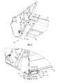
- Figures 1 to 6 illustrate an extendable header 10 comprising a main frame 12 and a movable cutterbar table 14.
- the main frame 12 is releasably attached to an elevator of a combine harvester 16 and supports a transverse auger (not shown), which can be rotated to transport crop from the cutterbar table 14 to a central outlet opening 18 adjacent the elevator.
- the cutterbar table 14 comprises a cutterbar having a range of knives (not shown), which are reciprocated by an appropriate cutterbar drive (not shown) for cutting standing crop as the combine harvester 16 is travelled over a field.
- the header frame 12 is provided with a reel 20, which extends the full width of the header and can be rotated to guide the standing crop to the cutterbar table 14 and the cut crop to the transverse auger.
- the header 10 incorporates an embodiment of an improved guidance of the movable cutterbar table 14 according to the present invention.
- the movable table 14 of the harvesting header 10 is connected to the header frame 12 by means of telescopic assemblies 22, each comprising a pair of telescopic members 24, 26.
- the outer members 24 are mounted at the bottom of the main header frame 12; the inner members 26 are mounted to the bottom of the movable cutterbar table 14 and extend rearwardly into the outer members 24.
- the telescopic members have downwardly and inwardly inclined side walls 28, 30, giving the members a cross-sectional V-shape.
- at least a two, but preferably four, five or six pairs of telescopic guide assemblies 22 are provided (two shown in Figure 2 ).
- the present invention provides for telescopic member assemblies 22 that prevent the sideways movement of the cutterbar table 14 and decrease the consequent wear by using inclined longitudinal guide surfaces.
- these inclined guide surfaces are constituted by the side walls 30 of the inner telescopic member 26. These may be arranged at a downward and inward angle of about 45° to the bottom of the cutterbar table 14.
- the side walls 30 may be connected to each other at the bottom of the member and thereby provide a triangular cross section, but in the embodiment illustrated they end at a horizontal plate 32 that closes the bottom of the inner member 26.
- the space inside the inner member 26 is used for installing a linear actuator, such as a hydraulic cylinder 40 or an electrical actuator comprising a screw and rod assembly.
- a linear actuator such as a hydraulic cylinder 40 or an electrical actuator comprising a screw and rod assembly.
- the rear end of the actuator is connected to a lug 42 at the rear of the header frame 12 and the front end to a block 44, welded to the interior of the member 26.
- the actuators of the telescopic assemblies 22 can be extended and retracted simultaneously for adjusting the forward position of the table 14 and its cutterbar as indicated by arrow A in Figure 1 .
- the outer telescopic members 24 are provided with guide means 50, which slidingly support the inner telescopic members 26 during and after their fore-and-aft movement.
- the guide means 50 comprise inclined slide surfaces 52, which are arranged against the side walls 30 of the inner member 26.
- the surfaces 52 preferably are made out of plastic material such as polyethylene or polyamide, but also other low friction material may be used.
- the guide means 50 comprise replaceable plastic caps 54 that are mounted on screws 56. These screws are set in threaded bushings 58 that are welded to the inclined side walls 28 of the outer telescopic member 24. The position of the caps 54 and hence of the inner member 26 can be adjusted by rotating the screws 56. The operator then secures them by lock nuts 60 on the outside of the side walls 28.
- the guide means 24 preferably comprises four sets of screws 56 and caps 54, all arranged near the front end of the outer telescopic member 24.
- the screws can be adjusted for compensating for wear of the slide surfaces 52.
- the operator wishing to replace the caps 54 can turn the screws 56 outwardly, remove the worn caps and insert new caps through the front space between the inner and outer telescopic members 26, 24.
- the guide means may comprise V-shaped wear blocks, which are inserted into the telescopic assembly 22 between the inner and outer members 26, 24.
- a V-shaped wear coating is provided into the guides.
- the guides are U-shaped, or any other shape, and an adapted wear block or coating is provided having an inner V-shape.
- Said wear blocks are removable.
- Said coating may also be removable.
- Said coating may be provided completely or partly along the inner side of the guides. Said coating may also be provided along the outside of the associated guide.
- said wear block or coating comprises plastic.
- said plastic comprises polyamide and/or polyethylene. Said plastic provides excellent sliding and wearing properties.
- the inner telescopic member 26 has a top wall 66, which is provided with a pair of wear pads 68.
- the wear pads 68 may be made out of plastic or another low friction material. They may be removably inserted into cavities in the top wall 66 for replacement when they are worn out.
- the inclined arrangement of the side walls 30 of the inner telescopic member 26 and the slide surface 52 ensures that the cutterbar table 14 is kept stable against sideward movement.
- the wedging action of the telescopic assembly 22 determines the lateral position of the cutterbar table by taking away any clearance between the slide surfaces 52 and the inclined side walls 30, but does not lock the table 14 in a longitudinal direction, thereby allowing the extension of the header 10.
- the angle of the inclined walls 30 has to be sufficient to prevent vertical vibration of the cutterbar table 14 under the transverse oscillation of the cutterbar in action, but may not be too large to prevent self-locking of the telescopic assembly 22.
- Figures 7A-D and 8A-D illustrate alternative embodiments for telescopic assemblies according to the invention.
- the arrangement of Figure 7A corresponds to the configuration of Figures 2 to 7 , wherein the outer member 24 is attached to the header main frame 12 and the inner member 26 is connected to the cutterbar table 14.
- the adjustable guide means 50 extend inwardly from the outer member 24.
- Figure 7B shows a similar arrangement for the members 24, 26, but the adjustable guide means 50' (the screws) now extend downwardly from the inner member 26 into the space between the inner and outer telescopic members.
- the centring effect of the inner member is now realised by the inclined outer walls 28.
- the advantage of this embodiment is that no screws extend below the header bottom anymore, but the disadvantage is that the screws are less accessible for adjustment.
- Figures 7C and 7D are similar to Figures 7A and 7D .
- the main difference is the orientation of one pair of side walls 28', 30', which are no longer inclined but upright.
- the inclined walls 28, 30 on the opposite side still provide the wedging effect that will assume the clearance and restrain the inner members 26' of the cutterbar table 14 from oscillating laterally inside the outer members 28'.
- Figures 8A to 8D illustrate further embodiments.
- the outer telescopic members 28 are attached to the movable cutterbar table 14 and the inner members 26 to the header main frame 12. This implies that the inner members 26 extend in a forward cantilever manner from and below the frame 12.
- the side walls 28, 30 are now inclined downwardly and outwardly to keep the outer members 28 centred on the inner members 26.
- Figures 8A and 8C show telescopic assemblies wherein the guide means 50 are mounted through the outer telescopic members 24/24'
- Figures 8B and 8D show assemblies wherein the guide means 50 are mounted through the inner members 26/26' towards the outer members 24/24'.
- the pair of caps 54 of the guide means 50 may be replaced with a slide lath of plastic material.
Landscapes
- Life Sciences & Earth Sciences (AREA)
- Environmental Sciences (AREA)
- Knives (AREA)
- Harvester Elements (AREA)
Abstract
Description
- The present invention relates to guides for the movable cutterbar table of an extendable header for a harvesting machine.
- Typically, a header for a harvesting machine includes a cutterbar which is operable to cut standing crop as the machine moves forward and a rotatable reel which carries tines to engage the standing crop and sweep it towards the cutterbar for cutting and then carry the cut material towards an auger before releasing it. The auger usually consolidates the cut crop material centrally of the header before it is passed on to an elevator and therefrom into the body of the machine for processing. The position of the cutterbar in relation to the auger is critical and in general depends on the type and condition of the crop to be harvested. Small grain crops usually allow a relative small distance between the cutterbar and the auger, while crops such as long-stemmed grains and canola are harvested better with the cutterbar set at a larger distance from the auger. For these reasons the cutterbar and the associated table section may be made adjustable in a generally fore-and-aft direction of the header.
- Known systems, as described in
EP-A-0 250 649 , provide a series of outer guides with associated inner sliding guides for moving the table forward or backwards in relation to the header frame. A problem associated with these is the metal-on-metal contact limiting the lifetime of the guides. Using replaceable metal wear blocks in the front of the header is known, but a problem with these is that dirt is scooped in front of the header due to the location of the wear blocks. Furthermore, the vertical range of the movable header is limited by the extra space taken by the wear blocks. The minimum stubble height is hereby limited. - Another problem with current U-shaped or rectangular guides is the lateral movement that is caused by the side movement of the knives. The guides have some lateral clearance and the forces generated by the knife movement on the frame are significant, in such a way that the movable table continuously shifts sideways during cutterbar operation. This limits the lifetime of the header considerably.
- It is therefore an object of the present invention to limit the lateral movement of the movable header table and to increase its lifetime.
- According to the present invention there is provided a header for a harvesting machine, said header comprising:
- a main frame; and
- an extendable cutterbar table movably mounted to the main frame by means of telescopic assemblies, each assembly comprising a forwardly extending outer member and an inner member mounted for sliding movement inside the outer member,
- characterised in that at least one of said telescopic assemblies comprises an outer or inner member having a longitudinal, inclined side wall that is engaged by an inclined slide surface of a guide means connected to a wall of the other member of said at least one telescopic assembly, opposite said inclined side wall.
- The present invention has some important advantages. The inclined side wall provides for a fixed position of the cutterbar table with no clearance between the member and the slide surface of the telescopic assembly. Consequently, the lateral vibrations induced by the reciprocating cutterbar will not result in lateral movement of the table to the header frame. The header is much more stable and works more quietly. This also reduces the wear between the telescopic members. A single inclined wall would suffice, but a pair of inclined walls is preferable, giving the telescopic member an overall V-shape.
- The inclined side wall or side walls may be arranged at an angle of about 45° to the horizontal, which provides a positive position for the cutterhead table, but does not clamp the members into each other.
- The guide means may comprise wear parts that can be replaced. The use of replaceable wear parts reduces the effects of wear on the frame and the movable table. They may include caps or strips on the front end of the telescopic assembly. Furthermore, the guides may be adjusted, e.g. by screws, so as to compensate for wear and take away the possibility for lateral displacement of the movable table. The adjustment can also be used to minimise the vertical clearance between the inner and outer telescopic members. This improves the stability of the header table during operation.
- A further advantage is that the wear guides of the present invention have no parts sticking out of the bottom of the header, hereby preserving the minimum available stubble height.
- The invention will now be described in further detail, by way of example, with reference to the accompanying drawings, in which
-
Figure 1 is a left side view of an extendable header attached to the front of a combine harvester; -
Figure 2 is a partial rear view of the right hand section of the extendable header ofFigure 1 showing a pair of telescopic guide assemblies; -
Figure 3 is a perspective view from underneath of the right hand section ofFigure 2 , showing part of the main frame and the cutterbar table and one of the telescopic guide assemblies; -
Figure 4 is a perspective cross sectional view of the guide assembly ofFigure 3 in a transverse direction across a pair of slide surfaces of the telescopic guide assembly; -
Figure 5 is perspective cross sectional view of the guide assembly ofFigure 3 in a longitudinal direction; -
Figure 6 is an exploded view of the telescopic guide assembly ofFigure 3 ; -
Figures 7A-D are schematic cross sections of alternative telescopic guide assemblies whereof the outer guide member is connected to the main frame of the header and the inner member to the movable cutterbar table; and -
Figures 8A-D are schematic cross sections of further alternative guide assemblies whereof the inner guide member is connected to the main frame of the header and the outer member to the movable cutterbar table. -
Figures 1 to 6 illustrate anextendable header 10 comprising amain frame 12 and a movable cutterbar table 14. Themain frame 12 is releasably attached to an elevator of acombine harvester 16 and supports a transverse auger (not shown), which can be rotated to transport crop from the cutterbar table 14 to a central outlet opening 18 adjacent the elevator. The cutterbar table 14 comprises a cutterbar having a range of knives (not shown), which are reciprocated by an appropriate cutterbar drive (not shown) for cutting standing crop as thecombine harvester 16 is travelled over a field. Theheader frame 12 is provided with areel 20, which extends the full width of the header and can be rotated to guide the standing crop to the cutterbar table 14 and the cut crop to the transverse auger. Theheader 10 incorporates an embodiment of an improved guidance of the movable cutterbar table 14 according to the present invention. - The movable table 14 of the
harvesting header 10 is connected to theheader frame 12 by means oftelescopic assemblies 22, each comprising a pair oftelescopic members outer members 24 are mounted at the bottom of themain header frame 12; theinner members 26 are mounted to the bottom of the movable cutterbar table 14 and extend rearwardly into theouter members 24. The telescopic members have downwardly and inwardlyinclined side walls header 10, at least a two, but preferably four, five or six pairs oftelescopic guide assemblies 22 are provided (two shown inFigure 2 ). - The present invention provides for
telescopic member assemblies 22 that prevent the sideways movement of the cutterbar table 14 and decrease the consequent wear by using inclined longitudinal guide surfaces. - In a preferred embodiment these inclined guide surfaces are constituted by the
side walls 30 of the innertelescopic member 26. These may be arranged at a downward and inward angle of about 45° to the bottom of the cutterbar table 14. Theside walls 30 may be connected to each other at the bottom of the member and thereby provide a triangular cross section, but in the embodiment illustrated they end at ahorizontal plate 32 that closes the bottom of theinner member 26. - As illustrated in
Figures 2 and5 , the space inside theinner member 26 is used for installing a linear actuator, such as ahydraulic cylinder 40 or an electrical actuator comprising a screw and rod assembly. The rear end of the actuator is connected to alug 42 at the rear of theheader frame 12 and the front end to ablock 44, welded to the interior of themember 26. The actuators of thetelescopic assemblies 22 can be extended and retracted simultaneously for adjusting the forward position of the table 14 and its cutterbar as indicated by arrow A inFigure 1 . - The outer
telescopic members 24 are provided with guide means 50, which slidingly support the innertelescopic members 26 during and after their fore-and-aft movement. The guide means 50 comprise inclined slide surfaces 52, which are arranged against theside walls 30 of theinner member 26. The surfaces 52 preferably are made out of plastic material such as polyethylene or polyamide, but also other low friction material may be used. - As shown in
Figures 4 and6 , the guide means 50 comprise replaceable plastic caps 54 that are mounted onscrews 56. These screws are set in threadedbushings 58 that are welded to theinclined side walls 28 of the outertelescopic member 24. The position of thecaps 54 and hence of theinner member 26 can be adjusted by rotating thescrews 56. The operator then secures them bylock nuts 60 on the outside of theside walls 28. - The guide means 24 preferably comprises four sets of
screws 56 and caps 54, all arranged near the front end of the outertelescopic member 24. The screws can be adjusted for compensating for wear of the slide surfaces 52. The operator wishing to replace thecaps 54 can turn thescrews 56 outwardly, remove the worn caps and insert new caps through the front space between the inner and outertelescopic members - In an alternative embodiment, the guide means may comprise V-shaped wear blocks, which are inserted into the
telescopic assembly 22 between the inner andouter members - In another embodiment the guides are U-shaped, or any other shape, and an adapted wear block or coating is provided having an inner V-shape.
- Said wear blocks are removable. Said coating may also be removable. Said coating may be provided completely or partly along the inner side of the guides. Said coating may also be provided along the outside of the associated guide.
- In a preferred embodiment said wear block or coating comprises plastic. In a more preferred embodiment said plastic comprises polyamide and/or polyethylene. Said plastic provides excellent sliding and wearing properties.
- As illustrated in
Figures 5 and 6 , the innertelescopic member 26 has atop wall 66, which is provided with a pair ofwear pads 68. After mounting the cutterbar table 14 to themain frame 12, the weight of the table 14 and the cutterbar will load the rear of the innertelescopic member 26 and thepads 68 against the top wall of theouter member 24. Thewear pads 68 may be made out of plastic or another low friction material. They may be removably inserted into cavities in thetop wall 66 for replacement when they are worn out. - The inclined arrangement of the
side walls 30 of the innertelescopic member 26 and the slide surface 52 ensures that the cutterbar table 14 is kept stable against sideward movement. The wedging action of thetelescopic assembly 22 determines the lateral position of the cutterbar table by taking away any clearance between the slide surfaces 52 and theinclined side walls 30, but does not lock the table 14 in a longitudinal direction, thereby allowing the extension of theheader 10. The angle of theinclined walls 30 has to be sufficient to prevent vertical vibration of the cutterbar table 14 under the transverse oscillation of the cutterbar in action, but may not be too large to prevent self-locking of thetelescopic assembly 22. -
Figures 7A-D and 8A-D illustrate alternative embodiments for telescopic assemblies according to the invention. The arrangement ofFigure 7A corresponds to the configuration ofFigures 2 to 7 , wherein theouter member 24 is attached to the headermain frame 12 and theinner member 26 is connected to the cutterbar table 14. The adjustable guide means 50 extend inwardly from theouter member 24.Figure 7B shows a similar arrangement for themembers inner member 26 into the space between the inner and outer telescopic members. The centring effect of the inner member is now realised by the inclinedouter walls 28. The advantage of this embodiment is that no screws extend below the header bottom anymore, but the disadvantage is that the screws are less accessible for adjustment. -
Figures 7C and 7D are similar toFigures 7A and 7D . The main difference is the orientation of one pair of side walls 28', 30', which are no longer inclined but upright. Theinclined walls -
Figures 8A to 8D illustrate further embodiments. Herein the outertelescopic members 28 are attached to the movable cutterbar table 14 and theinner members 26 to the headermain frame 12. This implies that theinner members 26 extend in a forward cantilever manner from and below theframe 12. Theside walls outer members 28 centred on theinner members 26.Figures 8A and 8C show telescopic assemblies wherein the guide means 50 are mounted through the outertelescopic members 24/24' andFigures 8B and 8D show assemblies wherein the guide means 50 are mounted through theinner members 26/26' towards theouter members 24/24'. - Although the invention has been described with reference to particular embodiments, it will be understood that the invention is not limited thereto and that skilled person may develop further alternative embodiments without departing from the scope of the invention as defined by the claims. For instance, the pair of
caps 54 of the guide means 50 may be replaced with a slide lath of plastic material.
Claims (12)
- A header (10) for a harvesting machine (16), said header comprising:a main frame (12); andan extendable cutterbar table (14) movably mounted to the main frame by means of telescopic assemblies (22), each assembly comprising a forwardly extending outer member (24) and an inner member (26) mounted for sliding movement inside the outer member,characterised in that at least one of said telescopic assemblies (22) comprises an outer or inner member (24, 26) having a longitudinal, inclined side wall (28/30) that is engaged by an inclined slide surface (52) of a guide means (50) connected to a wall (30/28) of the other member (24, 26) of said at least one telescopic assembly (22), opposite said inclined side wall (28/30).
- A header according to claim 1, characterised in that the inclined side wall (28/30) has an angle of about 50° to the horizontal.
- A header according to claim 1 or 2, characterised in that the outer member (24) is attached to the main frame (12) and the inner member (26) to the cutterbar table (14).
- A header according to any of the preceding claims, characterised in that the inner member (26) is attached to the main frame (12) and the outer member (24) to the cutterbar table (14).
- A header according to any of the preceding claims, characterised in that the at least one of the inner and outer members (24, 26) has a pair of opposed, longitudinal, inclined side walls (28/30).
- A header according to any of the preceding claims, characterised in that the guide means (50) are provided near the front end of the telescopic assembly (22).
- A header according to any of the preceding claims, characterised in that the guide means (50) comprise a replaceable wear part (54) provided with the slide surface (52).
- A header according to claim 6, characterised in that the replaceable wear part comprises a cap (54) made out of plastic material.
- A header according to claim 6, characterised in that the replaceable wear part comprises a wear block having an inclined slide surface.
- A header according to any of the preceding claims, characterised in that the guide means (50) are adjustable for removing the clearance between the inclined side wall (28/30) and the slide surface (52).
- A header according to claim 9, characterised in that the guide means (50) comprise a screw (56) inserted into a threaded bushing (58) connected to the opposite side wall (28/30).
- A header according to any of the preceding claims, characterised in that the telescopic assembly (22) comprises a wear pad (68) attached to a top wall (66) of the rear end of the inner member (30).
Priority Applications (3)
| Application Number | Priority Date | Filing Date | Title |
|---|---|---|---|
| AT08159966T ATE532402T1 (en) | 2008-07-08 | 2008-07-08 | GUIDE FOR AN EXPANDABLE HARVEST HARVEST UNIT |
| EP08159966A EP2143317B1 (en) | 2008-07-08 | 2008-07-08 | Guides for an extendable harvesting header |
| US12/459,709 US8122696B2 (en) | 2008-07-08 | 2009-07-07 | Guides for an extendable harvesting header |
Applications Claiming Priority (1)
| Application Number | Priority Date | Filing Date | Title |
|---|---|---|---|
| EP08159966A EP2143317B1 (en) | 2008-07-08 | 2008-07-08 | Guides for an extendable harvesting header |
Publications (2)
| Publication Number | Publication Date |
|---|---|
| EP2143317A1 true EP2143317A1 (en) | 2010-01-13 |
| EP2143317B1 EP2143317B1 (en) | 2011-11-09 |
Family
ID=40076552
Family Applications (1)
| Application Number | Title | Priority Date | Filing Date |
|---|---|---|---|
| EP08159966A Active EP2143317B1 (en) | 2008-07-08 | 2008-07-08 | Guides for an extendable harvesting header |
Country Status (3)
| Country | Link |
|---|---|
| US (1) | US8122696B2 (en) |
| EP (1) | EP2143317B1 (en) |
| AT (1) | ATE532402T1 (en) |
Families Citing this family (2)
| Publication number | Priority date | Publication date | Assignee | Title |
|---|---|---|---|---|
| BE1022840B1 (en) | 2015-03-09 | 2016-09-20 | Cnh Industrial Belgium Nv | Mower for a harvesting machine that contains a movable cutter bar table |
| US11882777B2 (en) | 2020-07-21 | 2024-01-30 | Osmundson Mfg. Co. | Agricultural sweep with wear resistant coating |
Citations (4)
| Publication number | Priority date | Publication date | Assignee | Title |
|---|---|---|---|---|
| DE1237374B (en) * | 1963-02-11 | 1967-03-23 | Guenther Claas | Harvester |
| EP0250649A1 (en) | 1986-06-24 | 1988-01-07 | FORD NEW HOLLAND, INC. (a Delaware corp.) | Header for harvesting machine |
| EP0726025A1 (en) * | 1995-02-09 | 1996-08-14 | CLAAS KGaA | Selfpropelled combine with two-part reader |
| DE102004024232A1 (en) * | 2004-05-15 | 2005-12-15 | Deere & Company, Moline | Combined base frame and cutting platform for attachment to feed conveyor of self propelled harvester, has front structure carrying cutter bar and conveyor belt assembly |
Family Cites Families (15)
| Publication number | Priority date | Publication date | Assignee | Title |
|---|---|---|---|---|
| DE1281651C2 (en) * | 1966-06-30 | 1975-02-13 | Leo Gottwald KG, 4000 Düsseldorf | TELESCOPIC RETRACTABLE AND EXTENDABLE CRANE BOOM |
| US4011709A (en) * | 1974-11-13 | 1977-03-15 | Deere & Company | Harvesting platform |
| US4148531A (en) * | 1977-08-15 | 1979-04-10 | American Hoist & Derrick Company | Self-aligning slide pads for telescopic boom |
| SE415901B (en) * | 1979-02-09 | 1980-11-10 | Erik Eklund | TELESCOPIC MAST |
| US4208847A (en) * | 1979-02-26 | 1980-06-24 | J. I. Case Company | Lateral adjustment structure for telescoping boom assembly |
| US4478014A (en) * | 1981-12-14 | 1984-10-23 | Fmc Corporation | Telescopic boom with angled corner construction |
| DE3674404D1 (en) * | 1986-06-24 | 1990-10-25 | Ford New Holland Inc | CUTTING TABLE FOR HARVESTING MACHINE. |
| US5158189A (en) * | 1991-12-12 | 1992-10-27 | Watson Brothers Industries, Inc. | Boom support system |
| US5865328A (en) * | 1993-06-16 | 1999-02-02 | Ec Engineering + Consulting Spezialmaschinen Gmbh | Telescopic boom |
| DE19608210C1 (en) * | 1996-03-04 | 1997-10-09 | Kidde Ind Inc | Device for guiding a telescopic part for a telescopic boom |
| DE10040741A1 (en) * | 2000-08-17 | 2002-04-04 | Claas Selbstfahr Erntemasch | coupling device |
| UA76007C2 (en) * | 2001-12-11 | 2006-06-15 | Reaper for a combine harvester | |
| US6726437B2 (en) * | 2002-02-08 | 2004-04-27 | Clark Equipment Company | Telescoping loader lift arm |
| US20070098536A1 (en) * | 2005-10-31 | 2007-05-03 | Kooima Roger D | Extendable telescoping boom and method of manufacturing |
| US7971418B2 (en) * | 2009-07-09 | 2011-07-05 | Deere & Company | Header with extendible cutter bar |
-
2008
- 2008-07-08 EP EP08159966A patent/EP2143317B1/en active Active
- 2008-07-08 AT AT08159966T patent/ATE532402T1/en active
-
2009
- 2009-07-07 US US12/459,709 patent/US8122696B2/en active Active
Patent Citations (4)
| Publication number | Priority date | Publication date | Assignee | Title |
|---|---|---|---|---|
| DE1237374B (en) * | 1963-02-11 | 1967-03-23 | Guenther Claas | Harvester |
| EP0250649A1 (en) | 1986-06-24 | 1988-01-07 | FORD NEW HOLLAND, INC. (a Delaware corp.) | Header for harvesting machine |
| EP0726025A1 (en) * | 1995-02-09 | 1996-08-14 | CLAAS KGaA | Selfpropelled combine with two-part reader |
| DE102004024232A1 (en) * | 2004-05-15 | 2005-12-15 | Deere & Company, Moline | Combined base frame and cutting platform for attachment to feed conveyor of self propelled harvester, has front structure carrying cutter bar and conveyor belt assembly |
Also Published As
| Publication number | Publication date |
|---|---|
| EP2143317B1 (en) | 2011-11-09 |
| US20100011731A1 (en) | 2010-01-21 |
| ATE532402T1 (en) | 2011-11-15 |
| US8122696B2 (en) | 2012-02-28 |
Similar Documents
| Publication | Publication Date | Title |
|---|---|---|
| US4599852A (en) | Adjustable leaf spring suspension for flexible cutterbar | |
| USRE49178E1 (en) | Agricultural machine with folding header | |
| EP2764765B1 (en) | Combine harvester with feederhouse arrangement | |
| US4414793A (en) | Flexible crop harvesting header | |
| US4660360A (en) | Flexible cutterbar assembly | |
| CA2535273C (en) | Row divider having a variable-height ear saver | |
| EP3586601A1 (en) | Device and method for changing cleaning shoe shaker arm angle | |
| US9961828B2 (en) | Cutter guard assembly cover of a header for an agricultural farm implement | |
| EP3657932B1 (en) | Draper belt assembly for an agricultural harvester | |
| AU2014260079A1 (en) | Cutter guard assembly for a knife drive of an agricultural farm implement | |
| EP3406131A1 (en) | Extendable draper belt | |
| EP2143317B1 (en) | Guides for an extendable harvesting header | |
| EP3434097B1 (en) | Crop divider for an agricultural harvester header having multiple harvesting reels | |
| EP3069595B1 (en) | Header for agricultural harvester equipped with dual cutter bar system | |
| CN107439140B (en) | Combine harvester | |
| JP2014068549A (en) | General-purpose combine-harvester | |
| JP6521790B2 (en) | Harvester | |
| CA3218176A1 (en) | Multi-segment header for an agricultural harvester | |
| US11758840B2 (en) | Agricultural harvester with header having conformable portions | |
| CA2083540C (en) | Front attachment for use with combine-harvesters when used to harvest rape and horse beans or similar crops | |
| US12495731B2 (en) | Cutter bar skid shoe for an agricultural harvester header | |
| US12501861B2 (en) | Draper belt assembly for an agricultural harvester header | |
| CN213662500U (en) | Harvesting knife, cutting device, harvesting part and harvester | |
| JP2017148000A (en) | General-purpose combine | |
| JP2021023119A (en) | Harvester |
Legal Events
| Date | Code | Title | Description |
|---|---|---|---|
| PUAI | Public reference made under article 153(3) epc to a published international application that has entered the european phase |
Free format text: ORIGINAL CODE: 0009012 |
|
| AK | Designated contracting states |
Kind code of ref document: A1 Designated state(s): AT BE BG CH CY CZ DE DK EE ES FI FR GB GR HR HU IE IS IT LI LT LU LV MC MT NL NO PL PT RO SE SI SK TR |
|
| AX | Request for extension of the european patent |
Extension state: AL BA MK RS |
|
| 17P | Request for examination filed |
Effective date: 20100713 |
|
| AKX | Designation fees paid |
Designated state(s): AT BE BG CH CY CZ DE DK EE ES FI FR GB GR HR HU IE IS IT LI LT LU LV MC MT NL NO PL PT RO SE SI SK TR |
|
| GRAP | Despatch of communication of intention to grant a patent |
Free format text: ORIGINAL CODE: EPIDOSNIGR1 |
|
| GRAS | Grant fee paid |
Free format text: ORIGINAL CODE: EPIDOSNIGR3 |
|
| GRAA | (expected) grant |
Free format text: ORIGINAL CODE: 0009210 |
|
| AK | Designated contracting states |
Kind code of ref document: B1 Designated state(s): AT BE BG CH CY CZ DE DK EE ES FI FR GB GR HR HU IE IS IT LI LT LU LV MC MT NL NO PL PT RO SE SI SK TR |
|
| REG | Reference to a national code |
Ref country code: GB Ref legal event code: FG4D |
|
| REG | Reference to a national code |
Ref country code: CH Ref legal event code: EP |
|
| REG | Reference to a national code |
Ref country code: IE Ref legal event code: FG4D |
|
| REG | Reference to a national code |
Ref country code: DE Ref legal event code: R096 Ref document number: 602008011216 Country of ref document: DE Effective date: 20120202 |
|
| REG | Reference to a national code |
Ref country code: NL Ref legal event code: VDEP Effective date: 20111109 |
|
| LTIE | Lt: invalidation of european patent or patent extension |
Effective date: 20111109 |
|
| PG25 | Lapsed in a contracting state [announced via postgrant information from national office to epo] |
Ref country code: NO Free format text: LAPSE BECAUSE OF FAILURE TO SUBMIT A TRANSLATION OF THE DESCRIPTION OR TO PAY THE FEE WITHIN THE PRESCRIBED TIME-LIMIT Effective date: 20120209 Ref country code: IS Free format text: LAPSE BECAUSE OF FAILURE TO SUBMIT A TRANSLATION OF THE DESCRIPTION OR TO PAY THE FEE WITHIN THE PRESCRIBED TIME-LIMIT Effective date: 20120309 Ref country code: LT Free format text: LAPSE BECAUSE OF FAILURE TO SUBMIT A TRANSLATION OF THE DESCRIPTION OR TO PAY THE FEE WITHIN THE PRESCRIBED TIME-LIMIT Effective date: 20111109 |
|
| PG25 | Lapsed in a contracting state [announced via postgrant information from national office to epo] |
Ref country code: HR Free format text: LAPSE BECAUSE OF FAILURE TO SUBMIT A TRANSLATION OF THE DESCRIPTION OR TO PAY THE FEE WITHIN THE PRESCRIBED TIME-LIMIT Effective date: 20111109 Ref country code: LV Free format text: LAPSE BECAUSE OF FAILURE TO SUBMIT A TRANSLATION OF THE DESCRIPTION OR TO PAY THE FEE WITHIN THE PRESCRIBED TIME-LIMIT Effective date: 20111109 Ref country code: PL Free format text: LAPSE BECAUSE OF FAILURE TO SUBMIT A TRANSLATION OF THE DESCRIPTION OR TO PAY THE FEE WITHIN THE PRESCRIBED TIME-LIMIT Effective date: 20111109 Ref country code: SI Free format text: LAPSE BECAUSE OF FAILURE TO SUBMIT A TRANSLATION OF THE DESCRIPTION OR TO PAY THE FEE WITHIN THE PRESCRIBED TIME-LIMIT Effective date: 20111109 Ref country code: NL Free format text: LAPSE BECAUSE OF FAILURE TO SUBMIT A TRANSLATION OF THE DESCRIPTION OR TO PAY THE FEE WITHIN THE PRESCRIBED TIME-LIMIT Effective date: 20111109 Ref country code: SE Free format text: LAPSE BECAUSE OF FAILURE TO SUBMIT A TRANSLATION OF THE DESCRIPTION OR TO PAY THE FEE WITHIN THE PRESCRIBED TIME-LIMIT Effective date: 20111109 Ref country code: PT Free format text: LAPSE BECAUSE OF FAILURE TO SUBMIT A TRANSLATION OF THE DESCRIPTION OR TO PAY THE FEE WITHIN THE PRESCRIBED TIME-LIMIT Effective date: 20120309 Ref country code: GR Free format text: LAPSE BECAUSE OF FAILURE TO SUBMIT A TRANSLATION OF THE DESCRIPTION OR TO PAY THE FEE WITHIN THE PRESCRIBED TIME-LIMIT Effective date: 20120210 |
|
| PG25 | Lapsed in a contracting state [announced via postgrant information from national office to epo] |
Ref country code: CY Free format text: LAPSE BECAUSE OF FAILURE TO SUBMIT A TRANSLATION OF THE DESCRIPTION OR TO PAY THE FEE WITHIN THE PRESCRIBED TIME-LIMIT Effective date: 20111109 |
|
| PG25 | Lapsed in a contracting state [announced via postgrant information from national office to epo] |
Ref country code: CZ Free format text: LAPSE BECAUSE OF FAILURE TO SUBMIT A TRANSLATION OF THE DESCRIPTION OR TO PAY THE FEE WITHIN THE PRESCRIBED TIME-LIMIT Effective date: 20111109 Ref country code: EE Free format text: LAPSE BECAUSE OF FAILURE TO SUBMIT A TRANSLATION OF THE DESCRIPTION OR TO PAY THE FEE WITHIN THE PRESCRIBED TIME-LIMIT Effective date: 20111109 Ref country code: SK Free format text: LAPSE BECAUSE OF FAILURE TO SUBMIT A TRANSLATION OF THE DESCRIPTION OR TO PAY THE FEE WITHIN THE PRESCRIBED TIME-LIMIT Effective date: 20111109 Ref country code: BG Free format text: LAPSE BECAUSE OF FAILURE TO SUBMIT A TRANSLATION OF THE DESCRIPTION OR TO PAY THE FEE WITHIN THE PRESCRIBED TIME-LIMIT Effective date: 20120209 Ref country code: DK Free format text: LAPSE BECAUSE OF FAILURE TO SUBMIT A TRANSLATION OF THE DESCRIPTION OR TO PAY THE FEE WITHIN THE PRESCRIBED TIME-LIMIT Effective date: 20111109 |
|
| PG25 | Lapsed in a contracting state [announced via postgrant information from national office to epo] |
Ref country code: RO Free format text: LAPSE BECAUSE OF FAILURE TO SUBMIT A TRANSLATION OF THE DESCRIPTION OR TO PAY THE FEE WITHIN THE PRESCRIBED TIME-LIMIT Effective date: 20111109 |
|
| PLBE | No opposition filed within time limit |
Free format text: ORIGINAL CODE: 0009261 |
|
| STAA | Information on the status of an ep patent application or granted ep patent |
Free format text: STATUS: NO OPPOSITION FILED WITHIN TIME LIMIT |
|
| REG | Reference to a national code |
Ref country code: AT Ref legal event code: MK05 Ref document number: 532402 Country of ref document: AT Kind code of ref document: T Effective date: 20111109 |
|
| 26N | No opposition filed |
Effective date: 20120810 |
|
| REG | Reference to a national code |
Ref country code: DE Ref legal event code: R097 Ref document number: 602008011216 Country of ref document: DE Effective date: 20120810 |
|
| PG25 | Lapsed in a contracting state [announced via postgrant information from national office to epo] |
Ref country code: AT Free format text: LAPSE BECAUSE OF FAILURE TO SUBMIT A TRANSLATION OF THE DESCRIPTION OR TO PAY THE FEE WITHIN THE PRESCRIBED TIME-LIMIT Effective date: 20111109 |
|
| PG25 | Lapsed in a contracting state [announced via postgrant information from national office to epo] |
Ref country code: MC Free format text: LAPSE BECAUSE OF NON-PAYMENT OF DUE FEES Effective date: 20120731 |
|
| REG | Reference to a national code |
Ref country code: CH Ref legal event code: PL |
|
| PG25 | Lapsed in a contracting state [announced via postgrant information from national office to epo] |
Ref country code: CH Free format text: LAPSE BECAUSE OF NON-PAYMENT OF DUE FEES Effective date: 20120731 Ref country code: ES Free format text: LAPSE BECAUSE OF FAILURE TO SUBMIT A TRANSLATION OF THE DESCRIPTION OR TO PAY THE FEE WITHIN THE PRESCRIBED TIME-LIMIT Effective date: 20120220 Ref country code: LI Free format text: LAPSE BECAUSE OF NON-PAYMENT OF DUE FEES Effective date: 20120731 |
|
| REG | Reference to a national code |
Ref country code: IE Ref legal event code: MM4A |
|
| PG25 | Lapsed in a contracting state [announced via postgrant information from national office to epo] |
Ref country code: FI Free format text: LAPSE BECAUSE OF FAILURE TO SUBMIT A TRANSLATION OF THE DESCRIPTION OR TO PAY THE FEE WITHIN THE PRESCRIBED TIME-LIMIT Effective date: 20111109 |
|
| PG25 | Lapsed in a contracting state [announced via postgrant information from national office to epo] |
Ref country code: IE Free format text: LAPSE BECAUSE OF NON-PAYMENT OF DUE FEES Effective date: 20120708 Ref country code: MT Free format text: LAPSE BECAUSE OF FAILURE TO SUBMIT A TRANSLATION OF THE DESCRIPTION OR TO PAY THE FEE WITHIN THE PRESCRIBED TIME-LIMIT Effective date: 20111109 |
|
| REG | Reference to a national code |
Ref country code: DE Ref legal event code: R082 Ref document number: 602008011216 Country of ref document: DE Representative=s name: PATENTANWAELTE WALLACH, KOCH & PARTNER, DE |
|
| PG25 | Lapsed in a contracting state [announced via postgrant information from national office to epo] |
Ref country code: TR Free format text: LAPSE BECAUSE OF FAILURE TO SUBMIT A TRANSLATION OF THE DESCRIPTION OR TO PAY THE FEE WITHIN THE PRESCRIBED TIME-LIMIT Effective date: 20111109 |
|
| PG25 | Lapsed in a contracting state [announced via postgrant information from national office to epo] |
Ref country code: LU Free format text: LAPSE BECAUSE OF NON-PAYMENT OF DUE FEES Effective date: 20120708 |
|
| REG | Reference to a national code |
Ref country code: DE Ref legal event code: R082 Ref document number: 602008011216 Country of ref document: DE Representative=s name: PATENTANWAELTE WALLACH, KOCH, DR. HAIBACH, FEL, DE Effective date: 20140428 Ref country code: DE Ref legal event code: R081 Ref document number: 602008011216 Country of ref document: DE Owner name: CNH INDUSTRIAL BELGIUM NV, BE Free format text: FORMER OWNER: CNH BELGIUM NV, ZEDELGEM, BE Effective date: 20140428 Ref country code: DE Ref legal event code: R082 Ref document number: 602008011216 Country of ref document: DE Representative=s name: PATENTANWAELTE WALLACH, KOCH & PARTNER, DE Effective date: 20140428 |
|
| PG25 | Lapsed in a contracting state [announced via postgrant information from national office to epo] |
Ref country code: HU Free format text: LAPSE BECAUSE OF FAILURE TO SUBMIT A TRANSLATION OF THE DESCRIPTION OR TO PAY THE FEE WITHIN THE PRESCRIBED TIME-LIMIT Effective date: 20080708 |
|
| REG | Reference to a national code |
Ref country code: FR Ref legal event code: CD Owner name: CNH INDUSTRIAL BELGIUM NV Effective date: 20140725 |
|
| REG | Reference to a national code |
Ref country code: FR Ref legal event code: PLFP Year of fee payment: 9 |
|
| REG | Reference to a national code |
Ref country code: FR Ref legal event code: PLFP Year of fee payment: 10 |
|
| REG | Reference to a national code |
Ref country code: FR Ref legal event code: PLFP Year of fee payment: 11 |
|
| PGFP | Annual fee paid to national office [announced via postgrant information from national office to epo] |
Ref country code: BE Payment date: 20190722 Year of fee payment: 12 |
|
| PGFP | Annual fee paid to national office [announced via postgrant information from national office to epo] |
Ref country code: GB Payment date: 20190724 Year of fee payment: 12 |
|
| REG | Reference to a national code |
Ref country code: DE Ref legal event code: R082 Ref document number: 602008011216 Country of ref document: DE Representative=s name: MEISSNER BOLTE PATENTANWAELTE RECHTSANWAELTE P, DE |
|
| GBPC | Gb: european patent ceased through non-payment of renewal fee |
Effective date: 20200708 |
|
| REG | Reference to a national code |
Ref country code: BE Ref legal event code: MM Effective date: 20200731 |
|
| PG25 | Lapsed in a contracting state [announced via postgrant information from national office to epo] |
Ref country code: GB Free format text: LAPSE BECAUSE OF NON-PAYMENT OF DUE FEES Effective date: 20200708 |
|
| PG25 | Lapsed in a contracting state [announced via postgrant information from national office to epo] |
Ref country code: BE Free format text: LAPSE BECAUSE OF NON-PAYMENT OF DUE FEES Effective date: 20200731 |
|
| PGFP | Annual fee paid to national office [announced via postgrant information from national office to epo] |
Ref country code: DE Payment date: 20250728 Year of fee payment: 18 |
|
| PGFP | Annual fee paid to national office [announced via postgrant information from national office to epo] |
Ref country code: IT Payment date: 20250721 Year of fee payment: 18 |
|
| PGFP | Annual fee paid to national office [announced via postgrant information from national office to epo] |
Ref country code: FR Payment date: 20250725 Year of fee payment: 18 |