EP2142730B2 - Vehicle handle with a lighting device - Google Patents
Vehicle handle with a lighting device Download PDFInfo
- Publication number
- EP2142730B2 EP2142730B2 EP08737341.1A EP08737341A EP2142730B2 EP 2142730 B2 EP2142730 B2 EP 2142730B2 EP 08737341 A EP08737341 A EP 08737341A EP 2142730 B2 EP2142730 B2 EP 2142730B2
- Authority
- EP
- European Patent Office
- Prior art keywords
- lever
- lighting device
- previous
- handle according
- frame
- Prior art date
- Legal status (The legal status is an assumption and is not a legal conclusion. Google has not performed a legal analysis and makes no representation as to the accuracy of the status listed.)
- Active
Links
- 230000003287 optical effect Effects 0.000 claims description 13
- 238000010168 coupling process Methods 0.000 claims description 8
- 238000005859 coupling reaction Methods 0.000 claims description 8
- 238000007792 addition Methods 0.000 description 1
- 239000004020 conductor Substances 0.000 description 1
- 230000008878 coupling Effects 0.000 description 1
- 238000005265 energy consumption Methods 0.000 description 1
- 238000000605 extraction Methods 0.000 description 1
- 238000005286 illumination Methods 0.000 description 1
- 238000012423 maintenance Methods 0.000 description 1
- 230000007246 mechanism Effects 0.000 description 1
- 238000000034 method Methods 0.000 description 1
- 238000012986 modification Methods 0.000 description 1
- 230000004048 modification Effects 0.000 description 1
- 230000009467 reduction Effects 0.000 description 1
- XLYOFNOQVPJJNP-UHFFFAOYSA-N water Substances O XLYOFNOQVPJJNP-UHFFFAOYSA-N 0.000 description 1
Images

Classifications
-
- E—FIXED CONSTRUCTIONS
- E05—LOCKS; KEYS; WINDOW OR DOOR FITTINGS; SAFES
- E05B—LOCKS; ACCESSORIES THEREFOR; HANDCUFFS
- E05B85/00—Details of vehicle locks not provided for in groups E05B77/00 - E05B83/00
- E05B85/10—Handles
- E05B85/14—Handles pivoted about an axis parallel to the wing
- E05B85/16—Handles pivoted about an axis parallel to the wing a longitudinal grip part being pivoted at one end about an axis perpendicular to the longitudinal axis of the grip part
-
- B—PERFORMING OPERATIONS; TRANSPORTING
- B60—VEHICLES IN GENERAL
- B60Q—ARRANGEMENT OF SIGNALLING OR LIGHTING DEVICES, THE MOUNTING OR SUPPORTING THEREOF OR CIRCUITS THEREFOR, FOR VEHICLES IN GENERAL
- B60Q1/00—Arrangement of optical signalling or lighting devices, the mounting or supporting thereof or circuits therefor
- B60Q1/26—Arrangement of optical signalling or lighting devices, the mounting or supporting thereof or circuits therefor the devices being primarily intended to indicate the vehicle, or parts thereof, or to give signals, to other traffic
- B60Q1/2661—Arrangement of optical signalling or lighting devices, the mounting or supporting thereof or circuits therefor the devices being primarily intended to indicate the vehicle, or parts thereof, or to give signals, to other traffic mounted on parts having other functions
- B60Q1/2669—Arrangement of optical signalling or lighting devices, the mounting or supporting thereof or circuits therefor the devices being primarily intended to indicate the vehicle, or parts thereof, or to give signals, to other traffic mounted on parts having other functions on door or boot handles
-
- E—FIXED CONSTRUCTIONS
- E05—LOCKS; KEYS; WINDOW OR DOOR FITTINGS; SAFES
- E05B—LOCKS; ACCESSORIES THEREFOR; HANDCUFFS
- E05B17/00—Accessories in connection with locks
- E05B17/10—Illuminating devices on or for locks or keys; Transparent or translucent lock parts; Indicator lights
Definitions
- the present invention relates to a handle for doors and the like, and in particular to a handle with a lever which can be employed for unlocking and simultaneously opening the door of a motor vehicle and is provided with a device for illuminating the space around the handle.
- DE 10039685 discloses a handle provided with a lever in which a lighting device is arranged, however the electric connection for powering said device is relatively complex, since the lever is mobile and must be accurately sealed from water.
- the lever of the handle disclosed in DE 19809716 is provided with an optical coupling device arranged in the lower portion of the lever for transmitting downwards the light emitted by a lighting device arranged in the door.
- DE 19822733 discloses a handle with an eyelid-like lever, i.e. with a substantially horizontal rotation axis, which hides a lighting device arranged in the door.
- DE 19822733 also discloses a handle with a traditional lever, i.e. with a rotation axis substantially parallel to the rotation axis of the door, which lever is provided with lighting devices, with the same disadvantages of the handle of DE 10039685 .
- EP 1060948 discloses a lighting device which transmits the light toward the handle by means of optical guides.
- said known handles are asymmetric, so that two different kinds of handles must be manufactured for the left and right sides, respectively, of a motor vehicle. Furthermore, the opening for the illumination is often visible from the outside, with a consequent reduction of the aesthetics of the motor vehicle.
- the use of optical guides, sometimes very long, requires more powerful lighting device for compensating the attenuation due to the optical guide, thereby causing a higher energy consumption.
- the handle according to the present invention can be completely or almost completely made of symmetric components, so that it can be mounted both on the left and right sides of a motor vehicle.
- said lighting device is preferably arranged in a position hidden behind the lever, so as to not spoil the aesthetics of the handle, even if it directly illuminates the space around it, in particular the recess for the user's hand and/or the ground under the door.
- the lighting device can be snap-fastened, preferably in a removable manner, to the frame of the handle by operating from the outside of the door, so as to simplify the assembly and maintenance procedures of the handle.
- the light of the lighting device can be transmitted with short optical guides or even without optical guides, so as to improve the lighting efficiency.
- the lever can also be provided with a particular opaque cover with openings for orienting the light of the lighting device only where required.
- the handle according to the first embodiment of the present invention comprises in a known way a frame 1 suitable to be fixed for example behind the outer surface of a door 2 of a motor vehicle.
- Frame 1 is provided with a transversal pin 3 acting as a fulcrum, around which a shaped extension 4 of a lever 5 suitable for being pulled outwards in the direction of arrow 6 for opening door 2 can rotate.
- Lever 5 thus rotates around an axis substantially parallel to the rotation axis of door 2.
- the other end of lever 5 is provided with an appendix 7 which protrudes into frame 1 for the mechanical connection to the unlocking mechanism (not shown in the figures) of door 2, so that the latter can be opened by pulling lever 5.
- Door 2 and/or lever 5 are shaped for obtaining recesses 8 and/or 9, respectively, arranged between frame 1 and lever 5 for the hand of the user which must pull lever 5.
- a lighting device 10 is fixed to frame 1 and crosses an opening, preferably closed partially by a gasket (not shown in the figures), made in the outer surface of door 2, in particular the same opening crossed by the shaped extension 4 of lever 5.
- the lighting device 10 is thus preferably arranged between fulcrum 3 and the middle of lever 5, however it could also be arranged close to appendix 7 or in the opening made for the latter in the outer surface of door 2.
- the outer portion 10a of the lighting device 10, i.e. the portion outside door 2 protrudes behind lever 5 and is arranged at least partially in recess 9 of lever 5.
- the outer portion 10a of the lighting device 10 is further housed at least partially in a seat 11 which is made in lever 5 and is open toward frame 1.
- Lever 5 is symmetric with respect to a longitudinal median plane, in particular plane II-II.
- the lighting device 10 is crossed by said median plane and its outer portion 10a is provided with at least one lamp 12 protruding into recess 9 of lever 5.
- Lamp 12 is for example a LED mounted on a board 13 connected by means of conductors to a control circuit 14.
- Board 13 and the control circuit 14 are arranged in the housing of the lighting device 10, which is sealed and completely transparent.
- the control circuit 14 is in turn connected to a plug 15 which is provided with gaskets and is suitable for being coupled electrically and mechanically with a socket 16.
- plug 15 and socket 16 are provided with a snap-coupling 17 for fixing in a preferably removable manner the lighting member 10 to frame 1.
- plug 16 is provided with a snap-coupling 18 for being fixed to frame 1 preferably in a removable manner.
- Board 13 is substantially parallel to the longitudinal median plane of lever 5, so that light 19 emitted by lamp 12 is turned only toward one side of said median plane, in particular downwards.
- the lighting device 10 is inserted for being fixed to frame 1 from the outside of door 2 in a transversal direction 20 with respect to the position of the outer surface of door 2, with lever 5 rotated outwards and with frame 1 already fixed into door 2, until plug 15 and socket 16 are mutually joined by means of snap-coupling 17.
- a point for example of a screwdriver, into the opening made in door 2 for the lighting device 10, so as to unlock snap-coupling 17 and allow the outward extraction of the lighting device 10.
- the handle according to the second embodiment comprises again a lighting device 30 which protrudes into seat 11 made in lever 5 and crosses an opening made in the outer surface of door 2 for being fixed to frame 1 by means of a snap-coupling 31.
- the lighting device 30 is provided with at least one lamp 32 mounted on a board 33 which includes a control circuit 34 and is connected to a plug 35 inserted into a socket 36 which can also be separated from frame 1.
- a window 37 preferably closed by a transparent wall or a prism is made in lever 5 along a surface turned toward recesses 8 and/or 9, i.e.
- the handle according to the third embodiment of the present invention comprises a lighting device 40 which protrudes into seat 11 made in lever 5 and which may also be made of a single piece with frame 1.
- the lighting device 40 comprises a cavity which is closed by a cover 41 and houses two lamps 42, 42' mounted on at least one board 43.
- the first lamp 42 is arranged along the median plane of lever 5 while the second lamp 42' is arranged on a side of this plane, in particular under it.
- the lighting device 40 is provided with a transparent portion 44 for transmitting the light emitted by lamps 42, 42' toward at least two, in particular three optical guides 45, 45', 45" arranged side by side in lever 5 for transmitting said light toward recesses 8 and/or 9, downwards and upwards, respectively.
- Lever 5 is provided with an opaque cover 46 provided with a window 47 arranged in correspondence with the optical guide 45' turned downwards, so as to transmit light downwards, not upwards.
- the opaque cover 46 can be substituted with a similar cover, but provided with a window on the opposite side with respect to the median plane of lever 5, and a board provided with lamps arranged in a specular manner compared with lamps 42, 42' mounted on board 43 can be inserted into the lighting device 40.
Landscapes
- Engineering & Computer Science (AREA)
- Mechanical Engineering (AREA)
- Lock And Its Accessories (AREA)
- Arrangements Of Lighting Devices For Vehicle Interiors, Mounting And Supporting Thereof, Circuits Therefore (AREA)
- Non-Portable Lighting Devices Or Systems Thereof (AREA)
Description
- The present invention relates to a handle for doors and the like, and in particular to a handle with a lever which can be employed for unlocking and simultaneously opening the door of a motor vehicle and is provided with a device for illuminating the space around the handle.
-
DE 10039685 discloses a handle provided with a lever in which a lighting device is arranged, however the electric connection for powering said device is relatively complex, since the lever is mobile and must be accurately sealed from water. - The lever of the handle disclosed in
DE 19809716 is provided with an optical coupling device arranged in the lower portion of the lever for transmitting downwards the light emitted by a lighting device arranged in the door. -
DE 19822733 discloses a handle with an eyelid-like lever, i.e. with a substantially horizontal rotation axis, which hides a lighting device arranged in the door.DE 19822733 also discloses a handle with a traditional lever, i.e. with a rotation axis substantially parallel to the rotation axis of the door, which lever is provided with lighting devices, with the same disadvantages of the handle ofDE 10039685 . -
DE 19757085 discloses a lighting device arranged in the door in a position relatively far from the handle, which therefore requires an optical guide for transmitting the light emitted by said device toward the handle. - Also
EP 1060948 discloses a lighting device which transmits the light toward the handle by means of optical guides. - Due to the particular arrangement of the levers, the lighting devices and the optical guides, said known handles are asymmetric, so that two different kinds of handles must be manufactured for the left and right sides, respectively, of a motor vehicle. Furthermore, the opening for the illumination is often visible from the outside, with a consequent reduction of the aesthetics of the motor vehicle. The use of optical guides, sometimes very long, requires more powerful lighting device for compensating the attenuation due to the optical guide, thereby causing a higher energy consumption.
- It is therefore an object of the present invention to provide a handle free from said disadvantages. Said object is achieved with a handle, whose main features are disclosed in the first claim, while other features are disclosed in the remaining claims.
- Thanks to the particular arrangement and structure of the lighting device, the handle according to the present invention can be completely or almost completely made of symmetric components, so that it can be mounted both on the left and right sides of a motor vehicle.
- Furthermore, said lighting device is preferably arranged in a position hidden behind the lever, so as to not spoil the aesthetics of the handle, even if it directly illuminates the space around it, in particular the recess for the user's hand and/or the ground under the door.
- According to a particular aspect of the invention, the lighting device can be snap-fastened, preferably in a removable manner, to the frame of the handle by operating from the outside of the door, so as to simplify the assembly and maintenance procedures of the handle.
- The light of the lighting device can be transmitted with short optical guides or even without optical guides, so as to improve the lighting efficiency. The lever can also be provided with a particular opaque cover with openings for orienting the light of the lighting device only where required.
- Further advantages and features of the handle according to the present invention will become clear to those skilled in the art from the following detailed and non-limiting description of embodiments thereof with reference to the attached drawings, wherein:
-
figure 1 shows a front view of the first embodiment of the handle; -
figure 2 shows a view cross-sectioned along plane II-II offigure 1 ; -
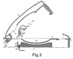
figure 3 shows the handle offigure 2 during its assembly; -
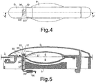
figure 4 shows a front view of the second embodiment of the handle; this embodiment not being covered by the claims; -
figure 5 shows a view cross-sectioned along plane V-V offigure 4 ; -
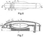
figure 6 shows a front view of the third embodiment of the handle; and -
figure 7 shows a view cross-sectioned along plane VII-VII offigure 6 . - Referring to
figures 1 and 2 , it is seen that the handle according to the first embodiment of the present invention comprises in a known way a frame 1 suitable to be fixed for example behind the outer surface of adoor 2 of a motor vehicle. Frame 1 is provided with atransversal pin 3 acting as a fulcrum, around which a shaped extension 4 of alever 5 suitable for being pulled outwards in the direction ofarrow 6 for openingdoor 2 can rotate.Lever 5 thus rotates around an axis substantially parallel to the rotation axis ofdoor 2. The other end oflever 5 is provided with an appendix 7 which protrudes into frame 1 for the mechanical connection to the unlocking mechanism (not shown in the figures) ofdoor 2, so that the latter can be opened by pullinglever 5.Door 2 and/orlever 5 are shaped for obtainingrecesses 8 and/or 9, respectively, arranged between frame 1 and lever 5 for the hand of the user which must pulllever 5. - According to the invention a
lighting device 10 is fixed to frame 1 and crosses an opening, preferably closed partially by a gasket (not shown in the figures), made in the outer surface ofdoor 2, in particular the same opening crossed by the shaped extension 4 oflever 5. Thelighting device 10 is thus preferably arranged betweenfulcrum 3 and the middle oflever 5, however it could also be arranged close to appendix 7 or in the opening made for the latter in the outer surface ofdoor 2. Theouter portion 10a of thelighting device 10, i.e. the portion outsidedoor 2, protrudes behindlever 5 and is arranged at least partially inrecess 9 oflever 5. Theouter portion 10a of thelighting device 10 is further housed at least partially in aseat 11 which is made inlever 5 and is open toward frame 1.Lever 5 is symmetric with respect to a longitudinal median plane, in particular plane II-II. Thelighting device 10 is crossed by said median plane and itsouter portion 10a is provided with at least onelamp 12 protruding intorecess 9 oflever 5.Lamp 12 is for example a LED mounted on aboard 13 connected by means of conductors to acontrol circuit 14.Board 13 and thecontrol circuit 14 are arranged in the housing of thelighting device 10, which is sealed and completely transparent. Thecontrol circuit 14 is in turn connected to aplug 15 which is provided with gaskets and is suitable for being coupled electrically and mechanically with asocket 16. For this purpose,plug 15 andsocket 16 are provided with a snap-coupling 17 for fixing in a preferably removable manner thelighting member 10 to frame 1. Alsoplug 16 is provided with a snap-coupling 18 for being fixed to frame 1 preferably in a removable manner.Board 13 is substantially parallel to the longitudinal median plane oflever 5, so thatlight 19 emitted bylamp 12 is turned only toward one side of said median plane, in particular downwards. - Referring to
figure 3 , it is seen that during the assembly of the handle according to the present invention thelighting device 10 is inserted for being fixed to frame 1 from the outside ofdoor 2 in atransversal direction 20 with respect to the position of the outer surface ofdoor 2, withlever 5 rotated outwards and with frame 1 already fixed intodoor 2, untilplug 15 andsocket 16 are mutually joined by means of snap-coupling 17. For disassembling thelighting device 10 it is sufficient to insert, a point, for example of a screwdriver, into the opening made indoor 2 for thelighting device 10, so as to unlock snap-coupling 17 and allow the outward extraction of thelighting device 10. - Referring to
figures 4 and 5 , it is seen that the handle according to the second embodiment comprises again alighting device 30 which protrudes intoseat 11 made inlever 5 and crosses an opening made in the outer surface ofdoor 2 for being fixed to frame 1 by means of a snap-coupling 31. Thelighting device 30 is provided with at least onelamp 32 mounted on aboard 33 which includes acontrol circuit 34 and is connected to aplug 35 inserted into asocket 36 which can also be separated from frame 1. Awindow 37 preferably closed by a transparent wall or a prism is made inlever 5 along a surface turned towardrecesses 8 and/or 9, i.e. towarddoor 2, so as to transmit the light emitted bylamp 32 towardrecess 8, as well as upwards and/or downwards, according to the position of obscuring means, if any, arranged onlever 5.Window 37 is arranged besideseat 11 oflever 5.Board 33 is substantially perpendicular to the median plane oflever 5. - Referring to
figures 6 and 7 , it is seen that the handle according to the third embodiment of the present invention comprises alighting device 40 which protrudes intoseat 11 made inlever 5 and which may also be made of a single piece with frame 1. In particular, thelighting device 40 comprises a cavity which is closed by acover 41 and houses twolamps 42, 42' mounted on at least oneboard 43. Thefirst lamp 42 is arranged along the median plane oflever 5 while the second lamp 42' is arranged on a side of this plane, in particular under it. Thelighting device 40 is provided with atransparent portion 44 for transmitting the light emitted bylamps 42, 42' toward at least two, in particular threeoptical guides lever 5 for transmitting said light towardrecesses 8 and/or 9, downwards and upwards, respectively.Lever 5 is provided with anopaque cover 46 provided with awindow 47 arranged in correspondence with the optical guide 45' turned downwards, so as to transmit light downwards, not upwards. For employing the handle according to the third embodiment on the opposite side of a motor vehicle, theopaque cover 46 can be substituted with a similar cover, but provided with a window on the opposite side with respect to the median plane oflever 5, and a board provided with lamps arranged in a specular manner compared withlamps 42, 42' mounted onboard 43 can be inserted into thelighting device 40. - Possible modifications and/or additions may be made by those skilled in the art to the hereinabove disclosed and illustrated embodiments while remaining within the scope of the following claims.
Claims (19)
- Handle comprising a lever (5) and a frame (1) which lever (5) can rotate with respect to said frame (1) to be fixed to the door (2) of a vehicle, which frame (1) is provided with a lighting device (10; 30; 40) for illuminating a space around the handle (2), characterized in that the lighting device (10; 30; 40) is provided with an outer portion (10a) which is housed at least partially in a seat (11) made in the lever (5), wherein the outer portion (10a) of the lighting device (10) is arranged at least partially in a recess (9) which is made in the lever (5) and is arranged between the frame (1) and the lever (5), wherein the outer portion (10a) of the lighting device (10) being provided with at least one lamp (12) protruding into the recess (9) of the lever (5), and wherein the lighting device (10; 30) is fixed to the frame (1) by means of a snap-coupling (17; 31).
- Handle according to the previous claim, characterized in that the rotation axis of the lever (5) is substantially parallel to the rotation axis of the door (2).
- Handle according to the previous claim, characterized in that the lighting device (10; 30) is fixed to the frame (1) in a removable manner.
- Handle according to one of the previous claims, characterized in that the seat (11) of the lever (5) for the lighting device (10; 30; 40) is open toward the frame (1).
- Handle according to one of the previous claims, characterized in that the lighting device (10; 30; 40) is arranged between the fulcrum (3) and the middle of the lever (5).
- Handle according to one of the previous claims, characterized in that the lever (5) is symmetric with respect to a longitudinal median plane.
- Handle according to the previous claim, characterized in that the lighting device (10; 30; 40) is crossed by said median plane.
- Handle according to one of the previous claims, characterized in that at least one portion of the casing of the lighting device (10; 30; 40) is transparent.
- Handle according to one of the previous claims, characterized in that the lighting device (10; 30; 40) is provided with at least one lamp (12; 32; 42, 42') mounted on a board (13; 33; 43).
- Handle according to the previous claim, characterized in that said board (13) is substantially parallel to the longitudinal median plane of the lever (5).
- Handle according to the previous claim, characterized in that the light (19) emitted by the lighting device (10) is turned only toward one side of said median plane.
- Handle according to claim 9, characterized in that said board (33; 43) is substantially perpendicular to the longitudinal median plane of the lever (5).
- Handle according to one of the previous claims, characterized in that the lighting device (10; 30) is provided with a plug (15; 35) suitable for being electrically and mechanically coupled with a socket (16; 36).
- Handle according to the previous claim, characterized in that the socket (16) is provided with a snap-coupling (18) for being fixed to the frame (1).
- Handle according to one of the previous claims, characterized in that the lighting device (10; 30; 40) can be inserted from the outside and fixed to the frame (1) in a transversal direction (20) with respect to the position of outer surface of the door (2).
- Handle according to one of the previous claims, characterized in that the lighting device (40) houses a first lamp (42) arranged along the median plane of the lever (5) and a second lamp (42') arranged on one side of this plane.
- Handle comprising a lever (5) and a frame (1) which lever (5) can rotate with respect to said frame (1) to be fixed to the door (2) of a vehicle, which frame (1) is provided with a lighting device (10; 30; 40) for illuminating a space around the handle (2), characterized in that the lighting device (10; 30; 40) is provided with an outer portion (10a) which is housed at least partially in a seat (11) made in the lever (5), wherein the lever (5) comprises at least two optical guides (45, 45', 45") arranged side by side for transmitting the light emitted by the lighting device (42).
- Handle according to the previous claim, characterized in that the lever (5) comprises three optical guides (45, 45', 45") turned towards a recess (8) made in the door (2) and/or the recess (9) of the lever (5), downwards and upwards, respectively.
- Handle according to the previous claim, characterized in that the lever (5) is provided with an opaque cover (46) provided with at least one window (47) arranged in correspondence with an optical guide (45').
Priority Applications (1)
| Application Number | Priority Date | Filing Date | Title |
|---|---|---|---|
| EP17183581.2A EP3263809B1 (en) | 2007-03-29 | 2008-03-26 | Vehicle handle with a lighting device |
Applications Claiming Priority (2)
| Application Number | Priority Date | Filing Date | Title |
|---|---|---|---|
| IT000629A ITMI20070629A1 (en) | 2007-03-29 | 2007-03-29 | HANDLE FOR VEHICLES WITH ILLUMINATING DEVICE |
| PCT/IB2008/000710 WO2008120067A2 (en) | 2007-03-29 | 2008-03-26 | Vehicle handle with a lighting device |
Related Child Applications (2)
| Application Number | Title | Priority Date | Filing Date |
|---|---|---|---|
| EP17183581.2A Division-Into EP3263809B1 (en) | 2007-03-29 | 2008-03-26 | Vehicle handle with a lighting device |
| EP17183581.2A Division EP3263809B1 (en) | 2007-03-29 | 2008-03-26 | Vehicle handle with a lighting device |
Publications (3)
| Publication Number | Publication Date |
|---|---|
| EP2142730A2 EP2142730A2 (en) | 2010-01-13 |
| EP2142730B1 EP2142730B1 (en) | 2017-08-02 |
| EP2142730B2 true EP2142730B2 (en) | 2020-09-23 |
Family
ID=39777034
Family Applications (2)
| Application Number | Title | Priority Date | Filing Date |
|---|---|---|---|
| EP17183581.2A Active EP3263809B1 (en) | 2007-03-29 | 2008-03-26 | Vehicle handle with a lighting device |
| EP08737341.1A Active EP2142730B2 (en) | 2007-03-29 | 2008-03-26 | Vehicle handle with a lighting device |
Family Applications Before (1)
| Application Number | Title | Priority Date | Filing Date |
|---|---|---|---|
| EP17183581.2A Active EP3263809B1 (en) | 2007-03-29 | 2008-03-26 | Vehicle handle with a lighting device |
Country Status (5)
| Country | Link |
|---|---|
| EP (2) | EP3263809B1 (en) |
| JP (1) | JP5723150B2 (en) |
| CN (1) | CN101646832A (en) |
| IT (1) | ITMI20070629A1 (en) |
| WO (1) | WO2008120067A2 (en) |
Families Citing this family (18)
| Publication number | Priority date | Publication date | Assignee | Title |
|---|---|---|---|---|
| FR2937597B1 (en) * | 2008-10-23 | 2011-07-15 | Valeo Spa | LIGHTING MODULE FOR BELONGING TO A LEVER FOR THE GRIPPING OF A MOTOR VEHICLE OPENING |
| JP5270421B2 (en) * | 2009-03-30 | 2013-08-21 | 株式会社アルファ | Vehicle door handle device |
| DE102010038065A1 (en) * | 2010-10-08 | 2012-04-12 | Huf Hülsbeck & Fürst Gmbh & Co. Kg | Outside door handle device |
| KR101230896B1 (en) * | 2010-11-23 | 2013-02-07 | 현대자동차주식회사 | Illuminator of the door outside handle for vehicle |
| DE102010061643B4 (en) * | 2010-12-30 | 2020-12-17 | Huf Hülsbeck & Fürst Gmbh & Co. Kg | External assembly component for a vehicle with a light module |
| US8985820B2 (en) * | 2012-08-10 | 2015-03-24 | GM Global Technology Operations LLC | Lighted vehicle interior accessory assembly and method |
| DE102012020265B3 (en) * | 2012-10-12 | 2013-11-28 | Audi Ag | Outside door handle assembly for a vehicle door of a vehicle |
| CN103129453A (en) * | 2013-03-26 | 2013-06-05 | 无锡市崇安区科技创业服务中心 | Photosensitive handrail rod for bus |
| DE202013005022U1 (en) * | 2013-05-31 | 2014-09-02 | Kiekert Aktiengesellschaft | Motor vehicle door |
| JP5955302B2 (en) | 2013-11-19 | 2016-07-20 | 株式会社小糸製作所 | Door handle |
| JP5950468B2 (en) * | 2013-11-19 | 2016-07-13 | 株式会社小糸製作所 | Door handle |
| JP6195505B2 (en) | 2013-11-19 | 2017-09-13 | 株式会社小糸製作所 | Door handle |
| DE102014114799A1 (en) * | 2014-10-13 | 2016-04-14 | Huf Hülsbeck & Fürst Gmbh & Co. Kg | Operating handle for a motor vehicle |
| CN106410535B (en) * | 2015-07-29 | 2020-10-02 | 福特环球技术公司 | Base device of electric socket and vehicle interior assembly |
| US9694739B2 (en) * | 2015-11-10 | 2017-07-04 | Ford Global Technologies, Llc | Disinfecting handle |
| JP6392800B2 (en) | 2016-02-26 | 2018-09-19 | 株式会社小糸製作所 | Door handle |
| US10480221B2 (en) * | 2017-07-20 | 2019-11-19 | Magna Closures Inc. | Illuminated virtual handle for power door system in motor vehicles |
| DE102019004707B3 (en) * | 2019-07-04 | 2020-10-22 | Daimler Ag | Door handle for a vehicle door |
Citations (4)
| Publication number | Priority date | Publication date | Assignee | Title |
|---|---|---|---|---|
| US4467402A (en) † | 1980-05-03 | 1984-08-21 | Daimler-Benz Ag | Vehicle lock illuminating system |
| DE4212291A1 (en) † | 1992-04-11 | 1993-10-14 | Daimler Benz Ag | Vehicle door lock arrangement - triggers electrical switch operation to open door manually and monitors lock user's fingers |
| DE29921248U1 (en) † | 1999-12-02 | 2000-03-30 | Fehrenbacher Alfred | Door opener lighting for motor vehicles |
| DE19843594A1 (en) † | 1998-09-23 | 2000-04-06 | Valeo Gmbh & Co Schliessyst Kg | Door handle for vehicle door which includes bearing bracket fixable at door and handle part swivelable at bracket with extension projecting inside of door |
Family Cites Families (22)
| Publication number | Priority date | Publication date | Assignee | Title |
|---|---|---|---|---|
| US5297010A (en) | 1992-08-28 | 1994-03-22 | Itc Incorporated | Illuminated grab handle |
| JPH11105547A (en) | 1997-10-03 | 1999-04-20 | Kojima Press Co Ltd | Compartment side door handle display illuminator |
| DE19757085A1 (en) | 1997-12-20 | 1999-06-24 | Hella Kg Hueck & Co | Device for illuminating an apron of a vehicle part |
| FR2772818B1 (en) | 1997-12-23 | 2000-01-21 | Valeo Securite Habitacle | SECURITY SYSTEM FOR A MOTOR VEHICLE OPENING ELEMENT |
| US6070998A (en) * | 1998-01-23 | 2000-06-06 | General Motors Corporation | Fiber optic lighting system for vehicle door handle |
| DE19809716A1 (en) | 1998-03-06 | 1999-09-09 | Hella Kg Hueck & Co | Illumination device for area in front of automobile passenger door |
| DE19813782C1 (en) | 1998-03-27 | 1999-05-06 | Siemens Ag | Access control unit for motor vehicle |
| DE19822733C2 (en) | 1998-05-20 | 2001-05-10 | Bayerische Motoren Werke Ag | Device for illuminating the apron on the side of a vehicle |
| DE19928201A1 (en) | 1999-06-19 | 2000-12-21 | Hella Kg Hueck & Co | Device for illuminating an apron of an openable vehicle part |
| DE19947752A1 (en) | 1999-10-02 | 2001-03-22 | Daimler Chrysler Ag | Illumination system for gripping section of door opening unit provided for gripping with one or several fingers which serves for opening of vehicle door |
| EP1609974B1 (en) | 1999-11-09 | 2008-08-20 | Honda Giken Kogyo Kabushiki Kaisha | Control system for internal combustion engine |
| DE10039685A1 (en) | 2000-08-14 | 2002-02-28 | Volkswagen Ag | Method for fitting a motor vehicle with lights for aiding orientation during darkness integrates lights in vehicle door handles containing a phosphor surface for an indicator light and for illuminating outer foot space. |
| JP2002240626A (en) | 2001-02-19 | 2002-08-28 | Toyoda Gosei Co Ltd | Door lever device for vehicle |
| JP4176970B2 (en) | 2001-03-28 | 2008-11-05 | 株式会社アルファ | Object detection apparatus and object detection method |
| DE10121046A1 (en) | 2001-04-28 | 2002-11-07 | Huf Huelsbeck & Fuerst Gmbh | External actuation for vehicle locks on doors, flaps or the like. |
| US6848818B2 (en) | 2001-10-24 | 2005-02-01 | Donnelly Corporation | Vehicle handle assembly with cup lighting |
| DE10303514A1 (en) | 2003-01-30 | 2004-08-12 | Bayerische Motoren Werke Ag | Lighting device on a vehicle door |
| JP2005163295A (en) * | 2003-11-28 | 2005-06-23 | Alpha Corp | Door opening/closing device |
| JP4535762B2 (en) * | 2004-03-30 | 2010-09-01 | 株式会社ホンダロック | Vehicle door handle device |
| JP4257601B2 (en) * | 2004-06-24 | 2009-04-22 | アイシン精機株式会社 | Vehicle door opening and closing device |
| JP2006137330A (en) * | 2004-11-12 | 2006-06-01 | Toyoda Gosei Co Ltd | Outside handle for vehicle |
| TWM289136U (en) | 2005-09-30 | 2006-04-01 | Yu Lin Plastics Entpr Co Ltd | Improved structure of illuminating handle of automobiles/motorcycles |
-
2007
- 2007-03-29 IT IT000629A patent/ITMI20070629A1/en unknown
-
2008
- 2008-03-26 EP EP17183581.2A patent/EP3263809B1/en active Active
- 2008-03-26 WO PCT/IB2008/000710 patent/WO2008120067A2/en active Application Filing
- 2008-03-26 CN CN200880010312A patent/CN101646832A/en active Pending
- 2008-03-26 JP JP2010500379A patent/JP5723150B2/en active Active
- 2008-03-26 EP EP08737341.1A patent/EP2142730B2/en active Active
Patent Citations (4)
| Publication number | Priority date | Publication date | Assignee | Title |
|---|---|---|---|---|
| US4467402A (en) † | 1980-05-03 | 1984-08-21 | Daimler-Benz Ag | Vehicle lock illuminating system |
| DE4212291A1 (en) † | 1992-04-11 | 1993-10-14 | Daimler Benz Ag | Vehicle door lock arrangement - triggers electrical switch operation to open door manually and monitors lock user's fingers |
| DE19843594A1 (en) † | 1998-09-23 | 2000-04-06 | Valeo Gmbh & Co Schliessyst Kg | Door handle for vehicle door which includes bearing bracket fixable at door and handle part swivelable at bracket with extension projecting inside of door |
| DE29921248U1 (en) † | 1999-12-02 | 2000-03-30 | Fehrenbacher Alfred | Door opener lighting for motor vehicles |
Also Published As
| Publication number | Publication date |
|---|---|
| CN101646832A (en) | 2010-02-10 |
| JP5723150B2 (en) | 2015-05-27 |
| EP2142730B1 (en) | 2017-08-02 |
| ITMI20070629A1 (en) | 2008-09-30 |
| EP2142730A2 (en) | 2010-01-13 |
| WO2008120067A3 (en) | 2008-12-11 |
| WO2008120067A2 (en) | 2008-10-09 |
| JP2010522661A (en) | 2010-07-08 |
| EP3263809A1 (en) | 2018-01-03 |
| EP3263809B1 (en) | 2019-02-06 |
Similar Documents
| Publication | Publication Date | Title |
|---|---|---|
| EP2142730B2 (en) | Vehicle handle with a lighting device | |
| CN107109856B (en) | LED ring for electromechanical locking system | |
| KR20160137922A (en) | Handle assembly for a motor vehicle door | |
| CN102537808B (en) | For the lighting device of the door outside handle of vehicle | |
| US8833813B2 (en) | Handle device | |
| WO2009023413A3 (en) | Electric current conduction system for appliance | |
| CN104134561A (en) | Metal key module, control box module with metal key module, and range hood | |
| CN105144328A (en) | Lighting switch for display unit | |
| KR100613552B1 (en) | Exterior mirror with turn signal lamp | |
| JP2005163295A (en) | Door opening/closing device | |
| US7355135B2 (en) | Switch panel having at least one switch | |
| JP5561878B2 (en) | Slot machine | |
| EP2848470B1 (en) | Sunshade assembly comprising electric switching means | |
| KR200425707Y1 (en) | Power supply device for vehicle | |
| KR101063220B1 (en) | Illumination of door outside handle | |
| WO2008072131A3 (en) | Electric reflector lamp | |
| CN101101339A (en) | Adjustable light barrier member | |
| CN203300477U (en) | Metallic button assembly and control body assembly employing same and smoke ventilator employing control body assembly | |
| KR100717737B1 (en) | Diplay apparatus of operating state of Electric actuater | |
| CN211289753U (en) | Lamp fitting | |
| TWI470661B (en) | Switch | |
| KR20100006423U (en) | Vehiclular room lamp unit | |
| WO2005100848A8 (en) | Luminaires | |
| CN114654977A (en) | Motor vehicle tailgate with a simplified installation of a device support tray | |
| KR100726495B1 (en) | Headlamp aiming apparatus |
Legal Events
| Date | Code | Title | Description |
|---|---|---|---|
| PUAI | Public reference made under article 153(3) epc to a published international application that has entered the european phase |
Free format text: ORIGINAL CODE: 0009012 |
|
| 17P | Request for examination filed |
Effective date: 20091029 |
|
| AK | Designated contracting states |
Kind code of ref document: A2 Designated state(s): AT BE BG CH CY CZ DE DK EE ES FI FR GB GR HR HU IE IS IT LI LT LU LV MC MT NL NO PL PT RO SE SI SK TR |
|
| DAX | Request for extension of the european patent (deleted) | ||
| RAP1 | Party data changed (applicant data changed or rights of an application transferred) |
Owner name: U-SHIN ITALIA S.P.A. |
|
| REG | Reference to a national code |
Ref country code: DE Ref legal event code: R079 Ref document number: 602008051387 Country of ref document: DE Free format text: PREVIOUS MAIN CLASS: E05B0017100000 Ipc: E05B0085160000 |
|
| GRAP | Despatch of communication of intention to grant a patent |
Free format text: ORIGINAL CODE: EPIDOSNIGR1 |
|
| STAA | Information on the status of an ep patent application or granted ep patent |
Free format text: STATUS: GRANT OF PATENT IS INTENDED |
|
| RIC1 | Information provided on ipc code assigned before grant |
Ipc: B60Q 1/32 20060101ALI20170125BHEP Ipc: B60Q 1/26 20060101ALI20170125BHEP Ipc: E05B 85/16 20140101AFI20170125BHEP Ipc: E05B 17/10 20060101ALI20170125BHEP |
|
| INTG | Intention to grant announced |
Effective date: 20170216 |
|
| GRAS | Grant fee paid |
Free format text: ORIGINAL CODE: EPIDOSNIGR3 |
|
| GRAA | (expected) grant |
Free format text: ORIGINAL CODE: 0009210 |
|
| STAA | Information on the status of an ep patent application or granted ep patent |
Free format text: STATUS: THE PATENT HAS BEEN GRANTED |
|
| AK | Designated contracting states |
Kind code of ref document: B1 Designated state(s): AT BE BG CH CY CZ DE DK EE ES FI FR GB GR HR HU IE IS IT LI LT LU LV MC MT NL NO PL PT RO SE SI SK TR |
|
| REG | Reference to a national code |
Ref country code: GB Ref legal event code: FG4D |
|
| REG | Reference to a national code |
Ref country code: CH Ref legal event code: EP Ref country code: AT Ref legal event code: REF Ref document number: 914661 Country of ref document: AT Kind code of ref document: T Effective date: 20170815 |
|
| REG | Reference to a national code |
Ref country code: IE Ref legal event code: FG4D |
|
| REG | Reference to a national code |
Ref country code: DE Ref legal event code: R096 Ref document number: 602008051387 Country of ref document: DE |
|
| REG | Reference to a national code |
Ref country code: NL Ref legal event code: MP Effective date: 20170802 |
|
| REG | Reference to a national code |
Ref country code: AT Ref legal event code: MK05 Ref document number: 914661 Country of ref document: AT Kind code of ref document: T Effective date: 20170802 |
|
| REG | Reference to a national code |
Ref country code: LT Ref legal event code: MG4D |
|
| PG25 | Lapsed in a contracting state [announced via postgrant information from national office to epo] |
Ref country code: HR Free format text: LAPSE BECAUSE OF FAILURE TO SUBMIT A TRANSLATION OF THE DESCRIPTION OR TO PAY THE FEE WITHIN THE PRESCRIBED TIME-LIMIT Effective date: 20170802 Ref country code: NL Free format text: LAPSE BECAUSE OF FAILURE TO SUBMIT A TRANSLATION OF THE DESCRIPTION OR TO PAY THE FEE WITHIN THE PRESCRIBED TIME-LIMIT Effective date: 20170802 Ref country code: LT Free format text: LAPSE BECAUSE OF FAILURE TO SUBMIT A TRANSLATION OF THE DESCRIPTION OR TO PAY THE FEE WITHIN THE PRESCRIBED TIME-LIMIT Effective date: 20170802 Ref country code: FI Free format text: LAPSE BECAUSE OF FAILURE TO SUBMIT A TRANSLATION OF THE DESCRIPTION OR TO PAY THE FEE WITHIN THE PRESCRIBED TIME-LIMIT Effective date: 20170802 Ref country code: SE Free format text: LAPSE BECAUSE OF FAILURE TO SUBMIT A TRANSLATION OF THE DESCRIPTION OR TO PAY THE FEE WITHIN THE PRESCRIBED TIME-LIMIT Effective date: 20170802 Ref country code: AT Free format text: LAPSE BECAUSE OF FAILURE TO SUBMIT A TRANSLATION OF THE DESCRIPTION OR TO PAY THE FEE WITHIN THE PRESCRIBED TIME-LIMIT Effective date: 20170802 Ref country code: NO Free format text: LAPSE BECAUSE OF FAILURE TO SUBMIT A TRANSLATION OF THE DESCRIPTION OR TO PAY THE FEE WITHIN THE PRESCRIBED TIME-LIMIT Effective date: 20171102 |
|
| PG25 | Lapsed in a contracting state [announced via postgrant information from national office to epo] |
Ref country code: GR Free format text: LAPSE BECAUSE OF FAILURE TO SUBMIT A TRANSLATION OF THE DESCRIPTION OR TO PAY THE FEE WITHIN THE PRESCRIBED TIME-LIMIT Effective date: 20171103 Ref country code: ES Free format text: LAPSE BECAUSE OF FAILURE TO SUBMIT A TRANSLATION OF THE DESCRIPTION OR TO PAY THE FEE WITHIN THE PRESCRIBED TIME-LIMIT Effective date: 20170802 Ref country code: IS Free format text: LAPSE BECAUSE OF FAILURE TO SUBMIT A TRANSLATION OF THE DESCRIPTION OR TO PAY THE FEE WITHIN THE PRESCRIBED TIME-LIMIT Effective date: 20171202 Ref country code: BG Free format text: LAPSE BECAUSE OF FAILURE TO SUBMIT A TRANSLATION OF THE DESCRIPTION OR TO PAY THE FEE WITHIN THE PRESCRIBED TIME-LIMIT Effective date: 20171102 Ref country code: PL Free format text: LAPSE BECAUSE OF FAILURE TO SUBMIT A TRANSLATION OF THE DESCRIPTION OR TO PAY THE FEE WITHIN THE PRESCRIBED TIME-LIMIT Effective date: 20170802 Ref country code: LV Free format text: LAPSE BECAUSE OF FAILURE TO SUBMIT A TRANSLATION OF THE DESCRIPTION OR TO PAY THE FEE WITHIN THE PRESCRIBED TIME-LIMIT Effective date: 20170802 |
|
| REG | Reference to a national code |
Ref country code: FR Ref legal event code: PLFP Year of fee payment: 11 |
|
| PG25 | Lapsed in a contracting state [announced via postgrant information from national office to epo] |
Ref country code: DK Free format text: LAPSE BECAUSE OF FAILURE TO SUBMIT A TRANSLATION OF THE DESCRIPTION OR TO PAY THE FEE WITHIN THE PRESCRIBED TIME-LIMIT Effective date: 20170802 Ref country code: CZ Free format text: LAPSE BECAUSE OF FAILURE TO SUBMIT A TRANSLATION OF THE DESCRIPTION OR TO PAY THE FEE WITHIN THE PRESCRIBED TIME-LIMIT Effective date: 20170802 Ref country code: RO Free format text: LAPSE BECAUSE OF FAILURE TO SUBMIT A TRANSLATION OF THE DESCRIPTION OR TO PAY THE FEE WITHIN THE PRESCRIBED TIME-LIMIT Effective date: 20170802 |
|
| REG | Reference to a national code |
Ref country code: DE Ref legal event code: R026 Ref document number: 602008051387 Country of ref document: DE |
|
| PLBI | Opposition filed |
Free format text: ORIGINAL CODE: 0009260 |
|
| PLAX | Notice of opposition and request to file observation + time limit sent |
Free format text: ORIGINAL CODE: EPIDOSNOBS2 |
|
| PG25 | Lapsed in a contracting state [announced via postgrant information from national office to epo] |
Ref country code: SK Free format text: LAPSE BECAUSE OF FAILURE TO SUBMIT A TRANSLATION OF THE DESCRIPTION OR TO PAY THE FEE WITHIN THE PRESCRIBED TIME-LIMIT Effective date: 20170802 Ref country code: EE Free format text: LAPSE BECAUSE OF FAILURE TO SUBMIT A TRANSLATION OF THE DESCRIPTION OR TO PAY THE FEE WITHIN THE PRESCRIBED TIME-LIMIT Effective date: 20170802 |
|
| 26 | Opposition filed |
Opponent name: HUF HUELSBECK & FUERST GMBH & CO. KG Effective date: 20180502 |
|
| PG25 | Lapsed in a contracting state [announced via postgrant information from national office to epo] |
Ref country code: SI Free format text: LAPSE BECAUSE OF FAILURE TO SUBMIT A TRANSLATION OF THE DESCRIPTION OR TO PAY THE FEE WITHIN THE PRESCRIBED TIME-LIMIT Effective date: 20170802 |
|
| PLBB | Reply of patent proprietor to notice(s) of opposition received |
Free format text: ORIGINAL CODE: EPIDOSNOBS3 |
|
| REG | Reference to a national code |
Ref country code: CH Ref legal event code: PL |
|
| PG25 | Lapsed in a contracting state [announced via postgrant information from national office to epo] |
Ref country code: MC Free format text: LAPSE BECAUSE OF FAILURE TO SUBMIT A TRANSLATION OF THE DESCRIPTION OR TO PAY THE FEE WITHIN THE PRESCRIBED TIME-LIMIT Effective date: 20170802 |
|
| REG | Reference to a national code |
Ref country code: BE Ref legal event code: MM Effective date: 20180331 |
|
| REG | Reference to a national code |
Ref country code: IE Ref legal event code: MM4A |
|
| PG25 | Lapsed in a contracting state [announced via postgrant information from national office to epo] |
Ref country code: LU Free format text: LAPSE BECAUSE OF NON-PAYMENT OF DUE FEES Effective date: 20180326 |
|
| PG25 | Lapsed in a contracting state [announced via postgrant information from national office to epo] |
Ref country code: IE Free format text: LAPSE BECAUSE OF NON-PAYMENT OF DUE FEES Effective date: 20180326 |
|
| PG25 | Lapsed in a contracting state [announced via postgrant information from national office to epo] |
Ref country code: CH Free format text: LAPSE BECAUSE OF NON-PAYMENT OF DUE FEES Effective date: 20180331 Ref country code: LI Free format text: LAPSE BECAUSE OF NON-PAYMENT OF DUE FEES Effective date: 20180331 Ref country code: BE Free format text: LAPSE BECAUSE OF NON-PAYMENT OF DUE FEES Effective date: 20180331 |
|
| APBM | Appeal reference recorded |
Free format text: ORIGINAL CODE: EPIDOSNREFNO |
|
| APBP | Date of receipt of notice of appeal recorded |
Free format text: ORIGINAL CODE: EPIDOSNNOA2O |
|
| APAH | Appeal reference modified |
Free format text: ORIGINAL CODE: EPIDOSCREFNO |
|
| PG25 | Lapsed in a contracting state [announced via postgrant information from national office to epo] |
Ref country code: MT Free format text: LAPSE BECAUSE OF NON-PAYMENT OF DUE FEES Effective date: 20180326 |
|
| APBU | Appeal procedure closed |
Free format text: ORIGINAL CODE: EPIDOSNNOA9O |
|
| PG25 | Lapsed in a contracting state [announced via postgrant information from national office to epo] |
Ref country code: TR Free format text: LAPSE BECAUSE OF FAILURE TO SUBMIT A TRANSLATION OF THE DESCRIPTION OR TO PAY THE FEE WITHIN THE PRESCRIBED TIME-LIMIT Effective date: 20170802 |
|
| PG25 | Lapsed in a contracting state [announced via postgrant information from national office to epo] |
Ref country code: HU Free format text: LAPSE BECAUSE OF FAILURE TO SUBMIT A TRANSLATION OF THE DESCRIPTION OR TO PAY THE FEE WITHIN THE PRESCRIBED TIME-LIMIT; INVALID AB INITIO Effective date: 20080326 Ref country code: PT Free format text: LAPSE BECAUSE OF FAILURE TO SUBMIT A TRANSLATION OF THE DESCRIPTION OR TO PAY THE FEE WITHIN THE PRESCRIBED TIME-LIMIT Effective date: 20170802 |
|
| PG25 | Lapsed in a contracting state [announced via postgrant information from national office to epo] |
Ref country code: CY Free format text: LAPSE BECAUSE OF FAILURE TO SUBMIT A TRANSLATION OF THE DESCRIPTION OR TO PAY THE FEE WITHIN THE PRESCRIBED TIME-LIMIT Effective date: 20170802 |
|
| PUAH | Patent maintained in amended form |
Free format text: ORIGINAL CODE: 0009272 |
|
| STAA | Information on the status of an ep patent application or granted ep patent |
Free format text: STATUS: PATENT MAINTAINED AS AMENDED |
|
| 27A | Patent maintained in amended form |
Effective date: 20200923 |
|
| AK | Designated contracting states |
Kind code of ref document: B2 Designated state(s): AT BE BG CH CY CZ DE DK EE ES FI FR GB GR HR HU IE IS IT LI LT LU LV MC MT NL NO PL PT RO SE SI SK TR |
|
| REG | Reference to a national code |
Ref country code: DE Ref legal event code: R102 Ref document number: 602008051387 Country of ref document: DE |
|
| PGFP | Annual fee paid to national office [announced via postgrant information from national office to epo] |
Ref country code: FR Payment date: 20230320 Year of fee payment: 16 |
|
| PGFP | Annual fee paid to national office [announced via postgrant information from national office to epo] |
Ref country code: IT Payment date: 20230308 Year of fee payment: 16 |
|
| PGFP | Annual fee paid to national office [announced via postgrant information from national office to epo] |
Ref country code: DE Payment date: 20240307 Year of fee payment: 17 Ref country code: GB Payment date: 20240325 Year of fee payment: 17 |