EP2141760A1 - Elektrode für einen Energiespeicher - Google Patents
Elektrode für einen Energiespeicher Download PDFInfo
- Publication number
- EP2141760A1 EP2141760A1 EP09008770A EP09008770A EP2141760A1 EP 2141760 A1 EP2141760 A1 EP 2141760A1 EP 09008770 A EP09008770 A EP 09008770A EP 09008770 A EP09008770 A EP 09008770A EP 2141760 A1 EP2141760 A1 EP 2141760A1
- Authority
- EP
- European Patent Office
- Prior art keywords
- electrode
- alloy
- energy store
- tin
- electrodes
- Prior art date
- Legal status (The legal status is an assumption and is not a legal conclusion. Google has not performed a legal analysis and makes no representation as to the accuracy of the status listed.)
- Granted
Links
- RYGMFSIKBFXOCR-UHFFFAOYSA-N Copper Chemical compound [Cu] RYGMFSIKBFXOCR-UHFFFAOYSA-N 0.000 claims abstract description 26
- 229910045601 alloy Inorganic materials 0.000 claims abstract description 26
- 239000000956 alloy Substances 0.000 claims abstract description 26
- 238000004146 energy storage Methods 0.000 claims abstract description 26
- ATJFFYVFTNAWJD-UHFFFAOYSA-N Tin Chemical compound [Sn] ATJFFYVFTNAWJD-UHFFFAOYSA-N 0.000 claims abstract description 23
- 239000007772 electrode material Substances 0.000 claims abstract description 23
- 229910052802 copper Inorganic materials 0.000 claims abstract description 21
- 239000010949 copper Substances 0.000 claims abstract description 21
- 239000013078 crystal Substances 0.000 claims abstract description 11
- 229910001416 lithium ion Inorganic materials 0.000 claims abstract description 11
- WHXSMMKQMYFTQS-UHFFFAOYSA-N Lithium Chemical compound [Li] WHXSMMKQMYFTQS-UHFFFAOYSA-N 0.000 claims abstract description 5
- 229910052744 lithium Inorganic materials 0.000 claims abstract description 5
- HBBGRARXTFLTSG-UHFFFAOYSA-N Lithium ion Chemical compound [Li+] HBBGRARXTFLTSG-UHFFFAOYSA-N 0.000 claims abstract description 4
- 239000003792 electrolyte Substances 0.000 claims description 8
- 239000003990 capacitor Substances 0.000 claims description 3
- 239000000463 material Substances 0.000 abstract description 11
- 229910052718 tin Inorganic materials 0.000 description 10
- 239000000126 substance Substances 0.000 description 4
- 239000004020 conductor Substances 0.000 description 3
- 150000002500 ions Chemical class 0.000 description 3
- 230000007774 longterm Effects 0.000 description 3
- OKTJSMMVPCPJKN-UHFFFAOYSA-N Carbon Chemical compound [C] OKTJSMMVPCPJKN-UHFFFAOYSA-N 0.000 description 2
- 239000003795 chemical substances by application Substances 0.000 description 2
- 150000001879 copper Chemical class 0.000 description 2
- 230000007797 corrosion Effects 0.000 description 2
- 238000005260 corrosion Methods 0.000 description 2
- 230000001419 dependent effect Effects 0.000 description 2
- 238000011161 development Methods 0.000 description 2
- 230000018109 developmental process Effects 0.000 description 2
- 229910002804 graphite Inorganic materials 0.000 description 2
- 239000010439 graphite Substances 0.000 description 2
- 238000000034 method Methods 0.000 description 2
- 238000007711 solidification Methods 0.000 description 2
- 230000008023 solidification Effects 0.000 description 2
- 230000035882 stress Effects 0.000 description 2
- 229910000881 Cu alloy Inorganic materials 0.000 description 1
- 238000010521 absorption reaction Methods 0.000 description 1
- 230000032683 aging Effects 0.000 description 1
- 229910052782 aluminium Inorganic materials 0.000 description 1
- XAGFODPZIPBFFR-UHFFFAOYSA-N aluminium Chemical compound [Al] XAGFODPZIPBFFR-UHFFFAOYSA-N 0.000 description 1
- 239000010405 anode material Substances 0.000 description 1
- 230000015572 biosynthetic process Effects 0.000 description 1
- 235000019577 caloric intake Nutrition 0.000 description 1
- 239000006182 cathode active material Substances 0.000 description 1
- 238000006243 chemical reaction Methods 0.000 description 1
- 238000010276 construction Methods 0.000 description 1
- 238000005336 cracking Methods 0.000 description 1
- 238000007599 discharging Methods 0.000 description 1
- 239000010416 ion conductor Substances 0.000 description 1
- 239000007788 liquid Substances 0.000 description 1
- 238000004519 manufacturing process Methods 0.000 description 1
- 229910052751 metal Inorganic materials 0.000 description 1
- 239000002184 metal Substances 0.000 description 1
- 239000000203 mixture Substances 0.000 description 1
- 230000002441 reversible effect Effects 0.000 description 1
- 239000007787 solid Substances 0.000 description 1
Images
Classifications
-
- H—ELECTRICITY
- H01—ELECTRIC ELEMENTS
- H01M—PROCESSES OR MEANS, e.g. BATTERIES, FOR THE DIRECT CONVERSION OF CHEMICAL ENERGY INTO ELECTRICAL ENERGY
- H01M4/00—Electrodes
- H01M4/02—Electrodes composed of, or comprising, active material
- H01M4/64—Carriers or collectors
- H01M4/66—Selection of materials
- H01M4/661—Metal or alloys, e.g. alloy coatings
-
- H—ELECTRICITY
- H01—ELECTRIC ELEMENTS
- H01G—CAPACITORS; CAPACITORS, RECTIFIERS, DETECTORS, SWITCHING DEVICES, LIGHT-SENSITIVE OR TEMPERATURE-SENSITIVE DEVICES OF THE ELECTROLYTIC TYPE
- H01G11/00—Hybrid capacitors, i.e. capacitors having different positive and negative electrodes; Electric double-layer [EDL] capacitors; Processes for the manufacture thereof or of parts thereof
- H01G11/22—Electrodes
- H01G11/26—Electrodes characterised by their structure, e.g. multi-layered, porosity or surface features
- H01G11/28—Electrodes characterised by their structure, e.g. multi-layered, porosity or surface features arranged or disposed on a current collector; Layers or phases between electrodes and current collectors, e.g. adhesives
-
- H—ELECTRICITY
- H01—ELECTRIC ELEMENTS
- H01G—CAPACITORS; CAPACITORS, RECTIFIERS, DETECTORS, SWITCHING DEVICES, LIGHT-SENSITIVE OR TEMPERATURE-SENSITIVE DEVICES OF THE ELECTROLYTIC TYPE
- H01G11/00—Hybrid capacitors, i.e. capacitors having different positive and negative electrodes; Electric double-layer [EDL] capacitors; Processes for the manufacture thereof or of parts thereof
- H01G11/22—Electrodes
- H01G11/30—Electrodes characterised by their material
- H01G11/50—Electrodes characterised by their material specially adapted for lithium-ion capacitors, e.g. for lithium-doping or for intercalation
-
- H—ELECTRICITY
- H01—ELECTRIC ELEMENTS
- H01M—PROCESSES OR MEANS, e.g. BATTERIES, FOR THE DIRECT CONVERSION OF CHEMICAL ENERGY INTO ELECTRICAL ENERGY
- H01M10/00—Secondary cells; Manufacture thereof
- H01M10/05—Accumulators with non-aqueous electrolyte
- H01M10/052—Li-accumulators
-
- H—ELECTRICITY
- H01—ELECTRIC ELEMENTS
- H01M—PROCESSES OR MEANS, e.g. BATTERIES, FOR THE DIRECT CONVERSION OF CHEMICAL ENERGY INTO ELECTRICAL ENERGY
- H01M4/00—Electrodes
- H01M4/02—Electrodes composed of, or comprising, active material
- H01M4/64—Carriers or collectors
- H01M4/66—Selection of materials
- H01M4/663—Selection of materials containing carbon or carbonaceous materials as conductive part, e.g. graphite, carbon fibres
-
- Y—GENERAL TAGGING OF NEW TECHNOLOGICAL DEVELOPMENTS; GENERAL TAGGING OF CROSS-SECTIONAL TECHNOLOGIES SPANNING OVER SEVERAL SECTIONS OF THE IPC; TECHNICAL SUBJECTS COVERED BY FORMER USPC CROSS-REFERENCE ART COLLECTIONS [XRACs] AND DIGESTS
- Y02—TECHNOLOGIES OR APPLICATIONS FOR MITIGATION OR ADAPTATION AGAINST CLIMATE CHANGE
- Y02E—REDUCTION OF GREENHOUSE GAS [GHG] EMISSIONS, RELATED TO ENERGY GENERATION, TRANSMISSION OR DISTRIBUTION
- Y02E60/00—Enabling technologies; Technologies with a potential or indirect contribution to GHG emissions mitigation
- Y02E60/10—Energy storage using batteries
-
- Y—GENERAL TAGGING OF NEW TECHNOLOGICAL DEVELOPMENTS; GENERAL TAGGING OF CROSS-SECTIONAL TECHNOLOGIES SPANNING OVER SEVERAL SECTIONS OF THE IPC; TECHNICAL SUBJECTS COVERED BY FORMER USPC CROSS-REFERENCE ART COLLECTIONS [XRACs] AND DIGESTS
- Y02—TECHNOLOGIES OR APPLICATIONS FOR MITIGATION OR ADAPTATION AGAINST CLIMATE CHANGE
- Y02E—REDUCTION OF GREENHOUSE GAS [GHG] EMISSIONS, RELATED TO ENERGY GENERATION, TRANSMISSION OR DISTRIBUTION
- Y02E60/00—Enabling technologies; Technologies with a potential or indirect contribution to GHG emissions mitigation
- Y02E60/13—Energy storage using capacitors
-
- Y—GENERAL TAGGING OF NEW TECHNOLOGICAL DEVELOPMENTS; GENERAL TAGGING OF CROSS-SECTIONAL TECHNOLOGIES SPANNING OVER SEVERAL SECTIONS OF THE IPC; TECHNICAL SUBJECTS COVERED BY FORMER USPC CROSS-REFERENCE ART COLLECTIONS [XRACs] AND DIGESTS
- Y02—TECHNOLOGIES OR APPLICATIONS FOR MITIGATION OR ADAPTATION AGAINST CLIMATE CHANGE
- Y02T—CLIMATE CHANGE MITIGATION TECHNOLOGIES RELATED TO TRANSPORTATION
- Y02T10/00—Road transport of goods or passengers
- Y02T10/60—Other road transportation technologies with climate change mitigation effect
- Y02T10/70—Energy storage systems for electromobility, e.g. batteries
Definitions
- the present invention relates to an electrode for an energy store and an energy store with such an electrode.
- the invention will be described in the context of lithium-ion batteries for driving electric vehicles or hybrid electric vehicles. It should be noted that the invention can also be applied to batteries with deviating chemistry or independently of the use of the battery for the supply of the drive of an electric vehicle or hybrid electric vehicle application.
- Energy storage is increasingly used in electric vehicles and electric hybrid vehicles, which is why there is an increasing demand for energy storage with a large capacity, high performance and long-term stability.
- the lithium (ion) cells occupy a special position, especially as secondary cells, due to their high specific energy storage density.
- An example of a layered lithium ion cell is in DE 10 2005 042 916 A1 and an example of a wound lithium-ion cell is disclosed in U.S.P. EP 0 949 699 B1 disclosed.
- the energy accumulator embodied here as a lithium-ion cell contains in each case a first electrode, a second electrode and a separating element between the first and the second electrode or an arrangement of these components stacked alternately one over the other.
- the electrodes are usually formed from an electrode carrier, on the one or both sides of an active electrode material is applied.
- the anode is often made of an anode support made of copper and an active anode material such as graphite, and the cathode is common formed of an aluminum cathode support and an active cathode material of lithiated oxides.
- the present invention has for its object to provide an energy storage device with improved long-term stability or an electrode for such energy storage.
- the object is achieved by an electrode for an energy store having the features of claim 1.
- Advantageous embodiments and further developments of the invention are subject matter of the dependent claims 2 to 7.
- An energy storage device with an electrode according to the invention is described in claims 8 to 15.
- the electrode for an energy store contains an electrode carrier and an active electrode material which is applied to the electrode carrier on one or both sides.
- the electrode carrier is formed from an alloy with a copper content, this alloy additionally having at least tin with a content of at least about 0.01% by weight.
- the aforementioned electrode is used to store energy.
- This electrode stores the energy in chemical form. To deliver electrical energy, it is converted from chemically stored energy. Depending on the design of the electrode, this is suitable for only single discharge or for energy absorption. During the energy intake, such as a charge, this energy is supplied in electrical form and converted into chemical energy.
- the electrode is in at least electrical operative connection with an electrolyte and a supply conductor.
- the aforementioned energy storage is used to supply a drive of an electric vehicle or an electric hybrid vehicle.
- This energy storage can also supply other drives or consumers. If the energy storage only serves for a single delivery of electrical energy, it is called a primary cell or battery. Depending on the training can this energy storage also absorb electrical energy, for example by charging. In this case we speak of a secondary cell or an accumulator.
- electrical energy is converted into chemical energy and vice versa. This energy conversion involves two electrodes and one electrolyte. With each of these electrodes, a separate supply conductor is electrically connected. These feeders are in turn electrically connected to a consumer, for example to the drive of a motor vehicle.
- the aforementioned electrode has an electrode carrier.
- This electrode carrier is an electrically conductive solid.
- This electrode carrier preferably has at least one metal or graphite, according to the invention an alloy with the participation of at least copper and tin.
- the electrode carrier has at least one crystal lattice, in practice a plurality of crystal lattices.
- the electrode carrier conducts electrons from this active electrode material via the feed line to the consumer and also in the opposite direction.
- the aforementioned electrode further comprises active electrode material.
- the active electrode material is a substance mixture which is, for example, paste-like. This active electrode material is in operative connection with the electrolyte. Between these two there is also the exchange of ions.
- the active electrode material is applied to one side or both sides of the electrode carrier and is in electrical operative connection with this. Electrons are transferred by conduction between electrode carrier and active electrode material.
- the electrode carrier is formed of an electrically conductive alloy. which predominantly comprises copper and tin with a content of at least about 0.01% by weight.
- the solidified alloy has a plurality of crystal lattices. Upon solidification of liquid copper, the individual copper atoms form a preferred crystal lattice form. Existing tin atoms replace single copper atoms in its crystal lattice. A certain volume of Material thus has predominantly copper atoms and a certain number of tin atoms as so-called foreign atoms.
- the electrode formed as described above is therefore particularly suitable for large-sized energy storage devices with a large capacity and high performance, as required for example for electric vehicles and electric hybrid vehicles.
- the alloy for this electrode carrier is prepared so that the copper contained forms the largest weight fraction of this alloy.
- the alloy preferably comprises mixed crystals of copper and tin.
- these mixed crystals a certain number of copper atoms are replaced by tin atoms.
- a tin atom has a slightly larger atomic radius compared to a copper atom.
- the larger diameter of the tin atoms or foreign atoms causes a distortion of the lattice of copper atoms.
- this alloy is characterized by high electrical and thermal conductivities. Also, this alloy shows good corrosion resistance and stress corrosion cracking resistance.
- the tin content of the electrode carrier or the alloy is preferably in a range of 0.05 to 0.3 wt .-%, more preferably in a range of 0.1 to about 0.15 wt .-%.
- the energy storage device includes a first electrode (e.g., negative electrode, anode), a second electrode (e.g., positive electrode, cathode), and a separator between the first and second electrodes that prevents direct electrical contact between the two electrodes.
- a first electrode e.g., negative electrode, anode
- a second electrode e.g., positive electrode, cathode
- a separator between the first and second electrodes that prevents direct electrical contact between the two electrodes.
- the first and / or the second electrode are formed as an electrode, as has been described above.
- the energy store may be, for example, a secondary cell (i.e., rechargeable galvanic cell), a primary cell (i.e., non-rechargeable galvanic cell), a capacitor, or the like.
- a secondary cell i.e., rechargeable galvanic cell
- a primary cell i.e., non-rechargeable galvanic cell
- a capacitor or the like.
- the energy store at least two electrodes, a release agent which does not conduct electrons, and further comprises an electrolyte as ion conductor.
- the electrolyte is at least partially disposed in the release agent. At least one of the electrodes and / or this electrolyte preferably has lithium and / or lithium ions.
- the energy store may comprise a stack of a plurality of first electrodes and a plurality of second electrodes, which are alternately stacked and between each of which a separating element is arranged.
- the present invention is advantageously applicable both to energy storage devices in which the first electrode (s) and the second electrode (s) are layered, as well as to those in which the first (n) and the second (n) layers are layered. Electrode (s) are wound.
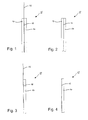
- Fig. 1 shows a first embodiment of an inventively configured electrode for an energy storage in section.
- the electrode 10 has an electrode carrier 12 to which an active electrode material 14 is applied on both sides.
- the active electrode material 14 is not applied to the electrode carrier 12 in the entire region, so that the electrode carrier 12 protrudes from the active electrode material 14 on at least one side.
- This protruding from the active electrode material 14 portion of the electrode carrier 12 can be used as a current collector 16 for supplying a charging current to the electrode 10 and discharging a discharge current from the electrode 10 so.
- Fig. 2 illustrated embodiment differs from the above first embodiment in that the active electrode material 14 is applied on both sides of the entire surface of the electrode carrier 12 so that it does not protrude from the active electrode material 14.
- a separate current conductor can be connected to the electrode carrier 12 in its extension (eg, welded).
- the third embodiment of the electrode which in Fig. 3 is different from the first embodiment described above in that the electrode carrier 12 is coated on one side only with the active electrode material 14.
- the fourth embodiment of Fig. 4 represents a combination of the above second and third embodiments. That is, the active electrode material 14 is applied only on one side of the electrode carrier 12 and the electrode carrier 12 is provided on one side substantially the entire surface with the active electrode material 14.
- the electrode carrier 12 is provided in all embodiments, for example in the form of a film, a tape, a plate, a sheet or the like and deposited electrolytically on rollers, for example, from a corresponding solution.
- the thickness of the electrode carrier 12 is, for example, in the range of about 4 microns to about 80 microns, more preferably in the range of about 5 microns to about 50 microns, more preferably in the range of about 5 microns to about 30 microns.
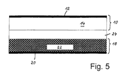
- FIG. 15 shows an example of an energy storage using an electrode 10 described above.
- the energy store for example a rechargeable secondary cell, a primary cell, a capacitor or the like, has a first electrode 10 (eg negative electrode or anode), a second electrode 18 (eg positive electrode or cathode) and a separator 24 between the two Electrodes 10, 18.
- a first electrode 10 eg negative electrode or anode
- a second electrode 18 eg positive electrode or cathode
- separator 24 between the two Electrodes 10, 18.
- the first electrode 10 for example, an electrode is used, as in Fig. 1 to 4 is shown.
- the second electrode 18 is basically constructed analogously to the first electrode 10, ie it also contains an electrode carrier 20 and an active electrode material 22 which is applied to the electrode carrier 20 on one or both sides.
- the separating element 24 between the two electrodes 10, 18 prevents direct, electrically conductive contact between the two electrodes 10, 18.
- the separating element 24 can be flush with the electrodes 10, 18 (in particular their active regions 14, 22), as in FIG Fig. 5 indicated. However, it can also be advantageous if the separating element 24 projects beyond the active electrode material 14, 22 of the directly adjacent electrode 10, 18 on at least one side.
- the energy store may include exactly one first electrode 10, a separator 24, and a second electrode 18, as in FIG Fig. 5 illustrated.
- the energy store contains a stack of a plurality of first electrodes 10 and a plurality of second electrodes 18, which are alternately stacked on top of each other and between each of which a separating element 24 is arranged.
- the energy storage can be based on Fig. 5 have explained construction or the stack structure either in a wound form or in a layered form.
- the material selection explained below can be used particularly advantageously for an anode 10 of a lithium-ion cell, without the present invention being restricted to this specific application.
- the electrode carrier 12 of the electrode 10 (see Fig. 1 to 4 ) for an energy store (see Fig. 5 ) is formed from an alloy which comprises at least predominantly copper and tin at a level of at least about 0.01% by weight.
- the alloy preferably comprises mixed crystals of copper and tin.
- the crystal lattice is predominantly formed by copper. Individual copper atoms are replaced by tin atoms, which occupy their lattice sites.
- the tin content of the electrode carrier is preferably in a range of 0.05 to 0.3 wt .-%, more preferably in a range of 0.1 to about 0.15 wt .-%.
- the copper material designated "PNA 216" of Prymetall GmbH & Co. KG, Germany may be used.
- This copper material has a tin content of at least 0.10 wt .-%.
- the specific electrical conductivity of this copper material is about 49 MS / m (in the soft state), its thermal conductivity about 350 W / m ⁇ K.
- the materials for the active electrode material 14 of the anode 10, for the electrode carrier 20 and the active electrode material 22 of the cathode 18 and for the separating element 24 there are no particular restrictions in the context of the present invention. Suitable materials for these components that can be used in the case of a lithium-ion cell, for example, in detail in the already mentioned DE 10 2005 042 916 A1 described, which is hereby incorporated by reference.
- the production of the electrodes 10, 18 and the energy storage in the invention is not limited to special methods.
- the above-described electrode of the invention is particularly suitable for large-sized energy stores (especially secondary lithium-ion cells) having a large capacity and high performance of over 3 or 5 Ah up to 300 Ah and more, which also has excellent long-term stability of, for example, over 3,000 charge / discharge Cycles and more and require security of supply.
- Energy storage with such an electrode can be used in an advantageous manner, for example in electric vehicles and electric hybrid vehicles.
Landscapes
- Engineering & Computer Science (AREA)
- Chemical & Material Sciences (AREA)
- Power Engineering (AREA)
- Materials Engineering (AREA)
- Microelectronics & Electronic Packaging (AREA)
- Chemical Kinetics & Catalysis (AREA)
- Electrochemistry (AREA)
- General Chemical & Material Sciences (AREA)
- Battery Electrode And Active Subsutance (AREA)
- Cell Electrode Carriers And Collectors (AREA)
- Electric Double-Layer Capacitors Or The Like (AREA)
Abstract
Description
- Die vorliegende Erfindung betrifft eine Elektrode für einen Energiespeicher und einen Energiespeicher mit einer solchen Elektrode. Die Erfindung wird im Zusammenhang mit Lithium-lonen-Akkumulatoren zum Antrieb von Elektrofahrzeugen oder elektrischen Hybridfahrzeugen beschrieben. Es wird darauf hingewiesen, dass die Erfindung auch auf Batterien mit abweichender Chemie bzw. unabhängig vom Einsatz der Batterie zur Versorgung des Antriebs eines Elektrofahrzeugs oder elektrischen Hybridfahrzeugs Anwendung finden kann.
- Energiespeicher werden vermehrt in Elektrofahrzeugen und elektrischen Hybridfahrzeugen eingesetzt, weshalb zunehmend Bedarf an Energiespeichern mit einer großen Kapazität, einer hohen Leistung und einer Langzeitstabilität besteht. Unter den Energiespeichern nehmen die Lithium(ionen)zellen insbesondere als Sekundärzellen aufgrund ihrer hohen spezifischen Energiespeicherdichte eine besondere Stellung ein.
- Ein Beispiel einer geschichteten Lithiumionenzelle ist in der
DE 10 2005 042 916 A1 offenbart und ein Beispiel einer gewickelten Lithiumionenzelle ist in derEP 0 949 699 B1 offenbart. Der hier als Lithiumionenzelle ausgebildete Energiespeicher enthält jeweils eine erste Elektrode, eine zweite Elektrode und ein Trennelement zwischen der ersten und der zweiten Elektrode bzw. eine abwechselnd übereinander gestapelte Anordnung dieser Komponenten. Wie zum Beispiel in derDE 10 2005 042 916 A1 genauer ausgeführt, sind die Elektroden dabei üblicherweise aus einem Elektrodenträger gebildet, auf den einseitig oder beidseitig ein aktives Elektrodenmaterial aufgebracht ist. Im Fall einer Lithiumionenzelle ist die Anode häufig aus einem Anodenträger aus Kupfer und einem aktiven Anodenmaterial zum Beispiel aus Graphit und die Kathode häufig aus einem Kathodenträger aus Aluminium und einem aktiven Kathodenmaterial aus lithierten Oxiden gebildet. - Der vorliegenden Erfindung liegt die Aufgabe zugrunde, einen Energiespeicher mit einer verbesserten Langzeitstabilität bzw. eine Elektrode für einen solchen Energiespeicher vorzusehen.
- Gemäß einem ersten Aspekt wird die Aufgabe durch eine Elektrode für einen Energiespeicher mit den Merkmalen des Anspruchs 1 gelöst. Vorteilhafte Ausgestaltungen und Weiterbildungen der Erfindung sind Gegenstand der abhängigen Ansprüche 2 bis 7. Ein Energiespeicher mit einer erfindungsgemäßen Elektrode ist in den Ansprüchen 8 bis 15 beschrieben.
- Die Elektrode für einen Energiespeicher enthält einen Elektrodenträger und ein aktives Elektrodenmaterial, das einseitig oder beidseitig auf den Elektrodenträger aufgebracht ist. Erfindungsgemäß ist vorgesehen, dass der Elektrodenträger aus einer Legierung mit einem Kupferanteil gebildet ist, wobei diese Legierung zusätzlich wenigstens Zinn mit einem Gehalt von wenigstens etwa 0,01 Gew.-% aufweist.
- Die vorgenannte Elektrode dient der Speicherung von Energie. Diese Elektrode speichert die Energie in chemischer Form. Zur Abgabe elektrischer Energie wird diese aus chemisch gespeicherte Energie umgewandelt. Je nach Ausbildung der Elektrode ist diese für nur einmalige Entladung oder auch zur Energieaufnahme geeignet. Während der Energieaufnahme, beispielsweise einem Ladevorgang, wird diese Energie in elektrischer Form zugeführt und in chemische Energie umgewandelt. Die Elektrode steht in wenigstens elektrischer Wirkverbindung mit einem Elektrolyten und einem Zuleiter.
- Der vorgenannte Energiespeicher dient der Versorgung eines Antriebs eines Elektrofahrzeugs oder eines elektrischen Hybrid Fahrzeugs. Dieser Energiespeicher kann aber auch andere Antriebe oder Verbraucher versorgen. Wenn der Energiespeicher nur zur einmaligen Abgabe elektrischer Energie dient, so spricht man von einer Primärzelle oder auch Batterie. Je nach Ausbildung kann dieser Energiespeicher auch elektrische Energie aufnehmen, beispielsweise durch Laden. In diesem Fall spricht man von einer Sekundärzelle oder einem Akkumulator. Innerhalb des Energiespeichers bzw. innerhalb dessen wenigstens einer galvanischen Zelle wird elektrische in chemische Energie umgewandelt und umgekehrt. An dieser Energiewandlung sind zwei Elektroden und ein Elektrolyt beteiligt. Mit jeder dieser Elektroden ist ein eigener Zuleiter elektrisch leitend verbunden. Diese Zuleiter sind wiederum mit einem Verbraucher elektrisch leitend verbunden, beispielsweise mit dem Antrieb eines Kraftfahrzeugs.
- Die vorgenannte Elektrode weist einen Elektrodenträger auf. Dieser Elektrodenträger ist ein elektrisch leitender Feststoff. Dieser Elektrodenträger weist vorzugsweise wenigstens ein Metall oder Graphit, erfindungsgemäß eine Legierung unter Beteiligung wenigstens von Kupfer und Zinn auf. Bevorzugt weist der Elektrodenträger wenigstens ein Kristallgitter auf, in der Praxis eine Vielzahl von Kristallgittern. Der Elektrodenträger leitet Elektronen aus diesem aktiven Elektrodenmaterial über den Zuleiter zum Verbraucher und auch in umgekehrter Richtung.
- Die vorgenannte Elektrode weist ferner aktives Elektrodenmaterial auf. Bei dem aktiven Elektrodenmaterial handelt es sich um ein Stoffgemisch, welches beispielsweise pastenartig beschaffen ist. Dieses aktive Elektrodenmaterial steht in Wirkverbindung mit dem Elektrolyten. Zwischen diesen beiden findet auch der Austausch von lonen statt. Das aktive Elektrodenmaterial ist einseitig oder beidseitig auf den Elektrodenträger aufgebracht und steht mit diesem in elektrischer Wirkverbindung. Elektronen werden durch Leitung zwischen Elektrodenträger und aktivem Elektrodenmaterial übertragen.
- Vorzugsweise ist der Elektrodenträger aus einer elektrisch leitenden Legierung gebildet. welche überwiegend Kupfer sowie Zinn mit einem Gehalt von wenigstens etwa 0,01 Gew.-% aufweist. Die erstarrte Legierung weist eine Vielzahl von Kristallgittern auf. Bei der Erstarrung flüssigen Kupfers bilden die einzelnen Kupferatome eine bevorzugte Kristallgitterform. Vorhandene Zinnatome ersetzen dabei einzelne Kupferatome in dessen Kristallgitter. Ein bestimmtes Volumen des Werkstoffs weist somit überwiegend Kupferatome und eine gewisse Anzahl Zinnatome als sogenannte Fremdatome aus.
- Bei der Versorgung eines elektrischen Antriebs eines Kraftfahrzeugs kann eine Tiefentladung nicht immer zuverlässig ausgeschlossen werden. Selbst bei gewissen Restladungen bzw. Restspannungen wird bereits Kupfer aus einem Elektrodenträger gelöst. Dieser Lösungsvorgang ist nicht völlig umkehrbar, der Elektrodenträger bzw. der Energiespeicher altert. Die Ausbildung eines Elektrodenträgers aus dieser Legierung hat zur Folge, dass im Vergleich zu anderen Kupferlegierungen bei geringer Restladung bzw. Restspannung weniger Kupfer unumkehrbar gelöst wird. Mit Verwendung der vorgeschlagenen Legierung für den Elektrodenträger wird die zugrundegelegte Aufgabe gelöst.
- Die wie oben beschrieben ausgebildete Elektrode ist daher insbesondere für großformatige Energiespeicher mit einer großen Kapazität und hoher Leistungsfähigkeit geeignet, wie sie zum Beispiel für Elektrofahrzeuge und elektrische Hybridfahrzeuge benötigt werden.
- Bevorzugt ist die Legierung für diesen Elektrodenträger so hergestellt, dass das enthaltene Kupfer den größten Gewichtsanteil dieser Legierung bildet.
- Bevorzugt weist die Legierung Mischkristalle aus Kupfer und Zinn auf. In diesen Mischkristallen ist eine gewisse Anzahl von Kupferatomen durch Zinnatome ersetzt. Ein Zinnatom weist im Vergleich zu einem Kupferatom einen geringfügig größeren Atomradius auf. Der größere Durchmesser der Zinnatome bzw. Fremdatome bewirkt eine Verzerrung des Gitters aus Kupferatomen. So wird auch eine mechanische Verfestigung des Werkstoffs bzw. des Elektrodenträgers erreicht. Weiterhin zeichnet sich diese Legierung durch hohe elektrische und thermische Leitfähigkeiten aus. Auch zeigt diese Legierung gute Korrosionsbeständigkeit und Beständigkeit gegen Spannungsrisskorrosion.
- Der Zinngehalt des Elektrodenträgers bzw. der Legierung liegt vorzugsweise in einem Bereich von 0,05 bis 0,3 Gew.-%, besonders bevorzugt in einem Bereich von 0,1 bis etwa 0,15 Gew.-%.
- Gemäß einem zweiten Aspekt wird die oben genannte Aufgabe durch einen Energiespeicher mit den Merkmalen des Anspruchs 7 gelöst. Vorteilhafte Ausgestaltungen und Weiterbildungen der Erfindung sind Gegenstand der abhängigen Ansprüche 8 bis 14.
- Der Energiespeicher enthält eine erste Elektrode (z.B. negative Elektrode, Anode), eine zweite Elektrode (z.B. positive Elektrode, Kathode) und ein Trennelement zwischen der ersten und der zweiten Elektrode, das einen direkten elektrischen Kontakt zwischen den beiden Elektroden verhindert. Die erste und/oder die zweite Elektrode sind dabei als eine Elektrode ausgebildet, wie sie oben beschrieben worden ist.
- Bei dem Energiespeicher kann es sich zum Beispiel um eine Sekundärzelle (d.h. wiederaufladbare galvanische Zelle), eine Primärzelle (d.h. nicht wiederaufladbare galvanische Zelle), einen Kondensator oder dergleichen handeln.
- Besonders bevorzugt ist der Einsatz der erfindungsgemäßen Elektrode in einer Lithium(ionen)zelle. Dabei weist der Energiespeicher wenigstens zwei Elektroden, ein Trennmittel, welches keine Elektronen leitet, und ferner einen Elektrolyten als lonenleiter auf. Der Elektrolyt ist dabei wenigstens teilweise im Trennmittel angeordnet. Bevorzugt weist wenigstens eine der Elektroden und/oder dieser Elektrolyt Lithium und/oder Lithium-lonen auf.
- In einer weiteren Ausgestaltung der Erfindung kann der Energiespeicher einen Stapel aus mehreren ersten Elektroden und mehreren zweiten Elektroden enthalten, die abwechselnd übereinander gestapelt sind und zwischen denen jeweils ein Trennelement angeordnet ist.
- Die vorliegende Erfindung ist in vorteilhafter Weise sowohl bei Energiespeichern anwendbar, bei denen die erste(n) und die zweite(n) Elektrode(n) geschichtet sind, als auch bei solchen, bei denen die erste(n) und die zweite(n) Elektrode(n) gewickelt sind.
- Obige sowie weitere Merkmale und Vorteile der Erfindung werden aus der nachfolgenden Beschreibung bevorzugter, nicht-einschränkender Ausführungsbeispiele unter Bezugnahme auf die beiliegenden Zeichnungen besser verständlich. Darin zeigen:
- Fig. 1
- eine schematische Schnittansicht einer Elektrode gemäß einem ersten Ausführungsbeispiel der Erfindung;
- Fig. 2
- eine schematische Schnittansicht einer Elektrode gemäß einem zweiten Ausführungsbeispiel der Erfindung;
- Fig. 3
- eine schematische Schnittansicht einer Elektrode gemäß einem dritten Ausführungsbeispiel der Erfindung;
- Fig. 4
- eine schematische Schnittansicht einer Elektrode gemäß einem vierten Ausführungsbeispiel der Erfindung;
- Fig. 5
- eine schematische Schnittansicht eines Energiespeichers mit einer Elektrode gemäß der Erfindung;
- Bezug nehmend auf
Fig. 1 bis 4 wird zunächst der Aufbau von verschiedenen Ausführungsbeispielen einer Elektrode für einen Energiespeicher näher erläutert. -
Fig. 1 zeigt ein erstes Ausführungsbeispiel einer erfindungsgemäß konfigurierten Elektrode für einen Energiespeicher im Schnitt. Die Elektrode 10 weist einen Elektrodenträger 12 auf, auf den beidseitig ein aktives Elektrodenmaterial 14 aufgebracht ist. In dem Ausführungsbeispiel vonFig. 1 ist das aktive Elektrodenmaterial 14 dabei nicht im gesamten Bereich auf den Elektrodenträger 12 aufgebracht, sodass der Elektrodenträger 12 auf wenigstens einer Seite aus dem aktiven Elektrodenmaterial 14 herausragt. Dieser aus dem aktiven Elektrodenmaterial 14 herausragende Teil des Elektrodenträgers 12 kann so als Stromableiter 16 zum Zuführen eines Ladestroms zur Elektrode 10 bzw. Abführen eines Entladestroms von der Elektrode 10 benutzt werden. - Das in
Fig. 2 veranschaulichte Ausführungsbeispiel unterscheidet sich von dem obigen ersten Ausführungsbeispiel darin, dass das aktive Elektrodenmaterial 14 beidseitig vollflächig auf den Elektrodenträger 12 aufgebracht ist, sodass dieser nicht aus dem aktiven Elektrodenmaterial 14 herausragt. In diesem Fall kann beim Aufbau eines Energiespeichers ggf. ein separater Stromableiter mit dem Elektrodenträger 12 in dessen Verlängerung verbunden (z.B. verschweißt) werden. - Das dritte Ausführungsbeispiel der Elektrode, das in
Fig. 3 dargestellt ist, unterscheidet sich von dem oben beschriebenen ersten Ausführungsbeispiel darin, dass der Elektrodenträger 12 nur einseitig mit dem aktiven Elektrodenmaterial 14 beschichtet ist. - Das vierte Ausführungsbeispiel von
Fig. 4 stellt eine Kombination der obigen zweiten und dritten Ausführungsbeispiele dar. D.h. das aktive Elektrodenmaterial 14 ist nur einseitig auf den Elektrodenträger 12 aufgebracht und der Elektrodenträger 12 ist auf der einen Seite im Wesentlichen vollflächig mit dem aktiven Elektrodenmaterial 14 versehen. - Der Elektrodenträger 12 wird in allen Ausführungsformen zum Beispiel in der Form einer Folie, eines Bandes, einer Platte, eines Bleches oder dergleichen bereitgestellt und beispielsweise aus einer entsprechenden Lösung elektrolytisch auf Walzen abgeschieden. Die Dicke des Elektrodenträgers 12 liegt zum Beispiel im Bereich von etwa 4 µm bis etwa 80 µm, bevorzugter im Bereich von etwa 5 µm bis etwa 50 µm, noch bevorzugter im Bereich von etwa 5 µm bis etwa 30 µm.
-
Fig. 5 zeigt ein Beispiel eines Energiespeichers, in dem eine oben beschriebene Elektrode 10 benutzt wird. - Der Energiespeicher, zum Beispiel eine wiederaufladbare Sekundärzelle, eine Primärzelle, ein Kondensator oder dergleichen, weist eine erste Elektrode 10 (z.B. negative Elektrode bzw. Anode), eine zweite Elektrode 18 (z.B. positive Elektrode bzw. Kathode) und ein Trennelement 24 zwischen den beiden Elektroden 10, 18 auf. Als erste Elektrode 10 wird beispielsweise eine Elektrode verwendet, wie sie in
Fig. 1 bis 4 dargestellt ist. Die zweite Elektrode 18 ist grundsätzlich analog zur ersten Elektrode 10 aufgebaut, d.h. sie enthält ebenfalls einen Elektrodenträger 20 und ein aktives Elektrodenmaterial 22, das einseitig oder beidseitig auf den Elektrodenträger 20 aufgebracht ist. - Das Trennelement 24 zwischen den beiden Elektroden 10, 18 verhindert einen direkten, elektrisch leitenden Kontakt zwischen den beiden Elektroden 10,18. Das Trennelement 24 kann bündig mit den Elektroden 10, 18 (insbesondere deren aktiven Bereichen 14, 22) abschließen, wie in
Fig. 5 angedeutet. Es kann aber auch vorteilhaft sein, wenn das Trennelement 24 auf zumindest einer Seite über das aktive Elektrodenmaterial 14, 22 der direkt benachbarten Elektrode 10, 18 hinausragt. - Der Energiespeicher kann zum Beispiel genau eine erste Elektrode 10, ein Trennelement 24 und eine zweite Elektrode 18 umfassen, wie in
Fig. 5 veranschaulicht. In vielen Anwendungsfällen ist es aber von Vorteil, wenn der Energiespeicher einen Stapel aus mehreren ersten Elektroden 10 und mehreren zweiten Elektroden 18, die abwechselnd übereinander gestapelt sind und zwischen denen jeweils ein Trennelement 24 angeordnet ist, enthält. - Außerdem kann der Energiespeicher den anhand von
Fig. 5 erläuterten Aufbau bzw. den Stapelaufbau entweder in einer gewickelten Form oder in einer geschichteten Form aufweisen. - Gemäß der Erfindung wird vorgeschlagen, für die erste und/oder die zweite Elektrode 10, 18 des Energiespeichers ein spezielles Material zu verwenden. Die nachfolgend erläuterte Materialauswahl ist dabei besonders vorteilhaft für eine Anode 10 einer Lithiumionenzelle einsetzbar, ohne dass die vorliegende Erfindung auf diese spezielle Anwendung beschränkt sein soll.
- Der Elektrodenträger 12 der Elektrode 10 (siehe
Fig. 1 bis 4 ) für einen Energiespeicher (sieheFig. 5 ) ist aus einer Legierung gebildet, welche wenigstens überwiegend Kupfer sowie Zinn mit einem Gehalt von wenigstens etwa 0,01 Gew.-% aufweist. - Bevorzugt weist die Legierung Mischkristalle aus Kupfer und Zinn auf. Dabei ist das Kristallgitter überwiegend von Kupfer gebildet. Einzelne Kupferatome sind durch Zinnatome ersetzt, welche deren Gitterplätze besetzen.
- Der Zinngehalt des Elektrodenträgers liegt vorzugsweise in einem Bereich von 0,05 bis 0,3 Gew.-%, besonders bevorzugt in einem Bereich von 0,1 bis etwa 0,15 Gew.-%.
- Als ein spezielles Beispiel für das Material des Elektrodenträgers 10 einer Elektrode 10 für einen Energiespeicher kann das Kupfermaterial mit der Bezeichnung "PNA 216" der Prymetall GmbH & Co. KG, Deutschland, verwendet werden. Dieses Kupfermaterial hat einen Zinngehalt von mindestens 0,10 Gew.-%. Die spezifische elektrische Leitfähigkeit dieses Kupfermaterials beträgt etwa 49 MS/m (im weichen Zustand), seine Wärmeleitfähigkeit etwa 350 W/m·K.
- Bezüglich der Materialien für das aktive Elektrodenmaterial 14 der Anode 10, für den Elektrodenträger 20 und das aktive Elektrodenmaterial 22 der Kathode 18 sowie für das Trennelement 24 bestehen im Rahmen der vorliegenden Erfindung keine besonderen Einschränkungen. Geeignete Materialien für diese Komponenten, die im Fall einer Lithiumionenzelle eingesetzt werden können, sind zum Beispiel ausführlich in der eingangs bereits genannten
DE 10 2005 042 916 A1 beschrieben, auf welche hiermit ausdrücklich Bezug genommen wird. Außerdem ist auch die Herstellung der Elektroden 10, 18 und der Energiespeicher im Rahmen der Erfindung nicht auf spezielle Verfahren beschränkt. - Die oben beschriebene Elektrode der Erfindung ist insbesondere für großformatige Energiespeicher (speziell sekundäre Lithiumionenzellen) mit einer großen Kapazität und einem hohen Leistungsvermögen von über 3 oder 5 Ah bis zu 300 Ah und mehr, die zudem eine ausgezeichnete Langzeitstabilität von zum Beispiel über 3.000 Lade/Entlade-Zyklen und mehr und Versorgungssicherheit erfordern. Energiespeicher mit einer solchen Elektrode können dabei in vorteilhafter Weise zum Beispiel in Elektrofahrzeugen und elektrischen Hybridfahrzeugen eingesetzt werden.
Claims (15)
- Elektrode (10) für einen Energiespeicher, mit
einem Elektrodenträger (12);
und einem aktiven Elektrodenmaterial (14), welches einseitig oder beidseitig auf den Elektrodenträger (12) aufgebracht ist,
dadurch gekennzeichnet, dass
der Elektrodenträger (12) aus einer Legierung mit einem Kupferanteil gebildet ist, wobei diese Legierung zusätzlich wenigstens Zinn mit einem Gehalt von wenigstens etwa 0,01 Gew.-% aufweist. - Elektrode nach Anspruch 1,
dadurch gekennzeichnet, dass
der Kupferanteil den größten Gewichtsanteil der Legierung bildet. - Elektrode nach einem der vorhergehenden Ansprüche,
dadurch gekennzeichnet, dass
die Legierung Mischkristalle unter Beteiligung von Kupfer und Zinn aufweist. - Elektrode nach einem der vorhergehenden Ansprüche,
dadurch gekennzeichnet, dass
die Legierung des Elektrodenträgers (12) mindestens etwa 0,05 Gew.-% Zinn aufweist. - Elektrode nach einem der vorhergehenden Ansprüche,
dadurch gekennzeichnet, dass
das Legierung des Elektrodenträgers (12) mindestens etwa 0,1 Gew.-% Zinn aufweist. - Elektrode nach einem der vorhergehenden Ansprüche,
dadurch gekennzeichnet, dass
die Legierung des Elektrodenträgers (12) höchstens etwa 0,3 Gew.-% Zinn aufweist. - Elektrode nach einem der Ansprüche 1 bis 5,
dadurch gekennzeichnet, dass
die Legierung des Elektrodenträgers (12) höchstens etwa 0,15 Gew.-% Zinn aufweist. - Energiespeicher, mit
einer ersten Elektrode (10);
einer zweiten Elektrode (18); und
einem Trennelement (24) zwischen der ersten und der zweiten Elektrode,
dadurch gekennzeichnet, dass
die erste und/oder die zweite Elektrode (10, 18) als eine Elektrode nach einem der Ansprüche 1 bis 7 ausgebildet ist. - Energiespeicher nach Anspruch 8,
dadurch gekennzeichnet, dass
der Energiespeicher eine Sekundärzelle ist. - Energiespeicher nach Anspruch 8,
dadurch gekennzeichnet, dass
der Energiespeicher eine Primärzelle ist. - Energiespeicher nach Anspruch 8
dadurch gekennzeichnet, dass
der Energiespeicher ein Kondensator ist. - Energiespeicher nach einem der Ansprüche 9 bis 11.
dadurch gekennzeichnet, dass
der Energiespeicher ferner einen Elektrolyten aufweist, wobei wenigstens eine Elektrode und/oder dieser Elektrolyt Lithium und/oder Lithium-lonen umfasst. - Energiespeicher nach einem der Ansprüche 8 bis 12,
dadurch gekennzeichnet, dass
der Energiespeicher einen Stapel aus mehreren ersten Elektroden (10) und mehreren zweiten Elektroden (18) enthält, die abwechselnd übereinander gestapelt sind und zwischen denen jeweils ein Trennelement (24) angeordnet ist. - Energiespeicher nach einem der Ansprüche 8 bis 13,
dadurch gekennzeichnet, dass
die erste(n) und zweite(n) Elektrode(n) (10, 18) geschichtet sind. - Energiespeicher nach einem der Ansprüche 8 bis 13,
dadurch gekennzeichnet, dass
die erste(n) und zweite(n) Elektrode(n) (10, 18) gewickelt sind.
Applications Claiming Priority (1)
| Application Number | Priority Date | Filing Date | Title |
|---|---|---|---|
| DE102008031537A DE102008031537A1 (de) | 2008-07-03 | 2008-07-03 | Elektrode für einen Energiespeicher |
Publications (2)
| Publication Number | Publication Date |
|---|---|
| EP2141760A1 true EP2141760A1 (de) | 2010-01-06 |
| EP2141760B1 EP2141760B1 (de) | 2013-11-20 |
Family
ID=41055488
Family Applications (1)
| Application Number | Title | Priority Date | Filing Date |
|---|---|---|---|
| EP09008770.1A Not-in-force EP2141760B1 (de) | 2008-07-03 | 2009-07-03 | Elektrode für einen Energiespeicher |
Country Status (3)
| Country | Link |
|---|---|
| US (1) | US20100021813A1 (de) |
| EP (1) | EP2141760B1 (de) |
| DE (1) | DE102008031537A1 (de) |
Cited By (2)
| Publication number | Priority date | Publication date | Assignee | Title |
|---|---|---|---|---|
| DE102011120439A1 (de) | 2011-12-07 | 2013-06-13 | Daimler Ag | Stromversorgungsvorrichtung und Verfahren zum Steuern des Betriebs einer solchen |
| US11398356B2 (en) | 2016-05-19 | 2022-07-26 | Battarix Enterprises, Llc | Primary cells for high discharge rate |
Families Citing this family (1)
| Publication number | Priority date | Publication date | Assignee | Title |
|---|---|---|---|---|
| PL2418246T3 (pl) * | 2009-04-08 | 2015-03-31 | Techno Polymer Co Ltd | Element wyposażenia wewnętrznego pojazdu charakteryzujący się zmniejszonymi odgłosami skrzypienia |
Citations (7)
| Publication number | Priority date | Publication date | Assignee | Title |
|---|---|---|---|---|
| JPS643959A (en) * | 1987-06-26 | 1989-01-09 | Shin Kobe Electric Machinery | Lead-antimony alloy current collector |
| EP0949699B1 (de) | 1998-03-18 | 2005-06-01 | Ngk Insulators, Ltd. | Elektrische Verbindungsanordnung in einer Lithium- Sekundärbatterie |
| US20050214639A1 (en) * | 2004-03-26 | 2005-09-29 | Kari Terho | Electrical contact element for alkaline cells |
| DE102005042916A1 (de) | 2005-09-08 | 2007-03-22 | Degussa Ag | Stapel aus abwechselnd übereinander gestapelten und fixierten Separatoren und Elektroden für Li-Akkumulatoren |
| US20070077494A1 (en) * | 2005-09-29 | 2007-04-05 | Sanyo Electric Co., Ltd. | Lithium secondary battery |
| US20080100990A1 (en) * | 2006-10-26 | 2008-05-01 | Buiel Edward R | Cell Assemby for an Energy Storage Device Using PTFE Binder in Activated Carbon Electrodes |
| US20080102359A1 (en) * | 2006-10-26 | 2008-05-01 | Matsushita Electric Industrial Co., Ltd. | Electrode plate for battery and lithium secondary battery including the same |
Family Cites Families (1)
| Publication number | Priority date | Publication date | Assignee | Title |
|---|---|---|---|---|
| JP4026356B2 (ja) * | 2001-11-07 | 2007-12-26 | 松下電器産業株式会社 | 負極集電体およびこの集電体を用いた負極板と非水電解液二次電池 |
-
2008
- 2008-07-03 DE DE102008031537A patent/DE102008031537A1/de not_active Withdrawn
-
2009
- 2009-07-02 US US12/497,077 patent/US20100021813A1/en not_active Abandoned
- 2009-07-03 EP EP09008770.1A patent/EP2141760B1/de not_active Not-in-force
Patent Citations (7)
| Publication number | Priority date | Publication date | Assignee | Title |
|---|---|---|---|---|
| JPS643959A (en) * | 1987-06-26 | 1989-01-09 | Shin Kobe Electric Machinery | Lead-antimony alloy current collector |
| EP0949699B1 (de) | 1998-03-18 | 2005-06-01 | Ngk Insulators, Ltd. | Elektrische Verbindungsanordnung in einer Lithium- Sekundärbatterie |
| US20050214639A1 (en) * | 2004-03-26 | 2005-09-29 | Kari Terho | Electrical contact element for alkaline cells |
| DE102005042916A1 (de) | 2005-09-08 | 2007-03-22 | Degussa Ag | Stapel aus abwechselnd übereinander gestapelten und fixierten Separatoren und Elektroden für Li-Akkumulatoren |
| US20070077494A1 (en) * | 2005-09-29 | 2007-04-05 | Sanyo Electric Co., Ltd. | Lithium secondary battery |
| US20080100990A1 (en) * | 2006-10-26 | 2008-05-01 | Buiel Edward R | Cell Assemby for an Energy Storage Device Using PTFE Binder in Activated Carbon Electrodes |
| US20080102359A1 (en) * | 2006-10-26 | 2008-05-01 | Matsushita Electric Industrial Co., Ltd. | Electrode plate for battery and lithium secondary battery including the same |
Cited By (5)
| Publication number | Priority date | Publication date | Assignee | Title |
|---|---|---|---|---|
| DE102011120439A1 (de) | 2011-12-07 | 2013-06-13 | Daimler Ag | Stromversorgungsvorrichtung und Verfahren zum Steuern des Betriebs einer solchen |
| US11398356B2 (en) | 2016-05-19 | 2022-07-26 | Battarix Enterprises, Llc | Primary cells for high discharge rate |
| US11670463B2 (en) | 2016-05-19 | 2023-06-06 | Battarix Enterprises, Llc | Primary cells for high discharge rate |
| US12002621B2 (en) | 2016-05-19 | 2024-06-04 | Battarix Enterprises, Llc | Electrochemical cells for high discharge |
| US12300432B2 (en) | 2016-05-19 | 2025-05-13 | Battarix Enterprises, Llc | Electrochemical cells for high discharge |
Also Published As
| Publication number | Publication date |
|---|---|
| US20100021813A1 (en) | 2010-01-28 |
| DE102008031537A1 (de) | 2010-01-07 |
| EP2141760B1 (de) | 2013-11-20 |
Similar Documents
| Publication | Publication Date | Title |
|---|---|---|
| DE69908803T2 (de) | Verbundelektrode mit ptc polymer | |
| DE69707622T2 (de) | Aufladbare lithiumbatterie mit umkehrbarer kapazität | |
| DE69925532T2 (de) | Elektrische Verbindungsanordnung in einer Lithium- Sekundärbatterie | |
| DE102012204613A1 (de) | Negative Flüssigmetallelektrode für Lithiumionenbatterien | |
| DE112012002904T5 (de) | Aktives Material für eine wiederaufladbare Batterie | |
| EP2845251B1 (de) | Texturierte stromableiterfolie | |
| DE112019002209T5 (de) | Elektrodenkonfiguration mit einem Protrusioninhibitions-Trennelement | |
| DE102012224324B4 (de) | Batteriezelle, Elektrodenmaterialschichtstapel und Verwendung eines Elektrodenmaterialschichtstapel in einer Batteriezelle | |
| EP3120400B1 (de) | Elektrode für eine lithium-zelle | |
| EP2141760B1 (de) | Elektrode für einen Energiespeicher | |
| EP2514009B1 (de) | Galvanischen elements | |
| DE19654057C2 (de) | Verfahren zur Verbesserung der Leistungsdichte von Lithium-Sekundärbatterien | |
| DE102010062873A1 (de) | Lithium-Ionen-Zelle, Lithium-Ionen-Akkumulator sowie Kraftfahrzeug mit einem Lithium-Ionen-Akkumulator | |
| DE102018221904A1 (de) | Elektrodeneinheit für eine Batteriezelle, Batteriezelle und Verfahren zur Herstellung einer Elektrodeneinheit | |
| DE102011075202B4 (de) | Schichtanordnung | |
| EP2866285B1 (de) | Lithium-Ionen-Batterien und Verfahren zu ihrer Herstellung | |
| WO2009089823A1 (de) | Energiespeicher und bordnetz mit einem solchen energiespeicher | |
| EP3553867A1 (de) | Verfahren zur herstellung eines schichtaufbaus für einen lithium-ionen-festkörperakkumulator | |
| EP3216073B1 (de) | Elektrode für eine batteriezelle und batteriezelle | |
| EP3113275B1 (de) | Sekundäre magnesiumbatterie und elektrolytsystem sowie elektrode für eine sekundäre magnesiumbatterie | |
| DE102010062852A1 (de) | Ableiterfolie für eine Lithium-Ionen-Zelle, Lithium-Ionen-Akkumulator sowie Kraftfahrzeug mit einem Lithium-Ionen-Akkumulator | |
| DE202009013174U1 (de) | Elektrode für einen Energiespeicher | |
| DE102020111242A1 (de) | Lithiumionenbatterie | |
| DE102021127929A1 (de) | Kathode sowie eine Lithiumionen-Festkörperbatterie mit der Kathode | |
| EP2218126A1 (de) | Elektrode für einen energiespeicher |
Legal Events
| Date | Code | Title | Description |
|---|---|---|---|
| PUAI | Public reference made under article 153(3) epc to a published international application that has entered the european phase |
Free format text: ORIGINAL CODE: 0009012 |
|
| AK | Designated contracting states |
Kind code of ref document: A1 Designated state(s): AT BE BG CH CY CZ DE DK EE ES FI FR GB GR HR HU IE IS IT LI LT LU LV MC MK MT NL NO PL PT RO SE SI SK SM TR |
|
| 17P | Request for examination filed |
Effective date: 20100512 |
|
| 17Q | First examination report despatched |
Effective date: 20101112 |
|
| RIN1 | Information on inventor provided before grant (corrected) |
Inventor name: SCHAEFER, TIM Inventor name: GUTSCH, ANDREAS, DR. |
|
| RIC1 | Information provided on ipc code assigned before grant |
Ipc: H01G 11/22 20130101ALI20130412BHEP Ipc: H01M 4/66 20060101AFI20130412BHEP Ipc: H01M 10/052 20100101ALN20130412BHEP Ipc: H01G 9/04 20060101ALI20130412BHEP |
|
| GRAP | Despatch of communication of intention to grant a patent |
Free format text: ORIGINAL CODE: EPIDOSNIGR1 |
|
| INTG | Intention to grant announced |
Effective date: 20130528 |
|
| GRAS | Grant fee paid |
Free format text: ORIGINAL CODE: EPIDOSNIGR3 |
|
| GRAA | (expected) grant |
Free format text: ORIGINAL CODE: 0009210 |
|
| AK | Designated contracting states |
Kind code of ref document: B1 Designated state(s): AT BE BG CH CY CZ DE DK EE ES FI FR GB GR HR HU IE IS IT LI LT LU LV MC MK MT NL NO PL PT RO SE SI SK SM TR |
|
| REG | Reference to a national code |
Ref country code: GB Ref legal event code: FG4D Free format text: NOT ENGLISH |
|
| REG | Reference to a national code |
Ref country code: CH Ref legal event code: EP |
|
| REG | Reference to a national code |
Ref country code: AT Ref legal event code: REF Ref document number: 642098 Country of ref document: AT Kind code of ref document: T Effective date: 20131215 |
|
| REG | Reference to a national code |
Ref country code: IE Ref legal event code: FG4D Free format text: LANGUAGE OF EP DOCUMENT: GERMAN |
|
| REG | Reference to a national code |
Ref country code: DE Ref legal event code: R096 Ref document number: 502009008361 Country of ref document: DE Effective date: 20140116 |
|
| REG | Reference to a national code |
Ref country code: NL Ref legal event code: VDEP Effective date: 20131120 |
|
| REG | Reference to a national code |
Ref country code: LT Ref legal event code: MG4D |
|
| PG25 | Lapsed in a contracting state [announced via postgrant information from national office to epo] |
Ref country code: HR Free format text: LAPSE BECAUSE OF FAILURE TO SUBMIT A TRANSLATION OF THE DESCRIPTION OR TO PAY THE FEE WITHIN THE PRESCRIBED TIME-LIMIT Effective date: 20131120 Ref country code: NL Free format text: LAPSE BECAUSE OF FAILURE TO SUBMIT A TRANSLATION OF THE DESCRIPTION OR TO PAY THE FEE WITHIN THE PRESCRIBED TIME-LIMIT Effective date: 20131120 Ref country code: FI Free format text: LAPSE BECAUSE OF FAILURE TO SUBMIT A TRANSLATION OF THE DESCRIPTION OR TO PAY THE FEE WITHIN THE PRESCRIBED TIME-LIMIT Effective date: 20131120 Ref country code: LT Free format text: LAPSE BECAUSE OF FAILURE TO SUBMIT A TRANSLATION OF THE DESCRIPTION OR TO PAY THE FEE WITHIN THE PRESCRIBED TIME-LIMIT Effective date: 20131120 Ref country code: IS Free format text: LAPSE BECAUSE OF FAILURE TO SUBMIT A TRANSLATION OF THE DESCRIPTION OR TO PAY THE FEE WITHIN THE PRESCRIBED TIME-LIMIT Effective date: 20140320 Ref country code: NO Free format text: LAPSE BECAUSE OF FAILURE TO SUBMIT A TRANSLATION OF THE DESCRIPTION OR TO PAY THE FEE WITHIN THE PRESCRIBED TIME-LIMIT Effective date: 20140220 Ref country code: SE Free format text: LAPSE BECAUSE OF FAILURE TO SUBMIT A TRANSLATION OF THE DESCRIPTION OR TO PAY THE FEE WITHIN THE PRESCRIBED TIME-LIMIT Effective date: 20131120 |
|
| PG25 | Lapsed in a contracting state [announced via postgrant information from national office to epo] |
Ref country code: LV Free format text: LAPSE BECAUSE OF FAILURE TO SUBMIT A TRANSLATION OF THE DESCRIPTION OR TO PAY THE FEE WITHIN THE PRESCRIBED TIME-LIMIT Effective date: 20131120 Ref country code: ES Free format text: LAPSE BECAUSE OF FAILURE TO SUBMIT A TRANSLATION OF THE DESCRIPTION OR TO PAY THE FEE WITHIN THE PRESCRIBED TIME-LIMIT Effective date: 20131120 |
|
| PG25 | Lapsed in a contracting state [announced via postgrant information from national office to epo] |
Ref country code: PT Free format text: LAPSE BECAUSE OF FAILURE TO SUBMIT A TRANSLATION OF THE DESCRIPTION OR TO PAY THE FEE WITHIN THE PRESCRIBED TIME-LIMIT Effective date: 20140320 |
|
| PG25 | Lapsed in a contracting state [announced via postgrant information from national office to epo] |
Ref country code: EE Free format text: LAPSE BECAUSE OF FAILURE TO SUBMIT A TRANSLATION OF THE DESCRIPTION OR TO PAY THE FEE WITHIN THE PRESCRIBED TIME-LIMIT Effective date: 20131120 |
|
| REG | Reference to a national code |
Ref country code: DE Ref legal event code: R097 Ref document number: 502009008361 Country of ref document: DE |
|
| PG25 | Lapsed in a contracting state [announced via postgrant information from national office to epo] |
Ref country code: RO Free format text: LAPSE BECAUSE OF FAILURE TO SUBMIT A TRANSLATION OF THE DESCRIPTION OR TO PAY THE FEE WITHIN THE PRESCRIBED TIME-LIMIT Effective date: 20131120 Ref country code: CZ Free format text: LAPSE BECAUSE OF FAILURE TO SUBMIT A TRANSLATION OF THE DESCRIPTION OR TO PAY THE FEE WITHIN THE PRESCRIBED TIME-LIMIT Effective date: 20131120 Ref country code: PL Free format text: LAPSE BECAUSE OF FAILURE TO SUBMIT A TRANSLATION OF THE DESCRIPTION OR TO PAY THE FEE WITHIN THE PRESCRIBED TIME-LIMIT Effective date: 20131120 Ref country code: SK Free format text: LAPSE BECAUSE OF FAILURE TO SUBMIT A TRANSLATION OF THE DESCRIPTION OR TO PAY THE FEE WITHIN THE PRESCRIBED TIME-LIMIT Effective date: 20131120 |
|
| PLBE | No opposition filed within time limit |
Free format text: ORIGINAL CODE: 0009261 |
|
| STAA | Information on the status of an ep patent application or granted ep patent |
Free format text: STATUS: NO OPPOSITION FILED WITHIN TIME LIMIT |
|
| PG25 | Lapsed in a contracting state [announced via postgrant information from national office to epo] |
Ref country code: DK Free format text: LAPSE BECAUSE OF FAILURE TO SUBMIT A TRANSLATION OF THE DESCRIPTION OR TO PAY THE FEE WITHIN THE PRESCRIBED TIME-LIMIT Effective date: 20131120 |
|
| 26N | No opposition filed |
Effective date: 20140821 |
|
| REG | Reference to a national code |
Ref country code: DE Ref legal event code: R097 Ref document number: 502009008361 Country of ref document: DE Effective date: 20140821 |
|
| PG25 | Lapsed in a contracting state [announced via postgrant information from national office to epo] |
Ref country code: SI Free format text: LAPSE BECAUSE OF FAILURE TO SUBMIT A TRANSLATION OF THE DESCRIPTION OR TO PAY THE FEE WITHIN THE PRESCRIBED TIME-LIMIT Effective date: 20131120 Ref country code: LU Free format text: LAPSE BECAUSE OF FAILURE TO SUBMIT A TRANSLATION OF THE DESCRIPTION OR TO PAY THE FEE WITHIN THE PRESCRIBED TIME-LIMIT Effective date: 20140703 |
|
| REG | Reference to a national code |
Ref country code: CH Ref legal event code: PL Ref country code: DE Ref legal event code: R082 Ref document number: 502009008361 Country of ref document: DE |
|
| GBPC | Gb: european patent ceased through non-payment of renewal fee |
Effective date: 20140703 |
|
| REG | Reference to a national code |
Ref country code: IE Ref legal event code: MM4A |
|
| REG | Reference to a national code |
Ref country code: FR Ref legal event code: ST Effective date: 20150331 |
|
| PG25 | Lapsed in a contracting state [announced via postgrant information from national office to epo] |
Ref country code: CH Free format text: LAPSE BECAUSE OF NON-PAYMENT OF DUE FEES Effective date: 20140731 Ref country code: LI Free format text: LAPSE BECAUSE OF NON-PAYMENT OF DUE FEES Effective date: 20140731 Ref country code: IT Free format text: LAPSE BECAUSE OF FAILURE TO SUBMIT A TRANSLATION OF THE DESCRIPTION OR TO PAY THE FEE WITHIN THE PRESCRIBED TIME-LIMIT Effective date: 20131120 |
|
| PG25 | Lapsed in a contracting state [announced via postgrant information from national office to epo] |
Ref country code: GB Free format text: LAPSE BECAUSE OF NON-PAYMENT OF DUE FEES Effective date: 20140703 Ref country code: FR Free format text: LAPSE BECAUSE OF NON-PAYMENT OF DUE FEES Effective date: 20140731 |
|
| PG25 | Lapsed in a contracting state [announced via postgrant information from national office to epo] |
Ref country code: IE Free format text: LAPSE BECAUSE OF NON-PAYMENT OF DUE FEES Effective date: 20140703 |
|
| REG | Reference to a national code |
Ref country code: AT Ref legal event code: MM01 Ref document number: 642098 Country of ref document: AT Kind code of ref document: T Effective date: 20140703 |
|
| PG25 | Lapsed in a contracting state [announced via postgrant information from national office to epo] |
Ref country code: AT Free format text: LAPSE BECAUSE OF NON-PAYMENT OF DUE FEES Effective date: 20140703 |
|
| PGFP | Annual fee paid to national office [announced via postgrant information from national office to epo] |
Ref country code: DE Payment date: 20150930 Year of fee payment: 7 |
|
| PG25 | Lapsed in a contracting state [announced via postgrant information from national office to epo] |
Ref country code: SM Free format text: LAPSE BECAUSE OF FAILURE TO SUBMIT A TRANSLATION OF THE DESCRIPTION OR TO PAY THE FEE WITHIN THE PRESCRIBED TIME-LIMIT Effective date: 20131120 Ref country code: MC Free format text: LAPSE BECAUSE OF FAILURE TO SUBMIT A TRANSLATION OF THE DESCRIPTION OR TO PAY THE FEE WITHIN THE PRESCRIBED TIME-LIMIT Effective date: 20131120 |
|
| PG25 | Lapsed in a contracting state [announced via postgrant information from national office to epo] |
Ref country code: CY Free format text: LAPSE BECAUSE OF FAILURE TO SUBMIT A TRANSLATION OF THE DESCRIPTION OR TO PAY THE FEE WITHIN THE PRESCRIBED TIME-LIMIT Effective date: 20131120 Ref country code: GR Free format text: LAPSE BECAUSE OF FAILURE TO SUBMIT A TRANSLATION OF THE DESCRIPTION OR TO PAY THE FEE WITHIN THE PRESCRIBED TIME-LIMIT Effective date: 20140221 Ref country code: MT Free format text: LAPSE BECAUSE OF FAILURE TO SUBMIT A TRANSLATION OF THE DESCRIPTION OR TO PAY THE FEE WITHIN THE PRESCRIBED TIME-LIMIT Effective date: 20131120 Ref country code: BG Free format text: LAPSE BECAUSE OF FAILURE TO SUBMIT A TRANSLATION OF THE DESCRIPTION OR TO PAY THE FEE WITHIN THE PRESCRIBED TIME-LIMIT Effective date: 20131120 |
|
| PG25 | Lapsed in a contracting state [announced via postgrant information from national office to epo] |
Ref country code: HU Free format text: LAPSE BECAUSE OF FAILURE TO SUBMIT A TRANSLATION OF THE DESCRIPTION OR TO PAY THE FEE WITHIN THE PRESCRIBED TIME-LIMIT; INVALID AB INITIO Effective date: 20090703 Ref country code: TR Free format text: LAPSE BECAUSE OF FAILURE TO SUBMIT A TRANSLATION OF THE DESCRIPTION OR TO PAY THE FEE WITHIN THE PRESCRIBED TIME-LIMIT Effective date: 20131120 Ref country code: BE Free format text: LAPSE BECAUSE OF FAILURE TO SUBMIT A TRANSLATION OF THE DESCRIPTION OR TO PAY THE FEE WITHIN THE PRESCRIBED TIME-LIMIT Effective date: 20140731 |
|
| REG | Reference to a national code |
Ref country code: DE Ref legal event code: R119 Ref document number: 502009008361 Country of ref document: DE |
|
| PG25 | Lapsed in a contracting state [announced via postgrant information from national office to epo] |
Ref country code: DE Free format text: LAPSE BECAUSE OF NON-PAYMENT OF DUE FEES Effective date: 20170201 |
|
| PG25 | Lapsed in a contracting state [announced via postgrant information from national office to epo] |
Ref country code: MK Free format text: LAPSE BECAUSE OF FAILURE TO SUBMIT A TRANSLATION OF THE DESCRIPTION OR TO PAY THE FEE WITHIN THE PRESCRIBED TIME-LIMIT Effective date: 20131120 |