EP0949699B1 - Electrical connection structure in a lithium secondary battery - Google Patents
Electrical connection structure in a lithium secondary battery Download PDFInfo
- Publication number
- EP0949699B1 EP0949699B1 EP99105468A EP99105468A EP0949699B1 EP 0949699 B1 EP0949699 B1 EP 0949699B1 EP 99105468 A EP99105468 A EP 99105468A EP 99105468 A EP99105468 A EP 99105468A EP 0949699 B1 EP0949699 B1 EP 0949699B1
- Authority
- EP
- European Patent Office
- Prior art keywords
- tabs
- positive
- negative
- lithium secondary
- secondary battery
- Prior art date
- Legal status (The legal status is an assumption and is not a legal conclusion. Google has not performed a legal analysis and makes no representation as to the accuracy of the status listed.)
- Expired - Lifetime
Links
- 229910052744 lithium Inorganic materials 0.000 title claims description 27
- WHXSMMKQMYFTQS-UHFFFAOYSA-N Lithium Chemical compound [Li] WHXSMMKQMYFTQS-UHFFFAOYSA-N 0.000 title claims description 26
- 238000002788 crimping Methods 0.000 claims description 29
- 238000003466 welding Methods 0.000 claims description 21
- 230000005611 electricity Effects 0.000 claims description 11
- 229920000642 polymer Polymers 0.000 claims description 3
- 238000000034 method Methods 0.000 description 24
- 239000006185 dispersion Substances 0.000 description 18
- 239000011888 foil Substances 0.000 description 18
- 230000000052 comparative effect Effects 0.000 description 15
- RYGMFSIKBFXOCR-UHFFFAOYSA-N Copper Chemical compound [Cu] RYGMFSIKBFXOCR-UHFFFAOYSA-N 0.000 description 14
- 229910052782 aluminium Inorganic materials 0.000 description 13
- XAGFODPZIPBFFR-UHFFFAOYSA-N aluminium Chemical compound [Al] XAGFODPZIPBFFR-UHFFFAOYSA-N 0.000 description 13
- 229910052751 metal Inorganic materials 0.000 description 12
- 239000002184 metal Substances 0.000 description 12
- 239000000463 material Substances 0.000 description 10
- 239000011889 copper foil Substances 0.000 description 9
- -1 lithium transition metal compound Chemical class 0.000 description 9
- 238000004804 winding Methods 0.000 description 8
- OKTJSMMVPCPJKN-UHFFFAOYSA-N Carbon Chemical compound [C] OKTJSMMVPCPJKN-UHFFFAOYSA-N 0.000 description 6
- 230000000694 effects Effects 0.000 description 6
- 229910052802 copper Inorganic materials 0.000 description 5
- 239000010949 copper Substances 0.000 description 5
- 239000004698 Polyethylene Substances 0.000 description 4
- 230000006866 deterioration Effects 0.000 description 4
- 239000007772 electrode material Substances 0.000 description 4
- 229920000573 polyethylene Polymers 0.000 description 4
- 239000007774 positive electrode material Substances 0.000 description 4
- HBBGRARXTFLTSG-UHFFFAOYSA-N Lithium ion Chemical compound [Li+] HBBGRARXTFLTSG-UHFFFAOYSA-N 0.000 description 3
- 239000004743 Polypropylene Substances 0.000 description 3
- 229910001416 lithium ion Inorganic materials 0.000 description 3
- 229920001155 polypropylene Polymers 0.000 description 3
- CURLTUGMZLYLDI-UHFFFAOYSA-N Carbon dioxide Chemical compound O=C=O CURLTUGMZLYLDI-UHFFFAOYSA-N 0.000 description 2
- KMTRUDSVKNLOMY-UHFFFAOYSA-N Ethylene carbonate Chemical compound O=C1OCCO1 KMTRUDSVKNLOMY-UHFFFAOYSA-N 0.000 description 2
- PXHVJJICTQNCMI-UHFFFAOYSA-N Nickel Chemical compound [Ni] PXHVJJICTQNCMI-UHFFFAOYSA-N 0.000 description 2
- 239000006230 acetylene black Substances 0.000 description 2
- 239000011230 binding agent Substances 0.000 description 2
- 238000007599 discharging Methods 0.000 description 2
- 239000003792 electrolyte Substances 0.000 description 2
- 230000010220 ion permeability Effects 0.000 description 2
- 229910000625 lithium cobalt oxide Inorganic materials 0.000 description 2
- BFZPBUKRYWOWDV-UHFFFAOYSA-N lithium;oxido(oxo)cobalt Chemical compound [Li+].[O-][Co]=O BFZPBUKRYWOWDV-UHFFFAOYSA-N 0.000 description 2
- 239000007769 metal material Substances 0.000 description 2
- 229920006254 polymer film Polymers 0.000 description 2
- 239000004065 semiconductor Substances 0.000 description 2
- 239000002904 solvent Substances 0.000 description 2
- BVKZGUZCCUSVTD-UHFFFAOYSA-L Carbonate Chemical compound [O-]C([O-])=O BVKZGUZCCUSVTD-UHFFFAOYSA-L 0.000 description 1
- 229910001290 LiPF6 Inorganic materials 0.000 description 1
- 230000001133 acceleration Effects 0.000 description 1
- PNEYBMLMFCGWSK-UHFFFAOYSA-N aluminium oxide Inorganic materials [O-2].[O-2].[O-2].[Al+3].[Al+3] PNEYBMLMFCGWSK-UHFFFAOYSA-N 0.000 description 1
- 239000002194 amorphous carbon material Substances 0.000 description 1
- 229910002092 carbon dioxide Inorganic materials 0.000 description 1
- 239000001569 carbon dioxide Substances 0.000 description 1
- 238000000605 extraction Methods 0.000 description 1
- 239000002803 fossil fuel Substances 0.000 description 1
- 229910021385 hard carbon Inorganic materials 0.000 description 1
- 238000009413 insulation Methods 0.000 description 1
- 229910002102 lithium manganese oxide Inorganic materials 0.000 description 1
- CJYZTOPVWURGAI-UHFFFAOYSA-N lithium;manganese;manganese(3+);oxygen(2-) Chemical compound [Li+].[O-2].[O-2].[O-2].[O-2].[Mn].[Mn+3] CJYZTOPVWURGAI-UHFFFAOYSA-N 0.000 description 1
- VROAXDSNYPAOBJ-UHFFFAOYSA-N lithium;oxido(oxo)nickel Chemical compound [Li+].[O-][Ni]=O VROAXDSNYPAOBJ-UHFFFAOYSA-N 0.000 description 1
- VLXXBCXTUVRROQ-UHFFFAOYSA-N lithium;oxido-oxo-(oxomanganiooxy)manganese Chemical compound [Li+].[O-][Mn](=O)O[Mn]=O VLXXBCXTUVRROQ-UHFFFAOYSA-N 0.000 description 1
- 238000005259 measurement Methods 0.000 description 1
- 150000002739 metals Chemical class 0.000 description 1
- 239000012046 mixed solvent Substances 0.000 description 1
- 229910021382 natural graphite Inorganic materials 0.000 description 1
- 239000007773 negative electrode material Substances 0.000 description 1
- 229910052759 nickel Inorganic materials 0.000 description 1
- 239000000843 powder Substances 0.000 description 1
- 229910021384 soft carbon Inorganic materials 0.000 description 1
Images



Classifications
-
- H—ELECTRICITY
- H01—ELECTRIC ELEMENTS
- H01M—PROCESSES OR MEANS, e.g. BATTERIES, FOR THE DIRECT CONVERSION OF CHEMICAL ENERGY INTO ELECTRICAL ENERGY
- H01M10/00—Secondary cells; Manufacture thereof
- H01M10/05—Accumulators with non-aqueous electrolyte
- H01M10/052—Li-accumulators
-
- H—ELECTRICITY
- H01—ELECTRIC ELEMENTS
- H01M—PROCESSES OR MEANS, e.g. BATTERIES, FOR THE DIRECT CONVERSION OF CHEMICAL ENERGY INTO ELECTRICAL ENERGY
- H01M10/00—Secondary cells; Manufacture thereof
- H01M10/05—Accumulators with non-aqueous electrolyte
- H01M10/058—Construction or manufacture
- H01M10/0585—Construction or manufacture of accumulators having only flat construction elements, i.e. flat positive electrodes, flat negative electrodes and flat separators
-
- H—ELECTRICITY
- H01—ELECTRIC ELEMENTS
- H01M—PROCESSES OR MEANS, e.g. BATTERIES, FOR THE DIRECT CONVERSION OF CHEMICAL ENERGY INTO ELECTRICAL ENERGY
- H01M10/00—Secondary cells; Manufacture thereof
- H01M10/05—Accumulators with non-aqueous electrolyte
- H01M10/058—Construction or manufacture
- H01M10/0587—Construction or manufacture of accumulators having only wound construction elements, i.e. wound positive electrodes, wound negative electrodes and wound separators
-
- H—ELECTRICITY
- H01—ELECTRIC ELEMENTS
- H01M—PROCESSES OR MEANS, e.g. BATTERIES, FOR THE DIRECT CONVERSION OF CHEMICAL ENERGY INTO ELECTRICAL ENERGY
- H01M50/00—Constructional details or processes of manufacture of the non-active parts of electrochemical cells other than fuel cells, e.g. hybrid cells
- H01M50/50—Current conducting connections for cells or batteries
- H01M50/531—Electrode connections inside a battery casing
- H01M50/533—Electrode connections inside a battery casing characterised by the shape of the leads or tabs
-
- H—ELECTRICITY
- H01—ELECTRIC ELEMENTS
- H01M—PROCESSES OR MEANS, e.g. BATTERIES, FOR THE DIRECT CONVERSION OF CHEMICAL ENERGY INTO ELECTRICAL ENERGY
- H01M50/00—Constructional details or processes of manufacture of the non-active parts of electrochemical cells other than fuel cells, e.g. hybrid cells
- H01M50/50—Current conducting connections for cells or batteries
- H01M50/531—Electrode connections inside a battery casing
- H01M50/536—Electrode connections inside a battery casing characterised by the method of fixing the leads to the electrodes, e.g. by welding
-
- H—ELECTRICITY
- H01—ELECTRIC ELEMENTS
- H01M—PROCESSES OR MEANS, e.g. BATTERIES, FOR THE DIRECT CONVERSION OF CHEMICAL ENERGY INTO ELECTRICAL ENERGY
- H01M10/00—Secondary cells; Manufacture thereof
- H01M10/05—Accumulators with non-aqueous electrolyte
- H01M10/052—Li-accumulators
- H01M10/0525—Rocking-chair batteries, i.e. batteries with lithium insertion or intercalation in both electrodes; Lithium-ion batteries
-
- H—ELECTRICITY
- H01—ELECTRIC ELEMENTS
- H01M—PROCESSES OR MEANS, e.g. BATTERIES, FOR THE DIRECT CONVERSION OF CHEMICAL ENERGY INTO ELECTRICAL ENERGY
- H01M6/00—Primary cells; Manufacture thereof
- H01M6/04—Cells with aqueous electrolyte
- H01M6/06—Dry cells, i.e. cells wherein the electrolyte is rendered non-fluid
- H01M6/10—Dry cells, i.e. cells wherein the electrolyte is rendered non-fluid with wound or folded electrodes
-
- Y—GENERAL TAGGING OF NEW TECHNOLOGICAL DEVELOPMENTS; GENERAL TAGGING OF CROSS-SECTIONAL TECHNOLOGIES SPANNING OVER SEVERAL SECTIONS OF THE IPC; TECHNICAL SUBJECTS COVERED BY FORMER USPC CROSS-REFERENCE ART COLLECTIONS [XRACs] AND DIGESTS
- Y02—TECHNOLOGIES OR APPLICATIONS FOR MITIGATION OR ADAPTATION AGAINST CLIMATE CHANGE
- Y02E—REDUCTION OF GREENHOUSE GAS [GHG] EMISSIONS, RELATED TO ENERGY GENERATION, TRANSMISSION OR DISTRIBUTION
- Y02E60/00—Enabling technologies; Technologies with a potential or indirect contribution to GHG emissions mitigation
- Y02E60/10—Energy storage using batteries
-
- Y—GENERAL TAGGING OF NEW TECHNOLOGICAL DEVELOPMENTS; GENERAL TAGGING OF CROSS-SECTIONAL TECHNOLOGIES SPANNING OVER SEVERAL SECTIONS OF THE IPC; TECHNICAL SUBJECTS COVERED BY FORMER USPC CROSS-REFERENCE ART COLLECTIONS [XRACs] AND DIGESTS
- Y02—TECHNOLOGIES OR APPLICATIONS FOR MITIGATION OR ADAPTATION AGAINST CLIMATE CHANGE
- Y02P—CLIMATE CHANGE MITIGATION TECHNOLOGIES IN THE PRODUCTION OR PROCESSING OF GOODS
- Y02P70/00—Climate change mitigation technologies in the production process for final industrial or consumer products
- Y02P70/50—Manufacturing or production processes characterised by the final manufactured product
-
- Y—GENERAL TAGGING OF NEW TECHNOLOGICAL DEVELOPMENTS; GENERAL TAGGING OF CROSS-SECTIONAL TECHNOLOGIES SPANNING OVER SEVERAL SECTIONS OF THE IPC; TECHNICAL SUBJECTS COVERED BY FORMER USPC CROSS-REFERENCE ART COLLECTIONS [XRACs] AND DIGESTS
- Y02—TECHNOLOGIES OR APPLICATIONS FOR MITIGATION OR ADAPTATION AGAINST CLIMATE CHANGE
- Y02T—CLIMATE CHANGE MITIGATION TECHNOLOGIES RELATED TO TRANSPORTATION
- Y02T10/00—Road transport of goods or passengers
- Y02T10/60—Other road transportation technologies with climate change mitigation effect
- Y02T10/70—Energy storage systems for electromobility, e.g. batteries
Definitions
- the present invention relates to a lithium secondary battery which maintains a good charge-discharge characteristic even during a high output cycle operation and which in particular may be preferably used for a drive motor of an electric vehicle.
- the internal electrode body of a lithium secondary battery has a positive electrode, a negative electrode and a separator made of porous polymer film, the positive electrode and the negative electrode being wound or laminated so that the positive electrode and negative electrode are not brought into direct contact with each other via the separator.
- an internal electrode body 1 of a winding type is formed by winding a positive plate 2 and a negative plate 3 having a separator 4 in between, and tab 5 is provided for each of the positive and negative electrode plates 2, 3 (hereafter referred to as "electrodes 2, 3") respectively.
- each tab 5 The end opposite to the end connected to the electrodes 2, 3 of each tab 5, is attached to an external terminal 11 or an electric current extracting terminal 13 such as an internal terminal member 12 being electrically connected to the external terminal 11. That is, the tab 5 serves as a lead line which is electrically connected to the electric current extracting terminal 13 while conducting electricity collection from the electrodes 2, 3.
- a plan view of the electrodes 2, 3 when the internal electrode body 1 is spread out is shown in Fig. 2.
- the electrodes 2, 3 are formed with an electrode active material 16 coated respectively onto metal foils 15 made of aluminum, etc., for the positive electrode 2 and made of copper, etc., for the negative electrode 3. Since a tab 5 is provided on a side of such metal foil 15, a tab having a thin band shape is preferably used.
- the tabs are disposed at approximately a uniform distance so that each tab 5 conducts electricity collection in a constant area in electrode 2, 3.
- the material qualities of the tabs 5 are the same as the material qualities of the metal foil 15 to which the tabs 5 are attached.
- the tab 5 has an allowable range in which to set a resistance value from the point of view of the feasibility of setting its shape freely since the shape of tab 5 is to be housed in the space between the battery case housing the internal electrode body 1 therein and the internal electrode body 1.
- the connection resistance of these does not vary much, since they are unified by welding, except for with extremely faulty welding.
- a method of bundling by piling up in one direction is preferably easiest in terms of a forming process for the battery, and also is preferred since the structure inside the battery will not become complicated. In this case, however, there will be a need to aim to reduce the contact resistance on the contact surface of each tab, since contact between tabs will occur more times.
- a lithium secondary battery comprising a battery case, an internal electrode body contained in the battery case and including a positive electrode, a negative electrode and a separator made of porous polymer, the positive electrode and the negative electrode being wound or laminated so that the positive electrode and negative electrode are not brought into direct contact with each other via the separator, and at least plural tabs, having been connected to the positive electrode and negative electrode for electricity collection so that the respective resistance value of a tab remains within the range of ⁇ 20% of the average resistance value of the tabs.
- a lithium secondary battery of the present invention it is preferred that all the tabs are concentrated at one place and are connected to the electric current extracting terminal by crimping or welding. In addition, it is also preferred that all the tabs are connected to the electric current extracting terminal by crimping, or welding, or screwing after they have been unified by crimping, welding, or eyelet-type connecting in advance.
- the thickness of a tab is preferably 5 ⁇ m or more and 100 ⁇ m or less, and the battery structure using such tabs is preferably adopted to a lithium secondary battery with a battery capacity of 5Ah or more, and especially to a lithium secondary battery for an EV or a hybrid electric vehicle.
- the lithium secondary battery of this invention yields an excellent effect in that it is possible to discharge a huge electric current constantly, enabling uniform electricity collection from the positive electrode and negative electrode together with a uniform battery reaction within the positive electrode and negative electrode, since the resistance from the positive and negative electrodes to the electric current extracting terminal is uniformalized. As a result of this, it also yields another excellent effect in that local deterioration of battery materials may be suppressed and thus excellent endurance may be provided during cycle operations.
- the internal electrode body of the lithium secondary battery of the present invention (hereinafter referred to as a "battery”) is constituted by a positive electrode, a negative electrode and a separator made of porous polymer film, the positive electrode and the negative electrode being wound or laminated so that the positive electrode and negative electrode are not brought into direct contact with each other via the separator.
- a battery is constituted by a positive electrode, a negative electrode and a separator made of porous polymer film, the positive electrode and the negative electrode being wound or laminated so that the positive electrode and negative electrode are not brought into direct contact with each other via the separator.
- an internal electrode body 1 of a winding type is formed by winding a positive electrode 2 and a negative electrode 3 having a separator 4 in between, and tabs 5 are provided for electrodes 2, 3.
- the lamination-type internal electrode body 7 laminates the positive plate 8 and the negative plate 9 alternately via the separator 10 with tabs 6 being connected to the positive and negative electrodes plates 8 and 9 (hereinafter referred to as "electrodes" 8, 9) respectively.
- Such an internal electrode body 1, 7 is basically configured to have a plurality of element batteries being connected in parallel, an element battery consisting of positive electrodes 2, 8 and negative electrodes 3, 9 facing each other.
- the positive electrodes 2, 8 and the negative electrodes 3, 9 are formed in the shape of a thin plate with an electrode active material being coated respectively onto metal foil as base materials.
- aluminum foil is used as the base material for the positive electrodes 2, 8, and copper foil as the base material for the negative electrodes 3, 9 respectively.
- lithium transition metal compound oxides such as lithium cobalt oxide (LiCoO 2 ), lithium nickel oxide(LiNiO 2 ), or lithium manganese oxide (LiMn 2 O 4 ), etc.
- a carbon powder such as acetylene black, graphite powder, etc.
- an amorphous carbon material such as soft carbon or hard carbon, or carbon powder such as natural graphite, etc., is used.
- a separator 4 it is preferable to use a three-layer structural one in which a polyethylene film having lithium ion permeability and including micropores is sandwiched between porous polypropylene films having lithium ion permeability.
- This serves also as a safety mechanism with which, when the temperature of the internal electrode body is raised, the polyethylene film is softened at about 130°C so that the micropores collapse to suppress the movement of lithium ions, that is, battery reaction.
- this polyethylene film being sandwiched between the polypropylene films having a softening temperature higher than the polyethylene film, it is possible to prevent contact/welding between the electrodes (2, 3), and (8, 9).
- Fig. 2 is a plan view of the electrodes 2, 3 when a wound-type internal electrode body 1 shown in Fig. 1 is spread out, wherein in the case of the battery capacity being constant, the length L toward its winding direction can be shortened if the width D of the electrodes 2, 3 is lengthened.
- the width D of the electrodes 2, 3 is long, there arises an inconvenience in that the internal resistance becomes large since the distance between the tabs 5 and the electrode active material 16 in the vicinity of a side facing the side where the tabs 5 are attached becomes long. Therefore, normally the width of the electrodes 2, 3 is preferably set within the range from 10cm to 40cm, and when the width of the electrodes 2, 3 is within such a range, the number of tabs 5 to be placed along the length L toward the winding direction of electrode 2, 3 is preferably around 6 to 10 per 1m.
- the tabs 5 are preferably arranged to make an approximately straight line toward the direction of the diameter of the internal electrode body 1 when the electrodes 2, 3 are wound, so that arrangement of the tabs 5 to the electrode 2, 3 is not configured to have a complicated structure as shown in Fig. 11 to be described below, but is easily attachable to the electric current extracting terminal 13.
- the tabs 5 disposed approximately at an almost equal distance respectively serve to transfer electrons having a relationship to the battery reaction in an approximately equal electrode area of the electrodes 2, 3.
- the tabs 5 disposed approximately at an almost equal distance respectively serve to transfer electrons having a relationship to the battery reaction in an approximately equal electrode area of the electrodes 2, 3.
- there is any dispersion in resistance from the electric current extracting terminal 13 to the respective tabs 5 there will arise dispersion in extraction of electricity as well. That is, there is a possibility that electricity will be concentrated in low resistance tabs 5, and in this case, not only will the battery reaction be uneven, but also a problem will arise in that rapid deterioration of material will take place at the portions where the battery reaction will be most active (at the portions where the low resistance tabs 5 are connected).
- the plural tabs 5, having been connected to each electrode 2, 3 for electricity collection are designed so that the respective resistance values of tabs 5 at least remain within the range of ⁇ 20% of the average resistance value of the tabs 5. Due to this, it is preferred that all the tabs 5 are concentrated at one place and are connected to the electric current extracting terminal 13 by crimping or welding.
- a rivet 22 as an electric current extracting terminal 13 to be attached to the battery cap 23, and to collect the tabs 5 to connect to the rivet 22 by crimping.
- the resistance value of the tabs 5 can be within the above-described range.
- the tabs 5 may be connected to the rivet 22 by welding instead of crimping, or the tabs 5 may be pressed into contact with the rivet 22 and the connection part may be unified further by welding.
- tabs 5 in a thin band shape are preferably used as well, the thickness of which are preferred to be equal to or more than 5 ⁇ m and equal to or less than 100 ⁇ m.
- aluminum foils are preferably used as the ones for the positive tabs and copper or nickel foils are preferably used as the ones for the negative tabs.
- connection points between the tabs 5 and the electrodes 2, 3 are numerous, while the attachment point of the tabs 5 to the electric current extracting terminal 13 is only one, it is not preferred to use the shortest ones in length respectively for each tab 5, giving rise to differences in resistance value for the tabs 5. Due to this, it is preferred to adjust the length of the tabs 5 for use to that of the tab 5 requiring the longest length, or when tabs 5 with different lengths are used, to equalize resistance values by adjusting their thickness and width.
- the resistance value for each tab 5 was measured by measuring the voltage when a current of 1A flowed at each tab 5 and the rivet 22.
- the obtained resistance values were calculated to obtain an average value, and a resistance value distribution was obtained by standardizing the resistance values for each tab 5 with the average value as 100%.
- Comparative Example 1 the tabs 5 were crimped to the rivet 22 by a similar method as adopted in the above-described Examples 1 and 2, setting pressure of 500 kg/cm 2 for crimping, and the resistance value of each tab 5 was measured.
- Comparative Example for comparison 2 as shown in Fig. 7, the resistance value of each tab 5 was measured by a similar method as adopted in the above-described Examples 1 and 2, using an electric current extracting terminal consisting of a bolt 24 and a nut 25 without unifying the 30 sheets of the tabs 5 in advance, as shown in Fig. 5, but having a structure in which each tab 5 is individually screwed tightly.
- a method capable of ensuring metal-to-metal contact by crimping is preferable for connecting the tabs 5 to the electric current extracting terminal.
- Examples 1, 2 it is thought that the dispersion in resistance of the tabs 5 was suppressed as a result of contact having been ensured between the metal materials with the oxide films on the surfaces of the tabs 5 having been destroyed by conducting crimping at an appropriate pressure. Nevertheless, it is thought that even if a crimping is used, as shown in the result of Comparative Example 1, in the case where the pressure of the crimping is low and inappropriate, dispersion in resistance of the connection of tabs 5 will increase, making the effect of crimping unobtainable. In addition, with Comparative Example 2, it is thought that with the clamp pressure for screwing it will be difficult to reach the necessary pressure to enable the oxide film on the tabs 5 to be destroyed, and as a result it is presumed that the dispersion of resistance became larger.
- the pressure of crimping had to be within the range from 1 ton/cm 2 to 50 ton/cm 2
- the pressure of the crimping had to be within the range from 500 kg/cm 2 to 100 ton/cm 2 .
- the upper limit of pressure for crimping for each tab 5 is the pressure when damage such as cuts on the tab 5 take place at the end portions of the rivet 22.
- a lithium secondary battery was formed by the method described below. At first, a paste was formed with a LiMn 2 O 4 powder body as a positive active material, to which acetylene black was added to provide conductivity to it, and further a binder and a solvent were mixed therein. With this paste being coated on both sides of 20 ⁇ m-thick aluminum foil, a positive electrode was formed having an electrode plane shape with a length towards the winding direction of 3600mm ⁇ a width of 200mm.
- a paste was formed with a highly graphitized carbon powder as a positive active material, and further a binder and a solvent are mixed therein, which is then coated on both sides of 10 ⁇ m-thick copper foil, and thereby a negative electrode was formed having an electrode plane shape with a length towards the winding direction of 4000mm ⁇ a width of 200mm.
- the thus-formed positive electrode 2 and negative electrode 3 were wound with insulation being provided employing 210mm-wide separators 4 made of polypropylene.
- separators 4 made of polypropylene.
- 30 sheets each of positive tabs 5A made of aluminum and negative tabs 5B made of copper which were used in the above-described Example 1 were attached to the electrodes 2, 3 by ultrasonic-welding so that they were arranged to make an approximately straight line along the direction of the diameter of the internal electrode body 1, and so that each electrode 2, 3 was placed in an approximate distance in between when they were spread out, and further so that one of the electrodes was formed at one end of the internal electrode body 1.
- the thus formed internal electrode body 1 was fitted into the aluminum-made battery case 17, crimping each positive tab and negative tab 5A, 5B to the positive electrode and negative electrode rivets 22A, 22B respectively, which are the electric current extracting terminals, under a pressure of 1 ton/cm 2 , using the same method as in the above-described Example 1, attaching a battery cap onto the negative rivet 22B to seal the negative side of the battery case 17. Thereafter, from the open side of the positive terminal of the battery case 17, the electrolyte, a mixed solvent of EC (ethylene carbonate) and DEC (diethyle carbonate) where electrolyte LiPF 6 was dissolved to yield 1mol% density was injected into the battery case 17. Thereafter, a battery cap was attached onto the positive rivet 22A to tightly seal the battery case 17. Incidentally, the battery case 17 may be sealed from the positive side.
- EC ethylene carbonate
- DEC diethyle carbonate
- the battery formed using the method of connecting the tabs to the electric current extracting terminal in the above-described Example 1 is deemed to be the battery for the Example 1.
- the battery capacity of the formed batteries was 25Ah, and their charge-discharge characteristic was assessed by a cycle operation test.
- charging was conducted at a constant current of 25A and a constant voltage of 4.1V, and discharging was conducted with constant current at a discharge rate of 1C (25A) until discharge was finalized at 2.5V, whereupon charging/discharging was repeated.
- the discharge capacity for each time was standardized using the discharge capacity at the first time as 100%.
- Fig. 12 shows how the discharge capacity changed during the cycle operation test.
- the capacity drop was small, and there were no major differences between the two.
- the capacity drop was remarkable.
- Such a result is thought to be caused by unevenness that occurred in the battery reaction in the internal electrode body due to dispersion in resistance of the tabs, and deterioration which occurred partially in the positive electrodes and negative electrodes.
- the lithium secondary battery of this invention yields an excellent effect in that it is possible to discharge a huge electric current constantly, enabling uniform electricity collection from the positive electrodes and negative electrodes together with a uniform battery reaction within the positive electrodes and negative electrodes, since any inconsistency in the resistance of multiple tabs is limited within a certain range. As a result of this, it also yields another excellent effect in that local deterioration of battery materials may be suppressed and thus excellent endurance may be provided during cycle operations.
- a lithium secondary battery includes a battery case, an internal electrode body contained in the battery case and including a positive electrode, a negative electrode and a separator made of porous polymer.
- the positive electrode and the negative electrode are wound or laminated so that the positive electrode and negative electrode are not brought into direct contact with each other via the separator.
- the respective resistance value of multiple tabs for electricity collection to be connected with to the positive electrode and negative electrode was set to remain within the range of ⁇ 20% of the averaged resistance value of the tabs.
- the lithium secondary battery maintains a good charge-discharge characteristic even during high-output cycle operation and in particular may be preferably used for a drive motor of an electric vehicle.
Landscapes
- Chemical & Material Sciences (AREA)
- Chemical Kinetics & Catalysis (AREA)
- Electrochemistry (AREA)
- General Chemical & Material Sciences (AREA)
- Engineering & Computer Science (AREA)
- Manufacturing & Machinery (AREA)
- Connection Of Batteries Or Terminals (AREA)
- Secondary Cells (AREA)
- Cell Separators (AREA)
- Battery Electrode And Active Subsutance (AREA)
Description
- The present invention relates to a lithium secondary battery which maintains a good charge-discharge characteristic even during a high output cycle operation and which in particular may be preferably used for a drive motor of an electric vehicle.
- In recent years, it is eagerly desired to regulate the emissions of carbon dioxide with the environment protection movement. In the automobile industry, to replace automobiles using fossil fuels, such as vehicles driven by gasoline, there is a movement to promote the introduction of electric vehicles (EV) and hybrid electric vehicles (HEV). A lithium secondary battery acting as a motor-drive battery acting as a key for putting EV and HEV into practical use is required to have not only a huge battery capacity but also a huge battery output, which greatly affects the acceleration performance as well as the slope-climbing performance of the vehicle.
- In general, the internal electrode body of a lithium secondary battery has a positive electrode, a negative electrode and a separator made of porous polymer film, the positive electrode and the negative electrode being wound or laminated so that the positive electrode and negative electrode are not brought into direct contact with each other via the separator. For example, as shown in Fig. 1, an
internal electrode body 1 of a winding type is formed by winding apositive plate 2 and anegative plate 3 having aseparator 4 in between, andtab 5 is provided for each of the positive andnegative electrode plates 2, 3 (hereafter referred to as "electrodes electrodes tab 5, is attached to anexternal terminal 11 or an electriccurrent extracting terminal 13 such as aninternal terminal member 12 being electrically connected to theexternal terminal 11. That is, thetab 5 serves as a lead line which is electrically connected to the electric current extractingterminal 13 while conducting electricity collection from theelectrodes - Here, a plan view of the
electrodes internal electrode body 1 is spread out is shown in Fig. 2. Theelectrodes active material 16 coated respectively ontometal foils 15 made of aluminum, etc., for thepositive electrode 2 and made of copper, etc., for thenegative electrode 3. Since atab 5 is provided on a side ofsuch metal foil 15, a tab having a thin band shape is preferably used. The tabs are disposed at approximately a uniform distance so that eachtab 5 conducts electricity collection in a constant area inelectrode tabs 5 are the same as the material qualities of themetal foil 15 to which thetabs 5 are attached. - With respect to a lithium secondary battery for EV or HEV, there are cases in which a current equal to or more than 100A flows per battery. In the case where such a huge current flows, there is a need for the internal resistance of all the batteries to be made as low as possible in order to reduce the output loss of the batteries.
- Therefore, it goes without saying that it is preferred to make the resistance of the internal electrode body low, but now, paying attention to the connection path from the formerly-described
internal electrode body 1 to electriccurrent extracting terminal 13, it is preferable that the resistance of the members ofmetal foil 15,tab 5 and electriccurrent extracting terminal 13 be low. However, concerning themetal foil 15 and electriccurrent extracting terminal 13, there is a certain limit to making the resistance value lower due to the fact that the material is limited as well as due to limitations from the point of view of the shape of the battery and energy density. - On the other hand, the
tab 5 has an allowable range in which to set a resistance value from the point of view of the feasibility of setting its shape freely since the shape oftab 5 is to be housed in the space between the battery case housing theinternal electrode body 1 therein and theinternal electrode body 1. In addition, concerning thetabs 5 and themetal foil 15, the connection resistance of these does not vary much, since they are unified by welding, except for with extremely faulty welding. Concerning the connection between thetabs 5 and the electriccurrent extracting terminal 13, however, there is room left to reduce the contact resistance, since various methods may be considered. For example, for tabs with the shape of a thin band, a method of bundling by piling up in one direction is preferably easiest in terms of a forming process for the battery, and also is preferred since the structure inside the battery will not become complicated. In this case, however, there will be a need to aim to reduce the contact resistance on the contact surface of each tab, since contact between tabs will occur more times. - Concerning the
tabs 5 and the method used to connect thetab 5 to the electriccurrent extracting terminal 13, however, the resistance of these members themselves and the connection resistance, which did not occupy a larger percentage from the view point of internal resistance of the entire battery, were not considered to be important, and how the dispersion (distribution) of this resistance may affect the output characteristic or charge-discharge cycle operation characteristic has not been explained. - As prior art the US patent 5654114 which relates to a secondary battery which exhibits a high discharge potential, a large discharge capacity and satisfactory charge-discharge cycle characteristics, can be cited.
- The present invention was achieved by considering the problems of the prior art mentioned above. That is, according to the present invention, there is provided a lithium secondary battery, comprising a battery case, an internal electrode body contained in the battery case and including a positive electrode, a negative electrode and a separator made of porous polymer, the positive electrode and the negative electrode being wound or laminated so that the positive electrode and negative electrode are not brought into direct contact with each other via the separator, and at least plural tabs, having been connected to the positive electrode and negative electrode for electricity collection so that the respective resistance value of a tab remains within the range of ±20% of the average resistance value of the tabs.
- In a lithium secondary battery of the present invention, it is preferred that all the tabs are concentrated at one place and are connected to the electric current extracting terminal by crimping or welding. In addition, it is also preferred that all the tabs are connected to the electric current extracting terminal by crimping, or welding, or screwing after they have been unified by crimping, welding, or eyelet-type connecting in advance. Incidentally, the thickness of a tab is preferably 5µm or more and 100µm or less, and the battery structure using such tabs is preferably adopted to a lithium secondary battery with a battery capacity of 5Ah or more, and especially to a lithium secondary battery for an EV or a hybrid electric vehicle.
-
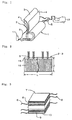
- Fig. 1 is a perspective view showing the structure of a wound-type internal electrode body.
- Fig. 2 is a plan view showing the spread state of each positive electrode and negative electrode in a wound-type internal electrode body.
- Fig. 3 is a perspective view showing one embodiment of the structure of a lamination-type internal electrode body.
- Fig. 4 is a cross-sectional view showing one embodiment of a method used to connect tabs to an electric current extracting terminal according to the lithium secondary battery of the present invention.
- Fig. 5 is an explanatory drawing showing another embodiment of a method used to connect tabs to an electric current extracting terminal according to the lithium secondary battery of the present invention.
- Fig. 6 is an explanatory drawing showing a method of measuring resistance of tabs according to the lithium secondary battery of the present invention.
- Fig. 7 is an explanatory drawing showing an embodiment of a method used to connect tabs to an electric current extracting terminal according to the lithium secondary battery of Comparative Example 2.
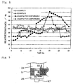
- Fig. 8 is an explanatory drawing showing the dispersion in resistance of tabs according to Examples and Comparative Examples.
- Fig. 9 is an explanatory drawing showing the flow of current from tabs to an electric current extracting terminal of a bolt and a nut.
- Fig. 10 is an explanatory drawing showing the flow of current from tabs to an electric current extracting terminal of a rivet.
- Fig. 11 is an explanatory drawing showing the process up to tab connection to an electric current extracting terminal in forming a lithium secondary battery of the present invention.
- Fig. 12 is an explanatory drawing showing the test results of cycle operations on an Example and Examples for comparison.
-
- The lithium secondary battery of this invention yields an excellent effect in that it is possible to discharge a huge electric current constantly, enabling uniform electricity collection from the positive electrode and negative electrode together with a uniform battery reaction within the positive electrode and negative electrode, since the resistance from the positive and negative electrodes to the electric current extracting terminal is uniformalized. As a result of this, it also yields another excellent effect in that local deterioration of battery materials may be suppressed and thus excellent endurance may be provided during cycle operations.
- The internal electrode body of the lithium secondary battery of the present invention (hereinafter referred to as a "battery") is constituted by a positive electrode, a negative electrode and a separator made of porous polymer film, the positive electrode and the negative electrode being wound or laminated so that the positive electrode and negative electrode are not brought into direct contact with each other via the separator. In particular, as shown in Fig. 1 before, an
internal electrode body 1 of a winding type is formed by winding apositive electrode 2 and anegative electrode 3 having aseparator 4 in between, andtabs 5 are provided forelectrodes - On the other hand, as shown in Fig. 3, the lamination-type
internal electrode body 7 laminates thepositive plate 8 and thenegative plate 9 alternately via theseparator 10 withtabs 6 being connected to the positive andnegative electrodes plates 8 and 9 (hereinafter referred to as "electrodes" 8, 9) respectively. Such aninternal electrode body positive electrodes negative electrodes - The
positive electrodes negative electrodes positive electrodes negative electrodes - For a battery with any of the above-described structures, lithium transition metal compound oxides such as lithium cobalt oxide (LiCoO2), lithium nickel oxide(LiNiO2), or lithium manganese oxide (LiMn2O4), etc., are generally used as positive active materials. In addition, in order to improve the conductivity of these positive active materials, a carbon powder such as acetylene black, graphite powder, etc., is frequently mixed with the electrode active material. On the other hand, as the negative active materials, an amorphous carbon material such as soft carbon or hard carbon, or carbon powder such as natural graphite, etc., is used.
- As a
separator - Next, the method of connection between the tabs and the internal electrode body (positive electrodes and negative electrodes) as well as the electric current extracting terminal will be explained using the case of a wound-type
internal electrode body 1 as an example. As described before, Fig. 2 is a plan view of theelectrodes internal electrode body 1 shown in Fig. 1 is spread out, wherein in the case of the battery capacity being constant, the length L toward its winding direction can be shortened if the width D of theelectrodes - However, in the case where the width D of the
electrodes tabs 5 and the electrodeactive material 16 in the vicinity of a side facing the side where thetabs 5 are attached becomes long. Therefore, normally the width of theelectrodes electrodes tabs 5 to be placed along the length L toward the winding direction ofelectrode - The tabs 5 (
tab 5A andtab 5B in Fig. 11) are preferably arranged to make an approximately straight line toward the direction of the diameter of theinternal electrode body 1 when theelectrodes tabs 5 to theelectrode terminal 13. - As a method for connecting the
electrodes tabs 5, resistance welding or ultrasonic welding may be used. There are no cases where the contact resistance between thetabs 5 and theelectrode tabs 5 and theelectrodes - Thus, the
tabs 5 disposed approximately at an almost equal distance respectively serve to transfer electrons having a relationship to the battery reaction in an approximately equal electrode area of theelectrodes terminal 13 to therespective tabs 5, there will arise dispersion in extraction of electricity as well. That is, there is a possibility that electricity will be concentrated inlow resistance tabs 5, and in this case, not only will the battery reaction be uneven, but also a problem will arise in that rapid deterioration of material will take place at the portions where the battery reaction will be most active (at the portions where thelow resistance tabs 5 are connected). - In order to avoid such a problem, according to the present invention, the
plural tabs 5, having been connected to eachelectrode tabs 5 at least remain within the range of ±20% of the average resistance value of thetabs 5. Due to this, it is preferred that all thetabs 5 are concentrated at one place and are connected to the electric current extractingterminal 13 by crimping or welding. - In particular, as shown in Fig. 4, it is possible to use a
rivet 22 as an electric current extractingterminal 13 to be attached to thebattery cap 23, and to collect thetabs 5 to connect to therivet 22 by crimping. In this case, based on the pressure used for the crimping, the resistance value of thetabs 5 can be within the above-described range. Incidentally, thetabs 5 may be connected to therivet 22 by welding instead of crimping, or thetabs 5 may be pressed into contact with therivet 22 and the connection part may be unified further by welding. - In addition, as shown in Fig. 5, using
metal plates 26 such as copper plates, aluminum plates and the like, all thetabs 5 are unified by crimping in advance, and thereafter fitted onto thebolt 24 which is an electric current extractingterminal 13 and there are screwed tightly by anut 25, a connection method that is used preferably. Incidentally, for unification of thetabs 5, in addition to crimping, a method such as welding or eyelet-type connecting may be employed, and for attaching theunified tabs 5 to the electric current extractingterminal 13, methods such as welding as well as crimping may be employed. - Now, as described before, since metal foils are used as the base material for the
electrodes tabs 5 in a thin band shape are preferably used as well, the thickness of which are preferred to be equal to or more than 5µm and equal to or less than 100µm. Here, in the present invention, aluminum foils are preferably used as the ones for the positive tabs and copper or nickel foils are preferably used as the ones for the negative tabs. - Incidentally, since connection points between the
tabs 5 and theelectrodes tabs 5 to the electric current extractingterminal 13 is only one, it is not preferred to use the shortest ones in length respectively for eachtab 5, giving rise to differences in resistance value for thetabs 5. Due to this, it is preferred to adjust the length of thetabs 5 for use to that of thetab 5 requiring the longest length, or whentabs 5 with different lengths are used, to equalize resistance values by adjusting their thickness and width. - Up until now, description has been centered on a wound-type
internal electrode body 1. It goes without saying that a similar description is applicable toelectrodes internal electrode body 7, where plural tabs are placed per plate of theelectrodes - By adopting the above-described battery structure, especially in a large capacity battery requiring placement of numerous tabs having a battery capacity of 5Ah or more, for example, for batteries for EV or HEV, a good charge-discharge characteristic becomes obtainable since electricity is extracted from the internal electrode bodies in the batteries equally through each tab.
- The present invention is described below by way of examples.
- When forming the battery, at first, in order to examine resistance dispersion due to differences in methods of tab connection to the electric current extracting terminal, 30 sheets of positive tabs made of bundled aluminum foil were crimped to a positive rivet made of aluminum, using a connection method that connects the
tabs 5 with arivet 22 which is an electric current extracting terminal by crimping as shown in Fig. 4, while 30 sheets of negative tabs made of bundled copper foil were crimped to a negative rivet made of copper. Thus, a positive rivet and a negative rivet to which tabs were crimped constitute a pair. Those with a pressure for crimping of 1 ton/cm2 are regarded as Example 1 and those with a pressure for crimping of 2 ton/cm2 are regarded as Example 2. - Next, as shown in Fig. 6, the resistance value for each
tab 5 was measured by measuring the voltage when a current of 1A flowed at eachtab 5 and therivet 22. The obtained resistance values were calculated to obtain an average value, and a resistance value distribution was obtained by standardizing the resistance values for eachtab 5 with the average value as 100%. - On the other hand, as Comparative Example 1, the
tabs 5 were crimped to therivet 22 by a similar method as adopted in the above-described Examples 1 and 2, setting pressure of 500 kg/cm2 for crimping, and the resistance value of eachtab 5 was measured. In addition, as Comparative Example forcomparison 2, as shown in Fig. 7, the resistance value of eachtab 5 was measured by a similar method as adopted in the above-described Examples 1 and 2, using an electric current extracting terminal consisting of abolt 24 and anut 25 without unifying the 30 sheets of thetabs 5 in advance, as shown in Fig. 5, but having a structure in which eachtab 5 is individually screwed tightly. - The dispersion in resistance values of the
tabs 5 in the above-described Examples 1, 2 and Comparative Examples 1, 2 is shown in Fig. 8. Examples 1, 2 show that dispersion in resistance values of thetabs 5 is within ±20% of the average value, while Comparative Examples show that the dispersion in resistance values is larger. - This result can be described as follows. That is, in the case of Comparative Example 2 where the
bolt 24 and thenut 25 were used, as shown in Fig. 9, thetabs 5 are provided with a hole to insert them into thescrew thread 27 of thebolt 24, the diameter of the hole being larger than the diameter of thescrew thread 27 of thebolt 24, and further the area where the side surface of the hole of thetabs 5 contacts thescrew thread 27 being fairly small due to the thinness of thetabs 5. Therefore, the current of eachtab 5 flows toward thebolt 24 through anadjacent tab 5, as shown by thearrow 50, or to thebolt 24 through anadjacent tab 5 and thenut 25, making it difficult for it to flow in the direction shown by thearrow 60. - On the other hand, as in the case of Examples 1, 2 and Comparative Example 1, the case of using the
rivet 22 is similar. In this case shown in Fig. 10, the current of eachtab 5 flows toward the direction shown by thearrow 50, namely to therivet 22 through anadjacent tab 5 since the area where the side surface of atab 5 contacts therivet 22 is fairly small, thus making it difficult for the current to flow in the direction shown by thearrow 60. - That is, in any case of the above-described Examples 1, 2, and Comparative Examples 1, 2, the current is to flow through the contact surface between the
tabs 5. Due to this, among the bundledtabs 5, ones located in the center will yield larger resistance values since there are more contact surfaces with thebolt 24 or therivet 22. - Therefore, it is necessary to reduce the resistance of the contact surfaces occurring at each
tab 5 so that dispersion in resistance values of therespective tabs 5 is reduced. Here it is known that for tabs made of aluminum foil, an insulating film of alumina is apt to be formed on its surface, and as the number of bundled thin-band-shapedtabs 5 increases, and the insulating film will have more effect on the resistance distribution of thetabs 5. Under the circumstances, it is necessary to destroy the insulating film, and thereby ensure contact at the metal material portion originating in the tab so as to reduce dispersion in resistance values of thetabs 5. - This is applicable to tabs made of copper foil. Nevertheless, since the oxide film to be generated on the surface of copper foil is a semiconductor, the contact surfaces are affected to a smaller extent than in the case where the aluminum foil is used. However, concerning the conductivity of electrons, since metal is naturally superior to a semiconductor, with regard to copper foil as well, it is preferable to ensure the contact between metals by destroying the oxide film on the surfaces.
- Therefore, a method capable of ensuring metal-to-metal contact by crimping is preferable for connecting the
tabs 5 to the electric current extracting terminal. In Examples 1, 2, it is thought that the dispersion in resistance of thetabs 5 was suppressed as a result of contact having been ensured between the metal materials with the oxide films on the surfaces of thetabs 5 having been destroyed by conducting crimping at an appropriate pressure. Nevertheless, it is thought that even if a crimping is used, as shown in the result of Comparative Example 1, in the case where the pressure of the crimping is low and inappropriate, dispersion in resistance of the connection oftabs 5 will increase, making the effect of crimping unobtainable. In addition, with Comparative Example 2, it is thought that with the clamp pressure for screwing it will be difficult to reach the necessary pressure to enable the oxide film on thetabs 5 to be destroyed, and as a result it is presumed that the dispersion of resistance became larger. - Incidentally, in order to limit dispersion in the resistance values of the
tabs 5 within an average value of ±20%, in the case where aluminum foil is used as thetabs 5, the pressure of crimping had to be within the range from 1 ton/cm2 to 50 ton/cm2, while in the case where copper foil is used, the pressure of the crimping had to be within the range from 500 kg/cm2 to 100 ton/cm2. - Thus, one of the reasons contributing to differences in the required range of pressure between aluminum foil and copper foil to limit dispersion in resistance values within a given range is thought to be due to the fact that an oxide film is more easily formed in an aluminum foil than in a copper foil, as well as due to the above-described difference in the electric characteristic of the oxide film. Incidentally, the upper limit of pressure for crimping for each
tab 5 is the pressure when damage such as cuts on thetab 5 take place at the end portions of therivet 22. - A lithium secondary battery was formed by the method described below. At first, a paste was formed with a LiMn2O4 powder body as a positive active material, to which acetylene black was added to provide conductivity to it, and further a binder and a solvent were mixed therein. With this paste being coated on both sides of 20µm-thick aluminum foil, a positive electrode was formed having an electrode plane shape with a length towards the winding direction of 3600mm × a width of 200mm. On the other hand, a paste was formed with a highly graphitized carbon powder as a positive active material, and further a binder and a solvent are mixed therein, which is then coated on both sides of 10µm-thick copper foil, and thereby a negative electrode was formed having an electrode plane shape with a length towards the winding direction of 4000mm × a width of 200mm.
- Next, as shown in Fig. 11, the thus-formed
positive electrode 2 andnegative electrode 3 were wound with insulation being provided employing 210mm-wide separators 4 made of polypropylene. At thesame time 30 sheets each ofpositive tabs 5A made of aluminum andnegative tabs 5B made of copper which were used in the above-described Example 1 were attached to theelectrodes internal electrode body 1, and so that eachelectrode internal electrode body 1. - The thus formed
internal electrode body 1 was fitted into the aluminum-madebattery case 17, crimping each positive tab andnegative tab negative electrode rivets negative rivet 22B to seal the negative side of thebattery case 17. Thereafter, from the open side of the positive terminal of thebattery case 17, the electrolyte, a mixed solvent of EC (ethylene carbonate) and DEC (diethyle carbonate) where electrolyte LiPF6 was dissolved to yield 1mol% density was injected into thebattery case 17. Thereafter, a battery cap was attached onto thepositive rivet 22A to tightly seal thebattery case 17. Incidentally, thebattery case 17 may be sealed from the positive side. - Thus, the battery formed using the method of connecting the tabs to the electric current extracting terminal in the above-described Example 1 is deemed to be the battery for the Example 1.
- Subsequently, respective batteries were formed, using the above-described Example 2 and Comparative Examples 1, 2 as the method for connecting the tabs to the electric current extracting terminal in the same way as in the battery for Example 1, except for the method used to connect the tabs to the electric current extracting terminal. The thus-formed batteries are deemed to be the battery for Example 2, the battery for Comparative Example 1, and the battery for Comparative Example 2 respectively.
- The battery capacity of the formed batteries was 25Ah, and their charge-discharge characteristic was assessed by a cycle operation test. Here, charging was conducted at a constant current of 25A and a constant voltage of 4.1V, and discharging was conducted with constant current at a discharge rate of 1C (25A) until discharge was finalized at 2.5V, whereupon charging/discharging was repeated. The discharge capacity for each time was standardized using the discharge capacity at the first time as 100%.
- Fig. 12 shows how the discharge capacity changed during the cycle operation test. For the batteries for Examples 1, 2 where the dispersion in resistance of the tabs was small, the capacity drop was small, and there were no major differences between the two. On the other hand, for the batteries for Comparative Example 2, where the dispersion in resistance of the tabs was large, the capacity drop was remarkable. Such a result is thought to be caused by unevenness that occurred in the battery reaction in the internal electrode body due to dispersion in resistance of the tabs, and deterioration which occurred partially in the positive electrodes and negative electrodes.
- As described above, the lithium secondary battery of this invention yields an excellent effect in that it is possible to discharge a huge electric current constantly, enabling uniform electricity collection from the positive electrodes and negative electrodes together with a uniform battery reaction within the positive electrodes and negative electrodes, since any inconsistency in the resistance of multiple tabs is limited within a certain range. As a result of this, it also yields another excellent effect in that local deterioration of battery materials may be suppressed and thus excellent endurance may be provided during cycle operations. A lithium secondary battery includes a battery case, an internal electrode body contained in the battery case and including a positive electrode, a negative electrode and a separator made of porous polymer. The positive electrode and the negative electrode are wound or laminated so that the positive electrode and negative electrode are not brought into direct contact with each other via the separator. The respective resistance value of multiple tabs for electricity collection to be connected with to the positive electrode and negative electrode was set to remain within the range of ±20% of the averaged resistance value of the tabs. The lithium secondary battery maintains a good charge-discharge characteristic even during high-output cycle operation and in particular may be preferably used for a drive motor of an electric vehicle.
Claims (6)
- A lithium secondary battery comprising:a battery case;an internal electrode body contained in the battery case and including a positive electrode, a negative electrode and a separator made of porous polymer, the positive electrode and the negative electrode being wound or laminated so that the positive electrode and negative electrode prevented by the separator from coming into direct contact with each other;multiple tabs for electricity collection;a positive terminal; anda negative terminal,each of said multiple tabs being connected at a first end to the positive electrode or the negative electrode and a second end to said positive terminal or said negative terminal, respectively, each of said multiple tabs having a resistance value set to remain within a range of ±20% of an average resistance value of the tabs, said resistance value of each tab being measured between said first end and the terminal to which said second end is connected.
- A lithium secondary battery according to claim 1, wherein all the positive tabs are connected to said positive terminal by crimping or welding, and all the negative tabs are connected to said negative terminal by crimping or welding.
- A lithium secondary battery according to claim 1, wherein all the positive tabs are unified by crimping or welding or eyelet-type connecting in advance and are thereafter connected to said positive terminal by crimping or welding or screwing, and all the negative tabs are unified by crimping or welding or eyelet-type connecting in advance, and are thereafter connected to said negative terminal by crimping or welding or screwing.
- A lithium secondary battery according to claim 1, wherein each said tab has a thickness within a range from 5 µm to 100 µm.
- A lithium secondary battery according to claim 1, wherein battery capacity is not less than 5 Ah.
- A lithium secondary battery according to claim 1, wherein the battery is used for an electric vehicle or a hybrid electric vehicle.
Applications Claiming Priority (4)
| Application Number | Priority Date | Filing Date | Title |
|---|---|---|---|
| JP6801798 | 1998-03-18 | ||
| JP6801798 | 1998-03-18 | ||
| JP17110598 | 1998-06-18 | ||
| JP17110598 | 1998-06-18 |
Publications (3)
| Publication Number | Publication Date |
|---|---|
| EP0949699A2 EP0949699A2 (en) | 1999-10-13 |
| EP0949699A3 EP0949699A3 (en) | 2004-01-28 |
| EP0949699B1 true EP0949699B1 (en) | 2005-06-01 |
Family
ID=26409254
Family Applications (1)
| Application Number | Title | Priority Date | Filing Date |
|---|---|---|---|
| EP99105468A Expired - Lifetime EP0949699B1 (en) | 1998-03-18 | 1999-03-17 | Electrical connection structure in a lithium secondary battery |
Country Status (4)
| Country | Link |
|---|---|
| US (1) | US6379840B2 (en) |
| EP (1) | EP0949699B1 (en) |
| CA (1) | CA2265324C (en) |
| DE (1) | DE69925532T2 (en) |
Cited By (4)
| Publication number | Priority date | Publication date | Assignee | Title |
|---|---|---|---|---|
| DE102007059443A1 (en) | 2007-12-10 | 2009-06-18 | Li-Tec Vermögensverwaltungs GmbH | Electrode for an energy storage |
| EP2141760A1 (en) | 2008-07-03 | 2010-01-06 | Li-Tec Battery GmbH | Electrode for an energy store device |
| DE202009013174U1 (en) | 2009-09-30 | 2011-02-17 | Li-Tec Battery Gmbh | Electrode for an energy storage |
| DE202009013179U1 (en) | 2009-09-30 | 2011-02-17 | Li-Tec Battery Gmbh | Electrode for an energy storage |
Families Citing this family (51)
| Publication number | Priority date | Publication date | Assignee | Title |
|---|---|---|---|---|
| US7041413B2 (en) * | 2000-02-02 | 2006-05-09 | Quallion Llc | Bipolar electronics package |
| US7166388B2 (en) | 2000-02-02 | 2007-01-23 | Quallion Llc | Brazed ceramic seal for batteries |
| US6607843B2 (en) * | 2000-02-02 | 2003-08-19 | Quallion Llc | Brazed ceramic seal for batteries with titanium-titanium-6A1-4V cases |
| US6605382B2 (en) * | 2000-04-26 | 2003-08-12 | Quallion Llc | Lithium ion battery suitable for hybrid electric vehicles |
| JP2002164044A (en) * | 2000-11-24 | 2002-06-07 | Nec Corp | Wound electrode battery and method of manufacturing the same |
| US7070881B2 (en) * | 2001-10-18 | 2006-07-04 | Quallion Llc | Electrical battery assembly and method of manufacture |
| US7332238B2 (en) * | 2002-09-06 | 2008-02-19 | The Gillette Company | Electrochemical cells and systems |
| CN100420087C (en) * | 2003-06-23 | 2008-09-17 | 比亚迪股份有限公司 | Laminated lithium-ion secondary battery |
| JP4461686B2 (en) * | 2003-02-13 | 2010-05-12 | トヨタ自動車株式会社 | Secondary battery, manufacturing apparatus and manufacturing method thereof |
| KR100624953B1 (en) * | 2004-11-29 | 2006-09-18 | 삼성에스디아이 주식회사 | Lithium secondary battery |
| EP2429010B1 (en) * | 2005-09-02 | 2014-12-17 | A123 Systems, Inc. | Battery cell design and method of its construction |
| US8084158B2 (en) * | 2005-09-02 | 2011-12-27 | A123 Systems, Inc. | Battery tab location design and method of construction |
| FR2904475B1 (en) * | 2006-07-28 | 2008-10-10 | Donald P H Wu | CONDUCTIVE STRUCTURE FOR AN ELECTRODE ASSEMBLY OF A LITHIUM SECONDARY BATTERY |
| DE102006054309A1 (en) * | 2006-11-17 | 2008-05-21 | Dieter Teckhaus | Battery cell with contact element arrangement |
| US8236441B2 (en) * | 2007-07-24 | 2012-08-07 | A123 Systems, Inc. | Battery cell design and methods of its construction |
| DE102008053011A1 (en) | 2008-10-23 | 2010-04-29 | Li-Tec Battery Gmbh | Galvanic cell for a rechargeable battery |
| DE102008052985A1 (en) | 2008-10-23 | 2010-04-29 | Li-Tec Battery Gmbh | Packaging device and packaging system for substantially flat objects, for example lithium-ion cells |
| DE102008053089A1 (en) | 2008-10-24 | 2010-04-29 | Li-Tec Battery Gmbh | Accumulator with several galvanic cells |
| JP2010135170A (en) * | 2008-12-04 | 2010-06-17 | Hitachi Vehicle Energy Ltd | Lithium secondary battery, secondary battery module, and secondary battery pack |
| US20100190056A1 (en) * | 2009-01-28 | 2010-07-29 | K2 Energy Solutions, Inc, | Battery Tab Structure |
| DE102009018804A1 (en) | 2009-04-24 | 2010-10-28 | Li-Tec Battery Gmbh | Electrochemical cell with lithium titanate |
| KR101222259B1 (en) * | 2009-11-18 | 2013-01-15 | 삼성에스디아이 주식회사 | Secondary Battery |
| KR101101046B1 (en) * | 2009-12-01 | 2011-12-29 | 삼성에스디아이 주식회사 | Electrode assembly and secondary battery having same |
| JP2012181941A (en) * | 2011-02-28 | 2012-09-20 | Mitsubishi Heavy Ind Ltd | Secondary battery |
| EP2742552A4 (en) * | 2011-08-08 | 2015-05-06 | Basf Se | ELECTROCHEMICAL CELLS |
| WO2014062702A1 (en) | 2012-10-16 | 2014-04-24 | Ambri, Inc. | Electrochemical energy storage devices and housings |
| US10541451B2 (en) | 2012-10-18 | 2020-01-21 | Ambri Inc. | Electrochemical energy storage devices |
| US9735450B2 (en) | 2012-10-18 | 2017-08-15 | Ambri Inc. | Electrochemical energy storage devices |
| US11721841B2 (en) | 2012-10-18 | 2023-08-08 | Ambri Inc. | Electrochemical energy storage devices |
| US9312522B2 (en) | 2012-10-18 | 2016-04-12 | Ambri Inc. | Electrochemical energy storage devices |
| US9520618B2 (en) | 2013-02-12 | 2016-12-13 | Ambri Inc. | Electrochemical energy storage devices |
| US11387497B2 (en) | 2012-10-18 | 2022-07-12 | Ambri Inc. | Electrochemical energy storage devices |
| US11211641B2 (en) | 2012-10-18 | 2021-12-28 | Ambri Inc. | Electrochemical energy storage devices |
| US10270139B1 (en) | 2013-03-14 | 2019-04-23 | Ambri Inc. | Systems and methods for recycling electrochemical energy storage devices |
| US9502737B2 (en) | 2013-05-23 | 2016-11-22 | Ambri Inc. | Voltage-enhanced energy storage devices |
| US12347832B2 (en) | 2013-09-18 | 2025-07-01 | Ambri, LLC | Electrochemical energy storage devices |
| DK3058605T3 (en) | 2013-10-16 | 2024-03-04 | Ambri Inc | SEALS FOR DEVICES OF REACTIVE HIGH TEMPERATURE MATERIAL |
| WO2015058165A1 (en) | 2013-10-17 | 2015-04-23 | Ambri Inc. | Battery management systems for energy storage devices |
| US12142735B1 (en) | 2013-11-01 | 2024-11-12 | Ambri, Inc. | Thermal management of liquid metal batteries |
| US10181800B1 (en) | 2015-03-02 | 2019-01-15 | Ambri Inc. | Power conversion systems for energy storage devices |
| WO2016141354A2 (en) | 2015-03-05 | 2016-09-09 | Ambri Inc. | Ceramic materials and seals for high temperature reactive material devices |
| US9893385B1 (en) | 2015-04-23 | 2018-02-13 | Ambri Inc. | Battery management systems for energy storage devices |
| US10181617B2 (en) | 2015-12-14 | 2019-01-15 | Johnson Controls Technology Company | Patterned crimp for battery collector attachment |
| US11929466B2 (en) | 2016-09-07 | 2024-03-12 | Ambri Inc. | Electrochemical energy storage devices |
| EP3607603A4 (en) | 2017-04-07 | 2021-01-13 | Ambri Inc. | MOLTEN SALT BATTERY WITH SOLID METAL CATHODE |
| KR102535745B1 (en) * | 2017-10-11 | 2023-05-23 | 삼성에스디아이 주식회사 | Secondary Battery |
| KR102659830B1 (en) | 2018-01-09 | 2024-04-23 | 삼성에스디아이 주식회사 | Secondary battery And Fabricating Method Thereof |
| JP2021518636A (en) | 2018-03-20 | 2021-08-02 | インディアン・スペース・リサーチ・オーガニゼイションIndian Space Research Organisation | Sealed lithium-ion battery and its manufacturing method |
| CN208000939U (en) * | 2018-04-11 | 2018-10-23 | 宁德新能源科技有限公司 | Battery and equipment |
| AU2019405440A1 (en) | 2018-12-17 | 2021-08-12 | Ambri, LLC | High temperature energy storage systems and methods |
| US12476258B2 (en) * | 2024-01-11 | 2025-11-18 | Rivian Ip Holdings, Llc | Battery cell with supplemental current collectors |
Family Cites Families (7)
| Publication number | Priority date | Publication date | Assignee | Title |
|---|---|---|---|---|
| US3884715A (en) * | 1972-02-23 | 1975-05-20 | Us Energy | Secondary electrochemical power-producing cells having mixed cathode composition |
| US5154993A (en) * | 1990-04-27 | 1992-10-13 | Eveready Battery Company, Inc. | Electrode strips for coiled assemblies and method of producing them |
| JPH07263028A (en) * | 1994-03-25 | 1995-10-13 | Fuji Photo Film Co Ltd | Nonaqueous secondary battery |
| US5736270A (en) * | 1995-06-08 | 1998-04-07 | Sony Corporation | Battery device |
| US6030726A (en) * | 1996-06-17 | 2000-02-29 | Hitachi, Ltd. | Lithium secondary battery having negative electrode of carbon material which bears metals |
| FR2752089B1 (en) * | 1996-07-30 | 1998-09-04 | Accumulateurs Fixes | CYLINDRICAL ELECTROCHEMICAL GENERATOR |
| FR2752092A1 (en) * | 1996-07-30 | 1998-02-06 | Accumulateurs Fixes | Electrochemical generator with spiral electrodes |
-
1999
- 1999-03-10 US US09/265,921 patent/US6379840B2/en not_active Expired - Fee Related
- 1999-03-16 CA CA002265324A patent/CA2265324C/en not_active Expired - Fee Related
- 1999-03-17 EP EP99105468A patent/EP0949699B1/en not_active Expired - Lifetime
- 1999-03-17 DE DE69925532T patent/DE69925532T2/en not_active Expired - Lifetime
Cited By (5)
| Publication number | Priority date | Publication date | Assignee | Title |
|---|---|---|---|---|
| DE102007059443A1 (en) | 2007-12-10 | 2009-06-18 | Li-Tec Vermögensverwaltungs GmbH | Electrode for an energy storage |
| EP2141760A1 (en) | 2008-07-03 | 2010-01-06 | Li-Tec Battery GmbH | Electrode for an energy store device |
| DE102008031537A1 (en) | 2008-07-03 | 2010-01-07 | Li-Tec Battery Gmbh | Electrode for an energy storage |
| DE202009013174U1 (en) | 2009-09-30 | 2011-02-17 | Li-Tec Battery Gmbh | Electrode for an energy storage |
| DE202009013179U1 (en) | 2009-09-30 | 2011-02-17 | Li-Tec Battery Gmbh | Electrode for an energy storage |
Also Published As
| Publication number | Publication date |
|---|---|
| DE69925532T2 (en) | 2006-04-27 |
| US6379840B2 (en) | 2002-04-30 |
| CA2265324C (en) | 2004-05-11 |
| EP0949699A2 (en) | 1999-10-13 |
| EP0949699A3 (en) | 2004-01-28 |
| CA2265324A1 (en) | 1999-09-18 |
| US20010038945A1 (en) | 2001-11-08 |
| DE69925532D1 (en) | 2005-07-07 |
Similar Documents
| Publication | Publication Date | Title |
|---|---|---|
| US6379840B2 (en) | Lithium secondary battery | |
| US6753104B2 (en) | Lithium secondary battery | |
| CN101141009B (en) | Assembled battery | |
| EP1636870B1 (en) | Stacked-type lithium-ion rechargeable battery | |
| US8119277B2 (en) | Stack type battery | |
| US9583783B2 (en) | Prismatic secondary battery | |
| US10177387B2 (en) | Bipolar battery current collector that contracts to interrupt a flow of electric current in a direction thereof and bipolar battery | |
| US9406921B2 (en) | Prismatic secondary battery | |
| CN101626093B (en) | Battery | |
| KR101841306B1 (en) | Electrode assembly comprising dfferent kind of separator comprising taping part for improving safety and lithium secondary batteries comprising the same | |
| KR102818895B1 (en) | Nonaqueous electrolyte secondary battery | |
| US20100216001A1 (en) | Rechargeable battery | |
| US20120214037A1 (en) | Lithium secondary battery | |
| KR20120026960A (en) | Battery and battery pack using the same | |
| US20110223455A1 (en) | Lithium-ion secondary cell | |
| JP4305111B2 (en) | Battery pack and electric vehicle | |
| JP3283805B2 (en) | Lithium secondary battery | |
| KR20080047165A (en) | Electrode assembly and secondary battery having same | |
| KR101495948B1 (en) | Pouched type secondary battery | |
| US7166387B2 (en) | Thin battery with an electrode having a higher strength base portion than a tip portion | |
| KR20130131983A (en) | Secondary battery comprising apparatus for preventing overcharge | |
| JP3511476B2 (en) | Lithium secondary battery | |
| US20240097201A1 (en) | Wound electrode body, secondary battery, and manufacturing method for the secondary battery | |
| JP3511966B2 (en) | Cylindrical lithium-ion battery | |
| US20250105436A1 (en) | Secondary battery |
Legal Events
| Date | Code | Title | Description |
|---|---|---|---|
| PUAI | Public reference made under article 153(3) epc to a published international application that has entered the european phase |
Free format text: ORIGINAL CODE: 0009012 |
|
| AK | Designated contracting states |
Kind code of ref document: A2 Designated state(s): AT BE CH CY DE DK ES FI FR GB GR IE IT LI LU MC NL PT SE |
|
| AX | Request for extension of the european patent |
Free format text: AL;LT;LV;MK;RO;SI |
|
| PUAL | Search report despatched |
Free format text: ORIGINAL CODE: 0009013 |
|
| AK | Designated contracting states |
Kind code of ref document: A3 Designated state(s): AT BE CH CY DE DK ES FI FR GB GR IE IT LI LU MC NL PT SE |
|
| AX | Request for extension of the european patent |
Extension state: AL LT LV MK RO SI |
|
| 17P | Request for examination filed |
Effective date: 20040602 |
|
| GRAP | Despatch of communication of intention to grant a patent |
Free format text: ORIGINAL CODE: EPIDOSNIGR1 |
|
| AKX | Designation fees paid |
Designated state(s): BE CH DE FR GB IT LI |
|
| GRAS | Grant fee paid |
Free format text: ORIGINAL CODE: EPIDOSNIGR3 |
|
| GRAA | (expected) grant |
Free format text: ORIGINAL CODE: 0009210 |
|
| AK | Designated contracting states |
Kind code of ref document: B1 Designated state(s): BE CH DE FR GB IT LI |
|
| PG25 | Lapsed in a contracting state [announced via postgrant information from national office to epo] |
Ref country code: IT Free format text: LAPSE BECAUSE OF FAILURE TO SUBMIT A TRANSLATION OF THE DESCRIPTION OR TO PAY THE FEE WITHIN THE PRESCRIBED TIME-LIMIT;WARNING: LAPSES OF ITALIAN PATENTS WITH EFFECTIVE DATE BEFORE 2007 MAY HAVE OCCURRED AT ANY TIME BEFORE 2007. THE CORRECT EFFECTIVE DATE MAY BE DIFFERENT FROM THE ONE RECORDED. Effective date: 20050601 |
|
| REG | Reference to a national code |
Ref country code: GB Ref legal event code: FG4D |
|
| REG | Reference to a national code |
Ref country code: CH Ref legal event code: EP |
|
| REG | Reference to a national code |
Ref country code: IE Ref legal event code: FG4D |
|
| REG | Reference to a national code |
Ref country code: CH Ref legal event code: NV Representative=s name: E. BLUM & CO. PATENTANWAELTE |
|
| REF | Corresponds to: |
Ref document number: 69925532 Country of ref document: DE Date of ref document: 20050707 Kind code of ref document: P |
|
| ET | Fr: translation filed | ||
| PGFP | Annual fee paid to national office [announced via postgrant information from national office to epo] |
Ref country code: BE Payment date: 20060323 Year of fee payment: 8 |
|
| PGFP | Annual fee paid to national office [announced via postgrant information from national office to epo] |
Ref country code: CH Payment date: 20060324 Year of fee payment: 8 |
|
| PLBE | No opposition filed within time limit |
Free format text: ORIGINAL CODE: 0009261 |
|
| STAA | Information on the status of an ep patent application or granted ep patent |
Free format text: STATUS: NO OPPOSITION FILED WITHIN TIME LIMIT |
|
| 26N | No opposition filed |
Effective date: 20060302 |
|
| REG | Reference to a national code |
Ref country code: CH Ref legal event code: PFA Owner name: NGK INSULATORS, LTD. Free format text: NGK INSULATORS, LTD.#2-56 SUDA-CHO, MIZUHO-KU#NAGOYA-CITY, AICHI PREFECTURE 467-8530 (JP) -TRANSFER TO- NGK INSULATORS, LTD.#2-56 SUDA-CHO, MIZUHO-KU#NAGOYA-CITY, AICHI PREFECTURE 467-8530 (JP) |
|
| REG | Reference to a national code |
Ref country code: CH Ref legal event code: PL |
|
| BERE | Be: lapsed |
Owner name: *NGK INSULATORS LTD Effective date: 20070331 |
|
| PG25 | Lapsed in a contracting state [announced via postgrant information from national office to epo] |
Ref country code: BE Free format text: LAPSE BECAUSE OF NON-PAYMENT OF DUE FEES Effective date: 20070331 |
|
| PG25 | Lapsed in a contracting state [announced via postgrant information from national office to epo] |
Ref country code: LI Free format text: LAPSE BECAUSE OF NON-PAYMENT OF DUE FEES Effective date: 20070331 Ref country code: CH Free format text: LAPSE BECAUSE OF NON-PAYMENT OF DUE FEES Effective date: 20070331 |
|
| PGFP | Annual fee paid to national office [announced via postgrant information from national office to epo] |
Ref country code: GB Payment date: 20080211 Year of fee payment: 10 |
|
| GBPC | Gb: european patent ceased through non-payment of renewal fee |
Effective date: 20090317 |
|
| PG25 | Lapsed in a contracting state [announced via postgrant information from national office to epo] |
Ref country code: GB Free format text: LAPSE BECAUSE OF NON-PAYMENT OF DUE FEES Effective date: 20090317 |
|
| PGFP | Annual fee paid to national office [announced via postgrant information from national office to epo] |
Ref country code: FR Payment date: 20130315 Year of fee payment: 15 |
|
| PGFP | Annual fee paid to national office [announced via postgrant information from national office to epo] |
Ref country code: DE Payment date: 20130328 Year of fee payment: 15 |
|
| REG | Reference to a national code |
Ref country code: DE Ref legal event code: R119 Ref document number: 69925532 Country of ref document: DE |
|
| REG | Reference to a national code |
Ref country code: FR Ref legal event code: ST Effective date: 20141128 |
|
| REG | Reference to a national code |
Ref country code: DE Ref legal event code: R119 Ref document number: 69925532 Country of ref document: DE Effective date: 20141001 |
|
| PG25 | Lapsed in a contracting state [announced via postgrant information from national office to epo] |
Ref country code: FR Free format text: LAPSE BECAUSE OF NON-PAYMENT OF DUE FEES Effective date: 20140331 Ref country code: DE Free format text: LAPSE BECAUSE OF NON-PAYMENT OF DUE FEES Effective date: 20141001 |