EP2141457A2 - Information display method, information processing apparatus, and information display program - Google Patents
Information display method, information processing apparatus, and information display program Download PDFInfo
- Publication number
- EP2141457A2 EP2141457A2 EP09251694A EP09251694A EP2141457A2 EP 2141457 A2 EP2141457 A2 EP 2141457A2 EP 09251694 A EP09251694 A EP 09251694A EP 09251694 A EP09251694 A EP 09251694A EP 2141457 A2 EP2141457 A2 EP 2141457A2
- Authority
- EP
- European Patent Office
- Prior art keywords
- map
- indication object
- position indication
- display mode
- display screen
- Prior art date
- Legal status (The legal status is an assumption and is not a legal conclusion. Google has not performed a legal analysis and makes no representation as to the accuracy of the status listed.)
- Granted
Links
Images






Classifications
-
- G—PHYSICS
- G06—COMPUTING OR CALCULATING; COUNTING
- G06F—ELECTRIC DIGITAL DATA PROCESSING
- G06F3/00—Input arrangements for transferring data to be processed into a form capable of being handled by the computer; Output arrangements for transferring data from processing unit to output unit, e.g. interface arrangements
- G06F3/01—Input arrangements or combined input and output arrangements for interaction between user and computer
- G06F3/048—Interaction techniques based on graphical user interfaces [GUI]
- G06F3/0484—Interaction techniques based on graphical user interfaces [GUI] for the control of specific functions or operations, e.g. selecting or manipulating an object, an image or a displayed text element, setting a parameter value or selecting a range
- G06F3/0485—Scrolling or panning
-
- G—PHYSICS
- G01—MEASURING; TESTING
- G01C—MEASURING DISTANCES, LEVELS OR BEARINGS; SURVEYING; NAVIGATION; GYROSCOPIC INSTRUMENTS; PHOTOGRAMMETRY OR VIDEOGRAMMETRY
- G01C21/00—Navigation; Navigational instruments not provided for in groups G01C1/00 - G01C19/00
- G01C21/26—Navigation; Navigational instruments not provided for in groups G01C1/00 - G01C19/00 specially adapted for navigation in a road network
- G01C21/34—Route searching; Route guidance
- G01C21/36—Input/output arrangements for on-board computers
- G01C21/3667—Display of a road map
- G01C21/367—Details, e.g. road map scale, orientation, zooming, illumination, level of detail, scrolling of road map or positioning of current position marker
Definitions
- the present invention relates to a method and apparatus for displaying a map on a display screen.
- Portable navigation apparatuses using the global positioning system (GPS) are widely used.
- a position indication object as a moving object, such as a human being, a device, or a vehicle, on a map using location log data.
- a position indication object measured as a current position is indicated by a cursor on a map.
- the map is scrolled while the cursor is fixed at a certain point, e.g., the center point of the display screen.
- map information can be provided appropriately.
- the moving speed increases, for example, as the moving state of a user changes from walking to running, the map is scrolled too fast at the scale suitable for the preceding moving speed. In some cases, information is not read out accurately.
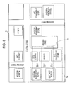
- Fig. 3 illustrates a map 5 showing an area where the user walks or runs.
- a Central Street running east to west
- an Eastern Street and a Western Street each running north to south, various facilities, and schools are located.
- FIG. 15A part of the map 5 shown in Fig. 3 is displayed as a map 5a on a display screen 1 at time t1.
- a cursor 9a indicating the current position of the user is displayed at the center of the display screen 1 (map 5a).
- a landmark of the East West Museum is displayed as part of the map 5a on the display screen 1 and information 7 including, for example, a photo and text about the East West Museum is displayed in the vicinity of the landmark.
- a map 5f showing an area considerably shifted from that shown by the map 5e is displayed on the display screen 1.
- the information 7 including the photo and text about the East West Museum is not displayed at time t2.
- the landmark of the East West Museum is not displayed at time t3. Consequently, it is difficult to reliably read information.
- an information display method whereby an information processing apparatus displays a map on a display screen such that a cursor is displayed at a position measured as the current position of a position indication object on the map.
- the method includes the steps of, when the moving speed of the position indication object is equal to or less than a threshold speed, scrolling the map on the display screen in accordance with the movement of the position indication object in a first display mode, and when the moving speed of the position indication object is greater than the threshold speed, fixing the map on the display screen in a second display mode or reducing the speed of scrolling the map on the display screen so that the scrolling speed is lower than that in the first display mode.
- the map when the moving speed of the position indication object is greater than the threshold speed, the map is fixed on the display screen without being scrolled, alternatively, the map is scrolled on the display screen at a lower speed. Accordingly, information is displayed on the display screen for a long time so that necessary information can be reliably read.
- a cursor (mark) indicating an object whose position is to be indicated (hereinafter, “position indication object”) can be displayed at a position, measured as the current position of the position indication object, on the map.
- the invention provides an information processing apparatus comprising: a processing unit configured to display a map on a display screen such that a cursor is displayed at a position measured as the current position of a position indication object on the map; and a control unit configured to, when an interobject distance, serving as the distance between a first position indication object and a second position indication object, is equal to or greater than a threshold distance, display a map on the display screen at a first scale in a first display mode such that the cursor indicating the first position indication object is displayed on the map and, when the interobject distance is less than the threshold distance, display a map on the display screen at a second scale smaller than the first scale in a second display mode such that the cursor indicating the first position indication object and another cursor indicating the second position indication object are displayed on the map.
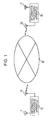
- Fig. 1 illustrates an information display system that performs an information display method according to an embodiment of the present invention.
- the information display system includes information processing apparatuses 10 and 20, each having a positioning function and a radio communication function, such that the information processing apparatuses are connected through the respective radio communication functions to each other via a network 30.
- the information processing apparatus 10 is used by a user A.
- the user A carries the information processing apparatus 10.
- the information processing apparatus 10 is installed in a vehicle in which the user A rides.
- the information processing apparatus 20 is used by a user B.
- the user B carries the information processing apparatus 20.
- the information processing apparatus 20 is installed in a vehicle in which the user B rides.
- Fig. 2 illustrates exemplary configurations of the information processing apparatuses 10 and 20.
- the information processing apparatus 10 includes a GPS antenna 11, a GPS arithmetic unit 12, a control unit 13, a storage unit 14, an operation unit 15, a display processing unit 16, a display unit 17, a radio communication unit 18, and a radio communication antenna 19.
- the GPS antenna 11 receives a radio wave from a GPS satellite.
- the GPS arithmetic unit 12 demodulates a received signal and performs an arithmetic operation on the signal to measure the position of the information processing apparatus 10.
- the control unit 13 controls respective units of the information processing apparatus 10. Although components of the control unit 13 are not shown in the figure, the control unit 13 includes a CPU, a ROM in which a program to be executed by the CPU and fixed data, and a RAM in which a program or data is developed.
- the storage unit 14 functioning as a bulk memory, stores map information and content information.
- the information display system may be designed so that the information processing apparatus 10 acquires map information from a server, connected thereto, of the user A or a service provider's server connected to the network 30.
- the operation unit 15 is operated by the user A to perform various operations on the information processing apparatus 10.
- the display processing unit 16 displays a map and necessary information on a display screen of the display unit 17 on the basis of information, e.g., the map information stored in the storage unit 14 and location information obtained by the GPS arithmetic unit 12 as will be described later.
- the display unit 17 includes a display, such as a liquid crystal display or an organic electroluminescent (EL) display.
- a display such as a liquid crystal display or an organic electroluminescent (EL) display.
- the radio communication unit 18 transmits location information, obtained by the GPS arithmetic unit 12, as information indicating the current position of the information processing apparatus 10 to the information processing apparatus 20 and also receives location information, transmitted from the information processing apparatus 20, as information indicating the current position of the information processing apparatus 20.
- the information processing apparatus 20 also includes a GPS antenna 21, a GPS arithmetic unit 22, a control unit 23, a storage unit 24, an operation unit 25, a display processing unit 26, a display unit 27, a radio communication unit 28, and a radio communication antenna 29.
- the configurations and operations of the respective components are the same as those in the information processing apparatus 10.
- the information display method includes a single-point display mode and a multi-point display mode.
- each of the information processing apparatuses 10 and 20 displays a map on the display screen such that a cursor indicating the apparatus is displayed at the position of the apparatus on the map.
- each of the information processing apparatuses 10 and 20 displays a map on the display screen such that a cursor indicating the position of the apparatus and another cursor indicating the position of another apparatus are simultaneously displayed at the position of the apparatus and that of the other apparatus, respectively.
- FIG. 1 and 2 another apparatus for the information processing apparatus 10 is the information processing apparatus 20 and that for the information processing apparatus 20 is the information processing apparatus 10.
- the position of the information processing apparatus 10 is the position of the user A.
- the position of the information processing apparatus 10 is the position of the vehicle and is also that of the user A.
- the position of the information processing apparatus 20 is the position of the user B.
- the position of the information processing apparatus 20 is the position of the vehicle and is also that of the user B.
- the position of the information processing apparatus 10 is that of the user A and the position of the information processing apparatus 20 is that of the user B.
- the scale of a map is expressed by a fraction of 1/M
- the map scale is small, namely, the ratio is small.
- the map scale is large, namely, the ratio is large.
- the single-point display mode in the information processing apparatus 10 is exactly the same as that in the information processing apparatus 20. Accordingly, the single-point display mode in the information processing apparatus 10 will now be described below.
- the moving speed of the user A is equal to or less than a threshold speed Vth before time t1 and the moving speed of the user A is greater than the threshold speed Vth at time t1.
- a map scroll mode is set up to time t1.
- the map is scrolled at a scroll speed suitable for the moving speed of the user A on the display screen.
- the cursor indicating the user A is displayed so as to be fixed at a certain point on the display screen, for example, the center thereof.
- part of the map 5 in Fig. 3 is displayed as a map 5a on the display screen 1 and the cursor, indicated at 9a, is displayed at the center of the display screen 1 (the map 5a).
- information 7 including a photo and text about the East West Museum is displayed in the vicinity of a landmark of the East West Museum.
- the display mode is switched from the map scroll mode to a map fixed mode.
- the threshold speed Vth is set to a proper value in accordance with the map scale in the map scroll mode.
- the map In the map fixed mode, the map is not scrolled on the display screen 1.
- the map 5a is displayed as it is on the display screen 1. Specifically, when the moving speed of the user A is greater than the threshold speed Vth, the map is fixed on the display screen 1 without being scrolled at a high scroll speed suitable for the moving speed of the user A.
- the cursor 9a moves on the display screen 1 (the map 5a).
- the cursor 9a is displayed in the vicinity of the upper end of the display screen 1 as shown in Fig. 4B .
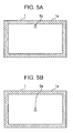
- the map is shifted on the display screen 1, so that the cursor 9a is shifted inward from the peripheral portion 1a of the display screen 1 as shown in Fig. 5B .
- Fig. 4C illustrates a case where a map 5b, shifted from the map 5a of Fig. 4B , showing another part of the map 5 of Fig. 3 is displayed on the display screen 1 and the shifted cursor 9a is displayed at the center of the display screen 1.
- Map changing in this case is different from that by scrolling the map in the map scroll mode.
- the map displayed on the display screen 1 is instantaneously changed to another one.
- the map 5b is displayed on the display screen 1 in the map fixed mode without being scrolled.
- map display namely, the map is displayed such that the moving direction of a position indication object is upward on the display screen and the position indication object moves toward the north.
- Map display including that in the multi-point display mode, is generally performed as shown in Fig. 6 .
- a map showing area 5A is part displayed on the display screen before changing.
- a map showing area 5B is another part displayed on the display screen after changing.
- P1(0, 0), P2(X, 0), P3(0, Y), and P4(X, Y) correspond to the upper left corner, the upper right corner, the lower left corner, and the lower right corner of the map showing area 5A, respectively.
- X denotes the size (the number of pixels) in the lateral direction of each of the map showing areas 5A and 5B.
- Y denotes the size (the number of pixels) in the longitudinal direction of each of the map showing areas 5A and 5B.
- a peripheral portion 6A shown by hatching is set.
- Pa(x, y) denote a point indicated by the cursor 9a in the map showing area 5A.
- the map displayed on the display screen 1 is changed from the map showing area 5A to the map showing area 5B when the point Pa(x, y) is located within the peripheral portion 6A, namely, any of the following relationships is satisfied: 0 ⁇ x ⁇ wx ; X - wx ⁇ x ⁇ X ; 0 ⁇ y ⁇ wy ; and Y - wy ⁇ y ⁇ Y .
- the map showing area 5B after changing is set so that the point Pa(x, y) indicated by the cursor 9a is located on the map showing area 5B as follows.
- ⁇ denote a distance from the inner edge of a peripheral portion 6B in the case where the peripheral portion 6B is set in the map showing area 5B in a manner similar to the map showing area 5A.
- the distance ⁇ is set to an appropriate value so that the point Pa(x, y) indicated by the cursor 9a on the map showing area 5B is located inside the inner edge of the peripheral portion 6B.
- the map showing area 5B is used as a map showing area before changing. Whether the map showing area is changed is determined on the basis of whether the above-described conditions for changing are satisfied. When the map showing area is changed, the area is changed in the above-described manner.
- the display mode is contrarily switched from the map fixed mode to the map scroll mode.
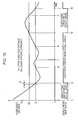
- the moving speed, indicated at Vt, of the user A is greater than the threshold speed Vth at time ta and, after that, the moving speed Vt varies around the threshold speed Vth so as to be at the threshold speed Vth at time points tb, tc, td, te, and tf.
- the display mode be changed at each of the time pointes tb, tc, td, te, and tf.
- the threshold speed Vth is set as an upper threshold speed and a threshold speed Vtl lower than the threshold speed Vth is set as a lower threshold speed so that hysteresis is provided for changing the display mode as follows.
- a unit time Ts shown in Fig. 7 is a time interval between a sampling time point and the next sampling time point in a result of position measurement.
- the moving speed Vt is obtained by dividing the unit time Ts into a distance Ds in which the user A moved for a period corresponding to the unit time Ts, namely, the moving speed Vt is expressed as Ds/Ts.
- the distance Ds is calculated from a measured position.
- a moving speed Vt(n) at time t(n) is greater than a moving speed Vt(n-1) at time t(n-1) earlier than time t(n) by the unit time Ts.
- the moving speed Vt when the moving speed Vt is decreasing, the moving speed Vt(n) at time t(n) is less than the moving speed Vt(n-1) at time t(n-1) earlier than time t(n) by the unit time Ts.
- whether the moving speed Vt is increasing or decreasing is determined by comparing the moving speed Vt(n) at time t(n) with the moving speed Vt(n-1) at time t(n-1) earlier than time t(n) by the unit time Ts.
- the display mode is switched from the map scroll mode to the map fixed mode as described above.
- the map fixed mode is not switched to the map scroll mode.
- the map fixed mode is switched to the map scroll mode.
- the display mode is switched from the map scroll mode to the map fixed mode at time ta.
- the map fixed mode is switched to the map scroll mode at time tg.
- the map scroll mode is switched to the map fixed mode at time ti after time th following time tg.
- this prevents the problem that the display mode is often changed in a short time due to a variation in the moving speed Vt within a small range in the short time.
- each of the information processing apparatuses 10 and 20 can display a map on the display screen such that a cursor indicating the apparatus and another cursor indicating another apparatus can be simultaneously displayed in the position of the apparatus and that of the other apparatus on the map, respectively.
- the multi-point display mode in the information processing apparatus 10 is exactly the same as that in the information processing apparatus 20. Accordingly, the multi-point display mode in the information processing apparatus 10 will be described below.
- the single-point display mode is set so that the scale of a map to be displayed on the display screen is relatively large (the denominator of the scale is relatively small), the map showing a relatively small area is displayed on the display screen, and only the cursor indicating the user A is displayed on the display screen 1.
- the map 5a is displayed as part of the map 5 shown in Fig. 8 on the display screen 1 and the cursor 9a is displayed at the center of the display screen 1 (map 5a).
- the display mode is switched between the map scroll mode and the map fixed mode in accordance with the moving speed Vt of the user A.
- the map showing area is changed as described above with reference to Figs. 5A to 6 so that the cursor 9a does not disappear from the display screen 1.
- the distance between the users A and B (the information processing apparatuses 10 and 20) is detected as an interobject distance every sampling time as a result of position measurement by the information processing apparatuses 10 and 20.
- the users A and B are located at positions corresponding to points Pa1 and Pb1 on the map 5, respectively, as shown in Fig. 8 .
- the interobject distance is the distance in a straight line (hereinafter, "straight-line distance") between the points Pa1 and Pb1.
- the users A and B are located at positions corresponding to points Pa2 and Pb2 on the map 5, respectively.
- the interobject distance is the straight-line distance between the points Pa2 and Pb2.
- the display mode when the interobject distance is less than a threshold distance Dtl, the display mode is switched from the single-point display mode to the multi-point display mode.
- the threshold distance Dtl is set to an appropriate value in accordance with a map scale in the single-point display mode.
- the interobject distance is equal to or less than the threshold distance Dtl up to time t1
- the interobject distance is less than the threshold distance Dtl at time t2.
- the display mode is switched from the single-point display mode to the multi-point display mode at time t2.
- the scale of a map displayed on the display screen is smaller than that in the single-point display mode.
- a map 5c showing an area larger than that in the single-point display mode is displayed on the display screen 1.
- the map 5c includes the respective current positions of the users A and B.
- the cursor 9a indicating the current position of the user A and a cursor 9b indicating the current position of the user B are simultaneously displayed.
- the user A finds that the users A and B are located within a predetermined range.
- the user B since similar display processing is performed, the user B also finds that the users B and A are located in the predetermined range.
- the map scroll mode is not used in the multi-point display mode.
- the map fixed mode alone is used.
- the map showing area is changed as described above. At that time, the map showing area is changed so that the current positions of both the users A and B are located within the changed map showing area.
- the display mode is switched from the multi-point display mode to the single-point display mode.
- the interobject distance, indicated at Dt is less than the threshold distance Dtl at time tp and, after that, the interobject distance Dt varies around the threshold distance Dtl so as to be at the threshold distance Dtl at time points tq, tr, and ts.
- the display mode be changed at each of the time points tq, tr, and ts.
- the threshold distance Dtl is set as a lower threshold distance and a threshold distance Dth greater than the threshold distance Dtl is set as an upper threshold distance so that hysteresis is provided for changing the display mode as follows.
- the unit time Ts shown in Fig. 10 is the time interval between a certain sampling time and the next sampling time in a result of position measurement.
- an interobject distance Dt(n) at time t(n) is less than an interobject distance Dt(n-1) at time t(n-1) earlier than time t(n) by the unit time Ts.
- the interobject distance Dt(n) at time t(n) is greater than the interobject distance Dt(n-1) at time t(n-1) earlier than time t(n) by the unit time Ts.
- whether the interobject distance Dt is decreasing or increasing is determined by comparing the interobject distance Dt(n) at time t(n) with the interobject distance Dt(n-1) at time t(n-1) earlier than time t(n) by the unit time Ts.
- the display mode is switched from the single-point display mode to the multi-point display mode as described above.
- the display mode is not switched to the single-point display mode.
- the display mode is switched to the single-point display mode.
- the display mode is switched from the single-point display mode to the multi-point display mode at time tp.
- the multi-point display mode is switched to the single-point display mode at time tu.
- the single-point display mode is switched to the multi-point display mode at time tw after time tv following time tu.
- this prevents the problem that the display mode is often changed in a short time due to a variation in the interobject distance Dt within a small range in the short time.
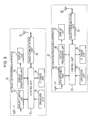
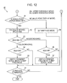
- Figs. 11 and 12 illustrate a series of processing steps related to the above-described display mode setting performed by the information processing apparatus 10.
- the display mode setting process is started when the information processing apparatus 10 is turned on or the user A performs a starting operation.
- the single-point display mode and the map scroll mode are set as initial display modes.
- step 42 the current interobject distance Dt(n) is calculated as described above with reference to Fig. 10 .
- step 43 a determination is made as to whether the calculated current interobject distance Dt(n) is less than the preceding interobject distance Dt(n-1) obtained earlier by the unit time Ts.
- step 43 When the current interobject distance Dt(n) is less than the preceding interobject distance Dt(n-1), it is determined that the interobject distance Dt is decreasing. The process proceeds from step 43 to step 44.
- step 44 a determination is made as to whether the interobject distance Dt(n) is less than the lower threshold distance Dtl.
- step 44 the process proceeds from step 44 to step 45.
- step 45 the display mode is switched from the single-point display mode to the multi-point display mode as shown at time tp or tw in Fig. 10 . The process then proceeds to step 51.
- step 44 When the interobject distance Dt(n) is equal to or greater than the lower threshold distance Dtl, the process proceeds from step 44 to step 51.
- step 46 a determination is made as to whether the interobject distance Dt(n) is greater than the upper threshold distance Dth.
- step 46 the display mode is switched from the multi-point display mode to the single-point display mode as shown at time tu in Fig. 10 .
- the process proceeds to step 51.
- step 46 When the interobject distance Dt(n) is equal to or less than the upper threshold distance Dth, the process proceeds from step 46 to step 51.
- step 51 a determination is made as to whether the display mode set at that time is the single-point display mode.
- step 51 When the display mode set at that time is the single-point display mode, the process proceeds from step 51 to step 52.
- the current moving speed Vt(n) is calculated as described above with reference to Fig. 7 .
- step 53 a determination is made as to whether the calculated current moving speed Vt(n) is greater than the preceding moving speed Vt(n-1) obtained earlier by the unit time Ts.
- step 53 When the current moving speed Vt(n) is greater than the preceding moving speed Vt(n-1), it is determined that the moving speed Vt is increasing. The process proceeds from step 53 to step 54.
- step 54 a determination is made as to whether the moving speed Vt(n) is greater than the upper threshold speed Vth.
- step 54 When the moving speed Vt(n) is greater than the upper threshold speed Vth, the process proceeds from step 54 to step 55.
- the display mode In the single-point display mode, the display mode is switched from the map scroll mode to the map fixed mode as shown at time ta or ti in Fig. 7 .
- the process proceeds to step 61.
- step 54 When the moving speed Vt(n) is equal to or less than the upper threshold speed Vth, the process proceeds from step 54 to step 61.
- step 56 a determination is made as to whether the moving speed Vt(n) is less than the lower threshold speed Vtl.
- step 56 When the moving speed Vt(n) is less than the lower threshold speed Vtl, the process proceeds from step 56 to step 57.
- the display mode In the single-point display mode, the display mode is switched from the map fixed mode to the map scroll mode as shown at time tg in Fig. 7 . The process proceeds to step 61.
- step 56 When the moving speed Vt(n) is equal to or less than the lower threshold speed Vtl, the process proceeds from step 56 to step 61.
- step 51 When it is determined in step 51 that the display mode set at that time is not the single-point display mode but the multi-point display mode, the display mode is set not to the map scroll mode but to the map fixed mode in step 59. The process proceeds to step 61.
- step 61 a determination is made as to whether the process related to display mode setting is terminated.
- the process is terminated in accordance with a terminating operation by the user A.
- the process is returned to step 42. Step 42 and the subsequent steps are repeated.
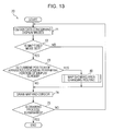
- Fig. 13 illustrates a drawing routine for information display, performed by the information processing apparatus 10, in the display modes set as described above.
- This drawing routine, indicated at 70, is performed concurrently with the above-described display mode setting process 40 every sampling time as a result of position measurement.
- step 71 data concerning the display modes set as described above is obtained.
- step 72 a determination is made as to whether the map fixed mode is set.
- either the map scroll mode or the map fixed mode is used in the single-point display mode.
- the multi-point display mode only the map fixed mode is used.
- step 72 When the map fixed mode is set, the process proceeds from step 72 to step 73.
- step 73 a determination is made as to whether the current position of the apparatus (information processing apparatus 10) is located in the peripheral portion of the display screen as described above with reference to Figs. 5A to 6 .
- step 73 When the current position of the apparatus is located in the peripheral portion of the display screen, the process proceeds from step 73 to a map showing area changing routine 80.
- a map showing area changing process is executed as will be described later. After that, the process proceeds step 74.
- step 73 When the current position of the apparatus is not located in the peripheral portion of the display screen, the process proceeds from step 73 to step 74.
- step 72 When it is determined in step 72 that the set display mode is not the map fixed mode but the map scroll mode is set in the single-point display mode, the process proceeds from step 72 to step 74.
- step 74 a map and a cursor are drawn. The process then proceeds to step 75.
- step 75 a determination is made as to whether the drawing process is terminated. When the drawing process is not terminated but is continued, the process is returned to step 71. Step 71 and the subsequent steps are repeated.
- Fig. 14 illustrates the map showing area changing routine 80 shown in Fig. 13 .
- a determination is made as to whether the set display mode is the single-point display mode.
- step 82 a map showing area after changing is determined as described above with reference to Fig. 6 .
- step 83 a determination is made as to whether it is possible to display the current position of the apparatus and that of the other apparatus on the same map at the same scale as that in the single-point display mode.
- step 83 When it is difficult to display the current position of the apparatus and that of the other apparatus on the same map at the same scale as that in the single-point display mode, the process proceeds from step 83 to step 84.
- step 84 the map scale is reduced. After that, the process is returned to step 83.
- step 83 When it is determined in step 83 that it is possible to display the current position of the apparatus and that of the other apparatus on the same map at the same scale as that in the single-point display mode or the map scale reduced in step 84, the process proceeds step 82.
- step 82 a map showing area after changing is determined.
- the map display mode is switched to the map fixed mode. While the map is not fixed on the display screen and the map scale is set smaller than that in the map scroll mode, the map scroll speed on the display screen may be reduced.
- a first position indication object may be set to an information processing apparatus having a positioning function or a user and a second position indication object may be set to a fixed location or point such as a destination or an objective point.
- the display mode is switched from the single-point display mode to the multi-point display mode so that the current position and the destination are simultaneously displayed on the map.
- the number of position indication objects is not limited to two. Three or more position indication objects may be used. For example, assuming that the number of position indication objects is three, when the distance between specific two objects, that between any two of the three objects, or that between each two of the three objects is less than the lower threshold distance, the two or three objects are simultaneously displayed on the map.
- the position of a position indication object is displayed in real time.
- the approach described herein is applicable to a case where the position of a position indication object is displayed in non-real time on the basis of recorded location log data.
- the information processing apparatus 10 records location information, obtained as a result of position measurement by the GPS arithmetic unit 12, together with time information indicating the time of position measurement into the storage unit 14.
- the information processing apparatus 20 also records location information, obtained as a result of position measurement by the GPS arithmetic unit 22, together with time information indicating the time of position measurement into the storage unit 24.
- the location information is supplied from the storage unit 14 or 24 to an information processing apparatus, such as a personal computer (PC).
- the information processing apparatus displays a position measured as the current position of the information processing apparatus 10 or 20 in non-real time.
Landscapes
- Engineering & Computer Science (AREA)
- Radar, Positioning & Navigation (AREA)
- Remote Sensing (AREA)
- Physics & Mathematics (AREA)
- General Physics & Mathematics (AREA)
- General Engineering & Computer Science (AREA)
- Theoretical Computer Science (AREA)
- Automation & Control Theory (AREA)
- Human Computer Interaction (AREA)
- Navigation (AREA)
- Instructional Devices (AREA)
- User Interface Of Digital Computer (AREA)
Abstract
Description
- The present invention relates to a method and apparatus for displaying a map on a display screen.
- Portable navigation apparatuses using the global positioning system (GPS) are widely used.
- In addition, there are many pieces of software for indicating the position of a position indication object as a moving object, such as a human being, a device, or a vehicle, on a map using location log data.
- It is assumed that the position of a position indication object measured as a current position is indicated by a cursor on a map. According to a typical method, when the position indication object moves, the map is scrolled while the cursor is fixed at a certain point, e.g., the center point of the display screen.
- According to an apparatus disclosed in Japanese Unexamined Patent Application Publication No.
4-45476 - According to the above-described method in which the map is scrolled while the cursor indicating the position of the position indication object is fixed at a certain point on the display screen, so long as the relationship between the scale of the map and the moving speed of the position indication object is appropriate, map information can be provided appropriately.
- If the moving speed increases, for example, as the moving state of a user changes from walking to running, the map is scrolled too fast at the scale suitable for the preceding moving speed. In some cases, information is not read out accurately.
-
Fig. 3 illustrates amap 5 showing an area where the user walks or runs. In the area shown by themap 5, a Central Street running east to west, an Eastern Street and a Western Street each running north to south, various facilities, and schools are located. - It is assumed that the user walks or runs along the Western Street toward the north and passes the East West Museum at time t1.
- Referring to
Fig. 15A , part of themap 5 shown inFig. 3 is displayed as amap 5a on adisplay screen 1 at time t1. Acursor 9a indicating the current position of the user is displayed at the center of the display screen 1 (map 5a). - At that time, a landmark of the East West Museum is displayed as part of the
map 5a on thedisplay screen 1 andinformation 7 including, for example, a photo and text about the East West Museum is displayed in the vicinity of the landmark. - When the user moves at high speed in the above situation, the map is scrolled at high speed on the
display screen 1. At time t2 after a lapse of predetermined time from time t1, as shown inFig. 15B , amap 5e showing an area considerably shifted from that shown by themap 5a is displayed on thedisplay screen 1. - At time t3 after a lapse of predetermined time from time t2, as shown in
Fig. 15C , a map 5f showing an area considerably shifted from that shown by themap 5e is displayed on thedisplay screen 1. - Accordingly, the
information 7 including the photo and text about the East West Museum is not displayed at time t2. The landmark of the East West Museum is not displayed at time t3. Consequently, it is difficult to reliably read information. - It is desirable to reliably read necessary information even when the moving speed of a position indication object is high.
- Various respective aspects and features of the invention are defined in the appended claims. Combinations of features from the dependent claims may be combined with features of the independent claims as appropriate and not merely as explicitly set out in the claims.
- According to an embodiment of the present invention, there is provided an information display method whereby an information processing apparatus displays a map on a display screen such that a cursor is displayed at a position measured as the current position of a position indication object on the map. The method includes the steps of, when the moving speed of the position indication object is equal to or less than a threshold speed, scrolling the map on the display screen in accordance with the movement of the position indication object in a first display mode, and when the moving speed of the position indication object is greater than the threshold speed, fixing the map on the display screen in a second display mode or reducing the speed of scrolling the map on the display screen so that the scrolling speed is lower than that in the first display mode.
- According to this method in accordance with the embodiment of the present invention, when the moving speed of the position indication object is greater than the threshold speed, the map is fixed on the display screen without being scrolled, alternatively, the map is scrolled on the display screen at a lower speed. Accordingly, information is displayed on the display screen for a long time so that necessary information can be reliably read.
- As described above, according to the embodiment of the present invention, even when the moving speed of a position indication object is high, necessary information can be reliably read.
- In such an approach a cursor (mark) indicating an object whose position is to be indicated (hereinafter, "position indication object") can be displayed at a position, measured as the current position of the position indication object, on the map.
- Viewed from another aspect, the invention provides an information processing apparatus comprising: a processing unit configured to display a map on a display screen such that a cursor is displayed at a position measured as the current position of a position indication object on the map; and a control unit configured to, when an interobject distance, serving as the distance between a first position indication object and a second position indication object, is equal to or greater than a threshold distance, display a map on the display screen at a first scale in a first display mode such that the cursor indicating the first position indication object is displayed on the map and, when the interobject distance is less than the threshold distance, display a map on the display screen at a second scale smaller than the first scale in a second display mode such that the cursor indicating the first position indication object and another cursor indicating the second position indication object are displayed on the map.
- Embodiments of the invention will now be described with reference to the accompanying drawings, throughout which like parts are referred to by like references, and in which:
-
Fig. 1 is a diagram illustrating an information display system that performs an information display method according to an embodiment of the present invention; -
Fig. 2 is a diagram illustrating information processing apparatuses in the embodiment; -
Fig. 3 is a diagram illustrating a map; -
Figs. 4A to 4C are diagrams illustrating display states in a map scroll mode and a map fixed mode in a single-point display mode; -
Figs. 5A and 5B are diagrams explaining map changing in the map fixed mode; -
Fig. 6 is a diagram explaining map changing in the map fixed mode; -
Fig. 7 is a diagram explaining mode switching between the map scroll mode and the map fixed mode; -
Fig. 8 is a diagram illustrating a map; -
Figs. 9A and 9B are diagrams illustrating a display state in the single-point display mode and that in a multi-point display mode; -
Fig. 10 is a diagram explaining mode switching between the single-point display mode and the multi-point display mode; -
Fig. 11 illustrates a part of a flowchart of a display mode setting process; -
Fig. 12 illustrates the other part of the flowchart of the display mode setting process; -
Fig. 13 is a flowchart of a drawing process; -
Fig. 14 is a flowchart of a map showing area changing process; and -
Figs. 15A to 15C are diagrams explaining a case where a map is scrolled on a display screen in accordance with the movement of a moving object. -
Fig. 1 illustrates an information display system that performs an information display method according to an embodiment of the present invention. - The information display system includes
information processing apparatuses - The
information processing apparatus 10 is used by a user A. The user A carries theinformation processing apparatus 10. Alternatively, theinformation processing apparatus 10 is installed in a vehicle in which the user A rides. Theinformation processing apparatus 20 is used by a user B. The user B carries theinformation processing apparatus 20. Alternatively, theinformation processing apparatus 20 is installed in a vehicle in which the user B rides. -
Fig. 2 illustrates exemplary configurations of theinformation processing apparatuses - The
information processing apparatus 10 includes aGPS antenna 11, aGPS arithmetic unit 12, acontrol unit 13, astorage unit 14, anoperation unit 15, adisplay processing unit 16, adisplay unit 17, aradio communication unit 18, and aradio communication antenna 19. - The
GPS antenna 11 receives a radio wave from a GPS satellite. TheGPS arithmetic unit 12 demodulates a received signal and performs an arithmetic operation on the signal to measure the position of theinformation processing apparatus 10. - The
control unit 13 controls respective units of theinformation processing apparatus 10. Although components of thecontrol unit 13 are not shown in the figure, thecontrol unit 13 includes a CPU, a ROM in which a program to be executed by the CPU and fixed data, and a RAM in which a program or data is developed. - The
storage unit 14, functioning as a bulk memory, stores map information and content information. - It is unnecessary to store map information in the
information processing apparatus 10. The information display system may be designed so that theinformation processing apparatus 10 acquires map information from a server, connected thereto, of the user A or a service provider's server connected to the network 30. - The
operation unit 15 is operated by the user A to perform various operations on theinformation processing apparatus 10. - The
display processing unit 16 displays a map and necessary information on a display screen of thedisplay unit 17 on the basis of information, e.g., the map information stored in thestorage unit 14 and location information obtained by theGPS arithmetic unit 12 as will be described later. - The
display unit 17 includes a display, such as a liquid crystal display or an organic electroluminescent (EL) display. - The
radio communication unit 18 transmits location information, obtained by theGPS arithmetic unit 12, as information indicating the current position of theinformation processing apparatus 10 to theinformation processing apparatus 20 and also receives location information, transmitted from theinformation processing apparatus 20, as information indicating the current position of theinformation processing apparatus 20. - The
information processing apparatus 20 also includes aGPS antenna 21, aGPS arithmetic unit 22, acontrol unit 23, astorage unit 24, anoperation unit 25, adisplay processing unit 26, adisplay unit 27, aradio communication unit 28, and aradio communication antenna 29. The configurations and operations of the respective components are the same as those in theinformation processing apparatus 10. - The information display method according to the embodiment of the present invention includes a single-point display mode and a multi-point display mode.
- As for the single-point display mode, in the information display system illustrated in
Figs. 1 and2 , each of theinformation processing apparatuses - As for the multi-point display mode, in the information display system in
Figs. 1 and2 , each of theinformation processing apparatuses - In the information display system in
Figs. 1 and2 , another apparatus for theinformation processing apparatus 10 is theinformation processing apparatus 20 and that for theinformation processing apparatus 20 is theinformation processing apparatus 10. - When the user A carries the
information processing apparatus 10, the position of theinformation processing apparatus 10 is the position of the user A. When theinformation processing apparatus 10 is installed in the vehicle and the user A rides in the vehicle, the position of theinformation processing apparatus 10 is the position of the vehicle and is also that of the user A. - Similarly, when the user B carries the
information processing apparatus 20, the position of theinformation processing apparatus 20 is the position of the user B. When theinformation processing apparatus 20 is installed in the vehicle and the user B rides in the vehicle, the position of theinformation processing apparatus 20 is the position of the vehicle and is also that of the user B. - In the following description, therefore, it is assumed that the position of the
information processing apparatus 10 is that of the user A and the position of theinformation processing apparatus 20 is that of the user B. - Assuming that the scale of a map is expressed by a fraction of 1/M, when the denominator "M" is a large value, the map scale is small, namely, the ratio is small. When the denominator "M" is a small value, the map scale is large, namely, the ratio is large.
- Accordingly, as the map scale is smaller (the scale denominator is larger), a map showing a larger actual area can be displayed on the display screen.
- The single-point display mode in the
information processing apparatus 10 is exactly the same as that in theinformation processing apparatus 20. Accordingly, the single-point display mode in theinformation processing apparatus 10 will now be described below. - It is assumed that the user A carrying the
information processing apparatus 10 walks or runs in an area shown by themap 5 inFig. 3 , alternatively, the user A on the vehicle, in which theinformation processing apparatus 10 is installed, drives the area shown by themap 5. - In the area shown by the
map 5, the Central Street running east to west, the Eastern and Western Streets running north to south, and various facilities and schools are located. - It is assumed that the user A moves along the Western Street toward the north and passes the East West Museum at time t1, serving as a certain sampling time at an appropriate sampling rate, as a result of position measurement by the
GPS arithmetic unit 12 of theinformation processing apparatus 10. - It is further assumed that the user A passes a location between the East West Museum and a Western Elementary School at time t2, serving as the next sampling time, and passes the Western Elementary School at time t3, as the following sampling time.
- It is assumed that the moving speed of the user A is equal to or less than a threshold speed Vth before time t1 and the moving speed of the user A is greater than the threshold speed Vth at time t1.
- In this case, a map scroll mode is set up to time t1. The map is scrolled at a scroll speed suitable for the moving speed of the user A on the display screen. The cursor indicating the user A is displayed so as to be fixed at a certain point on the display screen, for example, the center thereof.
- Accordingly, as shown in
Fig. 4A , part of themap 5 inFig. 3 is displayed as amap 5a on thedisplay screen 1 and the cursor, indicated at 9a, is displayed at the center of the display screen 1 (themap 5a). - On the
map 5a, for example,information 7 including a photo and text about the East West Museum is displayed in the vicinity of a landmark of the East West Museum. - When the moving speed of the user A is greater than the threshold speed Vth at time t1, the display mode is switched from the map scroll mode to a map fixed mode. The threshold speed Vth is set to a proper value in accordance with the map scale in the map scroll mode.
- In the map fixed mode, the map is not scrolled on the
display screen 1. Themap 5a is displayed as it is on thedisplay screen 1. Specifically, when the moving speed of the user A is greater than the threshold speed Vth, the map is fixed on thedisplay screen 1 without being scrolled at a high scroll speed suitable for the moving speed of the user A. - Consequently, such a problem that it is difficult to read the
information 7 including the photo and text about the East West Museum, as shown inFig. 15 , can be solved. - At that time, the
cursor 9a moves on the display screen 1 (themap 5a). At time t2, thecursor 9a is displayed in the vicinity of the upper end of thedisplay screen 1 as shown inFig. 4B . - In the map fixed mode, if the user A further moves in the same direction, the
cursor 9a disappears from thedisplay screen 1. - Accordingly, when the
cursor 9a approaches a predeterminedperipheral portion 1a of thedisplay screen 1, as shown inFig. 5A , the map is shifted on thedisplay screen 1, so that thecursor 9a is shifted inward from theperipheral portion 1a of thedisplay screen 1 as shown inFig. 5B . -
Fig. 4C illustrates a case where amap 5b, shifted from themap 5a ofFig. 4B , showing another part of themap 5 ofFig. 3 is displayed on thedisplay screen 1 and the shiftedcursor 9a is displayed at the center of thedisplay screen 1. - Map changing in this case is different from that by scrolling the map in the map scroll mode. To prevent the
cursor 9a from disappearing from thedisplay screen 1, the map displayed on thedisplay screen 1 is instantaneously changed to another one. - Specifically, after the map is changed as shown in
Fig. 4C , themap 5b is displayed on thedisplay screen 1 in the map fixed mode without being scrolled. - When the
cursor 9a again approaches theperipheral portion 1a of thedisplay screen 1, as shown inFig. 5A , the map displayed on thedisplay screen 1 is changed. - The above-described case is heading-up display, namely, the map is displayed such that the moving direction of a position indication object is upward on the display screen and the position indication object moves toward the north. Map display, including that in the multi-point display mode, is generally performed as shown in
Fig. 6 . - A
map showing area 5A is part displayed on the display screen before changing. Amap showing area 5B is another part displayed on the display screen after changing. - P1(0, 0), P2(X, 0), P3(0, Y), and P4(X, Y) correspond to the upper left corner, the upper right corner, the lower left corner, and the lower right corner of the
map showing area 5A, respectively. - X denotes the size (the number of pixels) in the lateral direction of each of the
map showing areas map showing areas - In the
map showing area 5A, aperipheral portion 6A shown by hatching is set. Let wx denote the width (the number of pixels) in the lateral direction of theperipheral portion 6A and let wy denote the width (the number of pixels) in the longitudinal direction thereof. - When the ratio of the peripheral portion to the map showing area in the lateral direction is expressed by px = (wx/X) × 100[%] and that in the longitudinal direction is expressed by py = (wy/Y) × 100[%], the following relationships are satisfied:


- Let Pa(x, y) denote a point indicated by the
cursor 9a in themap showing area 5A. - The map displayed on the
display screen 1 is changed from themap showing area 5A to themap showing area 5B when the point Pa(x, y) is located within theperipheral portion 6A, namely, any of the following relationships is satisfied:


- The
map showing area 5B after changing is set so that the point Pa(x, y) indicated by thecursor 9a is located on themap showing area 5B as follows. - When the position indication object moves longitudinally in the displayed map, an area where x=X/2 and y=Y-wy-α or y=wy+α is the
map showing area 5B. When the position indication object moves laterally in the displayed map, an area where y=Y/2 and x=wx+α or x=X-wx-α is themap showing area 5B. When the position indication object moves obliquely in the displayed map, an area where y=Y-wy-α or y=wy+α, and x=wx+α or x=X-wx-α is themap showing area 5B. - Let α denote a distance from the inner edge of a
peripheral portion 6B in the case where theperipheral portion 6B is set in themap showing area 5B in a manner similar to themap showing area 5A. - The distance α is set to an appropriate value so that the point Pa(x, y) indicated by the
cursor 9a on themap showing area 5B is located inside the inner edge of theperipheral portion 6B. - After changing, the
map showing area 5B is used as a map showing area before changing. Whether the map showing area is changed is determined on the basis of whether the above-described conditions for changing are satisfied. When the map showing area is changed, the area is changed in the above-described manner. - When the moving speed of the user A is less than the predetermined value after the display mode is switched from the map scroll mode to the map fixed mode as described above, the display mode is contrarily switched from the map fixed mode to the map scroll mode.
- In some cases, for example, as shown by a curve in
Fig. 7 , the moving speed, indicated at Vt, of the user A is greater than the threshold speed Vth at time ta and, after that, the moving speed Vt varies around the threshold speed Vth so as to be at the threshold speed Vth at time points tb, tc, td, te, and tf. - It is not preferable that the display mode be changed at each of the time pointes tb, tc, td, te, and tf.
- Accordingly, the threshold speed Vth is set as an upper threshold speed and a threshold speed Vtl lower than the threshold speed Vth is set as a lower threshold speed so that hysteresis is provided for changing the display mode as follows.
- A unit time Ts shown in
Fig. 7 is a time interval between a sampling time point and the next sampling time point in a result of position measurement. - The moving speed Vt is obtained by dividing the unit time Ts into a distance Ds in which the user A moved for a period corresponding to the unit time Ts, namely, the moving speed Vt is expressed as Ds/Ts. The distance Ds is calculated from a measured position.
- When the moving speed Vt is increasing, a moving speed Vt(n) at time t(n) is greater than a moving speed Vt(n-1) at time t(n-1) earlier than time t(n) by the unit time Ts.
- On the other hand, when the moving speed Vt is decreasing, the moving speed Vt(n) at time t(n) is less than the moving speed Vt(n-1) at time t(n-1) earlier than time t(n) by the unit time Ts.
- Accordingly, whether the moving speed Vt is increasing or decreasing is determined by comparing the moving speed Vt(n) at time t(n) with the moving speed Vt(n-1) at time t(n-1) earlier than time t(n) by the unit time Ts.
- In the case where the moving speed Vt is increasing, when the moving speed Vt is greater than the upper threshold speed Vth just after time ta as shown in
Fig. 7 , the display mode is switched from the map scroll mode to the map fixed mode as described above. - On the other hand, in the case where the moving speed Vt is decreasing, even when the moving speed Vt is less than the upper threshold speed Vth as shown at time tb, td, or tf, the map fixed mode is not switched to the map scroll mode. However, when the moving speed Vt is less than the lower threshold speed Vtl as shown at time tg, the map fixed mode is switched to the map scroll mode.
- Consequently, in
Fig. 7 , the display mode is switched from the map scroll mode to the map fixed mode at time ta. The map fixed mode is switched to the map scroll mode at time tg. The map scroll mode is switched to the map fixed mode at time ti after time th following time tg. - Accordingly, this prevents the problem that the display mode is often changed in a short time due to a variation in the moving speed Vt within a small range in the short time.
- In the information display system in
Figs. 1 and2 , each of theinformation processing apparatuses - The multi-point display mode in the
information processing apparatus 10 is exactly the same as that in theinformation processing apparatus 20. Accordingly, the multi-point display mode in theinformation processing apparatus 10 will be described below. - It is assumed that the users A and B, carrying the
information processing apparatuses information processing apparatuses map 5 ofFig. 8 and travel toward a western destination in the area. Themap 5 ofFig. 8 is exactly the same as that ofFig. 3 . - It is assumed that the user A moves toward the north along the Western Street at time points t1, t2, and t3 and makes a left turn onto the Central Street at time t4.
- It is assumed that the user B moves toward the south along the Eastern Street at time points t1 and t2, makes a right turn onto the Central Street at time t3, and passes the Eastern Department Store at time t4.
- First, the single-point display mode is set so that the scale of a map to be displayed on the display screen is relatively large (the denominator of the scale is relatively small), the map showing a relatively small area is displayed on the display screen, and only the cursor indicating the user A is displayed on the
display screen 1. - Specifically, for example, at time t1, the
map 5a is displayed as part of themap 5 shown inFig. 8 on thedisplay screen 1 and thecursor 9a is displayed at the center of the display screen 1 (map 5a). - In the single-point display mode, as described above with reference to
Figs. 3 to 7 , the display mode is switched between the map scroll mode and the map fixed mode in accordance with the moving speed Vt of the user A. - In the map fixed mode, the map showing area is changed as described above with reference to
Figs. 5A to 6 so that thecursor 9a does not disappear from thedisplay screen 1. - In the multi-point display mode, the distance between the users A and B (the
information processing apparatuses 10 and 20) is detected as an interobject distance every sampling time as a result of position measurement by theinformation processing apparatuses - In the above-described case, at time t1, the users A and B are located at positions corresponding to points Pa1 and Pb1 on the
map 5, respectively, as shown inFig. 8 . The interobject distance is the distance in a straight line (hereinafter, "straight-line distance") between the points Pa1 and Pb1. At time t2, the users A and B are located at positions corresponding to points Pa2 and Pb2 on themap 5, respectively. The interobject distance is the straight-line distance between the points Pa2 and Pb2. - As for the multi-point display mode, when the interobject distance is less than a threshold distance Dtl, the display mode is switched from the single-point display mode to the multi-point display mode. The threshold distance Dtl is set to an appropriate value in accordance with a map scale in the single-point display mode.
- In the above-described case, although the interobject distance is equal to or less than the threshold distance Dtl up to time t1, the interobject distance is less than the threshold distance Dtl at time t2.
- Accordingly, the display mode is switched from the single-point display mode to the multi-point display mode at time t2.
- In the multi-point display mode, the scale of a map displayed on the display screen is smaller than that in the single-point display mode. As shown in
Fig. 9B , amap 5c showing an area larger than that in the single-point display mode is displayed on thedisplay screen 1. - The
map 5c includes the respective current positions of the users A and B. On thedisplay screen 1, thecursor 9a indicating the current position of the user A and acursor 9b indicating the current position of the user B are simultaneously displayed. - Consequently, the user A finds that the users A and B are located within a predetermined range. In the
information processing apparatus 20, since similar display processing is performed, the user B also finds that the users B and A are located in the predetermined range. - As distinct from the single-point display mode, the map scroll mode is not used in the multi-point display mode. The map fixed mode alone is used.
- In the map fixed mode in the multi-point display mode, when the current position of either of the users A and b is located within the
peripheral portion 1a of thedisplay screen 1 shown inFigs. 5A and 5B , the map showing area is changed as described above. At that time, the map showing area is changed so that the current positions of both the users A and B are located within the changed map showing area. - When the interobject distance (the straight-line distance between the users A and B) is greater than the predetermined value after switching from the single-point display mode to the multi-point display mode, the display mode is switched from the multi-point display mode to the single-point display mode.
- In some cases, for example, as shown by a curve in
Fig. 10 , the interobject distance, indicated at Dt, is less than the threshold distance Dtl at time tp and, after that, the interobject distance Dt varies around the threshold distance Dtl so as to be at the threshold distance Dtl at time points tq, tr, and ts. - It is not preferable that the display mode be changed at each of the time points tq, tr, and ts.
- Accordingly, the threshold distance Dtl is set as a lower threshold distance and a threshold distance Dth greater than the threshold distance Dtl is set as an upper threshold distance so that hysteresis is provided for changing the display mode as follows.
- As described above with reference to
Fig. 7 , the unit time Ts shown inFig. 10 is the time interval between a certain sampling time and the next sampling time in a result of position measurement. - When the interobject distance Dt is decreasing, an interobject distance Dt(n) at time t(n) is less than an interobject distance Dt(n-1) at time t(n-1) earlier than time t(n) by the unit time Ts.
- When the interobject distance Dt is increasing, the interobject distance Dt(n) at time t(n) is greater than the interobject distance Dt(n-1) at time t(n-1) earlier than time t(n) by the unit time Ts.
- Accordingly, whether the interobject distance Dt is decreasing or increasing is determined by comparing the interobject distance Dt(n) at time t(n) with the interobject distance Dt(n-1) at time t(n-1) earlier than time t(n) by the unit time Ts.
- When the interobject distance Dt is decreasing and is then less than the lower threshold distance Dtl, as shown at time tp in
Fig. 10 , the display mode is switched from the single-point display mode to the multi-point display mode as described above. - On the other hand, when the interobject distance Dt is increasing and is then greater than the threshold distance Dtl, as shown at time tq or ts, the display mode is not switched to the single-point display mode. When the interobject distance Dt is greater than the upper interobject distance Dth, as shown at time tu, the display mode is switched to the single-point display mode.
- In
Fig. 10 , therefore, the display mode is switched from the single-point display mode to the multi-point display mode at time tp. The multi-point display mode is switched to the single-point display mode at time tu. The single-point display mode is switched to the multi-point display mode at time tw after time tv following time tu. - Accordingly, this prevents the problem that the display mode is often changed in a short time due to a variation in the interobject distance Dt within a small range in the short time.
-
Figs. 11 and12 illustrate a series of processing steps related to the above-described display mode setting performed by theinformation processing apparatus 10. - The display mode setting process, indicated at 40, is started when the
information processing apparatus 10 is turned on or the user A performs a starting operation. Instep 41, the single-point display mode and the map scroll mode are set as initial display modes. - In
step 42, the current interobject distance Dt(n) is calculated as described above with reference toFig. 10 . - In
step 43, a determination is made as to whether the calculated current interobject distance Dt(n) is less than the preceding interobject distance Dt(n-1) obtained earlier by the unit time Ts. - When the current interobject distance Dt(n) is less than the preceding interobject distance Dt(n-1), it is determined that the interobject distance Dt is decreasing. The process proceeds from
step 43 to step 44. - Whereas, when the current interobject distance Dt(n) is equal to greater than the preceding interobject distance Dt(n-1), it is determined that the interobject distance Dt is increasing. The process proceeds from
step 43 to step 46. - In
step 44, a determination is made as to whether the interobject distance Dt(n) is less than the lower threshold distance Dtl. - When the interobject distance Dt(n) is less than the lower threshold distance Dtl, the process proceeds from
step 44 to step 45. Instep 45, the display mode is switched from the single-point display mode to the multi-point display mode as shown at time tp or tw inFig. 10 . The process then proceeds to step 51. - When the interobject distance Dt(n) is equal to or greater than the lower threshold distance Dtl, the process proceeds from
step 44 to step 51. - In
step 46, a determination is made as to whether the interobject distance Dt(n) is greater than the upper threshold distance Dth. - When the interobject distance Dt(n) is greater than the upper threshold distance Dth, the process proceeds from
step 46 to step 47. Instep 47, the display mode is switched from the multi-point display mode to the single-point display mode as shown at time tu inFig. 10 . The process proceeds to step 51. - When the interobject distance Dt(n) is equal to or less than the upper threshold distance Dth, the process proceeds from
step 46 to step 51. - In
step 51, a determination is made as to whether the display mode set at that time is the single-point display mode. - When the display mode set at that time is the single-point display mode, the process proceeds from
step 51 to step 52. The current moving speed Vt(n) is calculated as described above with reference toFig. 7 . - In
step 53, a determination is made as to whether the calculated current moving speed Vt(n) is greater than the preceding moving speed Vt(n-1) obtained earlier by the unit time Ts. - When the current moving speed Vt(n) is greater than the preceding moving speed Vt(n-1), it is determined that the moving speed Vt is increasing. The process proceeds from
step 53 to step 54. - Whereas, when the current moving speed Vt(n) is equal to or less than the preceding moving speed Vt(n-1), it is determined that the moving speed Vt is decreasing. The process proceeds from
step 53 to step 56. - In
step 54, a determination is made as to whether the moving speed Vt(n) is greater than the upper threshold speed Vth. - When the moving speed Vt(n) is greater than the upper threshold speed Vth, the process proceeds from
step 54 to step 55. In the single-point display mode, the display mode is switched from the map scroll mode to the map fixed mode as shown at time ta or ti inFig. 7 . The process proceeds to step 61. - When the moving speed Vt(n) is equal to or less than the upper threshold speed Vth, the process proceeds from
step 54 to step 61. - In
step 56, a determination is made as to whether the moving speed Vt(n) is less than the lower threshold speed Vtl. - When the moving speed Vt(n) is less than the lower threshold speed Vtl, the process proceeds from
step 56 to step 57. In the single-point display mode, the display mode is switched from the map fixed mode to the map scroll mode as shown at time tg inFig. 7 . The process proceeds to step 61. - When the moving speed Vt(n) is equal to or less than the lower threshold speed Vtl, the process proceeds from
step 56 to step 61. - When it is determined in
step 51 that the display mode set at that time is not the single-point display mode but the multi-point display mode, the display mode is set not to the map scroll mode but to the map fixed mode instep 59. The process proceeds to step 61. - In
step 61, a determination is made as to whether the process related to display mode setting is terminated. When the process is to be terminated in accordance with a terminating operation by the user A, the process is terminated. When the process is not to be terminated, the process is returned to step 42.Step 42 and the subsequent steps are repeated. -
Fig. 13 illustrates a drawing routine for information display, performed by theinformation processing apparatus 10, in the display modes set as described above. - This drawing routine, indicated at 70, is performed concurrently with the above-described display
mode setting process 40 every sampling time as a result of position measurement. - According to the drawing routine or
process 70, instep 71, data concerning the display modes set as described above is obtained. Instep 72, a determination is made as to whether the map fixed mode is set. - As described above, either the map scroll mode or the map fixed mode is used in the single-point display mode. In the multi-point display mode, only the map fixed mode is used.
- When the map fixed mode is set, the process proceeds from
step 72 to step 73. - In
step 73, a determination is made as to whether the current position of the apparatus (information processing apparatus 10) is located in the peripheral portion of the display screen as described above with reference toFigs. 5A to 6 . - When the current position of the apparatus is located in the peripheral portion of the display screen, the process proceeds from
step 73 to a map showingarea changing routine 80. In this routine, a map showing area changing process is executed as will be described later. After that, the process proceedsstep 74. - When the current position of the apparatus is not located in the peripheral portion of the display screen, the process proceeds from
step 73 to step 74. - When it is determined in
step 72 that the set display mode is not the map fixed mode but the map scroll mode is set in the single-point display mode, the process proceeds fromstep 72 to step 74. - In
step 74, a map and a cursor are drawn. The process then proceeds to step 75. - In
step 75, a determination is made as to whether the drawing process is terminated. When the drawing process is not terminated but is continued, the process is returned to step 71.Step 71 and the subsequent steps are repeated. -
Fig. 14 illustrates the map showing area changing routine 80 shown inFig. 13 . According to the map showing area changing routine orprocess 80, instep 81, a determination is made as to whether the set display mode is the single-point display mode. - When the single-point display mode is set, the process proceeds from
step 81 to step 82. Instep 82, a map showing area after changing is determined as described above with reference toFig. 6 . - When the set display mode is the multi-point display mode, the process proceeds from
step 81 to step 83. Instep 83, a determination is made as to whether it is possible to display the current position of the apparatus and that of the other apparatus on the same map at the same scale as that in the single-point display mode. - When it is difficult to display the current position of the apparatus and that of the other apparatus on the same map at the same scale as that in the single-point display mode, the process proceeds from
step 83 to step 84. Instep 84, the map scale is reduced. After that, the process is returned to step 83. - When it is determined in
step 83 that it is possible to display the current position of the apparatus and that of the other apparatus on the same map at the same scale as that in the single-point display mode or the map scale reduced instep 84, the process proceedsstep 82. Instep 82, a map showing area after changing is determined. - In the above-described case, when the moving speed Vt of a position indication object is greater than the upper threshold speed Vth in the single-point display mode, the map display mode is switched to the map fixed mode. While the map is not fixed on the display screen and the map scale is set smaller than that in the map scroll mode, the map scroll speed on the display screen may be reduced.
- In the multi-point display mode, a first position indication object may be set to an information processing apparatus having a positioning function or a user and a second position indication object may be set to a fixed location or point such as a destination or an objective point.
- In this case, for example, when the current position approaches a point at a predetermined distance from a destination, the display mode is switched from the single-point display mode to the multi-point display mode so that the current position and the destination are simultaneously displayed on the map.
- In the multi-point display mode, the number of position indication objects is not limited to two. Three or more position indication objects may be used. For example, assuming that the number of position indication objects is three, when the distance between specific two objects, that between any two of the three objects, or that between each two of the three objects is less than the lower threshold distance, the two or three objects are simultaneously displayed on the map.
- In the above-described case, the position of a position indication object is displayed in real time. The approach described herein is applicable to a case where the position of a position indication object is displayed in non-real time on the basis of recorded location log data.
- Specifically, in the case of
Fig. 2 , theinformation processing apparatus 10 records location information, obtained as a result of position measurement by theGPS arithmetic unit 12, together with time information indicating the time of position measurement into thestorage unit 14. - The
information processing apparatus 20 also records location information, obtained as a result of position measurement by theGPS arithmetic unit 22, together with time information indicating the time of position measurement into thestorage unit 24. - The location information is supplied from the
storage unit information processing apparatus - Accordingly, the approach described herein is useful for life-log applications.
- In so far as the embodiments of the invention described above are implemented, at least in part, using software-controlled data processing apparatus, it will be appreciated that a computer program providing such software control and a transmission, storage or other medium by which such a computer program is provided are envisaged as aspects of the present invention.
- It should be understood by those skilled in the art that various modifications, combinations, sub-combinations and alterations may occur depending on design requirements and other factors insofar as they are within the scope of the appended claims or the equivalents thereof.
Claims (15)
- An information display method whereby an information processing apparatus displays a map on a display screen such that a cursor is displayed at a position measured as the current position of a position indication object on the map, the method comprising the steps of:when the moving speed of the position indication object is equal to or less than a threshold speed, scrolling the map on the display screen in accordance with the movement of the position indication object in a first display mode; andwhen the moving speed of the position indication object is greater than the threshold speed, fixing the map on the display screen in a second display mode or reducing the speed of scrolling the map on the display screen so that the scrolling speed is less than that in the first display mode.
- The method according to Claim 1, wherein the position indication object is the information processing apparatus itself which has a function of measuring its own current position.
- The method according to Claim 1, wherein
the position indication object is an apparatus which differs from the information processing apparatus and has a function of measuring its own current position and a function of recording location information as a result of position measurement so that the location information is used in the information processing apparatus or transmitting the location information to the information processing apparatus. - The method according to any preceding Claim, wherein when the cursor indicates a point within a set peripheral portion of the display screen during information display in the second display mode, a map showing area is changed so that the cursor indicates a point inside the peripheral portion.
- The method according to any preceding claim, wherein when the moving speed of the position indication object is less than another threshold speed lower than the threshold speed during information display in the second display mode, the second display mode is switched to the first display mode.
- An information display method whereby an information processing apparatus displays a map on a display screen such that a cursor is displayed at a position measured as the current position of a position indication object on the map, the method comprising the steps of:when an interobject distance, serving as the distance between a first position indication object and a second position indication object, is equal to or greater than a threshold distance, displaying a map on the display screen at a first scale in a first display mode such that the cursor indicating the first position indication object is displayed on the map; andwhen the interobject distance is less than the threshold distance, displaying a map on the display screen at a second scale smaller than the first scale in a second display mode such that the cursor indicating the first position indication object and another cursor indicating the second position indication object are displayed on the map.
- The method according to Claim 6, wherein
the first position indication object is the information processing apparatus itself which has a function of measuring its own current position, and
the second position indication object is an apparatus which differs from the information processing apparatus and has a function of measuring its own current position and a function of transmitting location information as a result of position measurement to the first position indication object serving as the information processing apparatus. - The method according to Claim 6, wherein each of the first and second position indication objects is an apparatus which differs from the information processing apparatus and has a function of measuring its own current position and a function of recording location information as a result of position measurement so that the location information is used in the information processing apparatus or transmitting the location information to the information processing apparatus.
- The method according to any of claims 6 to 8, wherein the map is fixed on the display screen in the second display mode.
- The method according to any of claims 6 to 9, wherein when the interobject distance is greater than another threshold distance longer than the threshold distance during information display in the second display mode, the second display mode is switched to the first display mode.
- An information processing apparatus comprising:processing means for displaying a map on a display screen such that a cursor is displayed at a position measured as the current position of a position indication object on the map; andcontrol means for, when the moving speed of the position indication object is equal to or less than a threshold speed, scrolling the map on the display screen in accordance with the movement of the position indication object in a first display mode and, when the moving speed of the position indication object is greater than the threshold speed, fixing the map on the display screen in a second display mode or reducing the speed of scrolling the map on the display screen so that the scrolling speed is lower than that in the first display mode.
- An information processing apparatus comprising:processing means for displaying a map on a display screen such that a cursor is displayed at a position measured as the current position of a position indication object on the map; andcontrol means for, when an interobject distance, serving as the distance between a first position indication object and a second position indication object, is equal to or greater than a threshold distance, displaying a map on the display screen at a first scale in a first display mode such that the cursor indicating the first position indication object is displayed on the map, and when the interobject distance is less than the threshold distance, displaying a map on the display screen at a second scale smaller than the first scale in a second display mode such that the cursor indicating the first position indication object and another cursor indicating the second position indication object are displayed on the map.
- An information display program that allows a computer provided for an information processing apparatus, which displays a map on a display screen such that a cursor is displayed at a position measured as the current position of a position indication object on the map, to function as:means for, when the moving speed of the position indication object is equal to or less than a threshold speed, scrolling the map on the display screen in accordance with the movement of the position indication object in a first display mode; andmeans for, when the moving speed of the position indication object is greater than the threshold speed, fixing the map on the display screen in a second display mode or reducing the speed of scrolling the map on the display screen so that the scrolling speed is lower than that in the first display mode.
- An information display program that allows a computer provided for an information processing apparatus, which displays a map on a display screen such that a cursor is displayed at a position measured as the current position of a position indication object on the map, to function as:means for, when an interobject distance, serving as the distance between a first position indication object and a second position indication object, is equal to or greater than a threshold distance, displaying a map on the display screen at a first scale in a first display mode such that the cursor indicating the first position indication object is displayed on the map; andmeans for, when the interobject distance is less than the threshold distance, displaying a map on the display screen at a second scale smaller than the first scale in a second display mode such that the cursor indicating the first position indication object and another cursor indicating the second position indication object are displayed on the map.
- An information processing apparatus comprising:a processing unit configured to display a map on a display screen such that a cursor is displayed at a position measured as the current position of a position indication object on the map; anda control unit configured to, when the moving speed of the position indication object is equal to or less than a threshold speed, scroll the map on the display screen in accordance with the movement of the position indication object in a first display mode and, when the moving speed of the position indication object is greater than the threshold speed, fix the map on the display screen in a second display mode or reduce the speed of scrolling the map on the display screen so that the scrolling speed is lower than that in the first display mode.
Applications Claiming Priority (1)
| Application Number | Priority Date | Filing Date | Title |
|---|---|---|---|
| JP2008173200A JP4840413B2 (en) | 2008-07-02 | 2008-07-02 | Information display method, information processing apparatus, and information display program |
Publications (3)
| Publication Number | Publication Date |
|---|---|
| EP2141457A2 true EP2141457A2 (en) | 2010-01-06 |
| EP2141457A3 EP2141457A3 (en) | 2015-05-06 |
| EP2141457B1 EP2141457B1 (en) | 2017-04-19 |
Family
ID=41162708
Family Applications (1)
| Application Number | Title | Priority Date | Filing Date |
|---|---|---|---|
| EP09251694.7A Not-in-force EP2141457B1 (en) | 2008-07-02 | 2009-07-01 | Information display method, information processing apparatus, and information display program |
Country Status (4)
| Country | Link |
|---|---|
| US (2) | US8321127B2 (en) |
| EP (1) | EP2141457B1 (en) |
| JP (1) | JP4840413B2 (en) |
| CN (2) | CN103217170B (en) |
Families Citing this family (36)
| Publication number | Priority date | Publication date | Assignee | Title |
|---|---|---|---|---|
| TWI393863B (en) * | 2008-11-06 | 2013-04-21 | 神達電腦股份有限公司 | Navigation device operation method |
| KR20110028820A (en) * | 2009-09-14 | 2011-03-22 | 삼성전자주식회사 | Method and apparatus for setting a refresh screen refresh period in a portable terminal |
| US10762172B2 (en) | 2010-10-05 | 2020-09-01 | Ai Cure Technologies Llc | Apparatus and method for object confirmation and tracking |
| US20110153360A1 (en) | 2009-12-23 | 2011-06-23 | Al Cure Technologies LLC | Method and Apparatus for Verification of Clinical Trial Adherence |
| US8666781B2 (en) | 2009-12-23 | 2014-03-04 | Ai Cure Technologies, LLC | Method and apparatus for management of clinical trials |
| US9183601B2 (en) | 2010-03-22 | 2015-11-10 | Ai Cure Technologies Llc | Method and apparatus for collection of protocol adherence data |
| US9293060B2 (en) | 2010-05-06 | 2016-03-22 | Ai Cure Technologies Llc | Apparatus and method for recognition of patient activities when obtaining protocol adherence data |
| US8605165B2 (en) | 2010-10-06 | 2013-12-10 | Ai Cure Technologies Llc | Apparatus and method for assisting monitoring of medication adherence |
| US20110119073A1 (en) | 2009-11-18 | 2011-05-19 | Al Cure Technologies LLC | Method and Apparatus for Verification of Medication Administration Adherence |
| US9256776B2 (en) | 2009-11-18 | 2016-02-09 | AI Cure Technologies, Inc. | Method and apparatus for identification |
| CN102192747B (en) * | 2010-03-19 | 2013-11-06 | 神达电脑股份有限公司 | Method for adjusting map display mode on personal navigation device and related device |
| US9883786B2 (en) | 2010-05-06 | 2018-02-06 | Aic Innovations Group, Inc. | Method and apparatus for recognition of inhaler actuation |
| US10116903B2 (en) | 2010-05-06 | 2018-10-30 | Aic Innovations Group, Inc. | Apparatus and method for recognition of suspicious activities |
| US9875666B2 (en) | 2010-05-06 | 2018-01-23 | Aic Innovations Group, Inc. | Apparatus and method for recognition of patient activities |
| DE102010020894A1 (en) * | 2010-05-18 | 2011-11-24 | Volkswagen Ag | Method and device for displaying information in a vehicle |
| JP2012078273A (en) * | 2010-10-05 | 2012-04-19 | Casio Comput Co Ltd | Information processing apparatus, method and program |
| JP5606953B2 (en) * | 2011-02-18 | 2014-10-15 | 京セラ株式会社 | Information display device |
| US9812091B2 (en) | 2011-02-18 | 2017-11-07 | Kyocera Corporation | Automatic scrolling speed control by tracking user's eye |
| US9116553B2 (en) | 2011-02-28 | 2015-08-25 | AI Cure Technologies, Inc. | Method and apparatus for confirmation of object positioning |
| US9665767B2 (en) | 2011-02-28 | 2017-05-30 | Aic Innovations Group, Inc. | Method and apparatus for pattern tracking |
| US10558845B2 (en) | 2011-08-21 | 2020-02-11 | Aic Innovations Group, Inc. | Apparatus and method for determination of medication location |
| CN103019574A (en) * | 2011-09-21 | 2013-04-03 | 富泰华工业(深圳)有限公司 | Electronic device and method for adding operation interfaces |
| US9052205B2 (en) * | 2011-10-26 | 2015-06-09 | Sony Corporation | Terminal device, information processing method, and program |
| KR101565226B1 (en) * | 2012-09-12 | 2015-11-02 | 미츠비시 쥬고우 메카토로시스테무즈 가부시키가이샤 | Operation panel and mechanical parking facility including the same |
| US10062141B2 (en) * | 2012-10-24 | 2018-08-28 | Nubo Software | Server-based fast remote display on client devices |
| US9399111B1 (en) | 2013-03-15 | 2016-07-26 | Aic Innovations Group, Inc. | Method and apparatus for emotional behavior therapy |
| US9317916B1 (en) | 2013-04-12 | 2016-04-19 | Aic Innovations Group, Inc. | Apparatus and method for recognition of medication administration indicator |
| US9436851B1 (en) | 2013-05-07 | 2016-09-06 | Aic Innovations Group, Inc. | Geometric encrypted coded image |
| US9109921B1 (en) * | 2013-06-19 | 2015-08-18 | Amazon Technologies, Inc. | Contextual based navigation element |
| US9824297B1 (en) | 2013-10-02 | 2017-11-21 | Aic Innovations Group, Inc. | Method and apparatus for medication identification |
| JP5924326B2 (en) * | 2013-10-04 | 2016-05-25 | トヨタ自動車株式会社 | Display control apparatus for information terminal and display control method for information terminal |
| CN104807466B (en) * | 2014-01-24 | 2017-10-10 | 腾讯科技(深圳)有限公司 | map information display method and device |
| US9679113B2 (en) | 2014-06-11 | 2017-06-13 | Aic Innovations Group, Inc. | Medication adherence monitoring system and method |
| WO2016114269A1 (en) * | 2015-01-15 | 2016-07-21 | シャープ株式会社 | Information processing device and control method therefor |
| JP7069155B2 (en) | 2017-06-29 | 2022-05-17 | 株式会社ソニー・インタラクティブエンタテインメント | Robot control device, control method and control program |
| WO2019060367A1 (en) | 2017-09-19 | 2019-03-28 | Adam Hanina | Apparatus and method for recognition of suspicious activities |
Citations (1)
| Publication number | Priority date | Publication date | Assignee | Title |
|---|---|---|---|---|
| JPH0445476A (en) | 1990-06-13 | 1992-02-14 | Fujitsu Ten Ltd | Location device |
Family Cites Families (15)
| Publication number | Priority date | Publication date | Assignee | Title |
|---|---|---|---|---|
| JPH0743800B2 (en) | 1984-03-05 | 1995-05-15 | マツダ株式会社 | Vehicle intercommunication device |
| US5093669A (en) * | 1989-10-20 | 1992-03-03 | Mazda Motor Corporation | Vehicle navigation apparatus |
| JP2603775B2 (en) * | 1991-11-13 | 1997-04-23 | マスプロ電工株式会社 | Vehicle position display device |
| JP3424328B2 (en) * | 1994-06-21 | 2003-07-07 | 株式会社日立製作所 | Mobile terminal device |
| JPH0816992A (en) | 1994-06-30 | 1996-01-19 | Toshiba Corp | Car navigation system |
| JP3445833B2 (en) * | 1994-07-08 | 2003-09-08 | アルパイン株式会社 | Car navigation system |
| JP3391140B2 (en) * | 1995-02-27 | 2003-03-31 | カシオ計算機株式会社 | Map display device |
| JPH11250396A (en) * | 1998-02-27 | 1999-09-17 | Hitachi Ltd | Vehicle position information display apparatus and method |
| EP1083076A3 (en) * | 1999-09-07 | 2005-01-12 | Mazda Motor Corporation | Display apparatus for vehicle |
| JP2001289664A (en) | 2000-04-11 | 2001-10-19 | Denso Corp | Portable wireless terminal device |
| JP4524952B2 (en) | 2001-05-10 | 2010-08-18 | マツダ株式会社 | Information processing device |
| JP3888667B2 (en) | 2001-10-15 | 2007-03-07 | アルパイン株式会社 | Multi-person communication device |
| JP3975148B2 (en) * | 2002-10-04 | 2007-09-12 | 松下電器産業株式会社 | Map display device |
| JP4476687B2 (en) * | 2004-05-07 | 2010-06-09 | 株式会社ナビタイムジャパン | Portable navigation terminal, map display method and program |
| WO2007021169A1 (en) * | 2005-08-17 | 2007-02-22 | Tomtom International B.V. | Navigation device and method of scrolling map data displayed on a navigation device |
-
2008
- 2008-07-02 JP JP2008173200A patent/JP4840413B2/en not_active Expired - Fee Related
-
2009
- 2009-06-30 US US12/494,638 patent/US8321127B2/en not_active Expired - Fee Related
- 2009-07-01 EP EP09251694.7A patent/EP2141457B1/en not_active Not-in-force
- 2009-07-02 CN CN201310068875.0A patent/CN103217170B/en not_active Expired - Fee Related
- 2009-07-02 CN CN2009101495299A patent/CN101620804B/en not_active Expired - Fee Related
-
2012
- 2012-09-13 US US13/613,610 patent/US8688370B2/en not_active Expired - Fee Related
Patent Citations (1)
| Publication number | Priority date | Publication date | Assignee | Title |
|---|---|---|---|---|
| JPH0445476A (en) | 1990-06-13 | 1992-02-14 | Fujitsu Ten Ltd | Location device |
Also Published As
| Publication number | Publication date |
|---|---|
| EP2141457B1 (en) | 2017-04-19 |
| US8321127B2 (en) | 2012-11-27 |
| US20130013186A1 (en) | 2013-01-10 |
| CN101620804A (en) | 2010-01-06 |
| JP4840413B2 (en) | 2011-12-21 |
| US8688370B2 (en) | 2014-04-01 |
| CN103217170B (en) | 2016-06-29 |
| JP2010014863A (en) | 2010-01-21 |
| CN103217170A (en) | 2013-07-24 |
| EP2141457A3 (en) | 2015-05-06 |
| US20100138154A1 (en) | 2010-06-03 |
| CN101620804B (en) | 2013-05-08 |
Similar Documents
| Publication | Publication Date | Title |
|---|---|---|
| EP2141457B1 (en) | Information display method, information processing apparatus, and information display program | |
| EP2244064B1 (en) | Method for providing time table information | |
| US8014943B2 (en) | Method and system for displaying social networking navigation information | |
| US20130050131A1 (en) | Hover based navigation user interface control | |
| EP2159543B1 (en) | Method and apparatus for operating displayed area of electronic map and recording medium | |
| EP2096413A1 (en) | Method and apparatus for adjusting distance for generating maneuver instruction for navigation system | |
| EP0896315A2 (en) | Display unit for navigation apparatus | |
| US20150247737A1 (en) | Methods and systems of providing information using a navigation apparatus | |
| US8145423B2 (en) | Navigaton device and route guiding method therefor | |
| KR100979745B1 (en) | Vehicle navigation device that can provide the least cost route information according to the real-time traffic volume | |
| JP2011080828A (en) | Input position setting device | |
| US20030036846A1 (en) | Map display method, map display device and map display system | |
| JP2007093226A (en) | Electronic device, display processing method and program | |
| JP5195846B2 (en) | Information display method, information processing apparatus, and information display program | |
| US9091562B2 (en) | Navigation system efficiently utilizes power by providing instructions to the driver for only the driver selected portion(s) of route | |
| JP7382960B2 (en) | Concentric range rings and distance visualization | |
| JP2008209370A (en) | Navigation device | |
| US20060167625A1 (en) | Method for finding path in a navigation system | |
| KR20130131586A (en) | Apparatus and method for displaying weather information | |
| JP7294839B2 (en) | navigation device | |
| JP2007241892A (en) | Display device, display control method, display control program and recording medium | |
| CN118172135A (en) | Interface display method and device, electronic equipment, readable storage medium and chip | |
| KR20110116320A (en) | Touch Drag Navigation System and Path Search Method | |
| JP2003042780A (en) | Navigation apparatus, display method, and program | |
| JP2015162074A (en) | Operation system |
Legal Events
| Date | Code | Title | Description |
|---|---|---|---|
| PUAI | Public reference made under article 153(3) epc to a published international application that has entered the european phase |
Free format text: ORIGINAL CODE: 0009012 |
|
| 17P | Request for examination filed |
Effective date: 20090715 |
|
| AK | Designated contracting states |
Kind code of ref document: A2 Designated state(s): AT BE BG CH CY CZ DE DK EE ES FI FR GB GR HR HU IE IS IT LI LT LU LV MC MK MT NL NO PL PT RO SE SI SK SM TR |
|
| RIC1 | Information provided on ipc code assigned before grant |
Ipc: G06F 3/048 20130101ALN20141205BHEP Ipc: G01C 21/36 20060101AFI20141205BHEP |
|
| PUAL | Search report despatched |
Free format text: ORIGINAL CODE: 0009013 |
|
| AK | Designated contracting states |
Kind code of ref document: A3 Designated state(s): AT BE BG CH CY CZ DE DK EE ES FI FR GB GR HR HU IE IS IT LI LT LU LV MC MK MT NL NO PL PT RO SE SI SK SM TR |
|
| AX | Request for extension of the european patent |
Extension state: AL BA RS |
|
| RIC1 | Information provided on ipc code assigned before grant |
Ipc: G06F 3/048 20130101ALN20150327BHEP Ipc: G01C 21/36 20060101AFI20150327BHEP |
|
| 17Q | First examination report despatched |
Effective date: 20150915 |
|
| GRAP | Despatch of communication of intention to grant a patent |
Free format text: ORIGINAL CODE: EPIDOSNIGR1 |
|
| STAA | Information on the status of an ep patent application or granted ep patent |
Free format text: STATUS: GRANT OF PATENT IS INTENDED |
|
| RIC1 | Information provided on ipc code assigned before grant |
Ipc: G01C 21/36 20060101AFI20161013BHEP Ipc: G06F 3/0485 20130101ALI20161013BHEP Ipc: G06F 3/048 20060101ALN20161013BHEP |
|
| INTG | Intention to grant announced |
Effective date: 20161110 |
|
| GRAS | Grant fee paid |
Free format text: ORIGINAL CODE: EPIDOSNIGR3 |
|
| GRAA | (expected) grant |
Free format text: ORIGINAL CODE: 0009210 |
|
| STAA | Information on the status of an ep patent application or granted ep patent |
Free format text: STATUS: THE PATENT HAS BEEN GRANTED |
|
| AK | Designated contracting states |
Kind code of ref document: B1 Designated state(s): AT BE BG CH CY CZ DE DK EE ES FI FR GB GR HR HU IE IS IT LI LT LU LV MC MK MT NL NO PL PT RO SE SI SK SM TR |
|
| REG | Reference to a national code |
Ref country code: GB Ref legal event code: FG4D |
|
| REG | Reference to a national code |
Ref country code: CH Ref legal event code: EP |
|
| REG | Reference to a national code |
Ref country code: AT Ref legal event code: REF Ref document number: 886410 Country of ref document: AT Kind code of ref document: T Effective date: 20170515 |
|
| REG | Reference to a national code |
Ref country code: IE Ref legal event code: FG4D |
|
| REG | Reference to a national code |
Ref country code: DE Ref legal event code: R096 Ref document number: 602009045522 Country of ref document: DE |
|
| REG | Reference to a national code |
Ref country code: FR Ref legal event code: PLFP Year of fee payment: 9 |
|
| REG | Reference to a national code |
Ref country code: NL Ref legal event code: MP Effective date: 20170419 |
|
| REG | Reference to a national code |
Ref country code: LT Ref legal event code: MG4D |
|
| REG | Reference to a national code |
Ref country code: AT Ref legal event code: MK05 Ref document number: 886410 Country of ref document: AT Kind code of ref document: T Effective date: 20170419 |
|
| PG25 | Lapsed in a contracting state [announced via postgrant information from national office to epo] |
Ref country code: NL Free format text: LAPSE BECAUSE OF FAILURE TO SUBMIT A TRANSLATION OF THE DESCRIPTION OR TO PAY THE FEE WITHIN THE PRESCRIBED TIME-LIMIT Effective date: 20170419 |
|
| PG25 | Lapsed in a contracting state [announced via postgrant information from national office to epo] |
Ref country code: LT Free format text: LAPSE BECAUSE OF FAILURE TO SUBMIT A TRANSLATION OF THE DESCRIPTION OR TO PAY THE FEE WITHIN THE PRESCRIBED TIME-LIMIT Effective date: 20170419 Ref country code: GR Free format text: LAPSE BECAUSE OF FAILURE TO SUBMIT A TRANSLATION OF THE DESCRIPTION OR TO PAY THE FEE WITHIN THE PRESCRIBED TIME-LIMIT Effective date: 20170720 Ref country code: AT Free format text: LAPSE BECAUSE OF FAILURE TO SUBMIT A TRANSLATION OF THE DESCRIPTION OR TO PAY THE FEE WITHIN THE PRESCRIBED TIME-LIMIT Effective date: 20170419 Ref country code: NO Free format text: LAPSE BECAUSE OF FAILURE TO SUBMIT A TRANSLATION OF THE DESCRIPTION OR TO PAY THE FEE WITHIN THE PRESCRIBED TIME-LIMIT Effective date: 20170719 Ref country code: ES Free format text: LAPSE BECAUSE OF FAILURE TO SUBMIT A TRANSLATION OF THE DESCRIPTION OR TO PAY THE FEE WITHIN THE PRESCRIBED TIME-LIMIT Effective date: 20170419 Ref country code: FI Free format text: LAPSE BECAUSE OF FAILURE TO SUBMIT A TRANSLATION OF THE DESCRIPTION OR TO PAY THE FEE WITHIN THE PRESCRIBED TIME-LIMIT Effective date: 20170419 Ref country code: HR Free format text: LAPSE BECAUSE OF FAILURE TO SUBMIT A TRANSLATION OF THE DESCRIPTION OR TO PAY THE FEE WITHIN THE PRESCRIBED TIME-LIMIT Effective date: 20170419 |
|
| PG25 | Lapsed in a contracting state [announced via postgrant information from national office to epo] |
Ref country code: PL Free format text: LAPSE BECAUSE OF FAILURE TO SUBMIT A TRANSLATION OF THE DESCRIPTION OR TO PAY THE FEE WITHIN THE PRESCRIBED TIME-LIMIT Effective date: 20170419 Ref country code: SE Free format text: LAPSE BECAUSE OF FAILURE TO SUBMIT A TRANSLATION OF THE DESCRIPTION OR TO PAY THE FEE WITHIN THE PRESCRIBED TIME-LIMIT Effective date: 20170419 Ref country code: LV Free format text: LAPSE BECAUSE OF FAILURE TO SUBMIT A TRANSLATION OF THE DESCRIPTION OR TO PAY THE FEE WITHIN THE PRESCRIBED TIME-LIMIT Effective date: 20170419 Ref country code: BG Free format text: LAPSE BECAUSE OF FAILURE TO SUBMIT A TRANSLATION OF THE DESCRIPTION OR TO PAY THE FEE WITHIN THE PRESCRIBED TIME-LIMIT Effective date: 20170719 Ref country code: IS Free format text: LAPSE BECAUSE OF FAILURE TO SUBMIT A TRANSLATION OF THE DESCRIPTION OR TO PAY THE FEE WITHIN THE PRESCRIBED TIME-LIMIT Effective date: 20170819 |
|
| REG | Reference to a national code |
Ref country code: DE Ref legal event code: R097 Ref document number: 602009045522 Country of ref document: DE |
|
| PG25 | Lapsed in a contracting state [announced via postgrant information from national office to epo] |
Ref country code: CZ Free format text: LAPSE BECAUSE OF FAILURE TO SUBMIT A TRANSLATION OF THE DESCRIPTION OR TO PAY THE FEE WITHIN THE PRESCRIBED TIME-LIMIT Effective date: 20170419 Ref country code: SK Free format text: LAPSE BECAUSE OF FAILURE TO SUBMIT A TRANSLATION OF THE DESCRIPTION OR TO PAY THE FEE WITHIN THE PRESCRIBED TIME-LIMIT Effective date: 20170419 Ref country code: RO Free format text: LAPSE BECAUSE OF FAILURE TO SUBMIT A TRANSLATION OF THE DESCRIPTION OR TO PAY THE FEE WITHIN THE PRESCRIBED TIME-LIMIT Effective date: 20170419 Ref country code: DK Free format text: LAPSE BECAUSE OF FAILURE TO SUBMIT A TRANSLATION OF THE DESCRIPTION OR TO PAY THE FEE WITHIN THE PRESCRIBED TIME-LIMIT Effective date: 20170419 Ref country code: EE Free format text: LAPSE BECAUSE OF FAILURE TO SUBMIT A TRANSLATION OF THE DESCRIPTION OR TO PAY THE FEE WITHIN THE PRESCRIBED TIME-LIMIT Effective date: 20170419 |
|
| PLBE | No opposition filed within time limit |
Free format text: ORIGINAL CODE: 0009261 |
|
| STAA | Information on the status of an ep patent application or granted ep patent |
Free format text: STATUS: NO OPPOSITION FILED WITHIN TIME LIMIT |
|
| PG25 | Lapsed in a contracting state [announced via postgrant information from national office to epo] |
Ref country code: IT Free format text: LAPSE BECAUSE OF FAILURE TO SUBMIT A TRANSLATION OF THE DESCRIPTION OR TO PAY THE FEE WITHIN THE PRESCRIBED TIME-LIMIT Effective date: 20170419 Ref country code: SM Free format text: LAPSE BECAUSE OF FAILURE TO SUBMIT A TRANSLATION OF THE DESCRIPTION OR TO PAY THE FEE WITHIN THE PRESCRIBED TIME-LIMIT Effective date: 20170419 |
|
| REG | Reference to a national code |
Ref country code: CH Ref legal event code: PL |
|
| 26N | No opposition filed |
Effective date: 20180122 |
|
| REG | Reference to a national code |
Ref country code: IE Ref legal event code: MM4A |
|
| PG25 | Lapsed in a contracting state [announced via postgrant information from national office to epo] |
Ref country code: IE Free format text: LAPSE BECAUSE OF NON-PAYMENT OF DUE FEES Effective date: 20170701 Ref country code: CH Free format text: LAPSE BECAUSE OF NON-PAYMENT OF DUE FEES Effective date: 20170731 Ref country code: LI Free format text: LAPSE BECAUSE OF NON-PAYMENT OF DUE FEES Effective date: 20170731 |
|
| REG | Reference to a national code |
Ref country code: BE Ref legal event code: MM Effective date: 20170731 |
|
| PG25 | Lapsed in a contracting state [announced via postgrant information from national office to epo] |
Ref country code: SI Free format text: LAPSE BECAUSE OF FAILURE TO SUBMIT A TRANSLATION OF THE DESCRIPTION OR TO PAY THE FEE WITHIN THE PRESCRIBED TIME-LIMIT Effective date: 20170419 |
|
| PG25 | Lapsed in a contracting state [announced via postgrant information from national office to epo] |
Ref country code: LU Free format text: LAPSE BECAUSE OF NON-PAYMENT OF DUE FEES Effective date: 20170701 |
|
| REG | Reference to a national code |
Ref country code: FR Ref legal event code: PLFP Year of fee payment: 10 |
|
| PG25 | Lapsed in a contracting state [announced via postgrant information from national office to epo] |
Ref country code: BE Free format text: LAPSE BECAUSE OF NON-PAYMENT OF DUE FEES Effective date: 20170731 |
|
| PG25 | Lapsed in a contracting state [announced via postgrant information from national office to epo] |
Ref country code: MT Free format text: LAPSE BECAUSE OF NON-PAYMENT OF DUE FEES Effective date: 20170701 |
|
| PG25 | Lapsed in a contracting state [announced via postgrant information from national office to epo] |
Ref country code: HU Free format text: LAPSE BECAUSE OF FAILURE TO SUBMIT A TRANSLATION OF THE DESCRIPTION OR TO PAY THE FEE WITHIN THE PRESCRIBED TIME-LIMIT; INVALID AB INITIO Effective date: 20090701 Ref country code: MC Free format text: LAPSE BECAUSE OF FAILURE TO SUBMIT A TRANSLATION OF THE DESCRIPTION OR TO PAY THE FEE WITHIN THE PRESCRIBED TIME-LIMIT Effective date: 20170419 |
|
| PG25 | Lapsed in a contracting state [announced via postgrant information from national office to epo] |
Ref country code: CY Free format text: LAPSE BECAUSE OF NON-PAYMENT OF DUE FEES Effective date: 20170419 |
|
| PG25 | Lapsed in a contracting state [announced via postgrant information from national office to epo] |
Ref country code: MK Free format text: LAPSE BECAUSE OF FAILURE TO SUBMIT A TRANSLATION OF THE DESCRIPTION OR TO PAY THE FEE WITHIN THE PRESCRIBED TIME-LIMIT Effective date: 20170419 |
|
| PG25 | Lapsed in a contracting state [announced via postgrant information from national office to epo] |
Ref country code: TR Free format text: LAPSE BECAUSE OF FAILURE TO SUBMIT A TRANSLATION OF THE DESCRIPTION OR TO PAY THE FEE WITHIN THE PRESCRIBED TIME-LIMIT Effective date: 20170419 |
|
| PG25 | Lapsed in a contracting state [announced via postgrant information from national office to epo] |
Ref country code: PT Free format text: LAPSE BECAUSE OF FAILURE TO SUBMIT A TRANSLATION OF THE DESCRIPTION OR TO PAY THE FEE WITHIN THE PRESCRIBED TIME-LIMIT Effective date: 20170419 |
|
| PGFP | Annual fee paid to national office [announced via postgrant information from national office to epo] |
Ref country code: DE Payment date: 20200721 Year of fee payment: 12 Ref country code: GB Payment date: 20200727 Year of fee payment: 12 Ref country code: FR Payment date: 20200723 Year of fee payment: 12 |
|
| REG | Reference to a national code |
Ref country code: DE Ref legal event code: R119 Ref document number: 602009045522 Country of ref document: DE |
|
| GBPC | Gb: european patent ceased through non-payment of renewal fee |
Effective date: 20210701 |
|
| PG25 | Lapsed in a contracting state [announced via postgrant information from national office to epo] |
Ref country code: GB Free format text: LAPSE BECAUSE OF NON-PAYMENT OF DUE FEES Effective date: 20210701 Ref country code: DE Free format text: LAPSE BECAUSE OF NON-PAYMENT OF DUE FEES Effective date: 20220201 |
|
| PG25 | Lapsed in a contracting state [announced via postgrant information from national office to epo] |
Ref country code: FR Free format text: LAPSE BECAUSE OF NON-PAYMENT OF DUE FEES Effective date: 20210731 |