EP2141394A1 - Robinet mitgeur thermostatique - Google Patents
Robinet mitgeur thermostatique Download PDFInfo
- Publication number
- EP2141394A1 EP2141394A1 EP09290539A EP09290539A EP2141394A1 EP 2141394 A1 EP2141394 A1 EP 2141394A1 EP 09290539 A EP09290539 A EP 09290539A EP 09290539 A EP09290539 A EP 09290539A EP 2141394 A1 EP2141394 A1 EP 2141394A1
- Authority
- EP
- European Patent Office
- Prior art keywords
- seat
- mixed water
- valve
- shuttle
- cold water
- Prior art date
- Legal status (The legal status is an assumption and is not a legal conclusion. Google has not performed a legal analysis and makes no representation as to the accuracy of the status listed.)
- Granted
Links
Images


Classifications
-
- F—MECHANICAL ENGINEERING; LIGHTING; HEATING; WEAPONS; BLASTING
- F16—ENGINEERING ELEMENTS AND UNITS; GENERAL MEASURES FOR PRODUCING AND MAINTAINING EFFECTIVE FUNCTIONING OF MACHINES OR INSTALLATIONS; THERMAL INSULATION IN GENERAL
- F16K—VALVES; TAPS; COCKS; ACTUATING-FLOATS; DEVICES FOR VENTING OR AERATING
- F16K11/00—Multiple-way valves, e.g. mixing valves; Pipe fittings incorporating such valves
- F16K11/02—Multiple-way valves, e.g. mixing valves; Pipe fittings incorporating such valves with all movable sealing faces moving as one unit
- F16K11/04—Multiple-way valves, e.g. mixing valves; Pipe fittings incorporating such valves with all movable sealing faces moving as one unit comprising only lift valves
- F16K11/048—Multiple-way valves, e.g. mixing valves; Pipe fittings incorporating such valves with all movable sealing faces moving as one unit comprising only lift valves with valve seats positioned between movable valve members
-
- F—MECHANICAL ENGINEERING; LIGHTING; HEATING; WEAPONS; BLASTING
- F16—ENGINEERING ELEMENTS AND UNITS; GENERAL MEASURES FOR PRODUCING AND MAINTAINING EFFECTIVE FUNCTIONING OF MACHINES OR INSTALLATIONS; THERMAL INSULATION IN GENERAL
- F16K—VALVES; TAPS; COCKS; ACTUATING-FLOATS; DEVICES FOR VENTING OR AERATING
- F16K31/00—Actuating devices; Operating means; Releasing devices
- F16K31/002—Actuating devices; Operating means; Releasing devices actuated by temperature variation
-
- G—PHYSICS
- G05—CONTROLLING; REGULATING
- G05D—SYSTEMS FOR CONTROLLING OR REGULATING NON-ELECTRIC VARIABLES
- G05D23/00—Control of temperature
- G05D23/01—Control of temperature without auxiliary power
- G05D23/13—Control of temperature without auxiliary power by varying the mixing ratio of two fluids having different temperatures
- G05D23/1306—Control of temperature without auxiliary power by varying the mixing ratio of two fluids having different temperatures for liquids
- G05D23/132—Control of temperature without auxiliary power by varying the mixing ratio of two fluids having different temperatures for liquids with temperature sensing element
- G05D23/134—Control of temperature without auxiliary power by varying the mixing ratio of two fluids having different temperatures for liquids with temperature sensing element measuring the temperature of mixed fluid
- G05D23/1346—Control of temperature without auxiliary power by varying the mixing ratio of two fluids having different temperatures for liquids with temperature sensing element measuring the temperature of mixed fluid with manual temperature setting means
- G05D23/1353—Control of temperature without auxiliary power by varying the mixing ratio of two fluids having different temperatures for liquids with temperature sensing element measuring the temperature of mixed fluid with manual temperature setting means combined with flow controlling means
Definitions
- the present invention relates to a thermostatic mixing valve for the sanitary mixed water distribution.
- Such a valve comprises a main body, sometimes called a housing, having a cold water inlet port, a hot water inlet and a mixed water outlet, and a distributor carriage.
- This distributor carriage or shuttle, of cylindrical shape, as for example this described in the document EP-759522-A , comprises a thermostatic element and the hot and cold water inlet seats which are located at the ends of this carriage.
- the thermostatic element expands to pull out a piston causing the displacement of the distributor carriage, which has the effect of reducing the passage section. for hot water and increase the cross section for cold water: the mixed water temperature tends to return to its initial temperature or set temperature.
- the thermostatic element retracts thereby causing a displacement of the distributor carriage causing a reduction in the passage section for cold water and an increase in that for hot water.
- thermostatic mixing valve for domestic water to overcome the disadvantages above.
- Another object of the invention is to provide such a valve that prevents a user from getting burned by contact with the valve body, even in the case where the temperature of the mixed water would become high.
- a mixing valve for sanitary mixed water distribution comprising, on the one hand, a body of generally cylindrical shape, which is provided with an orifice of intake of cold water, a hot water inlet and a mixed water outlet, having on the side of the cold water inlet a button for control the flow of mixed water operating a mechanism to adjust this flow, and, on the side of the hot water inlet, a mixing valve to regulate the mixed water temperature forming part of a cartridge comprising in particular a thermostatic element, a shuttle and a seat, and, secondly, a pipe connecting this cartridge to the mixed water outlet,
- valve is, according to the present invention, characterized by the fact that the shuttle consists of two elements that are interconnected and that have each has a shoulder facing each other and each constituting a valve, one for hot water and the other for cold water, and that the double-sided attached seat, which is fixed to the outside of this shuttle, is arranged between these shoulders.
- the double-sided attached seat has a first face vis-à-vis the cold water valve and a second face vis-à-vis the hot water valve.
- the double-sided seat is held by a spacer extending the head body and bearing on the second face of the seat.
- the seat is maintained, on the cold water inlet side, by a socket through which the mixed water is discharged towards the outlet orifice.
- the double-sided seat is ring-shaped and is made of elastomer reinforced by a rigid core.
- the thermostatic element passes through the shuttle along its longitudinal axis, which is also that of the body.
- the cartridge is contained in a jacket made of a thermal insulating material which is located between the body of the mixing valve and all the regulation elements.
- the outlet sleeve of the mixed water is extended in the axis of the valve body by a pipe which is coaxial with this body, and totally surrounded by the cold water pipe: thus, only the cold water pipe is in contact with the outer wall of the mixer tap body.
- the mixed water line is the seat of the mixed water flow control mechanism operated by the knob to control the mixed water flow.
- the two elements of the shuttle are secured by screwing a nut on the thermostatic element.
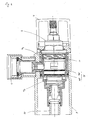
- a thermostatic mixing valve for the distribution of sanitary water comprises a body 1, which is provided with a cold water inlet port 2, an inlet port hot water 3 and an outlet 4 of the mixed water.
- This body 1 of generally cylindrical shape comprises, on the side of the cold water inlet port, a knob 5 for controlling the flow of mixed water operating a mechanism for adjusting this flow rate. and on the side of the hot water inlet a mixing knob 6 to regulate the temperature of the mixed water.
- This mixing valve 6 belongs to a cartridge 7 disposed in this mixing valve and known in itself.
- This cartridge 7 comprises, in particular, a thermostatic element 8, a shuttle 9 or dispenser carriage and a seat 10.
- the thermostatic element 8 is known in itself and controlled by the mixer knob 6.
- the shuttle 9 is, according to the present invention, made of two elements 9a and 9b which are interconnected, for example by threading, and which each comprise a shoulder 11a and 11b.
- the shoulders 11a and 11b face each other forming a double valve: in this case, the shoulder 11 is the valve for the hot water and the shoulder 11 b the valve for cold water.
- the seat 10 which is attached, of the double-sided type, and which is fixed to the outside of the shuttle 9.
- the double-sided seat 10 thus has a first face 10b vis-à-vis the cold water valve 11b and a second face 10a vis-à-vis the hot water valve 11a.
- This seat 10 is held in the body 1 of the mixer tap by the head body 13 of the mixer mechanism and preferably via a spacer 14 which extends the head body 13 and bears on the second face 10a of the seat 10.
- the seat 10 can be maintained cold water inlet side by a socket 15 through which the mixed water is discharged towards the outlet port 4.
- This sleeve 15 is supported on a shoulder 16 carried by the body 1 of the mixing valve; it is prolonged in the body 1 by a pipe 18.
- the double-sided seat which is ring-shaped, can be made of elastomer reinforced by a rigid core which prevents such a seat from coming out of its seat.
- the fact of making this seat 10 elastomer has the advantage of ensuring a perfect seal between the second face 10a thereof and the valve 11a in case of a high pressure drop or a water cutoff cold.
- the thermostatic element 8 passes through the shuttle 9 along its longitudinal axis, which is also that of the body 1. It may comprise a thread receiving a counter-nut 19 which makes it possible to make the two elements 9a and 9b of the shuttle 9 integral with each other. .
- the cartridge 7, as described above, can be contained in a jacket 17 made of a thermal insulating material and then constituting the sleeve 15; it is therefore located between the body 1 of the mixer tap and all the control elements already described: this avoids a rise in temperature of the body 1 of the mixing valve on the hot water inlet side.
- this liner 17 serves as a bearing face for the seat 10.
- this liner 17 is extended inside the body 1 by the mixed water pipe 18 up to the outlet 4 of mixed water which is located towards the other end of this tap
- the pipe 18 made of thermal insulating material is completely immersed in cold water, thus crossing axially through the cold water circuit in the body 1. Thus only the cold water is in contact with the casing of the body 1.
- this duct 18 constitutes the seat 18a for the mechanism regulating the flow of water mixed by the button 5.
- the cold water fills most of the main body 1: the pipe 18 for the evacuation of the mixed water bathes therefore in cold water.
Landscapes
- Engineering & Computer Science (AREA)
- General Engineering & Computer Science (AREA)
- Mechanical Engineering (AREA)
- Physics & Mathematics (AREA)
- General Physics & Mathematics (AREA)
- Automation & Control Theory (AREA)
- Temperature-Responsive Valves (AREA)
- Multiple-Way Valves (AREA)
- Grinding-Machine Dressing And Accessory Apparatuses (AREA)
Abstract
Description
- La présente invention concerne un robinet mitigeur thermostatique pour la distribution d'eau mitigée sanitaire.
- On connaît des robinets mitigeurs sanitaires tel que celui décrit dans le document
EP-943.740-A - Ce chariot distributeur, ou navette, de forme cylindrique, comme par exemple celui-ci décrit dans le document
EP-759.522-A - Inversement, quand l'eau mitigée se refroidit, l'élément thermostatique se rétracte entraînant par là-même un déplacement du chariot distributeur provoquant une réduction de la section de passage pour l'eau froide et une augmentation de celle pour l'eau chaude.
- Mais, selon les documents antérieurs ci-dessus, quand la pression d'eau froide baisse, la pression d'eau chaude, lui devenant supérieure, pousse le chariot distributeur dans le sens qui a tendance à réduire la section de passage pour l'eau froide : ceci accentue le déséquilibre et l'augmentation de la température de l'eau mitigée. Seul l'élément thermostatique par sa dilatation peut corriger cette augmentation de température : la régulation de la température mitigée est donc moins bonne en cas de variation de pression de l'eau chaude ou de l'eau froide.
- Pour remédier à cet inconvénient, certains robinets mitigeurs comportent un élément thermostatique couplé avec un équilibreur de pression, tel que celui décrit dans le document
EP-569.437-A - Aussi, un des buts de la présente invention est-il de fournir un robinet mitigeur thermostatique pour eau sanitaire permettant de pallier les inconvénients ci-dessus.
- Un autre but de l'invention est de fournir un tel robinet qui permet d'éviter à un utilisateur de se brûler par contact avec le corps du robinet, même dans le cas où la température de l'eau mitigée deviendrait élevée.
- Ces buts, ainsi que d'autres qui apparaîtront par la suite, sont atteints par un robinet mitigeur pour la distribution d'eau mitigée sanitaire comprenant, d'une part, un corps de forme générale cylindrique, qui est muni d'un orifice d'admission d'eau froide, d'un orifice d'admission d'eau chaude et d'un orifice de sortie de l'eau mitigée, comportant, du côté de l'orifice d'admission d'eau froide, un bouton pour commander le débit d'eau mitigée actionnant un mécanisme pour régler ce débit, et, du côté de l'orifice d'admission d'eau chaude, un bouton mitigeur pour réguler la température d'eau mitigée faisant partie d'une cartouche comprenant notamment un élément thermostatique, une navette et un siège, et, d'autre part, une conduite reliant cette cartouche à l'orifice de sortie de l'eau mitigée, lequel robinet est, selon la présente invention, caractérisé par le fait que la navette est constituée de deux éléments qui sont reliés entre eux et qui comportent chacun un épaulement se faisant face et constituant chacun un clapet, l'un pour l'eau chaude et l'autre pour l'eau froide, et que le siège rapporté double face, qui est rendu fixe à l'extérieur de cette navette, est disposé entre ces épaulements.
- Avantageusement, le siège rapporté double face présente une première face vis-à-vis du clapet d'eau froide et une seconde face vis-à-vis du clapet d'eau chaude.
- De préférence, le siège rapporté double face est maintenu par une entretoise prolongeant le corps de tête et venant en appui sur la seconde face du siège.
- Avantageusement, le siège est maintenu, côté arrivée eau froide, par une douille par laquelle l'eau mitigée est évacuée en direction de l'orifice de sortie.
- Selon un mode de réalisation préféré de la présente invention, le siège rapporté double face est en forme d'anneau et est réalisé en élastomère renforcé par une âme rigide.
- Avantageusement, l'élément thermostatique traverse la navette selon son axe longitudinal, qui est aussi celui du corps.
- De préférence, la cartouche est contenue dans une chemise en un matériau isolant thermique qui est située entre le corps du robinet mitigeur et l'ensemble des éléments de régulation.
- Avantageusement, la douille de sortie de l'eau mitigée se prolonge dans l'axe du corps du robinet par une conduite qui est coaxiale à ce corps, et totalement entourée par la conduite d'eau froide : ainsi, seule la conduite d'eau froide est en contact avec la paroi extérieure du corps du robinet mitigeur.
- De préférence, la conduite d'eau mitigée est le siège du mécanisme de réglage de débit de l'eau mitigée actionné par le bouton pour commander le débit d'eau mitigée.
- Selon un mode de réalisation préféré, les deux éléments de la navette sont rendus solidaires par vissage d'un écrou sur l'élément thermostatique.
- La description qui va suivre et qui ne présente aucun caractère limitatif, doit être lue en regard des figures annexées, parmi lesquelles :
- la
figure 1 est une vue en coupe transversale d'un robinet mitigeur thermostatique pour eau sanitaire selon la présente invention ; - la
figure 2 est une vue en coupe de ce robinet selon la ligne II-II de lafigure 1 ; - la
figure 3 est une vue grossie de la partie A du robinet représenté à lafigure 1 et comportant un isolant thermique ; - la
figure 4 est une vue extérieure du sous-ensemble ou cartouche 7 ; - la
figure 5 est une vue en coupé de la cartouche selon la ligne V-V de lafigure 4 ; et, - la
figure 6 est une vue grossie du détail B de lafigure 5 . - Ainsi qu'on peut le voir sur ces figures, un robinet mitigeur thermostatique pour la distribution d'eau sanitaire comprend un corps 1, qui est muni d'un orifice d'admission d'eau froide 2, d'un orifice d'admission d'eau chaude 3 et d'un orifice de sortie 4 de l'eau mitigée.
- Ce corps 1 de forme générale cylindrique, selon le présent exemple de réalisation, comporte, du côté de l'orifice d'admission d'eau froide, un bouton 5 pour commander le débit d'eau mitigée actionnant un mécanisme de réglage de ce débit, et du côté de l'orifice d'admission d'eau chaude un bouton mitigeur 6 pour réguler la température de l'eau mitigée. Ce bouton mitigeur 6 appartient à une cartouche 7 disposée dans ce robinet mitigeur et connue en elle-même.
- Cette cartouche 7 comprend, en particulier, un élément thermostatique 8, une navette 9 ou chariot distributeur et un siège 10.
- L'élément thermostatique 8 est connu en lui-même et commandé par le bouton mitigeur 6.
- Le navette 9 est, selon la présente invention, constituée de deux éléments 9a et 9b qui sont reliés entre eux, par exemple par filetage, et qui comportent chacun un épaulement 11 a et 11 b. Les épaulements 11 a et 11 b se font face constituant un double clapet : dans le cas présent, l'épaulement 11 a constitue le clapet pour l'eau chaude et l'épaulement 11 b le clapet pour l'eau froide.
- Entre les deux clapets 11a et 11 b, donc dans la gorge 12, est disposé le siège 10 qui est rapporté, du genre à double face, et qui est rendu fixe à l'extérieur de la navette 9.
- Le siège 10 rapporté double face présente donc une première face 10b vis-à-vis du clapet eau froide 11b et une seconde face 10a vis-à-vis du clapet eau chaude 11a. Ce siège 10 est maintenu dans le corps 1 du robinet mitigeur par le corps de tête 13 du mécanisme mitigeur et préférablement par l'intermédiaire d'une entretoise 14 qui prolonge ce corps de tête 13 et vient en appui sur la seconde face 10a du siège 10.
- Le siège 10 peut être maintenu côté arrivée eau froide par une douille 15 par laquelle l'eau mitigée est évacuée en direction de l'orifice de sortie 4. Cette douille 15 prend appui sur un épaulement 16 porté par le corps 1 du robinet mitigeur; elle se prolonge dans le corps 1 par une conduite 18.
- Le siège 10 rapporté double face, qui est en forme d'anneau, peut être réalisé en élastomère renforcé par une âme rigide qui empêche un tel siège de sortir de son logement. De plus, le fait de réaliser ce siège 10 en élastomère a pour avantage de garantir une étanchéité parfaite entre la seconde face 10a de celui-ci et le clapet 11a en cas d'une forte chute de pression ou d'une coupure d'eau froide.
- L'élément thermostatique 8 traverse la navette 9 selon son axe longitudinal, qui est aussi celui du corps 1. Il peut comporter un filetage recevant un contre-écrou 19 qui permet de rendre solidaire entre eux les deux éléments 9a et 9b de la navette 9.
- La cartouche 7, telle que décrite ci-dessus, peut être contenue dans une chemise 17 en un matériau isolant thermique et constituant alors la douille 15 ; elle est donc située entre le corps 1 du robinet mitigeur et l'ensemble des éléments de régulation déjà décrits : ceci permet d'éviter une montée en température du corps 1 du robinet mitigeur côté arrivée eau chaude.
- Selon une variante de réalisation, la face intérieure de cette chemise 17 sert de face d'appui pour le siège 10. De plus, cette chemise 17 est prolongée à l'intérieur du corps 1 par la conduite 18 d'eau mitigée jusqu'à l'orifice de sortie 4 d'eau mitigée qui est située vers l'autre extrémité de ce robinet
- La conduite 18 en matériau isolant thermique baigne entièrement dans l'eau froide, traversant ainsi de part en part axialement le circuit d'eau froide dans le corps 1. Ainsi seule l'eau froide est en contact avec l'enveloppe du corps 1. De plus, cette conduite 18 constitue le siège 18a pour le mécanisme réglant le débit d'eau mitigée par le bouton 5.
- Ainsi que l'aura compris l'homme du métier, dans le robinet mitigeur thermostatique selon la présente invention, l'eau froide remplit la plus grande partie du corps principal 1 : la conduite 18 pour l'évacuation de l'eau mitigée baigne donc dans de l'eau froide.
Claims (10)
- Robinet mitigeur thermostatique pour la distribution d'eau mitigée sanitaire comprenant, d'une part, un corps (1) de forme générale cylindrique, qui est muni d'un orifice d'admission d'eau froide (2), d'un orifice d'admission d'eau chaude (3) et d'un orifice de sortie (4) de l'eau mitigée, comportant du côté de l'orifice d'admission d'eau froide, un bouton (5) pour commander le débit d'eau mitigée actionnant un mécanisme de réglage dudit débit, et, du côté de l'orifice d'admission d'eau chaude (3), un bouton mitigeur (6) pour réguler la température d'eau mitigée, et, dans lequel est disposée une cartouche (7) comprenant notamment un élément thermostatique (8), une navette (9) et un siège (10), et, d'autre part, une conduite reliant ladite cartouche (7) audit orifice de sortie (4) d'eau mitigée, caractérisé par le fait que la navette (9) est constituée de deux éléments (9a) et (9b) qui sont reliés entre eux et comportent chacun un épaulement (11a, 11b) se faisant face et constituant chacun un clapet, l'un (11a) pour l'eau chaude et l'autre (11b) pour l'eau froide, et que ledit siège (10) rapporté double face, qui est rendu fixe à l'extérieur de ladite navette (9), est disposé entre lesdits épaulements (11a, 11b).
- Robinet selon la revendication 1, caractérisé par le fait que le siège (10) rapporté double face présente une première face 10b clapet d'eau froide (11b) et une seconde face (10a) vis-à-vis du clapet d'eau chaude (11a).
- Robinet selon la revendication 1, caractérisé par le fait que le siège (10) est maintenu par une entretoise (14) prolongeant le corps de tête (13) et venant en appui sur la seconde face (10a) du siège (10).
- Robinet selon la revendication 1, caractérisé par le fait que le siège (10) est maintenu, côté arrivée eau froide, par une douille (15 ou 17) par laquelle l'eau mitigée est évacuée en direction de l'orifice de sortie (4).
- Robinet selon la revendication 1, caractérisé par le fait que le siège (10) rapporté double face est en forme d'anneau et est réalisé en élastomère renforcé par une âme rigide.
- Robinet selon la revendication 1, caractérisé par le fait que l'élément thermostatique (8) traverse la navette (9) selon son axe longitudinal, qui est aussi celui du corps (1).
- Robinet selon la revendication 1, caractérisé par le fait que la cartouche (7) est contenue dans une chemise (17) en un matériau isolant thermique qui est située entre le corps (1) dudit robinet mitigeur et l'ensemble des éléments de régulation.
- Robinet selon la revendication 4, caractérisé par le fait que la douille (15 ou 17) de sortie de l'eau mitigée se prolonge dans l'axe dudit corps (1) par une conduite (18), lesdites douille (15 ou 17) et conduite (18) étant totalement entourées par la conduite d'eau froide.
- Robinet selon la revendication 8, caractérisé par le fait que la conduite (18) d'eau mitigée est le siège (18a) du mécanisme de réglage du débit d'eau mitigée.
- Robinet selon la revendication 6, caractérisé par le fait que les deux éléments (9a) et (9b) de la navette (9) sont rendus solidaires par vissage d'un écrou (19) sur l'élément thermostatique (8).
Applications Claiming Priority (1)
| Application Number | Priority Date | Filing Date | Title |
|---|---|---|---|
| FR0803823A FR2933470B1 (fr) | 2008-07-04 | 2008-07-04 | Robinet mitigeur thermostatique |
Publications (2)
| Publication Number | Publication Date |
|---|---|
| EP2141394A1 true EP2141394A1 (fr) | 2010-01-06 |
| EP2141394B1 EP2141394B1 (fr) | 2012-01-18 |
Family
ID=40418952
Family Applications (1)
| Application Number | Title | Priority Date | Filing Date |
|---|---|---|---|
| EP09290539A Active EP2141394B1 (fr) | 2008-07-04 | 2009-07-03 | Robinet mitigeur thermostatique |
Country Status (3)
| Country | Link |
|---|---|
| EP (1) | EP2141394B1 (fr) |
| AT (1) | ATE542075T1 (fr) |
| FR (1) | FR2933470B1 (fr) |
Cited By (10)
| Publication number | Priority date | Publication date | Assignee | Title |
|---|---|---|---|---|
| EP2557340A1 (fr) * | 2011-08-08 | 2013-02-13 | Delabie | Mitigeur thermostatique monocommande à ouverture prioritaire en eau froide puis pour la distribution d'eau sanitaire à une température donnée |
| CN103307332A (zh) * | 2013-06-08 | 2013-09-18 | 本科电器有限公司 | 一种表面防烫恒温龙头壳体及其龙头 |
| CN103322261A (zh) * | 2013-06-27 | 2013-09-25 | 梁业浓 | 一种面盆龙头 |
| ITMI20130584A1 (it) * | 2013-04-11 | 2014-10-12 | Carlo Nobili S P A Rubinetterie | Miscelatore termostatico esterno, particolarmente per componenti igienico-sanitari, ad elevata sicurezza contro il pericolo di scottature da contatto. |
| FR3013417A1 (fr) * | 2013-11-18 | 2015-05-22 | Delabie | Robinet mitigeur thermostatique a corps froid |
| DE102015002569A1 (de) * | 2015-03-02 | 2016-09-08 | Grohe Ag | Sanitärarmatur |
| EP3296471A1 (fr) * | 2016-09-20 | 2018-03-21 | Ideal Standard International BVBA | Robinet mélangeur thermostatique avec élément de tuyau |
| CN113294579A (zh) * | 2021-06-17 | 2021-08-24 | 鹏威(厦门)工业有限公司 | 一种水路切换堵头以及一种恒温反向进水切换结构 |
| EP3929364A1 (fr) * | 2020-06-26 | 2021-12-29 | Grohe AG | Armature de mélangeur thermostatique et son procédé de fabrication |
| WO2022189441A1 (fr) * | 2021-03-12 | 2022-09-15 | Grohe Ag | Robinet mélangeur thermostatique et son procédé de fabrication |
Citations (9)
| Publication number | Priority date | Publication date | Assignee | Title |
|---|---|---|---|---|
| GB2139324A (en) * | 1983-03-04 | 1984-11-07 | Kitamura Gokin Seisakusho | Fixture for thermostatically mixing hot and cold water |
| EP0187378A2 (fr) * | 1985-01-02 | 1986-07-16 | Oras Oy | Soupape thermostatique |
| US4610393A (en) * | 1984-03-16 | 1986-09-09 | Kugler, Fonderie Et Robinetterie S.A. | Cold and hot water mixer tap with ceramic plates controlled by means of a thermostat |
| DE4116954A1 (de) * | 1990-06-07 | 1991-12-12 | Grohe Armaturen Friedrich | Mischbatterie |
| EP0569437A1 (fr) | 1991-02-01 | 1993-11-18 | Mattsson Ab F M | Systeme de regulation pour ensemble mitigeur, et tiroir a pistons. |
| EP0759522A1 (fr) | 1995-08-22 | 1997-02-26 | O.M.B.G. S.r.l. | Mitigeur thermostatique automatique |
| US5779139A (en) * | 1995-12-20 | 1998-07-14 | Ntc Kogyo Kabushiki Kaisha | Automatic water combination faucet |
| EP0943740A2 (fr) | 1998-03-16 | 1999-09-22 | Hansa Metallwerke Ag | Mitigeur sanitaire |
| US6575377B1 (en) * | 2002-03-01 | 2003-06-10 | Watts Regulator Co. | Mixing valve |
-
2008
- 2008-07-04 FR FR0803823A patent/FR2933470B1/fr not_active Expired - Fee Related
-
2009
- 2009-07-03 EP EP09290539A patent/EP2141394B1/fr active Active
- 2009-07-03 AT AT09290539T patent/ATE542075T1/de active
Patent Citations (9)
| Publication number | Priority date | Publication date | Assignee | Title |
|---|---|---|---|---|
| GB2139324A (en) * | 1983-03-04 | 1984-11-07 | Kitamura Gokin Seisakusho | Fixture for thermostatically mixing hot and cold water |
| US4610393A (en) * | 1984-03-16 | 1986-09-09 | Kugler, Fonderie Et Robinetterie S.A. | Cold and hot water mixer tap with ceramic plates controlled by means of a thermostat |
| EP0187378A2 (fr) * | 1985-01-02 | 1986-07-16 | Oras Oy | Soupape thermostatique |
| DE4116954A1 (de) * | 1990-06-07 | 1991-12-12 | Grohe Armaturen Friedrich | Mischbatterie |
| EP0569437A1 (fr) | 1991-02-01 | 1993-11-18 | Mattsson Ab F M | Systeme de regulation pour ensemble mitigeur, et tiroir a pistons. |
| EP0759522A1 (fr) | 1995-08-22 | 1997-02-26 | O.M.B.G. S.r.l. | Mitigeur thermostatique automatique |
| US5779139A (en) * | 1995-12-20 | 1998-07-14 | Ntc Kogyo Kabushiki Kaisha | Automatic water combination faucet |
| EP0943740A2 (fr) | 1998-03-16 | 1999-09-22 | Hansa Metallwerke Ag | Mitigeur sanitaire |
| US6575377B1 (en) * | 2002-03-01 | 2003-06-10 | Watts Regulator Co. | Mixing valve |
Cited By (17)
| Publication number | Priority date | Publication date | Assignee | Title |
|---|---|---|---|---|
| FR2978997A1 (fr) * | 2011-08-08 | 2013-02-15 | Delabie | Mitigeur thermostatique monocommande a ouverture prioritaire en eau froide puis pour la distribution d'eau sanitaire a une temperature donnee |
| EP2557340A1 (fr) * | 2011-08-08 | 2013-02-13 | Delabie | Mitigeur thermostatique monocommande à ouverture prioritaire en eau froide puis pour la distribution d'eau sanitaire à une température donnée |
| ITMI20130584A1 (it) * | 2013-04-11 | 2014-10-12 | Carlo Nobili S P A Rubinetterie | Miscelatore termostatico esterno, particolarmente per componenti igienico-sanitari, ad elevata sicurezza contro il pericolo di scottature da contatto. |
| EP2789885A1 (fr) * | 2013-04-11 | 2014-10-15 | Carlo Nobili S.p.A. Rubinetterie | Mélangeur thermostatique externe, en particulier pour des éléments hygiéno-sanitaires, avec une sécurité élevée contre le risque de brûlures de contact |
| CN103307332A (zh) * | 2013-06-08 | 2013-09-18 | 本科电器有限公司 | 一种表面防烫恒温龙头壳体及其龙头 |
| CN103322261A (zh) * | 2013-06-27 | 2013-09-25 | 梁业浓 | 一种面盆龙头 |
| GB2523624B (en) * | 2013-11-18 | 2020-04-22 | Delabie | A thermostatic mixer tap |
| FR3013417A1 (fr) * | 2013-11-18 | 2015-05-22 | Delabie | Robinet mitigeur thermostatique a corps froid |
| GB2523624A (en) * | 2013-11-18 | 2015-09-02 | Delabie | A thermostatic mixer tap |
| DE102014116399B4 (de) | 2013-11-18 | 2023-08-03 | Delabie | Thermostatischer Mischwasserhahn mit kaltem Körper |
| BE1025327B1 (fr) * | 2013-11-18 | 2019-01-28 | Delabie | Robinet mitigeur thermostatique a corps froid |
| DE102015002569A1 (de) * | 2015-03-02 | 2016-09-08 | Grohe Ag | Sanitärarmatur |
| EP3296471A1 (fr) * | 2016-09-20 | 2018-03-21 | Ideal Standard International BVBA | Robinet mélangeur thermostatique avec élément de tuyau |
| EP3929364A1 (fr) * | 2020-06-26 | 2021-12-29 | Grohe AG | Armature de mélangeur thermostatique et son procédé de fabrication |
| WO2022189441A1 (fr) * | 2021-03-12 | 2022-09-15 | Grohe Ag | Robinet mélangeur thermostatique et son procédé de fabrication |
| CN116670362A (zh) * | 2021-03-12 | 2023-08-29 | 高仪股份公司 | 恒温混合器配件及其制造方法 |
| CN113294579A (zh) * | 2021-06-17 | 2021-08-24 | 鹏威(厦门)工业有限公司 | 一种水路切换堵头以及一种恒温反向进水切换结构 |
Also Published As
| Publication number | Publication date |
|---|---|
| ATE542075T1 (de) | 2012-02-15 |
| FR2933470A1 (fr) | 2010-01-08 |
| FR2933470B1 (fr) | 2013-05-17 |
| EP2141394B1 (fr) | 2012-01-18 |
Similar Documents
| Publication | Publication Date | Title |
|---|---|---|
| EP2141394B1 (fr) | Robinet mitigeur thermostatique | |
| EP2047348B1 (fr) | Cartouche thermostatique a commandes de température et de débit concentriques, et robinet mitigeur équipé d'une telle cartouche | |
| EP0936524B1 (fr) | Cartouche de sécurité pour mitigeur thermostatique | |
| FR2940397A1 (fr) | Cartouche thermostatique monocommande et robinet mitigeur comportant une telle cartouche | |
| EP0258129A1 (fr) | Perfectionnements aux dispositifs mélangeurs thermostatiques, en particulier pour la distribution d'eau | |
| FR3011646A1 (fr) | Cartouche thermostatique monocommande | |
| WO2017097757A1 (fr) | Cartouche monocommande thermostatique et robinet mitigeur muni d'une telle cartouche | |
| EP1048997A1 (fr) | Cartouche de robinet mitigeur à limitation de température | |
| FR3055711B1 (fr) | Cartouche thermostatique | |
| WO2005103853A1 (fr) | Cartouche thermostatique de regulation de fluides chaud et froid a melanger, ainsi que robinet | |
| FR2712100A1 (fr) | Dispositif de mélange thermostatique. | |
| CH658110A5 (fr) | Dispositif de melange thermostatique d'eau chaude et d'eau froide. | |
| EP3488311B1 (fr) | Unité de mélange et robinet mitigeur comprenant une telle unité de mélange | |
| FR3050510A1 (fr) | Unite de melange et robinet mitigeur comprenant une telle unite de melange | |
| EP2557340B1 (fr) | Mitigeur thermostatique monocommande à ouverture prioritaire en eau froide puis pour la distribution d'eau sanitaire à une température donnée | |
| FR3071329B1 (fr) | Cartouche pour un robinet mitigeur | |
| EP2580506B1 (fr) | Dispositif de fermeture automatique temporisée | |
| JP5937930B2 (ja) | フロート式スチームトラップ | |
| JP4681945B2 (ja) | 湯水混合栓 | |
| JP5960018B2 (ja) | フロート式スチームトラップ | |
| WO2020115199A1 (fr) | Cartouche thermostatique pour robinet mitigeur | |
| JP2007032271A (ja) | 水栓装置 | |
| FR2734620A1 (fr) | Cartouche pour robinets domestiques thermostates munis d'une monocommande pour les reglages temperature et debit | |
| JP6027896B2 (ja) | フロート式スチームトラップ | |
| EP1695166B1 (fr) | Cartouche thermostatique avec clapets anti-retour integres et installation la comportant |
Legal Events
| Date | Code | Title | Description |
|---|---|---|---|
| PUAI | Public reference made under article 153(3) epc to a published international application that has entered the european phase |
Free format text: ORIGINAL CODE: 0009012 |
|
| AK | Designated contracting states |
Kind code of ref document: A1 Designated state(s): AT BE BG CH CY CZ DE DK EE ES FI FR GB GR HR HU IE IS IT LI LT LU LV MC MK MT NL NO PL PT RO SE SI SK SM TR |
|
| 17P | Request for examination filed |
Effective date: 20100224 |
|
| 17Q | First examination report despatched |
Effective date: 20100325 |
|
| GRAP | Despatch of communication of intention to grant a patent |
Free format text: ORIGINAL CODE: EPIDOSNIGR1 |
|
| GRAS | Grant fee paid |
Free format text: ORIGINAL CODE: EPIDOSNIGR3 |
|
| GRAA | (expected) grant |
Free format text: ORIGINAL CODE: 0009210 |
|
| RAP1 | Party data changed (applicant data changed or rights of an application transferred) |
Owner name: DELABIE |
|
| AK | Designated contracting states |
Kind code of ref document: B1 Designated state(s): AT BE BG CH CY CZ DE DK EE ES FI FR GB GR HR HU IE IS IT LI LT LU LV MC MK MT NL NO PL PT RO SE SI SK SM TR |
|
| REG | Reference to a national code |
Ref country code: GB Ref legal event code: FG4D Free format text: NOT ENGLISH |
|
| REG | Reference to a national code |
Ref country code: CH Ref legal event code: EP |
|
| REG | Reference to a national code |
Ref country code: AT Ref legal event code: REF Ref document number: 542075 Country of ref document: AT Kind code of ref document: T Effective date: 20120215 Ref country code: IE Ref legal event code: FG4D Free format text: LANGUAGE OF EP DOCUMENT: FRENCH Ref country code: NL Ref legal event code: T3 |
|
| REG | Reference to a national code |
Ref country code: DE Ref legal event code: R096 Ref document number: 602009004739 Country of ref document: DE Effective date: 20120315 |
|
| LTIE | Lt: invalidation of european patent or patent extension |
Effective date: 20120118 |
|
| PG25 | Lapsed in a contracting state [announced via postgrant information from national office to epo] |
Ref country code: HR Free format text: LAPSE BECAUSE OF FAILURE TO SUBMIT A TRANSLATION OF THE DESCRIPTION OR TO PAY THE FEE WITHIN THE PRESCRIBED TIME-LIMIT Effective date: 20120118 Ref country code: BG Free format text: LAPSE BECAUSE OF FAILURE TO SUBMIT A TRANSLATION OF THE DESCRIPTION OR TO PAY THE FEE WITHIN THE PRESCRIBED TIME-LIMIT Effective date: 20120418 Ref country code: IS Free format text: LAPSE BECAUSE OF FAILURE TO SUBMIT A TRANSLATION OF THE DESCRIPTION OR TO PAY THE FEE WITHIN THE PRESCRIBED TIME-LIMIT Effective date: 20120518 Ref country code: LT Free format text: LAPSE BECAUSE OF FAILURE TO SUBMIT A TRANSLATION OF THE DESCRIPTION OR TO PAY THE FEE WITHIN THE PRESCRIBED TIME-LIMIT Effective date: 20120118 Ref country code: NO Free format text: LAPSE BECAUSE OF FAILURE TO SUBMIT A TRANSLATION OF THE DESCRIPTION OR TO PAY THE FEE WITHIN THE PRESCRIBED TIME-LIMIT Effective date: 20120418 |
|
| REG | Reference to a national code |
Ref country code: IE Ref legal event code: FD4D |
|
| PG25 | Lapsed in a contracting state [announced via postgrant information from national office to epo] |
Ref country code: FI Free format text: LAPSE BECAUSE OF FAILURE TO SUBMIT A TRANSLATION OF THE DESCRIPTION OR TO PAY THE FEE WITHIN THE PRESCRIBED TIME-LIMIT Effective date: 20120118 Ref country code: PL Free format text: LAPSE BECAUSE OF FAILURE TO SUBMIT A TRANSLATION OF THE DESCRIPTION OR TO PAY THE FEE WITHIN THE PRESCRIBED TIME-LIMIT Effective date: 20120118 Ref country code: LV Free format text: LAPSE BECAUSE OF FAILURE TO SUBMIT A TRANSLATION OF THE DESCRIPTION OR TO PAY THE FEE WITHIN THE PRESCRIBED TIME-LIMIT Effective date: 20120118 Ref country code: PT Free format text: LAPSE BECAUSE OF FAILURE TO SUBMIT A TRANSLATION OF THE DESCRIPTION OR TO PAY THE FEE WITHIN THE PRESCRIBED TIME-LIMIT Effective date: 20120518 Ref country code: GR Free format text: LAPSE BECAUSE OF FAILURE TO SUBMIT A TRANSLATION OF THE DESCRIPTION OR TO PAY THE FEE WITHIN THE PRESCRIBED TIME-LIMIT Effective date: 20120419 |
|
| PGFP | Annual fee paid to national office [announced via postgrant information from national office to epo] |
Ref country code: LU Payment date: 20120720 Year of fee payment: 4 |
|
| REG | Reference to a national code |
Ref country code: AT Ref legal event code: MK05 Ref document number: 542075 Country of ref document: AT Kind code of ref document: T Effective date: 20120118 |
|
| PG25 | Lapsed in a contracting state [announced via postgrant information from national office to epo] |
Ref country code: CY Free format text: LAPSE BECAUSE OF FAILURE TO SUBMIT A TRANSLATION OF THE DESCRIPTION OR TO PAY THE FEE WITHIN THE PRESCRIBED TIME-LIMIT Effective date: 20120118 |
|
| PG25 | Lapsed in a contracting state [announced via postgrant information from national office to epo] |
Ref country code: RO Free format text: LAPSE BECAUSE OF FAILURE TO SUBMIT A TRANSLATION OF THE DESCRIPTION OR TO PAY THE FEE WITHIN THE PRESCRIBED TIME-LIMIT Effective date: 20120118 Ref country code: DK Free format text: LAPSE BECAUSE OF FAILURE TO SUBMIT A TRANSLATION OF THE DESCRIPTION OR TO PAY THE FEE WITHIN THE PRESCRIBED TIME-LIMIT Effective date: 20120118 Ref country code: EE Free format text: LAPSE BECAUSE OF FAILURE TO SUBMIT A TRANSLATION OF THE DESCRIPTION OR TO PAY THE FEE WITHIN THE PRESCRIBED TIME-LIMIT Effective date: 20120118 Ref country code: IE Free format text: LAPSE BECAUSE OF FAILURE TO SUBMIT A TRANSLATION OF THE DESCRIPTION OR TO PAY THE FEE WITHIN THE PRESCRIBED TIME-LIMIT Effective date: 20120118 Ref country code: SI Free format text: LAPSE BECAUSE OF FAILURE TO SUBMIT A TRANSLATION OF THE DESCRIPTION OR TO PAY THE FEE WITHIN THE PRESCRIBED TIME-LIMIT Effective date: 20120118 Ref country code: SE Free format text: LAPSE BECAUSE OF FAILURE TO SUBMIT A TRANSLATION OF THE DESCRIPTION OR TO PAY THE FEE WITHIN THE PRESCRIBED TIME-LIMIT Effective date: 20120118 Ref country code: CZ Free format text: LAPSE BECAUSE OF FAILURE TO SUBMIT A TRANSLATION OF THE DESCRIPTION OR TO PAY THE FEE WITHIN THE PRESCRIBED TIME-LIMIT Effective date: 20120118 |
|
| PLBE | No opposition filed within time limit |
Free format text: ORIGINAL CODE: 0009261 |
|
| STAA | Information on the status of an ep patent application or granted ep patent |
Free format text: STATUS: NO OPPOSITION FILED WITHIN TIME LIMIT |
|
| PG25 | Lapsed in a contracting state [announced via postgrant information from national office to epo] |
Ref country code: SK Free format text: LAPSE BECAUSE OF FAILURE TO SUBMIT A TRANSLATION OF THE DESCRIPTION OR TO PAY THE FEE WITHIN THE PRESCRIBED TIME-LIMIT Effective date: 20120118 Ref country code: IT Free format text: LAPSE BECAUSE OF FAILURE TO SUBMIT A TRANSLATION OF THE DESCRIPTION OR TO PAY THE FEE WITHIN THE PRESCRIBED TIME-LIMIT Effective date: 20120118 |
|
| 26N | No opposition filed |
Effective date: 20121019 |
|
| PG25 | Lapsed in a contracting state [announced via postgrant information from national office to epo] |
Ref country code: AT Free format text: LAPSE BECAUSE OF FAILURE TO SUBMIT A TRANSLATION OF THE DESCRIPTION OR TO PAY THE FEE WITHIN THE PRESCRIBED TIME-LIMIT Effective date: 20120118 |
|
| PGFP | Annual fee paid to national office [announced via postgrant information from national office to epo] |
Ref country code: NL Payment date: 20120719 Year of fee payment: 4 |
|
| REG | Reference to a national code |
Ref country code: DE Ref legal event code: R097 Ref document number: 602009004739 Country of ref document: DE Effective date: 20121019 |
|
| PG25 | Lapsed in a contracting state [announced via postgrant information from national office to epo] |
Ref country code: MC Free format text: LAPSE BECAUSE OF NON-PAYMENT OF DUE FEES Effective date: 20120731 Ref country code: MK Free format text: LAPSE BECAUSE OF FAILURE TO SUBMIT A TRANSLATION OF THE DESCRIPTION OR TO PAY THE FEE WITHIN THE PRESCRIBED TIME-LIMIT Effective date: 20120118 |
|
| PG25 | Lapsed in a contracting state [announced via postgrant information from national office to epo] |
Ref country code: ES Free format text: LAPSE BECAUSE OF FAILURE TO SUBMIT A TRANSLATION OF THE DESCRIPTION OR TO PAY THE FEE WITHIN THE PRESCRIBED TIME-LIMIT Effective date: 20120429 |
|
| PG25 | Lapsed in a contracting state [announced via postgrant information from national office to epo] |
Ref country code: MT Free format text: LAPSE BECAUSE OF FAILURE TO SUBMIT A TRANSLATION OF THE DESCRIPTION OR TO PAY THE FEE WITHIN THE PRESCRIBED TIME-LIMIT Effective date: 20120118 |
|
| REG | Reference to a national code |
Ref country code: NL Ref legal event code: V1 Effective date: 20140201 |
|
| REG | Reference to a national code |
Ref country code: CH Ref legal event code: PL |
|
| GBPC | Gb: european patent ceased through non-payment of renewal fee |
Effective date: 20130703 |
|
| PG25 | Lapsed in a contracting state [announced via postgrant information from national office to epo] |
Ref country code: NL Free format text: LAPSE BECAUSE OF NON-PAYMENT OF DUE FEES Effective date: 20140201 Ref country code: LI Free format text: LAPSE BECAUSE OF NON-PAYMENT OF DUE FEES Effective date: 20130731 Ref country code: CH Free format text: LAPSE BECAUSE OF NON-PAYMENT OF DUE FEES Effective date: 20130731 Ref country code: TR Free format text: LAPSE BECAUSE OF FAILURE TO SUBMIT A TRANSLATION OF THE DESCRIPTION OR TO PAY THE FEE WITHIN THE PRESCRIBED TIME-LIMIT Effective date: 20120118 Ref country code: GB Free format text: LAPSE BECAUSE OF NON-PAYMENT OF DUE FEES Effective date: 20130703 |
|
| PG25 | Lapsed in a contracting state [announced via postgrant information from national office to epo] |
Ref country code: SM Free format text: LAPSE BECAUSE OF FAILURE TO SUBMIT A TRANSLATION OF THE DESCRIPTION OR TO PAY THE FEE WITHIN THE PRESCRIBED TIME-LIMIT Effective date: 20120118 |
|
| PG25 | Lapsed in a contracting state [announced via postgrant information from national office to epo] |
Ref country code: HU Free format text: LAPSE BECAUSE OF FAILURE TO SUBMIT A TRANSLATION OF THE DESCRIPTION OR TO PAY THE FEE WITHIN THE PRESCRIBED TIME-LIMIT Effective date: 20090703 |
|
| REG | Reference to a national code |
Ref country code: FR Ref legal event code: PLFP Year of fee payment: 7 |
|
| PG25 | Lapsed in a contracting state [announced via postgrant information from national office to epo] |
Ref country code: LU Free format text: LAPSE BECAUSE OF NON-PAYMENT OF DUE FEES Effective date: 20130703 |
|
| REG | Reference to a national code |
Ref country code: FR Ref legal event code: PLFP Year of fee payment: 8 |
|
| PGFP | Annual fee paid to national office [announced via postgrant information from national office to epo] |
Ref country code: BE Payment date: 20160718 Year of fee payment: 8 |
|
| REG | Reference to a national code |
Ref country code: FR Ref legal event code: PLFP Year of fee payment: 9 |
|
| REG | Reference to a national code |
Ref country code: BE Ref legal event code: MM Effective date: 20170731 |
|
| REG | Reference to a national code |
Ref country code: FR Ref legal event code: PLFP Year of fee payment: 10 |
|
| PG25 | Lapsed in a contracting state [announced via postgrant information from national office to epo] |
Ref country code: BE Free format text: LAPSE BECAUSE OF NON-PAYMENT OF DUE FEES Effective date: 20170731 |
|
| PGFP | Annual fee paid to national office [announced via postgrant information from national office to epo] |
Ref country code: DE Payment date: 20250725 Year of fee payment: 17 |
|
| PGFP | Annual fee paid to national office [announced via postgrant information from national office to epo] |
Ref country code: FR Payment date: 20250715 Year of fee payment: 17 |