EP2141383A1 - Hydrodynamische Kopplungseinrichtung - Google Patents
Hydrodynamische Kopplungseinrichtung Download PDFInfo
- Publication number
- EP2141383A1 EP2141383A1 EP09164116A EP09164116A EP2141383A1 EP 2141383 A1 EP2141383 A1 EP 2141383A1 EP 09164116 A EP09164116 A EP 09164116A EP 09164116 A EP09164116 A EP 09164116A EP 2141383 A1 EP2141383 A1 EP 2141383A1
- Authority
- EP
- European Patent Office
- Prior art keywords
- spring
- damper
- main
- springs
- assembly
- Prior art date
- Legal status (The legal status is an assumption and is not a legal conclusion. Google has not performed a legal analysis and makes no representation as to the accuracy of the status listed.)
- Granted
Links
- 230000008878 coupling Effects 0.000 title claims description 17
- 238000010168 coupling process Methods 0.000 title claims description 17
- 238000005859 coupling reaction Methods 0.000 title claims description 17
- 230000007935 neutral effect Effects 0.000 claims description 10
- 230000005540 biological transmission Effects 0.000 claims description 7
- 230000002093 peripheral effect Effects 0.000 claims description 5
- 235000019589 hardness Nutrition 0.000 description 8
- 238000013016 damping Methods 0.000 description 4
- 230000000694 effects Effects 0.000 description 4
- 238000002485 combustion reaction Methods 0.000 description 2
- 238000006073 displacement reaction Methods 0.000 description 1
- 239000002184 metal Substances 0.000 description 1
- 230000010355 oscillation Effects 0.000 description 1
- 238000002360 preparation method Methods 0.000 description 1
Images


Classifications
-
- F—MECHANICAL ENGINEERING; LIGHTING; HEATING; WEAPONS; BLASTING
- F16—ENGINEERING ELEMENTS AND UNITS; GENERAL MEASURES FOR PRODUCING AND MAINTAINING EFFECTIVE FUNCTIONING OF MACHINES OR INSTALLATIONS; THERMAL INSULATION IN GENERAL
- F16H—GEARING
- F16H45/00—Combinations of fluid gearings for conveying rotary motion with couplings or clutches
- F16H45/02—Combinations of fluid gearings for conveying rotary motion with couplings or clutches with mechanical clutches for bridging a fluid gearing of the hydrokinetic type
-
- F—MECHANICAL ENGINEERING; LIGHTING; HEATING; WEAPONS; BLASTING
- F16—ENGINEERING ELEMENTS AND UNITS; GENERAL MEASURES FOR PRODUCING AND MAINTAINING EFFECTIVE FUNCTIONING OF MACHINES OR INSTALLATIONS; THERMAL INSULATION IN GENERAL
- F16F—SPRINGS; SHOCK-ABSORBERS; MEANS FOR DAMPING VIBRATION
- F16F15/00—Suppression of vibrations in systems; Means or arrangements for avoiding or reducing out-of-balance forces, e.g. due to motion
- F16F15/10—Suppression of vibrations in rotating systems by making use of members moving with the system
- F16F15/12—Suppression of vibrations in rotating systems by making use of members moving with the system using elastic members or friction-damping members, e.g. between a rotating shaft and a gyratory mass mounted thereon
- F16F15/121—Suppression of vibrations in rotating systems by making use of members moving with the system using elastic members or friction-damping members, e.g. between a rotating shaft and a gyratory mass mounted thereon using springs as elastic members, e.g. metallic springs
- F16F15/123—Wound springs
- F16F15/1232—Wound springs characterised by the spring mounting
- F16F15/12346—Set of springs, e.g. springs within springs
-
- F—MECHANICAL ENGINEERING; LIGHTING; HEATING; WEAPONS; BLASTING
- F16—ENGINEERING ELEMENTS AND UNITS; GENERAL MEASURES FOR PRODUCING AND MAINTAINING EFFECTIVE FUNCTIONING OF MACHINES OR INSTALLATIONS; THERMAL INSULATION IN GENERAL
- F16H—GEARING
- F16H45/00—Combinations of fluid gearings for conveying rotary motion with couplings or clutches
- F16H2045/007—Combinations of fluid gearings for conveying rotary motion with couplings or clutches comprising a damper between turbine of the fluid gearing and the mechanical gearing unit
-
- F—MECHANICAL ENGINEERING; LIGHTING; HEATING; WEAPONS; BLASTING
- F16—ENGINEERING ELEMENTS AND UNITS; GENERAL MEASURES FOR PRODUCING AND MAINTAINING EFFECTIVE FUNCTIONING OF MACHINES OR INSTALLATIONS; THERMAL INSULATION IN GENERAL
- F16H—GEARING
- F16H45/00—Combinations of fluid gearings for conveying rotary motion with couplings or clutches
- F16H45/02—Combinations of fluid gearings for conveying rotary motion with couplings or clutches with mechanical clutches for bridging a fluid gearing of the hydrokinetic type
- F16H2045/0221—Combinations of fluid gearings for conveying rotary motion with couplings or clutches with mechanical clutches for bridging a fluid gearing of the hydrokinetic type with damping means
- F16H2045/0247—Combinations of fluid gearings for conveying rotary motion with couplings or clutches with mechanical clutches for bridging a fluid gearing of the hydrokinetic type with damping means having a turbine with hydrodynamic damping means
Definitions
- the present invention relates to a hydrodynamic coupling device, in particular a hydrodynamic torque converter, comprising a housing which can be coupled to a drive shaft with an impeller and a turbine wheel which can be driven by the impeller and can be coupled to an output shaft in an interior of the housing, a bridging clutch for selectively coupling the housing to one An output member, and a damper assembly in the torque transmission path to the output member, the damper assembly comprising a first damper element and against the action of a damper spring assembly with respect to the first damper element about a rotation rotatable second damper element, wherein the damper spring assembly comprises a plurality of circumferentially distributed damper spring units and in assignment to each damper spring unit on the first damper element and the second damper element support portions for supporting the repetsend Schemee the Damper spring units are provided.
- Such hydrodynamic coupling devices are typically arranged in the drive train of a motor vehicle between the engine and transmission in order to enable a power transmission between the crankshaft of the engine and the input shaft of the transmission, even if they rotate at different speeds.
- the arranged in the hydrodynamic coupling device damper assembly is provided for damping torsional vibrations of the drive train.
- damper spring assembly of the damper assembly is very soft, so has a relatively small spring hardness.
- large amplitude torsional vibration has the problem that the damper assembly loses its damping effect when the damper elements are in abutment or the damper spring assembly is stalled.
- Damper springs present in the damper spring arrangement can then be compressed beyond their elastic range.
- a hydrodynamic coupling device in particular a hydrodynamic torque converter, comprising a housing which can be coupled to a drive shaft with an impeller and a turbine wheel which can be driven by the impeller and can be coupled to an output shaft in an interior of the housing, a lock-up clutch for the optional Coupling of the housing with a driven member and a damper assembly in the torque transmission path to the output member, the damper assembly comprising a first damper element and against the action of a damper spring assembly with respect to the first damper element a second damper element rotatable about an axis of rotation, wherein the damper spring assembly comprises a plurality of circumferentially distributed damper spring units and provided in association with each damper spring unit on the first damper element and the second damper element support portions for supporting the supposedsend Schemee the damper spring units, wherein at least one damper spring unit comprises at least one main spring and in association with at least one main spring comprises at least one additional spring, wherein the main spring
- the damper elements adopt a neutral relative rotational position with respect to each other. If a torque is exerted on the damper arrangement, the damper elements are rotated relative to one another from the neutral relative rotational position until the damper spring arrangement effects an equally large counteracting torque. In this case, as the torque applied to the damper assembly increases, the damper elements first assume a rotational angle with respect to each other in the first rotational angle range and subsequently in the second rotational angle range.
- the damper spring arrangement has a lower spring stiffness in the first rotation angle range than in the second rotation angle range in which at least one additional spring also acts.
- the spring stiffness of the damper spring assembly in the first rotation angle range can be adjusted with the spring hardness of the main springs on the low-frequency torsional vibrations to be damped.
- the spring hardness in the second rotation angle range is composed of the spring hardness the main springs and at least one additional spring together and can be adjusted by the choice of the spring rate of at least one additional spring such that even with large torque fluctuations a damping effect of the damper assembly remains.
- the nesting of main and auxiliary spring leads to the further advantage that no additional space within the damper assembly is consumed by the auxiliary spring. Thus, with the same stability, the spatial extent of the damper elements can be maintained.
- At least one auxiliary spring associated with a main spring is shorter than the main spring.
- the structural design of damper elements, which were designed for the use of at least one main spring, must not be changed.
- the support areas provided for the main spring on the damper elements can be used to support the recordssend Schemee associated with the main spring auxiliary spring.
- At least one additional spring associated with a main spring is at least as long as the main spring.
- the one main spring associated at least one additional spring may be disposed within the main spring. But it is also possible that a main spring associated additional spring surrounds the main spring.
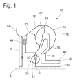
- a hydrodynamic torque converter to be provided in a powertrain of a vehicle, for example, between an internal combustion engine and a transmission input shaft is generally indicated at 10.
- the torque converter 10 comprises a housing arrangement 12 which is to be coupled via a coupling arrangement 14 provided thereon to a drive shaft, that is, for example, a crankshaft of an internal combustion engine, for common rotation about a rotation axis A.
- an impeller 16 is formed, which comprises a plurality of provided on an inner side of the converter housing 12 and circumferentially successive Pumpenradschaufeln 18.
- a turbine wheel 22 is provided in an inner space 20 of the converter housing 12. This comprises a plurality of circumferentially about the axis of rotation A successive turbine blades 24.
- the turbine 22 is coupled via a Torsionsschwingungsdämpferanssen 26 with an effective as a driven member turbine hub 28, which serves to receive a Gesreibeeingangswelle, not shown.
- the torsional vibration damper assembly 26 includes a damper member 30 rotatably connected to the turbine wheel 22 and a damper member 32 rotatably connected to the turbine hub 28, which are mutually opposed to the action of a damper spring assembly 34 are rotatable.
- stator blades 36 of a stator generally designated 38 Radially inwardly between the impeller blades 18 and the turbine blades 24 are stator blades 36 of a stator generally designated 38. This is rotatably supported on a support hollow shaft 40 in a direction about the axis of rotation A and surrounds the turbine hub 28.
- the support hollow shaft 40 surrounding a fixed to the converter housing 12 pump hub 42 is provided.
- the hydrodynamic torque converter 10 further includes a lock-up clutch, generally designated 44.
- This is the output side coupled, for example via the torsional vibration damper assembly 26 with the turbine hub 28 and rigidly connected to the turbine wheel 22.
- the lock-up clutch 44 is rigidly connected to the turbine hub 28 and coupled to the turbine wheel 22 via the torsional vibration damper assembly 26 or that the turbine wheel 22 is rigidly connected to the turbine hub 28 and coupled to the lock-up clutch 44 via the torsional vibration damper assembly 26.
- lock-up clutch 44 With the lock-up clutch 44, a direct mechanical coupling between the converter housing 12 and the turbine hub 28 can be realized.
- the lock-up clutch 44 can be engaged by the axial displacement of a piston element 46, which is arranged in the interior 20 of the converter housing 12.
- Fig. 2 shows the turbine wheel 22 and the damper assembly 26 of a hydrodynamic torque converter according to the invention in longitudinal section.
- the turbine wheel blades 24 are all arranged in a rounding of a turbine wheel shell 50 surrounding the axis A in the circumferential direction and connected thereto. Radially further inside, the turbine wheel shell 50 is connected via a plurality of bolts 52 with two cover disk elements surrounding the axle A. 54, 56 which are connected to each other by means of the bolts 52 and at the radially outer end by means of rivets 58.
- the cover plate elements 54 and 56 form the first damper element 30 of the damper assembly 26. They are supported on their inner peripheries 60, 62 on the turbine hub 28 and rotatably supported there with respect to the turbine hub 28.
- a sheet metal part 64 can be seen, which is used as the output element in the Fig. 1 shown bridging clutch 44 is used and which is also rotatably connected by means of bolts 52 with the cover plate elements 54, 56.
- the damper assembly 26 includes, in addition to the cover plate members 54 and 56, a central disc 66 surrounding the axis A and a plurality of damper spring units 68 circumferentially surrounding the axis A, which form the damper spring assembly 34 of the damper assembly 26.
- the central disk 66 forms the second damper element 32 of the damper assembly 26 and is rotatably connected in its inner peripheral region with the turbine hub 28 or optionally formed integrally.
- the bolts 52, which connect the cover disk elements 54, 56 are guided through openings 70 of the central disk 66, so that the central disk 66 and the cover disk elements 54, 56 with respect to each other about the axis A can be rotated by an angle of rotation, by the length of the Openings 70 is determined, as further below Fig. 3 is explained.
- the in the Fig. 2 Damper spring unit 68 shown comprises an outer main spring 72 and an auxiliary spring 74 disposed within the main spring 72.
- FIG. 2 illustrates a plan view of the central disk 66 of the damper assembly 26 from FIG Fig. 2
- a plurality of main springs 72, 72a, 72b, 72c, 72d is circumferentially surrounding the axis A within the central disk 66 formed recordings arranged.
- the main springs 72, 72a, 72b, 72c, 72d are supported on support portions 76, 76a, 76b, 76c, 76d.
- the main spring 72 and the auxiliary spring 74 are nested. In this case, the additional spring 74 is disposed within the main spring 72.
- a first rotation angle range the relative rotation between the central disk 66 and the cover disk elements 54, 56 initially by increasing the torque acting on the damper assembly 26 continue until a support region of the cover disk elements 54, 56 comes into contact with a memorisend Scheme 78 of the auxiliary spring 74 .
- the additional spring 74 then acts on the damper assembly 26 as the relative rotation continues to progress Torque against.
- the bolts 52 engage a circumferential end of the openings 70 and the relative rotation angle between the central disk 66 and the cover disk elements 54, 56 can not be further increased.
- the spring stiffness of the damper assembly 26 is determined in the first rotation angle range from the parallel main springs 72, 72a, 72b, 72c and 72d, in the second rotation angle range from the parallel main springs 72, 72a, 72b, 72c, 72d together with the auxiliary spring 74th
- FIG. 12 illustrates a plan view of the center disk 66 of the damper assembly of a second embodiment of the hydrodynamic torque converter of FIG Fig. 2 in the axial direction, wherein in another damper spring unit 68c, a further auxiliary spring 74c is disposed within the main spring 72c.
- the auxiliary spring 74c is in the in Fig. 4 shown neutral relative rotational position shorter than the auxiliary spring 74.
- the effect of the damper spring assembly of the Fig. 4 is different from the one from the Fig. 3 only from the relative rotation angle at which a support region of the cover disk elements 54, 56 corresponding to the support region 76c of the central disk 66 comes into contact with the peripheral end region 78c of the additional spring 74c.
- the main springs 72, 72a, 72b, 72c, 72d and the additional springs 74, 74c counteract the torque exerted on the damper arrangement.
- the spring stiffness of the spring arrangement is then determined by the parallel-connected main springs 72, 72a, 72b, 72c, 72d and auxiliary springs 74, 74c.
- a damper arrangement for a hydrodynamic coupling device for a hydrodynamic coupling device according to the invention
- the different rotation angle ranges with different spring hardnesses of the damper spring arrangement were realized by springs of different lengths which are shorter than the main springs.
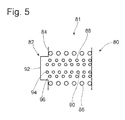
- Fig. 5 shows Fig. 5 a principle view of a damper spring unit 81 together with a support portion 80 of a damper element, such as a central disc, as shown in the Fig. 2 and a support portion 82 of another Damper element, for example, in the Fig. 2
- the damper spring unit 81 comprises a main spring 86 and two nested in the main spring 86 auxiliary springs 88, 90.
- the auxiliary spring 88 is disposed within the main spring 86, the additional spring 90 in turn within the auxiliary spring 88.
- the support portion 82 has a main support 86 supporting the main support portion 84 and the additional springs 88 and 90 supporting toastabstütz Scheme 92, which are offset from each other in the direction of the longitudinal axis of the springs.
- the spring stiffness of the damper spring unit 81 is composed of the spring hardness of the main spring 86 and the auxiliary spring 90 and a second rotation angle range begins. From the angle of rotation, in which also the additional spring 88 touches the additional support region 92 with its circumferential end region 96, all three springs 86, 88, 90 counteract the torque exerted on the damper arrangement.
- Additional stages with different spring hardnesses of the damper spring arrangement and / or flexible setting of the spring hardnesses in the rotation angle ranges can be achieved by further development of the invention in that three or more springs are used as a mainspring in one damper spring unit. and additional springs are nested, two or more damper spring units consist of two or more nested springs and / or at least two additional springs from different damper units in the neutral relative rotational position are the same length or different lengths or have different spring constants.
Landscapes
- Engineering & Computer Science (AREA)
- General Engineering & Computer Science (AREA)
- Mechanical Engineering (AREA)
- Physics & Mathematics (AREA)
- Acoustics & Sound (AREA)
- Aviation & Aerospace Engineering (AREA)
- Mechanical Operated Clutches (AREA)
Abstract
Description
- Die vorliegende Erfindung betrifft eine hydrodynamische Kopplungseinrichtung, insbesondere einen hydrodynamischen Drehmomentwandler, umfassend ein an eine Antriebswelle koppelbares Gehäuse mit einem Pumpenrad und ein in einem Innenraum des Gehäuses angeordnetes, vom Pumpenrad antreibbares mit einer Abtriebswelle koppelbares Turbinenrad, eine Überbrückungskupplung zur wahlweisen Kopplung des Gehäuses mit einem Abtriebsorgan, und eine Dämpferanordnung im Drehmomentübertragungsweg zu dem Abtriebsorgan, die Dämpferanordnung umfassend ein erstes Dämpferelement und ein gegen die Wirkung einer Dämpferfederanordnung bezüglich des ersten Dämpferelements um eine Drehachse drehbares zweites Dämpferelement, wobei die Dämpferfederanordnung eine Mehrzahl von in Umfangsrichtung verteilt liegende Dämpferfedereinheiten aufweist und in Zuordnung zu jeder Dämpferfedereinheit am ersten Dämpferelement und am zweiten Dämpferelement Abstützbereiche zum Abstützen der Umfangsendbereiche der Dämpferfedereinheiten vorgesehen sind.
- Derartige hydrodynamische Kopplungseinrichtungen werden typischerweise im Antriebsstrang eines Kraftfahrzeugs zwischen Motor und Getriebe angeordnet, um auch dann eine Kraftübertragung zwischen der Kurbelwelle des Motors und der Eingangswelle des Getriebes zu ermöglichen, wenn diese sich mit unterschiedlichen Drehzahlen drehen. Die in der hydrodynamischen Kopplungseinrichtung angeordnete Dämpferanordnung ist zur Dämpfung von Torsionsschwingungen des Antriebsstrangs vorgesehen.
- Um niederfrequente Torsionsschwingungen zu dämpfen, die beispielsweise unmittelbar oberhalb der Leerlaufdrehzahl, beispielsweise im Drehzahlbereich zwischen 1000 U/min bis 1800 U/min, des Motors auftreten, ist es vorteilhaft, wenn die Dämpferfederanordnung der Dämpferanordnung sehr weich ist, also eine verhältnismäßig kleine Federhärte aufweist. Bei einer sehr weichen Dämpferfederanordnung tritt bei Torsionsschwingungen mit großer Amplitude aber das Problem auf, dass die Dämpferanordnung ihre dämpfende Wirkung verliert, wenn die Dämpferelemente in Anschlag oder die Dämpferfederanordnung auf Block gehen. Durch eine Torsionsschwingung mit großer Amplitude entsteht eine große Relativdrehung der Dämpferelemente bezüglich einander, der die Dämpferfederanordnung entgegenwirken soll. In der Dämpferfederanordnung vorhandene Dämpferfedern können dann über ihren elastischen Bereich hinaus komprimiert werden. Beispielsweise werden Schraubenfedern soweit gestaucht, dass sie auf Block gehen. Viele bekannte Dämpferanordnungen besitzen deswegen auch Drehwinkelbegrenzer, die bei einem vorbestimmten Drehwinkel der Dämpferelemente bezüglich einander in Anschlag gehen, um zu verhindern, dass die Begrenzung des Drehwinkels durch die auf Block gehenden Federn erfolgt.
- Es ist die Aufgabe der vorliegenden Erfindung, eine hydrodynamische Kopplungseinrichtung bereitzustellen, deren Dämpferanordnung besonders geeignet ist, niederfrequente Torsionsschwingungen und große Schwingungsamplituden zu dämpfen.
- Gemäß der vorliegenden Erfindung wird diese Aufgabe gelöst durch eine hydrodynamische Kopplungseinrichtung, insbesondere einen hydrodynamischen Drehmomentwandler, umfassend ein an eine Antriebswelle koppelbares Gehäuse mit einem Pumpenrad und ein in einem Innenraum des Gehäuses angeordnetes, vom Pumpenrad antreibbares mit einer Abtriebswelle koppelbares Turbinenrad, eine Überbrückungskupplung zur wahlweisen Kopplung des Gehäuses mit einem Abtriebsorgan und eine Dämpferanordnung im Drehmomentübertragungsweg zu dem Abtriebsorgan, die Dämpferanordnung umfassend ein erstes Dämpferelement und ein gegen die Wirkung einer Dämpferfederanordnung bezüglich des ersten Dämpferelements um eine Drehachse drehbares zweites Dämpferelement, wobei die Dämpferfederanordnung eine Mehrzahl von in Umfangsrichtung verteilt liegenden Dämpferfedereinheiten aufweist und in Zuordnung zu jeder Dämpferfedereinheit am ersten Dämpferelement und am zweiten Dämpferelement Abstützbereiche zum Abstützen der Umfangsendbereiche der Dämpferfedereinheiten vorgesehen sind, wobei wenigstens eine Dämpferfedereinheit wenigstens eine Hauptfeder umfasst und in Zuordnung zu wenigstens einer Hauptfeder wenigstens eine Zusatzfeder umfasst, wobei Hauptfeder und Zusatzfeder ineinander geschachtelt angeordnet sind, und wobei bei Relativdrehung der Dämpferelemente bezüglich einander in einem ersten Drehwinkelbereich nur die Hauptfedern durch Abstützen an Abstützbereichen der Relativdrehung entgegen wirken und in einem an den ersten Drehwinkelbereich anschließenden zweiten Drehwinkelbereich die Hauptfedern und wenigstens eine Zusatzfeder durch Abstützen an Abstützbereichen der Relativdrehung entgegenwirken.
- Wird kein Drehmoment auf die Dämpferanordnung ausgeübt, nehmen die Dämpferelemente eine Neutral-Relativdrehlage bezüglich einander ein. Wird auf die Dämpferanordnung ein Drehmoment ausgeübt, werden die Dämpferelemente bezüglich einander aus der Neutral-Relativdrehlage so weit verdreht, bis die Dämpferfederanordnung ein gleich großes entgegenwirkendes Drehmoment bewirkt. Dabei nehmen mit zunehmendem auf die Dämpferanordung ausgeübten Drehmoment die Dämpferelemente zuerst einen Drehwinkel bezüglich einander im ersten Drehwinkelbereich und anschließend im zweiten Drehwinkelbereich ein.
- Dadurch, dass im ersten Drehwinkelbereich nur die Hauptfedern wirken, besitzt die Dämpferfederanordnung im ersten Drehwinkelbereich eine geringere Federhärte als im zweiten Drehwinkelbereich, in dem auch wenigstens eine Zusatzfeder wirkt. Die Federhärte der Dämpferfederanordnung im ersten Drehwinkelbereich kann mit den Federhärten der Hauptfedern auf die niederfrequenten zu dämpfenden Torsionschwingungen eingestellt werden. Die Federhärte im zweiten Drehwinkelbereich setzt sich aus den Federhärten der Hauptfedern und wenigstens einer Zusatzfeder zusammen und kann durch die Wahl der Federhärte der wenigstens einen Zusatzfeder derart eingestellt werden, dass auch bei großen Drehmomentschwankungen eine dämpfende Wirkung der Dämpferanordnung bestehen bleibt. Das Ineinanderschachteln von Haupt- und Zusatzfeder führt zu dem weiteren Vorteil, dass durch die Zusatzfeder kein weiterer Bauraum innerhalb der Dämpferanordnung verbraucht wird. Damit kann bei gleicher Stabilität die räumliche Ausdehnung der Dämpferelemente beibehalten werden.
- Bei einer Weiterbildung der Erfindung kann vorgesehen sein, dass bei in einer Neutral-Relativdrehlage bezüglich einander positionierten Dämpferelementen wenigstens eine einer Hauptfeder zugeordnete Zusatzfeder kürzer ist als die Hauptfeder. Bei dieser vorteilhaften Weiterbildung der Erfindung muss der konstruktive Aufbau von Dämpferelementen, die für den Einsatz wenigstens einer Hauptfeder entworfen wurden, nicht geändert werden. Die für die Hauptfeder vorgesehenen Abstützbereiche an den Dämpferelementen können zum Abstützen der Umfangsendbereiche der der Hauptfeder zugeordneten Zusatzfeder verwendet werden.
- Weiter kann vorgesehen sein, dass bei in einer Neutral-Relativdrehlage bezüglich einander positionierten Dämpferelementen wenigstens eine einer Hauptfeder zugeordnete Zusatzfeder mindestens so lang ist, wie die Hauptfeder.
- Die einer Hauptfeder zugeordnete wenigstens eine Zusatzfeder kann innerhalb der Hauptfeder angeordnet sein. Es ist aber auch möglich, dass eine einer Hauptfeder zugeordnete Zusatzfeder die Hauptfeder umgibt.
- Die vorliegende Erfindung wird nachfolgend mit Bezug auf die beiliegenden Figuren beschrieben. Es zeigt:
- Fig. 1
- einen Teillängsschnitt eines hydrodynamischen Drehmomentwandlers in Prinzipansicht;
- Fig. 2
- einen Teillängsschnitt einer Baugruppe eines hydrodynamischen Drehmomentwandlers;
- Fig. 3
- eine Draufsicht in axialer Richtung auf die Zentralscheibe einer Dämpferanordnung der in
Fig. 2 gezeigten Baugruppe; - Fig. 4
- eine der
Fig. 3 entsprechenden Darstellung einer alternativen Ausgestaltungsform; - Fig. 5
- eine Prinzipansicht von Abstützbereichen für drei ineinander geschachtelte Federn einer weiteren Ausgestaltungsform einer Dämpferanordnung.
- In
Fig. 1 ist ein in einem Antriebsstrang eines Fahrzeugs beispielsweise zwischen einer Brennkraftmaschine und einer Getriebeeingangswelle vorzusehender hydrodynamischer Drehmomentwandler allgemein mit 10 bezeichnet. Der Drehmomentwandler 10 umfasst eine Gehäuseanordnung 12, die über eine daran vorgesehene Kopplungsanordnung 14 mit einer Antriebswelle, also beispielsweise einer Kurbelwelle einer Brennkraftmaschine, zur gemeinsamen Drehung um eine Drehachse A zu koppeln ist. Am Wandlergehäuse 12 ist ein Pumpenrad 16 gebildet, das eine Mehrzahl von an einer Innenseite des Wandlergehäuses 12 vorgesehenen und in Umfangsrichtung aufeinander folgenden Pumpenradschaufeln 18 umfasst. In einem Innenraum 20 des Wandlergehäuses 12 ist ein Turbinenrad 22 vorgesehen. Dieses umfasst eine Mehrzahl von in Umfangsrichtung um die Drehachse A aufeinander folgenden Turbinenradschaufeln 24. Das Turbinenrad 22 ist über eine Torsionsschwingungsdämpferanordnung 26 mit einer als Abtriebsorgan wirksamen Turbinennabe 28 gekoppelt, die zur Aufnahme einer nicht dargestellten Getreibeeingangswelle dient. Die Torsionschwingungsdämpferanordnung 26 umfasst ein mit dem Turbinenrad 22 drehfest verbundenes Dämpferelement 30 und ein mit der Turbinennabe 28 drehfest verbundenes Dämpferelement 32, die bezüglich einander gegen die Wirkung einer Dämpferfederanordnung 34 verdrehbar sind. - Radial innen zwischen den Pumpenradschaufeln 18 und den Turbinenradschaufeln 24 liegen Leitradschaufeln 36 eines allgemein mit 38 bezeichneten Leitrads. Dieses ist auf einer Stütz-Hohlwelle 40 in einer Richtung um die Drehachse A drehbar getragen und umgibt die Turbinennabe 28. Die Stütz-Hohlwelle 40 umgebend ist eine mit dem Wandlergehäuse 12 fest verbundene Pumpennabe 42 vorgesehen.
- Der hydrodynamische Drehmomentwandler 10 umfasst ferner eine allgemein mit 44 bezeichnete Überbrückungskupplung. Diese ist abtriebsseitig beispielsweise über die Torsionsschwingungsdämpferanordnung 26 mit der Turbinennabe 28 gekoppelt und mit dem Turbinenrad 22 starr verbunden. Es sei jedoch nicht ausgeschlossen, dass die Überbrückungskupplung 44 starr mit der Turbinennabe 28 verbunden und über die Torsionsschwingungsdämpferanordnung 26 mit dem Turbinenrad 22 gekoppelt ist oder dass das Turbinenrad 22 starr mit der Turbinennabe 28 verbunden und über die Torsionsschwingungsdämpferanordnung 26 mit der Überbrückungskupplung 44 gekoppelt ist.
- Mit der Überbrückungskupplung 44 ist eine direkte mechanische Kopplung zwischen dem Wandlergehäuse 12 und der Turbinenabe 28 realisierbar. Zur Herstellung der Kupplungsverbindung kann die Überbrückungskupplung 44 durch die Axialverlagerung eines Kolbenelements 46 eingerückt werden, das im Innenraum 20 des Wandlergehäuses 12 angeordnet ist.
-
Fig. 2 zeigt das Turbinenrad 22 und die Dämpferanordnung 26 eines erfindungsgemäßen hydrodynamischen Drehmomentwandlers im Längsschnitt. - Die Turbinenradschaufeln 24 sind alle in einer die Achse A in Umfangsrichtung umgebenden Rundung einer Turbinenradschale 50 angeordnet und dort mit diesem verbunden. Radial weiter innen ist die Turbinenradschale 50 über eine Mehrzahl von Bolzen 52 mit zwei die Achse A umgebenden Deckscheibenelementen 54, 56 verbunden, die miteinander mittels der Bolzen 52 und am radial äußeren Ende mittels Niete 58 verbunden sind. Die Deckscheibenelementen 54 und 56 bilden das erste Dämpferelement 30 der Dämpferanordnung 26. Sie sind an ihren Innenumfängen 60, 62 auf der Turbinennabe 28 abgestützt und dort bezüglich der Turbinennabe 28 drehbar gelagert. Auf der der bezüglich der Dämpferanordnung 26 dem Turbinenrad 22 gegenüberliegenden Seite ist ein Blechteil 64 zu erkennen, das als Ausgangselement der in der
Fig. 1 dargestellten Überbrückungskupplung 44 dient und das auch mittels der Bolzen 52 mit den Deckscheibenelementen 54, 56 drehfest verbunden ist. - Die Dämpferanordnung 26 umfasst neben den Deckscheibenelementen 54 und 56 eine die Achse A umgebende Zentralscheibe 66 und eine Mehrzahl die Achse A in Umfangsrichtung umgebende Dämpferfedereinheiten 68, die die Dämpferfederanordnung 34 der Dämpferanordnung 26 bilden. Die Zentralscheibe 66 bildet das zweite Dämpferelement 32 der Dämpferanordnung 26 und ist in ihrem Innenumfangsbereich drehfest mit der Turbinennabe 28 verbunden oder ggf. integral ausgebildet. Die Bolzen 52, die die Deckscheibenelemente 54, 56 verbinden, sind durch Öffnungen 70 der Zentralscheibe 66 geführt, so dass die Zentralscheibe 66 und die Deckscheibenelemente 54, 56 bezüglich einander um die Achse A um einen Drehwinkel verdreht werden können, der durch die Länge der Öffnungen 70 bestimmt ist, wie es weiter unten bei
Fig. 3 erläutert wird. - Die in der
Fig. 2 dargestellte Dämpferfedereinheit 68 umfasst eine äußere Hauptfeder 72 und eine innerhalb der Hauptfeder 72 angeordnete Zusatzfeder 74. -
Fig. 3 stellt eine Draufsicht auf die Zentralscheibe 66 der Dämpferanordnung 26 aus derFig. 2 mit einer Dämpferfederanordnung 34 einer ersten Ausgestaltungsform aus einer Mehrzahl von Dämpferfedereinheit 68, 68a, 68b, 68c, 86d dar. Eine Mehrzahl von Hauptfedern 72, 72a, 72b, 72c, 72d ist die Achse A in Umfangsrichtung umgebend innerhalb von in der Zentralscheibe 66 gebildeten Aufnahmen angeordnet. Mit ihren Umfangsendbereichen 73, 73a, 73b, 73c, 73d sind die Hauptfedern 72, 72a, 72b, 72c, 72d an Abstützbereichen 76, 76a, 76b, 76c, 76d abgestützt. Die Haupfeder 72 und die Zusatzfeder 74 sind ineinander geschachtelt. Dabei ist die Zusatzfeder 74 innerhalb der Hauptfeder 72 angeordnet. - In den Öffnungen 70 der Zentralscheibe 66 sind die fest mit den Deckscheibenelementen 54 und 56 verbundenen Bolzen 52 zu erkennen. Bei der in der
Fig. 3 gezeigten Stellung, bei der sich die Bolzen 52 in der bezüglich der in Umfangsrichtung gelegenen Mitte der Öffnungen 70 befinden, befinden sich die Zentralscheibe 66 und die nicht in derFig. 3 gezeigten Deckscheibenelemente 54, 56 in einer Neutral-Relativdrehlage. Die Zentralscheibe 66 und die Deckscheibenelemente 54, 56 können bezüglich einander so weit um die Achse A verdreht werden, bis die Bolzen 52 mit einem Umfangsende der Öffnungen 70 in Anschlag stehen. - Werden die Zentralscheibe 66 und die Deckscheibenelemente 54 und 56 bezüglich einander ausgehend von der in der
Fig. 3 dargestellten Neutral-Relativdrehlage bis zu einer Enddrehlage verdreht, bei der die Bolzen 52 mit den Umfangsenden der Öffnungen 70 in Anschlag stehen, geschieht Folgendes: Nach einem eventuell vorhandenen Freiwinkelbereich, der dadurch entstehen kann, dass die Abstützbereiche der Deckscheibenelemente 54, 56 erst nach einem bestimmten Drehwinkel die Hauptfedern 72, 72a, 72b, 72c, 72d an deren Umfangsendbereichen abstützen, beginnen diese, dem auf die Dämpferanordnung wirkenden Drehmoment entgegenzuwirken. In einem ersten Drehwinkelbereich kann die Relativdrehung zwischen der Zentralscheibe 66 und den Deckscheibenelementen 54, 56 durch Erhöhung des auf die Dämpferanordnung 26 wirkenden Drehmoments zunächst so lange fortfahren, bis auch ein Abstützbereich der Deckscheibenelemente 54, 56 mit einem Umfangsendbereich 78 der Zusatzfeder 74 in Berührung kommt. In dem an den ersten Drehwinkelbereich anschließenden zweiten Drehwinkelbereich wirkt bei weiter fortschreitender Relativdrehung dann auch die Zusatzfeder 74 dem auf die Dämpferanordnung 26 ausgeübten Drehmoment entgegen. Am Ende des zweiten Drehwinkelbereichs gehen die Bolzen 52 mit einem Umfangsende der Öffnungen 70 in Anschlag und der Relativdrehwinkel zwischen der Zentralscheibe 66 und den Deckscheibenelementen 54, 56 kann nicht weiter erhöht werden. Die Federhärte der Dämpferanordnung 26 bestimmt sich im ersten Drehwinkelbereich aus den parallelgeschalteten Hauptfedern 72, 72a, 72b, 72c und 72d, im zweiten Drehwinkelbereich aus den parallelgeschalteten Hauptfedern 72, 72a, 72b, 72c, 72d zusammen mit der Zusatzfeder 74. - Die
Fig. 4 stellt eine Draufsicht auf die Zentralscheibe 66 der Dämpferanordnung einer zweiten Ausgestaltungsform des hydrodynamischen Drehmomentwandlers aus derFig. 2 in axialer Richtung dar, wobei bei einer weiteren Dämpferfedereinheit 68c eine weitere Zusatzfeder 74c innerhalb der Hauptfeder 72c angeordnet ist. Die Zusatzfeder 74c ist in der in derFig. 4 dargestellten Neutral-Relativdrehlage kürzer als die Zusatzfeder 74. Die Wirkung der Dämpferfederanordnung aus derFig. 4 unterscheidet sich von der aus derFig. 3 erst ab dem Relativdrehwinkel, bei dem ein dem Abstützbereich 76c der Zentralscheibe 66 entsprechender Abstützbereich der Deckscheibenelemente 54, 56 mit dem Umfangsendbereich 78c der Zusatzfeder 74c in Berührung kommt. Ab diesem Drehwinkel wirken die Hauptfedern 72, 72a, 72b, 72c, 72d und die Zusatzfedern 74, 74c dem auf die Dämpferanordnung ausgeübten Drehmoment entgegen. Die Federhärte der Federanordnung bestimmt sich dann aus den parallelgeschalteten Hauptfedern 72, 72a, 72b, 72c, 72d und Zusatzfedern 74, 74c. - Bei den zuvor dargestellten Ausgestaltungsformen einer Dämpferanordnung für eine erfindungsgemäße hydrodynamische Kopplungseinrichtung wurden die unterschiedlichen Drehwinkelbereiche mit unterschiedlichen Federhärten der Dämpferfederanordnung durch verschieden lange Zusatzfedern, die kürzer als die Hauptfedern sind, realisiert. Im Gegensatz dazu zeigt
Fig. 5 eine Prinzipansicht einer Dämpferfedereinheit 81 zusammen mit einem Abstützbereich 80 eines Dämpferelements, beispielsweise einer Zentralscheibe, wie sie in derFig. 2 dargestellt ist, und einem Abstützbereich 82 eines anderen Dämpferelements, beispielsweise die in derFig. 2 dargestellten Deckscheibenelemente 54, 56. Die Dämpferfedereinheit 81 umfasst eine Hauptfeder 86 und zwei in die Hauptfeder 86 geschachtelte Zusatzfedern 88, 90. Die Zusatzfeder 88 ist innerhalb der Hauptfeder 86, die Zusatzfeder 90 wiederum innerhalb der Zusatzfeder 88 angeordnet. Der Abstützbereich 82 weist einen die Hauptfeder 86 abstützenden Hauptabstützbereich 84 und einen die Zusatzfedern 88 und 90 abstützenden Zusatzabstützbereich 92 auf, die gegenüber einander in Richtung der Längsachse der Federn versetzt sind. - Bei der in der
Fig. 5 dargestellten Neutral-Relativdrehlage der die Abstützbereiche 80 und 82 aufweisenden Dämpferelemente ist die unbelastete Zusatzfeder 88 genauso lang wie die vorgespannt eingebaute Hauptfeder 86, und die unbelastete Zusatzfeder 90 ist in diesem Zustand länger als die beiden Federn 86 und 88. Werden die Dämpferelemente bezüglich einander derart verdreht, dass die Abstützbereiche 82 und 80 aufeinander zubewegt werden, so wirkt in einem ersten Drehwinkelbereich die Hauptfeder 86 der Drehbewegung entgegen. Da der Zusatzabstützbereich 92 gegenüber dem Hauptabstützbereich 84 des Abstützbereichs 82 in Längsrichtung der Federn zurückversetzt ist, berühren die Umfangsendbereiche 94, 96 der Zusatzfedern 88, 90 den Zusatzabstützbereich 92 im ersten Drehwinkelbereich nicht. Erst am Ende des ersten Drehwinkelbereichs, wenn die längere Zusatzfeder 90 den Zusatzabstützbereich 92 berührt und der Relativdrehung der beiden Dämpferelemente entgegenzuwirken beginnt, setzt sich die Federhärte der Dämpferfedereinheit 81 aus den Federhärten der Hauptfeder 86 und der Zusatzfeder 90 zusammen und ein zweiter Drehwinkelbereich beginnt. Ab dem Drehwinkel, bei dem auch die Zusatzfeder 88 mit ihrem Umfangsendbereich 96 den Zusatzabstützbereich 92 berührt wirken alle drei Federn 86, 88, 90 dem auf die Dämpferanordnung ausgeübten Drehmoment entgegen. - Zusätzliche Stufen mit unterschiedlichen Federhärten der Dämpferfederanordnung und/oder ein flexibles Einstellen der Federhärten in den Drehwinkelbereichen können durch Weiterbildung der Erfindung dadurch erreicht werden, dass in einer Dämpferfedereinheit drei oder mehr Federn als Haupt- und Zusatzfedern ineinander geschachtelt sind, zwei oder mehr Dämpferfedereinheiten aus jeweils zwei oder mehr ineinander geschachtelten Federn bestehen und/oder wenigstens zwei Zusatzfedern aus verschiedenen Dämpfereinheiten bei der Neutral-Relativdrehlage gleich lang oder verschieden lang sind bzw. unterschiedliche Federkonstanten aufweisen.
Claims (4)
- Hydrodynamische Kopplungseinrichtung (10), insbesondere Drehmomentwandler, umfassend ein an eine Antriebswelle koppelbares Gehäuse (12) mit einem Pumpenrad (16) und ein in einem Innenraum (20) des Gehäuses (12) angeordnetes, vom Pumpenrad (16) antreibbares mit einer Abtriebswelle koppelbares Turbinenrad (22), eine Überbrückungskupplung (44) zur wahlweisen Kopplung des Gehäuses (12) mit einem Abtriebsorgan (28) und eine Dämpferanordnung (26) im Drehmomentübertragungsweg zu dem Abtriebsorgan (28), die Dämpferanordnung (26) umfassend
ein erstes Dämpferelement (30) und ein gegen die Wirkung einer Dämpferfederanordnung (34) bezüglich des ersten Dämpferelements (30) um eine Drehachse (A) drehbares zweites Dämpferelement (32),
wobei die Dämpferfederanordnung (34) eine Mehrzahl von in Umfangsrichtung verteilt liegenden Dämpferfedereinheiten (68, 68a, 68b, 68c, 68d; 81) aufweist und in Zuordnung zu jeder Dämpferfedereinheit (68, 68a, 68b, 68c, 68d; 81) am ersten Dämpferelement (30) und am zweiten Dämpferelement (32) Abstützbereiche (76, 76a, 76b, 76c, 76d; 80, 82) zum Abstützen der Umfangsendbereiche (73, 73a, 73b, 73c, 73d, 78, 78c; 94, 96) der Dämpferfedereinheiten (68, 68a, 68b, 68c, 68d; 81) vorgesehen sind,
wobei wenigstens eine Dämpferfedereinheit (68; 68, 68c; 81) wenigstens eine Hauptfeder (72; 72, 72c; 86) umfasst und in Zuordnung zu wenigstens einer Hauptfeder (72; 72, 72c; 86) wenigstens eine Zusatzfeder (74; 74, 74c; 88, 90) umfasst, wobei Hauptfeder (72; 72, 72c; 86) und Zusatzfeder (74; 74, 74c; 88, 90) ineinander geschachtelt angeordnet sind,
und wobei bei Relativdrehung der Dämpferelemente (30, 32) bezüglich einander in einem ersten Drehwinkelbereich nur die Hauptfedern (72, 72a, 72b, 72c, 72d; 86) durch Abstützen an Abstützbereichen (76, 76a, 76b, 76c, 76d; 80, 82) der Relativdrehung entgegen wirken und in einem an den ersten Drehwinkelbereich anschließenden zweiten Drehwinkelbereich die Hauptfedern (72, 72a, 72b, 72c, 72d; 86) und wenigstens eine Zusatzfeder (74; 74, 74c; 88, 90) durch Abstützen an Abstützbereichen (76, 76a, 76b, 76c, 76d; 80, 82) der Relativdrehung entgegenwirken. - Hydrodynamische Kopplungseinrichtung nach Anspruch 1,
dadurch gekennzeichnet, dass bei in einer Neutral-Relativdrehlage bezüglich einander positionierten Dämpferelementen (30, 32) wenigstens eine einer Hauptfeder (72; 72, 72c) zugeordnete Zusatzfeder (74; 74, 74c) kürzer ist als die Hauptfeder (72; 72, 72c). - Hydrodynamische Kopplungseinrichtung nach Anspruch 1 oder 2,
dadurch gekennzeichnet, dass bei in einer Neutral-Relativdrehlage bezüglich einander positionierten Dämpferelementen (30, 32) wenigstens eine einer Hauptfeder (86) zugeordnete Zusatzfeder (88, 90) mindestens so lang ist, wie die Hauptfeder (86). - Hydrodynamische Kopplungseinrichtung nach einem der vorhergehenden Ansprüche,
dadurch gekennzeichnet, dass die einer Hauptfeder (72; 72, 72c; 86) zugeordnete wenigstens eine Zusatzfeder (74; 74, 74c; 88, 90) innerhalb der Hauptfeder (72; 72, 72c; 86) angeordnet ist.
Applications Claiming Priority (1)
| Application Number | Priority Date | Filing Date | Title |
|---|---|---|---|
| DE200810040164 DE102008040164A1 (de) | 2008-07-04 | 2008-07-04 | Hydrodynamische Kopplungseinrichtung |
Publications (2)
| Publication Number | Publication Date |
|---|---|
| EP2141383A1 true EP2141383A1 (de) | 2010-01-06 |
| EP2141383B1 EP2141383B1 (de) | 2012-12-12 |
Family
ID=41119632
Family Applications (1)
| Application Number | Title | Priority Date | Filing Date |
|---|---|---|---|
| EP20090164116 Not-in-force EP2141383B1 (de) | 2008-07-04 | 2009-06-30 | Hydrodynamische Kopplungseinrichtung |
Country Status (2)
| Country | Link |
|---|---|
| EP (1) | EP2141383B1 (de) |
| DE (1) | DE102008040164A1 (de) |
Cited By (1)
| Publication number | Priority date | Publication date | Assignee | Title |
|---|---|---|---|---|
| CN105715741A (zh) * | 2014-12-19 | 2016-06-29 | 舍弗勒技术股份两合公司 | 扭振减振装置 |
Families Citing this family (4)
| Publication number | Priority date | Publication date | Assignee | Title |
|---|---|---|---|---|
| US20140238812A1 (en) * | 2013-02-27 | 2014-08-28 | Schaeffler Group Usa, Inc. | Drive assembly for an automatic transmission including a clutch damper |
| DE102014218926A1 (de) | 2014-09-19 | 2016-03-24 | Zf Friedrichshafen Ag | Drehschwingungsdämpfer und Anfahrelement |
| DE102017114445A1 (de) * | 2017-06-29 | 2019-01-03 | Schaeffler Technologies AG & Co. KG | Hydrodynamischer Drehmomentwandler mit Drehschwingungsdämpfer |
| CN114623180A (zh) * | 2020-12-11 | 2022-06-14 | 舍弗勒技术股份两合公司 | 弹簧组件及扭矩传递装置 |
Citations (5)
| Publication number | Priority date | Publication date | Assignee | Title |
|---|---|---|---|---|
| US4138003A (en) * | 1977-08-12 | 1979-02-06 | General Motors Corporation | Vibration damper for a torque converter lock-up clutch |
| US4987980A (en) | 1987-09-11 | 1991-01-29 | Kabushiki Kaisha Daikin Seisakusho | Lock-up damper device for torque converter |
| GB2308173A (en) * | 1995-12-14 | 1997-06-18 | Luk Lamellen & Kupplungsbau | Rotary vibration damper |
| EP1703167A1 (de) * | 2005-03-18 | 2006-09-20 | BorgWarner Inc. | Torsionsschwingungsdämpfer |
| EP1795780A1 (de) * | 2005-12-09 | 2007-06-13 | Zf Friedrichshafen Ag | Torsionsschwingungsdämpfer einer hydrodynamischen Kopplungsanordnung |
-
2008
- 2008-07-04 DE DE200810040164 patent/DE102008040164A1/de not_active Withdrawn
-
2009
- 2009-06-30 EP EP20090164116 patent/EP2141383B1/de not_active Not-in-force
Patent Citations (5)
| Publication number | Priority date | Publication date | Assignee | Title |
|---|---|---|---|---|
| US4138003A (en) * | 1977-08-12 | 1979-02-06 | General Motors Corporation | Vibration damper for a torque converter lock-up clutch |
| US4987980A (en) | 1987-09-11 | 1991-01-29 | Kabushiki Kaisha Daikin Seisakusho | Lock-up damper device for torque converter |
| GB2308173A (en) * | 1995-12-14 | 1997-06-18 | Luk Lamellen & Kupplungsbau | Rotary vibration damper |
| EP1703167A1 (de) * | 2005-03-18 | 2006-09-20 | BorgWarner Inc. | Torsionsschwingungsdämpfer |
| EP1795780A1 (de) * | 2005-12-09 | 2007-06-13 | Zf Friedrichshafen Ag | Torsionsschwingungsdämpfer einer hydrodynamischen Kopplungsanordnung |
Cited By (2)
| Publication number | Priority date | Publication date | Assignee | Title |
|---|---|---|---|---|
| CN105715741A (zh) * | 2014-12-19 | 2016-06-29 | 舍弗勒技术股份两合公司 | 扭振减振装置 |
| CN105715741B (zh) * | 2014-12-19 | 2020-01-07 | 舍弗勒技术股份两合公司 | 扭振减振装置 |
Also Published As
| Publication number | Publication date |
|---|---|
| DE102008040164A1 (de) | 2010-01-07 |
| EP2141383B1 (de) | 2012-12-12 |
Similar Documents
| Publication | Publication Date | Title |
|---|---|---|
| DE102010014674B4 (de) | Hydrodynamischer Drehmomentwandler | |
| DE102004010884B4 (de) | Dämpfermechanismus und Dämpferscheibenanordnung | |
| DE112011103510B4 (de) | Überbrückungsvorrichtung für eine Kraftübertragungsvorrichtung des Fluidtyps | |
| EP2836737B1 (de) | Drehschwingungsdämpfungsanordnung | |
| DE10017801B4 (de) | Torsionsschwingungsdämpfer | |
| EP2000699B1 (de) | Torsionsschwingungsdämpfer oder Dekoppler mit gewickelten Drahtfedern in einer Antriebsscheibe | |
| DE112010002947B4 (de) | Drehmomentübertragungseinrichtung | |
| DE112011101904B4 (de) | Überbrückungsvorrichtung für einen Drehmomentwandler | |
| DE112010004737T5 (de) | Drehmomentwandler | |
| DE112010004738T5 (de) | Überbrückungsvorrichtung für einen Drehmomentwandler | |
| WO2010037661A1 (de) | Nasslaufende anfahrkupplung | |
| EP3280929B1 (de) | Schwingungstilger für einen antriebsstrang | |
| EP2141383B1 (de) | Hydrodynamische Kopplungseinrichtung | |
| EP2877755A1 (de) | Anfahrelement mit torsionsschwingungsdämpfer und schwingungstilger | |
| DE102004019223A1 (de) | Torsionsschwingungsdämpfer | |
| EP2104789B1 (de) | Drehelastische wellenkupplung mit überbrückbarem elastomerkörper | |
| DE19617409C2 (de) | Strömungs-Kraftübertragungsvorrichtung mit Überbrückungskupplungsdämpfer | |
| DE102005043575A1 (de) | Drehfeder | |
| EP3244092A1 (de) | Drehschwingungsdämpfer, insbesondere für einen drehmomentwandler und drehmomentwandler mit diesem | |
| EP2157336A1 (de) | Hydrodynamische Kopplungseinrichtung | |
| EP3172461A1 (de) | Drehmomentübertragungseinrichtung sowie getriebe | |
| DE112014001888T5 (de) | Überbrückungsvorrichtung für einen Drehmomentwandler | |
| DE19836776A1 (de) | Drehmomentwandler | |
| DE102013202690B4 (de) | Drehschwingungsdämpfer | |
| EP2302255B1 (de) | Antriebsvorrichtung für zumindest einen Nebentrieb |
Legal Events
| Date | Code | Title | Description |
|---|---|---|---|
| PUAI | Public reference made under article 153(3) epc to a published international application that has entered the european phase |
Free format text: ORIGINAL CODE: 0009012 |
|
| AK | Designated contracting states |
Kind code of ref document: A1 Designated state(s): AT BE BG CH CY CZ DE DK EE ES FI FR GB GR HR HU IE IS IT LI LT LU LV MC MK MT NL NO PL PT RO SE SI SK TR |
|
| 17P | Request for examination filed |
Effective date: 20100629 |
|
| 17Q | First examination report despatched |
Effective date: 20100722 |
|
| GRAP | Despatch of communication of intention to grant a patent |
Free format text: ORIGINAL CODE: EPIDOSNIGR1 |
|
| GRAS | Grant fee paid |
Free format text: ORIGINAL CODE: EPIDOSNIGR3 |
|
| GRAA | (expected) grant |
Free format text: ORIGINAL CODE: 0009210 |
|
| AK | Designated contracting states |
Kind code of ref document: B1 Designated state(s): AT BE BG CH CY CZ DE DK EE ES FI FR GB GR HR HU IE IS IT LI LT LU LV MC MK MT NL NO PL PT RO SE SI SK TR |
|
| REG | Reference to a national code |
Ref country code: GB Ref legal event code: FG4D Free format text: NOT ENGLISH |
|
| REG | Reference to a national code |
Ref country code: CH Ref legal event code: EP |
|
| REG | Reference to a national code |
Ref country code: AT Ref legal event code: REF Ref document number: 588479 Country of ref document: AT Kind code of ref document: T Effective date: 20121215 |
|
| REG | Reference to a national code |
Ref country code: IE Ref legal event code: FG4D Free format text: LANGUAGE OF EP DOCUMENT: GERMAN |
|
| REG | Reference to a national code |
Ref country code: DE Ref legal event code: R096 Ref document number: 502009005644 Country of ref document: DE Effective date: 20130207 |
|
| PG25 | Lapsed in a contracting state [announced via postgrant information from national office to epo] |
Ref country code: LT Free format text: LAPSE BECAUSE OF FAILURE TO SUBMIT A TRANSLATION OF THE DESCRIPTION OR TO PAY THE FEE WITHIN THE PRESCRIBED TIME-LIMIT Effective date: 20121212 Ref country code: FI Free format text: LAPSE BECAUSE OF FAILURE TO SUBMIT A TRANSLATION OF THE DESCRIPTION OR TO PAY THE FEE WITHIN THE PRESCRIBED TIME-LIMIT Effective date: 20121212 Ref country code: SE Free format text: LAPSE BECAUSE OF FAILURE TO SUBMIT A TRANSLATION OF THE DESCRIPTION OR TO PAY THE FEE WITHIN THE PRESCRIBED TIME-LIMIT Effective date: 20121212 Ref country code: HR Free format text: LAPSE BECAUSE OF FAILURE TO SUBMIT A TRANSLATION OF THE DESCRIPTION OR TO PAY THE FEE WITHIN THE PRESCRIBED TIME-LIMIT Effective date: 20121212 Ref country code: ES Free format text: LAPSE BECAUSE OF FAILURE TO SUBMIT A TRANSLATION OF THE DESCRIPTION OR TO PAY THE FEE WITHIN THE PRESCRIBED TIME-LIMIT Effective date: 20130323 Ref country code: NO Free format text: LAPSE BECAUSE OF FAILURE TO SUBMIT A TRANSLATION OF THE DESCRIPTION OR TO PAY THE FEE WITHIN THE PRESCRIBED TIME-LIMIT Effective date: 20130312 |
|
| REG | Reference to a national code |
Ref country code: NL Ref legal event code: VDEP Effective date: 20121212 |
|
| REG | Reference to a national code |
Ref country code: LT Ref legal event code: MG4D |
|
| PG25 | Lapsed in a contracting state [announced via postgrant information from national office to epo] |
Ref country code: GR Free format text: LAPSE BECAUSE OF FAILURE TO SUBMIT A TRANSLATION OF THE DESCRIPTION OR TO PAY THE FEE WITHIN THE PRESCRIBED TIME-LIMIT Effective date: 20130313 Ref country code: LV Free format text: LAPSE BECAUSE OF FAILURE TO SUBMIT A TRANSLATION OF THE DESCRIPTION OR TO PAY THE FEE WITHIN THE PRESCRIBED TIME-LIMIT Effective date: 20121212 Ref country code: SI Free format text: LAPSE BECAUSE OF FAILURE TO SUBMIT A TRANSLATION OF THE DESCRIPTION OR TO PAY THE FEE WITHIN THE PRESCRIBED TIME-LIMIT Effective date: 20121212 |
|
| PG25 | Lapsed in a contracting state [announced via postgrant information from national office to epo] |
Ref country code: BG Free format text: LAPSE BECAUSE OF FAILURE TO SUBMIT A TRANSLATION OF THE DESCRIPTION OR TO PAY THE FEE WITHIN THE PRESCRIBED TIME-LIMIT Effective date: 20130312 Ref country code: CZ Free format text: LAPSE BECAUSE OF FAILURE TO SUBMIT A TRANSLATION OF THE DESCRIPTION OR TO PAY THE FEE WITHIN THE PRESCRIBED TIME-LIMIT Effective date: 20121212 Ref country code: SK Free format text: LAPSE BECAUSE OF FAILURE TO SUBMIT A TRANSLATION OF THE DESCRIPTION OR TO PAY THE FEE WITHIN THE PRESCRIBED TIME-LIMIT Effective date: 20121212 Ref country code: EE Free format text: LAPSE BECAUSE OF FAILURE TO SUBMIT A TRANSLATION OF THE DESCRIPTION OR TO PAY THE FEE WITHIN THE PRESCRIBED TIME-LIMIT Effective date: 20121212 Ref country code: IS Free format text: LAPSE BECAUSE OF FAILURE TO SUBMIT A TRANSLATION OF THE DESCRIPTION OR TO PAY THE FEE WITHIN THE PRESCRIBED TIME-LIMIT Effective date: 20130412 |
|
| PG25 | Lapsed in a contracting state [announced via postgrant information from national office to epo] |
Ref country code: NL Free format text: LAPSE BECAUSE OF FAILURE TO SUBMIT A TRANSLATION OF THE DESCRIPTION OR TO PAY THE FEE WITHIN THE PRESCRIBED TIME-LIMIT Effective date: 20121212 Ref country code: PL Free format text: LAPSE BECAUSE OF FAILURE TO SUBMIT A TRANSLATION OF THE DESCRIPTION OR TO PAY THE FEE WITHIN THE PRESCRIBED TIME-LIMIT Effective date: 20121212 Ref country code: RO Free format text: LAPSE BECAUSE OF FAILURE TO SUBMIT A TRANSLATION OF THE DESCRIPTION OR TO PAY THE FEE WITHIN THE PRESCRIBED TIME-LIMIT Effective date: 20121212 Ref country code: PT Free format text: LAPSE BECAUSE OF FAILURE TO SUBMIT A TRANSLATION OF THE DESCRIPTION OR TO PAY THE FEE WITHIN THE PRESCRIBED TIME-LIMIT Effective date: 20130412 |
|
| PLBE | No opposition filed within time limit |
Free format text: ORIGINAL CODE: 0009261 |
|
| STAA | Information on the status of an ep patent application or granted ep patent |
Free format text: STATUS: NO OPPOSITION FILED WITHIN TIME LIMIT |
|
| PG25 | Lapsed in a contracting state [announced via postgrant information from national office to epo] |
Ref country code: DK Free format text: LAPSE BECAUSE OF FAILURE TO SUBMIT A TRANSLATION OF THE DESCRIPTION OR TO PAY THE FEE WITHIN THE PRESCRIBED TIME-LIMIT Effective date: 20121212 |
|
| 26N | No opposition filed |
Effective date: 20130913 |
|
| PG25 | Lapsed in a contracting state [announced via postgrant information from national office to epo] |
Ref country code: CY Free format text: LAPSE BECAUSE OF FAILURE TO SUBMIT A TRANSLATION OF THE DESCRIPTION OR TO PAY THE FEE WITHIN THE PRESCRIBED TIME-LIMIT Effective date: 20121212 |
|
| BERE | Be: lapsed |
Owner name: ZF FRIEDRICHSHAFEN A.G. Effective date: 20130630 |
|
| PG25 | Lapsed in a contracting state [announced via postgrant information from national office to epo] |
Ref country code: IT Free format text: LAPSE BECAUSE OF FAILURE TO SUBMIT A TRANSLATION OF THE DESCRIPTION OR TO PAY THE FEE WITHIN THE PRESCRIBED TIME-LIMIT Effective date: 20121212 |
|
| REG | Reference to a national code |
Ref country code: DE Ref legal event code: R097 Ref document number: 502009005644 Country of ref document: DE Effective date: 20130913 |
|
| PG25 | Lapsed in a contracting state [announced via postgrant information from national office to epo] |
Ref country code: MC Free format text: LAPSE BECAUSE OF FAILURE TO SUBMIT A TRANSLATION OF THE DESCRIPTION OR TO PAY THE FEE WITHIN THE PRESCRIBED TIME-LIMIT Effective date: 20121212 |
|
| REG | Reference to a national code |
Ref country code: CH Ref legal event code: PL |
|
| GBPC | Gb: european patent ceased through non-payment of renewal fee |
Effective date: 20130630 |
|
| REG | Reference to a national code |
Ref country code: IE Ref legal event code: MM4A |
|
| PG25 | Lapsed in a contracting state [announced via postgrant information from national office to epo] |
Ref country code: BE Free format text: LAPSE BECAUSE OF NON-PAYMENT OF DUE FEES Effective date: 20130630 |
|
| PG25 | Lapsed in a contracting state [announced via postgrant information from national office to epo] |
Ref country code: IE Free format text: LAPSE BECAUSE OF NON-PAYMENT OF DUE FEES Effective date: 20130630 Ref country code: CH Free format text: LAPSE BECAUSE OF NON-PAYMENT OF DUE FEES Effective date: 20130630 Ref country code: GB Free format text: LAPSE BECAUSE OF NON-PAYMENT OF DUE FEES Effective date: 20130630 Ref country code: LI Free format text: LAPSE BECAUSE OF NON-PAYMENT OF DUE FEES Effective date: 20130630 |
|
| PG25 | Lapsed in a contracting state [announced via postgrant information from national office to epo] |
Ref country code: MT Free format text: LAPSE BECAUSE OF FAILURE TO SUBMIT A TRANSLATION OF THE DESCRIPTION OR TO PAY THE FEE WITHIN THE PRESCRIBED TIME-LIMIT Effective date: 20121212 |
|
| PG25 | Lapsed in a contracting state [announced via postgrant information from national office to epo] |
Ref country code: TR Free format text: LAPSE BECAUSE OF FAILURE TO SUBMIT A TRANSLATION OF THE DESCRIPTION OR TO PAY THE FEE WITHIN THE PRESCRIBED TIME-LIMIT Effective date: 20121212 |
|
| PG25 | Lapsed in a contracting state [announced via postgrant information from national office to epo] |
Ref country code: LU Free format text: LAPSE BECAUSE OF NON-PAYMENT OF DUE FEES Effective date: 20130630 Ref country code: HU Free format text: LAPSE BECAUSE OF FAILURE TO SUBMIT A TRANSLATION OF THE DESCRIPTION OR TO PAY THE FEE WITHIN THE PRESCRIBED TIME-LIMIT; INVALID AB INITIO Effective date: 20090630 Ref country code: MK Free format text: LAPSE BECAUSE OF FAILURE TO SUBMIT A TRANSLATION OF THE DESCRIPTION OR TO PAY THE FEE WITHIN THE PRESCRIBED TIME-LIMIT Effective date: 20121212 |
|
| REG | Reference to a national code |
Ref country code: AT Ref legal event code: MM01 Ref document number: 588479 Country of ref document: AT Kind code of ref document: T Effective date: 20140630 |
|
| PG25 | Lapsed in a contracting state [announced via postgrant information from national office to epo] |
Ref country code: AT Free format text: LAPSE BECAUSE OF NON-PAYMENT OF DUE FEES Effective date: 20140630 |
|
| REG | Reference to a national code |
Ref country code: FR Ref legal event code: PLFP Year of fee payment: 8 |
|
| REG | Reference to a national code |
Ref country code: FR Ref legal event code: PLFP Year of fee payment: 9 |
|
| REG | Reference to a national code |
Ref country code: FR Ref legal event code: PLFP Year of fee payment: 10 |
|
| PGFP | Annual fee paid to national office [announced via postgrant information from national office to epo] |
Ref country code: FR Payment date: 20220510 Year of fee payment: 14 |
|
| P01 | Opt-out of the competence of the unified patent court (upc) registered |
Effective date: 20230528 |
|
| PGFP | Annual fee paid to national office [announced via postgrant information from national office to epo] |
Ref country code: DE Payment date: 20230502 Year of fee payment: 15 |
|
| PG25 | Lapsed in a contracting state [announced via postgrant information from national office to epo] |
Ref country code: FR Free format text: LAPSE BECAUSE OF NON-PAYMENT OF DUE FEES Effective date: 20230630 |
|
| REG | Reference to a national code |
Ref country code: DE Ref legal event code: R119 Ref document number: 502009005644 Country of ref document: DE |
|
| PG25 | Lapsed in a contracting state [announced via postgrant information from national office to epo] |
Ref country code: DE Free format text: LAPSE BECAUSE OF NON-PAYMENT OF DUE FEES Effective date: 20250101 |