EP2141380A1 - Guide spring for friction elements and disc brake comprising at least one such spring. - Google Patents
Guide spring for friction elements and disc brake comprising at least one such spring. Download PDFInfo
- Publication number
- EP2141380A1 EP2141380A1 EP09168999A EP09168999A EP2141380A1 EP 2141380 A1 EP2141380 A1 EP 2141380A1 EP 09168999 A EP09168999 A EP 09168999A EP 09168999 A EP09168999 A EP 09168999A EP 2141380 A1 EP2141380 A1 EP 2141380A1
- Authority
- EP
- European Patent Office
- Prior art keywords
- spring
- groove
- disc
- support
- friction elements
- Prior art date
- Legal status (The legal status is an assumption and is not a legal conclusion. Google has not performed a legal analysis and makes no representation as to the accuracy of the status listed.)
- Granted
Links
- 230000000295 complement effect Effects 0.000 claims description 4
- 230000000149 penetrating effect Effects 0.000 claims description 2
- 230000014759 maintenance of location Effects 0.000 claims 1
- 230000035515 penetration Effects 0.000 abstract description 3
- 229910000831 Steel Inorganic materials 0.000 abstract description 2
- 239000010959 steel Substances 0.000 abstract description 2
- 238000005260 corrosion Methods 0.000 description 5
- 238000006073 displacement reaction Methods 0.000 description 5
- 238000012423 maintenance Methods 0.000 description 4
- 230000007797 corrosion Effects 0.000 description 3
- 235000012431 wafers Nutrition 0.000 description 3
- 230000004323 axial length Effects 0.000 description 2
- 230000010485 coping Effects 0.000 description 2
- 210000005069 ears Anatomy 0.000 description 2
- 238000003754 machining Methods 0.000 description 2
- 238000005259 measurement Methods 0.000 description 2
- 239000010935 stainless steel Substances 0.000 description 2
- 229910001220 stainless steel Inorganic materials 0.000 description 2
- 229910001018 Cast iron Inorganic materials 0.000 description 1
- 229910001297 Zn alloy Inorganic materials 0.000 description 1
- 230000006399 behavior Effects 0.000 description 1
- 238000010276 construction Methods 0.000 description 1
- 238000010586 diagram Methods 0.000 description 1
- 238000009434 installation Methods 0.000 description 1
- 238000004519 manufacturing process Methods 0.000 description 1
- 238000012986 modification Methods 0.000 description 1
- 230000004048 modification Effects 0.000 description 1
- 230000035939 shock Effects 0.000 description 1
- 238000004381 surface treatment Methods 0.000 description 1
Images


Classifications
-
- F—MECHANICAL ENGINEERING; LIGHTING; HEATING; WEAPONS; BLASTING
- F16—ENGINEERING ELEMENTS AND UNITS; GENERAL MEASURES FOR PRODUCING AND MAINTAINING EFFECTIVE FUNCTIONING OF MACHINES OR INSTALLATIONS; THERMAL INSULATION IN GENERAL
- F16D—COUPLINGS FOR TRANSMITTING ROTATION; CLUTCHES; BRAKES
- F16D65/00—Parts or details
- F16D65/02—Braking members; Mounting thereof
- F16D65/04—Bands, shoes or pads; Pivots or supporting members therefor
- F16D65/092—Bands, shoes or pads; Pivots or supporting members therefor for axially-engaging brakes, e.g. disc brakes
- F16D65/095—Pivots or supporting members therefor
- F16D65/097—Resilient means interposed between pads and supporting members or other brake parts
- F16D65/0973—Resilient means interposed between pads and supporting members or other brake parts not subjected to brake forces
- F16D65/0974—Resilient means interposed between pads and supporting members or other brake parts not subjected to brake forces acting on or in the vicinity of the pad rim in a direction substantially transverse to the brake disc axis
- F16D65/0977—Springs made from sheet metal
- F16D65/0978—Springs made from sheet metal acting on one pad only
-
- F—MECHANICAL ENGINEERING; LIGHTING; HEATING; WEAPONS; BLASTING
- F16—ENGINEERING ELEMENTS AND UNITS; GENERAL MEASURES FOR PRODUCING AND MAINTAINING EFFECTIVE FUNCTIONING OF MACHINES OR INSTALLATIONS; THERMAL INSULATION IN GENERAL
- F16D—COUPLINGS FOR TRANSMITTING ROTATION; CLUTCHES; BRAKES
- F16D65/00—Parts or details
- F16D65/02—Braking members; Mounting thereof
- F16D65/04—Bands, shoes or pads; Pivots or supporting members therefor
- F16D65/092—Bands, shoes or pads; Pivots or supporting members therefor for axially-engaging brakes, e.g. disc brakes
- F16D65/095—Pivots or supporting members therefor
- F16D65/097—Resilient means interposed between pads and supporting members or other brake parts
- F16D65/0972—Resilient means interposed between pads and supporting members or other brake parts transmitting brake reaction force, e.g. elements interposed between torque support plate and pad
Definitions
- the present invention relates to a spring for guiding and holding friction elements, in particular of the type of pads and a disc brake comprising at least one such spring.
- the Applicant has discovered that the poor control of the tangential guidance of the wafers is due to non-efficient hanging of the springs on the screed.
- a spring according to the present invention comprising assembly means capable of cooperating with complementary assembly means carried by a support, typically by the clevis of a disk brake.
- the engagement of the assembly means of the spring with those of the support ensures their mutual locking with a maintenance of the spring on the support.
- the spring is fixed on the support on one side, the opposite side of the spring being free with, preferably a large clearance in the free condition, before the mounting of the friction element.
- the invention mainly relates to an axial guide spring and radial support of the friction elements of a disk brake comprising assembly means capable of cooperating with complementary assembly means borne by a support, characterized in that the cooperation of said assembly means ensures their mutual locking.
- the invention also relates to such a spring characterized in that the assembly means carried by the spring comprise a male element capable of cooperating with a female means by penetrating into said female means during a latching locking operation.
- the invention also relates to such a spring characterized in that said spring is a leaf spring sheet cut and folded and in that the male element has a tongue.
- the invention also relates to such a spring characterized in that said spring has, in side view, substantially the shape of the digit "5".
- the invention also relates to a disk brake characterized in that it comprises at least one spring according to the invention.
- the subject of the invention is also such a disk brake, characterized in that it comprises two platelets forming friction elements, each plate having two radially opposite lugs, each lug being guided by a spring according to the invention.
- the invention also relates to such a disc brake characterized in that the support of the springs is formed by a yoke having a first arm disposed opposite a first main face of a disc and a second arm arranged in against a second face of the disk opposite to said first face of the disk, the two arms being connected by at least one bridge.
- the invention also relates to such a disk brake characterized in that the spring is secured to the support by a single end the opposite end being free.
- the invention also relates to such a disc brake characterized in that at rest the free end of the spring is spaced relative to the support.
- the invention also relates to such a disk brake characterized in that the friction elements are square ear pads and in that each spring has a groove adapted for axial guidance of a square ear brake pad.
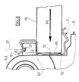
- an axial force is a force exerted parallel to the x axis ( figure 3 ) corresponding to the axis of a disk 1 (represented in phantom on figures 4 and 5 ), by tangential force, a force exerted co-axially with the disk 1 and by radial force a force exerted along a radius of the disk 1.
- a spring 3 which, viewed from the side, has substantially the shape of a numeral "5" defining a first groove 5 for fastening to a component 7 of a support 9, typically on a protruding part 7 of a yoke 9 and a second groove 11 for receiving an ear 13 of a friction element 15 typically a brake shoe.
- the shape of the first groove 5 is adapted to that of the projecting piece 7 on which it rests.
- the protruding part 7 of the yoke 9 substantially forms a square base rectangular parallelepiped whose height extends axially.
- the groove 5 has, in this advantageous case, a shape substantially U.
- one of the sides 17 of the U, preferably the side opposite the second groove 11, has an axial edge 19 applying a large force on the element salient 7.
- the infallible fastening of the spring on the support 9 is an essential feature of the present invention.
- This characteristic can be further advantageously improved by a locking of the spring 3 on the support 9, preferably on the projecting element 7.
- This locking is effected by the penetration, in a locked condition, of a male part of one of the elements to be assembled in a recess or a female cavity of the other element.
- the male element is a tongue 21 carried by the side 17 of the groove 5 of the spring 3, the female element being an axial groove 23, disposed opposite the tongue 21 (upper side on the Figures 4 to 9 ) of the protruding part 7.
- the tongue 21 is advantageously made by cutting the face 17. It may be advantageous to give the tongue 21 of the elasticity, for example by providing two grooves 25 extending the edges of this tongue.
- a tongue 21 disposed along the median plane 27 of the groove 23 does not depart from the scope of the present invention, it is advantageous to provide an angle ⁇ between the tongue 21 and the plane 27 so as to effectively oppose a traction exerted according to the arrow 29 and a tilting torque symbolized by the arrow 31.
- the angle ⁇ is preferably between 3 ° and 87 °, preferably between 10 ° and 60 ° °, more preferably is between 25 ° and 50 °.
- the angle ⁇ is equal to 45 °.
- the tongue 21 has the same slope as the end portion of the side 17 of the spring and extends beyond the edge 19 so as to enter the groove 23 of the projecting piece 7.
- the inclination of the tongue 21 allows a rapid installation of the spring 3 according to the present invention on the protruding part 7 of the support 9 with snap-in locking during the depression of the groove 5 of the spring 3 on the projecting element 7 and penetration of this tongue into the groove 23.
- the groove 23 extends over the entire axial length of the projecting parts 7, which facilitates the machining of said groove.
- the implementation of obviously or receiving cavity 23 of the tongue 21 extending over a portion of the axial length of the projecting parts 7 is not beyond the scope of the present invention. Such cavities are more expensive to make by machining but more effectively oppose axial displacement of the spring 3 on its support 7.
- the spring 3 can be equipped with other means preventing its axial displacement.
- the spring 3 comprises a first tongue 33 and a second tongue 35 orthogonal to the sides and the base of the U-shaped groove intended to bear on the axially opposite faces of the projections 7.
- the tongue 33 intended to oppose the displacement of the spring 3 during braking, (application typically by a hydraulic device, friction elements 15 on the disk 1) has a width greater than that of the tongue 35 intended to oppose the movement of the spring 3 on the protruding part 7 during release (when the friction elements 15 deviate from the disc 1).
- Grooves 37 may be provided along the base of tabs 33 and 35 so as to improve its resilience.
- a brake according to the present invention comprises four springs 3 according to the present invention, one at each of the tangential ends of each friction element.
- the brake comprises four identical, independent springs.
- the same type of spring can be adopted on brakes of different axial width.
- the implementation of springs arranged opposite each other of the disc 1 and connected by a bridge is not beyond the scope of the present invention.
- the shape of the groove 11 is adapted to that of the lugs of the friction element.
- a groove 11 of semicircular or substantially semicircular section for guiding pads with round ends.
- the illustrated advantageous example comprises a U-shaped groove for receiving the ears of a pad with "square ends".
- the radial distance between the opposite sides 39 and 41 of the U-shaped groove is substantially equal to the radial extension of the ends or ears of the pads.
- the side 39 of the groove 11 corresponds to the side of the groove 5 opposite the side 17.
- the groove 11 is provided with a first tongue 43 of axial introduction guide the end of the wafer 15 in the groove 11 and d a second tangential introduction guide tongue 45 of the end of the plate 15 in the groove 11.
- the free side 41 of the groove 11 is provided with a rib 47 ensuring its torsional stiffening.
- the guiding rigidity is not affected by wear of the plates 15 with modification of the axial position, at rest, of the shoe end 15 in the groove 11 of the spring 3.
- angles of the spring 3 are rounded so as not to be sharp and to avoid hurting a mechanic during a maintenance operation.
- the spring 3 according to the present invention is for example made of cut and folded stainless steel sheet preferably having a thickness of less than 1 mm, for example equal to 0.4 ⁇ 0.03 mm.
- stainless steel Z10CN 18.08, Z12CN 17.07 or steel SAE 30301 or 30302 is used.
- the preferred example of the brake according to the present invention illlustrée comprises a yoke 9 comprising two arms 49 and 51 disposed on either side of the disk 1 connected at each of their ends by a bridge 53 extending axially and disposed radially beyond of the disc 1.
- the bridges 53 comprise openings 55 for receiving the guide elements of a stirrup (not shown) carrying means of application, on typically hydraulic control of the friction elements 15 on the opposite major faces of the disc 1.
- a stirrup not shown
- the friction element 15 is clamped between the sides 39 and 41 of the groove 11 of the spring 3.
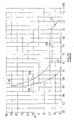
- This corresponds to the substantially horizontal zone 59 of the curve 57 for a load of the order 17 N with a displacement between 2 mm and 1.2 mm.
- Point 61 of the curve corresponds to the establishment of contact 63 ( figure 7 ) between the friction element 15 and the bottom 65 of the U-shaped groove 11. It should be noted that the point of contact 63 is located near the intersection of the bottom 65 and the side 41 of the groove 11 of the spring 3. The point 67 corresponding to the intersection of the bottom 65 and the side 39 bearing on the yoke.
- the point of contact 63 moves towards the point 67 that it reaches at the point 71 corresponding to the case illustrated on FIG. figure 8 .
- the base 65 of the groove 11 of the spring 3 has a concavity directed towards the friction element 15 with which it has seen in section, a point of contact 73.
- the base 65 rests on the yoke 9 at points 67 and 75. This configuration avoids the contact between the friction element 15 and the yoke 9, contact whose establishment generates an unpleasant noise called "klonk".
- the return during release is illustrated in 77.
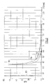
- Curve 83 on the left side of the figure 11 illustrates the rigidity of the ban of measurements, rigidity which was taken into account during the measurements expressed by the curves 57 and 79.
- the spring 3 has a very small contact surface with the yoke which is typically made of cast iron with an anti-corrosion treatment, for example based on alloys of zinc. However, this contact promotes corrosion of the spring.
- the spring 3 according to the present invention has a better corrosion resistance than the known type of spring.
- the anti-corrosion surface treatment of the spring 3 according to the present invention is not outside the scope of the present invention.
- the present invention applies in particular to the automotive industry.
- the present invention applies mainly to the construction of brakes for motor vehicles.
Landscapes
- Engineering & Computer Science (AREA)
- General Engineering & Computer Science (AREA)
- Mechanical Engineering (AREA)
- Braking Arrangements (AREA)
- Springs (AREA)
Abstract
Description
La présente invention se rapporte à un ressort de guidage et de maintien d'éléments de friction, notamment de type plaquettes et à un frein à disque comportant au moins un tel ressort.The present invention relates to a spring for guiding and holding friction elements, in particular of the type of pads and a disc brake comprising at least one such spring.
Il est connu de guider en translation axiale des plaquettes de freins à disques par des ressorts montés sur des chapes. Lors du freinage d'un véhicule porteur équipé de tels freins, les plaquettes appliquées sur chaque disque en rotation sont soumises à des forces tangentielles dirigées vers un élément du support. Les ressorts de type connu opposent une force de rappel qui ne peut être maîtrisée en fabrication en grande série au vu des tolérances minimales admissibles. Ainsi, un freinage avec décélaration importante engendre une force qui projette les plaquettes en direction de son support avec une force plus intense que la force de rappel exercée par le ressort. Le choc tangentiel de la plaquette sur le support engendre un bruit désagréable pour les occupants du véhicule appelé « klonk », qui peut de plus être interprété à tort, comme un bruit caractéristique d'une défaillance mécanique.It is known to guide in axial translation disc brake pads by springs mounted on screeds. When braking a carrier vehicle equipped with such brakes, the pads applied to each rotating disc are subjected to tangential forces directed towards a support member. The known type of springs oppose a restoring force that can not be controlled in mass production in view of the minimum allowable tolerances. Thus, braking with significant deceleration generates a force which projects the pads towards its support with a force more intense than the restoring force exerted by the spring. The tangential impact of the wafer on the support generates an unpleasant noise for the occupants of the vehicle called "klonk", which can moreover be misinterpreted as a noise characteristic of a mechanical failure.
La Demanderesse a découvert que le mauvais contrôle du guidage tangentiel des plaquettes provient d'un accrochage non performant des ressorts sur la chape. De plus, il est habituel de réunir par un pontet deux ressorts disposés en vis à vis, le premier assurant le maintien de l'extrêmité d'une première plaquette susceptible d'être appliquée sur une première face principale d'un disque, le second assurant le maintien de l'extrêmité correspondante du second patin susceptible d'être appliquée sur une seconde face principale du disque opposée à ladite première face principale. Ainsi, on est obligé de disposer d'un ressort spécifique pour chaque largeur de chape.The Applicant has discovered that the poor control of the tangential guidance of the wafers is due to non-efficient hanging of the springs on the screed. In addition, it is usual to combine by a bridge two springs arranged opposite, the first ensuring the maintenance of the end of a first plate may be applied to a first main face of a disc, the second ensuring the maintenance of the corresponding end of the second pad may be applied to a second main face of the disk opposite to said first main face. Thus, it is necessary to have a specific spring for each screed width.
C'est par conséquent, un but de la présente invention d'offrir un ressort assurant un guidage axial efficace et s'opposant aux chocs tangentiels, directs et indirects (à travers le ressort) de l'élément de friction guidé avec le support, notamment avec une chape.It is therefore an object of the present invention to provide a spring providing effective axial guidance and opposing direct and indirect tangential shocks (through the spring) of the friction element guided with the support, especially with a screed.
C'est également un but de la présente invention d'offrir un tel ressort susceptible d'exercer une force de rappel importante.It is also an object of the present invention to provide such a spring capable of exerting a large restoring force.
C'est également un but de la présente invention d'offrir un ressort présentant un encombrement limité.It is also an object of the present invention to provide a spring with limited bulk.
C'est aussi un but de la présente invention d'offrir un ressort ayant une grande longévité y compris dans des conditions d'utilisation sévères.It is also an object of the present invention to provide a spring having a long life including under severe conditions of use.
C'est aussi un but de la présente invention d'offir un tel ressort résistant à la corrosion.It is also an object of the present invention to provide such a spring resistant to corrosion.
C'est aussi un but de la présente invention d'offrir un tel ressort susceptible d'être monté sur une grande variété de freins à disque notamment sur des freins à disque ayant des chapes de diverses largeurs.It is also an object of the present invention to provide such a spring capable of being mounted on a wide variety of disc brakes including disc brakes having screeds of various widths.
C'est également un but de la présente invention d'offrir un frein à disques comportant au moins un, de préférence quatre tels ressorts.It is also an object of the present invention to provide a disk brake having at least one, preferably four such springs.
C'est également un but de la présente invention d'offrir un frein à disques présentant un fonctionnement particulièrement sûr.It is also an object of the present invention to provide a disk brake having a particularly safe operation.
C'est aussi un but de la présente invention d'offrir un frein disque ayant un prix de revient modéré.It is also an object of the present invention to provide a disk brake having a moderate cost price.
C'est aussi un but de la présente invention d'offir un frein à disques particulièrement silencieux.It is also an object of the present invention to provide a particularly quiet disc brake.
Ces buts sont atteints par un ressort selon la présente invention comportant des moyens d'assemblage capables de coopérer avec des moyens d'assemblage complémentaires portés par un support, typiquement par la chape d'un frein à disque. L'engagement des moyens d'assemblage du ressort avec ceux du support assure leur verrouillage mutuel avec un maintien du ressort sur le support. Avantageusement, on fixe le ressort sur le support d'un seul côté, le côté opposé du ressort étant libre avec, de préférence un débattement important dans la condition libre, avant le montage de l'élément de friction.These objects are achieved by a spring according to the present invention comprising assembly means capable of cooperating with complementary assembly means carried by a support, typically by the clevis of a disk brake. The engagement of the assembly means of the spring with those of the support ensures their mutual locking with a maintenance of the spring on the support. Advantageously, the spring is fixed on the support on one side, the opposite side of the spring being free with, preferably a large clearance in the free condition, before the mounting of the friction element.
L'invention a principalement pour objet un ressort de guidage axial et de maintien radial des éléments de friction d'un frein à disque comportant des moyens d'assemblage capables de coopérer avec des moyens d'assemblage complémentaires portés par un support caractérisé en ce que la coopération desdits moyens d'assemblage assure leur verrouillage mutuel.The invention mainly relates to an axial guide spring and radial support of the friction elements of a disk brake comprising assembly means capable of cooperating with complementary assembly means borne by a support, characterized in that the cooperation of said assembly means ensures their mutual locking.
L'invention a également pour objet un tel ressort caractérisé en ce que les moyens d'assemblage portés par le ressort comportent un élément mâle capable de coopérer avec un moyen femelle en pénétrant dans ledit moyen femelle lors d'une opération de verrouillage par encliquetage.The invention also relates to such a spring characterized in that the assembly means carried by the spring comprise a male element capable of cooperating with a female means by penetrating into said female means during a latching locking operation.
L'invention a également pour objet un tel ressort caractérisé en ce que ledit ressort est un ressort à lame en tôle découpée et pliée et en ce que l'élément mâle ait une languette.The invention also relates to such a spring characterized in that said spring is a leaf spring sheet cut and folded and in that the male element has a tongue.
L'invention a également pour objet un tel ressort caractérisé en ce que ledit ressort a, en vue de côté, sensiblement la forme du chiffre « 5 ».The invention also relates to such a spring characterized in that said spring has, in side view, substantially the shape of the digit "5".
L'invention a également pour objet un frein à disque caractérisé par le fait qu'il comporte au moins un ressort selon l'invention.The invention also relates to a disk brake characterized in that it comprises at least one spring according to the invention.
L'invention a également pour objet un tel frein à disque caractérisé en ce qu'il comporte deux plaquettes formant éléments de friction, chaque plaquette comportant deux oreilles radialement opposées, chaque oreille étant guidée par un ressort selon l'invention.The subject of the invention is also such a disk brake, characterized in that it comprises two platelets forming friction elements, each plate having two radially opposite lugs, each lug being guided by a spring according to the invention.
L'invention a également pour objet un tel frein à disque caractérisé en ce que le support des ressorts est formé par une chape comportant un premier bras disposé en vis à vis d'une première face principale d'un disque et un second bras disposé en vis à vis d'une seconde face du disque opposé à la dite première face du disque, les deux bras étant reliés par au moins un pontet.The invention also relates to such a disc brake characterized in that the support of the springs is formed by a yoke having a first arm disposed opposite a first main face of a disc and a second arm arranged in against a second face of the disk opposite to said first face of the disk, the two arms being connected by at least one bridge.
L'invention a également pour objet un tel frein à disque caractérisé en ce que le ressort est solidarisé avec le support par une unique extrêmité l'extrêmité opposée étant libre.The invention also relates to such a disk brake characterized in that the spring is secured to the support by a single end the opposite end being free.
L'invention a également pour objet un tel frein a disque caractérisé en ce qu'au repos l'extrêmité libre du ressort est écartée par rapport au support.The invention also relates to such a disc brake characterized in that at rest the free end of the spring is spaced relative to the support.
L'invention a également pour objet un tel frein à disque caractérisé en ce que les éléments de friction sont des plaquettes à oreilles carrées et en ce que chaque ressort comporte une gorge adaptée au guidage axial d'une oreille carrée de patin de frein.The invention also relates to such a disk brake characterized in that the friction elements are square ear pads and in that each spring has a groove adapted for axial guidance of a square ear brake pad.
L'invention sera mieux comprise au moyen de la description ci-après et des figures annexées données comme des exemples non limitatifs et sur lesquelles :
- la
figure 1 est une vue en perspective de l'exemple préféré de réalisation d'un ressort selon la présente invention ; - la
figure 2 est une vue en perspective du ressort de lafigure 1 après rotation d'un angle de 90° ; - la
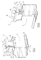
figure 3 est une vue en plan d'une chape de frein à disques selon la présente invention dont la partie inférieure sur la figure est équipée d'une plaquette de freins alors que la plaquette de la partie supérieure de la figure ainsi que le ressort supérieur droit ne sont pas représentés; - la
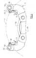
figure 4 est une vue de côté de la chape de lafigure 3 avant le montage de patins de frein ; - la
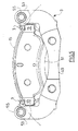
figure 5 est une vue analogue après le montage des patins ; - la
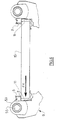
figure 6 est une vue schématique partielle de côté de la chape de lafigure 3 équipée d'un patin exerçant une force correspondant à celle obtenue au cours du montage d'un patin réel ; - la
figure 7 est une vue schématique partielle, illustrant les forces exercées par un patin monté, dans une condition de repos, c'est à dire sans entraînement du patin par le disque ; - la
figure 8 est une vue analogue lors d'un freinage ; - la
figure 9 est une vue analogue lors d'un freinage d'intensité très importante ; - la
figure 10 est une courbe illustrant la position et par suite la déformation de l'exemple préféré de réalisation du ressort selon la présente invention en fonction de la force de rappel exercée ; - la
figure 11 comporte deux courbes analogues avec une échelle des forces plus étendue.
- the
figure 1 is a perspective view of the preferred embodiment of a spring according to the present invention; - the
figure 2 is a perspective view of the spring of thefigure 1 after rotation at an angle of 90 °; - the
figure 3 is a plan view of a disk brake yoke according to the present invention, the lower part of which in the figure is equipped with a brake pad while the plate of the upper part of the figure as well as the upper right spring are not represented; - the
figure 4 is a side view of the coping of thefigure 3 before mounting brake pads; - the
figure 5 is a similar view after the mounting of the pads; - the
figure 6 is a partial schematic side view of the coping of thefigure 3 equipped with a shoe exerting a force corresponding to that obtained during the assembly of a real shoe; - the
figure 7 is a partial schematic view, illustrating the forces exerted by a mounted pad, in a rest condition, that is to say without drive pad by the disc; - the
figure 8 is a similar view during braking; - the
figure 9 is a similar view during braking of very important intensity; - the
figure 10 is a curve illustrating the position and consequently the deformation of the preferred embodiment of the spring according to the present invention as a function of the restoring force exerted; - the
figure 11 has two similar curves with a larger scale of forces.
Sur les
Sur les
La forme de la première gorge 5 est adaptée à celle de la pièce saillante 7 sur laquelle elle repose. Dans l'exemple avantageux illustré la pièce saillante 7 de la chape 9 forme sensiblement un parallélépipède rectangle de base carrée dont la hauteur s'étend axialement. La gorge 5 a, dans ce cas avantageux, une forme sensiblement en U. Avantageusement, un des côtés 17 du U, de préférence, le côté opposé à la seconde gorge 11, présente une arête axiale 19 appliquant une force importante sur l'élément saillant 7.The shape of the
La fixation infaillible du ressort sur le support 9 est une caractéristique essentielle de la présente invention. Cette caractéristique peut être encore avantageusement améliorée par un verrouillage du ressort 3 sur le support 9, de préférence sur l'élément saillant 7. Ce verrouillage s'effectue par la pénétration, en condition verrouillée, d'une pièce mâle de l'un des éléments à assembler dans un évidemment ou une cavité femelle de l'autre élément. Dans l'exemple avantageux, non limitatif, illustré, l'élément mâle est une languette 21 portée par le côté 17 de la gorge 5 du ressort 3, l'élément femelle étant une gorge 23 axiale, disposée en vis à vis de la languette 21 (face supérieure sur les
La languette 21 est avantageusement réalisée par découpe de la face 17. Il peut s'avérer avantageux de conférer à la languette 21 de l'élasticité, par exemple en ménageant deux gorges 25 prolongeant les bords de cette languette.The
Bien que la mise en oeuvre d'une languette 21 disposée selon le plan médian 27 de la gorge 23 ne sort pas du cadre de la présente invention, il est avantageux de ménager un angle α entre la languette 21 et le plan 27 de manière à s'opposer efficacement à une traction exercée selon la flèche 29 et à un couple de basculement symbolisé par la flèche 31. L'angle α est, de préférence compris entre 3° et 87°, de manière préférée est compris entre 10° et 60°, de manière encore préférée est compris entre 25° et 50°. Dans l'exemple avantageux illustré, l'angle α est égal à 45°. Dans l'exemple préféré illustré, la languette 21 présente la même pente que la partie d'extrêmité du côté 17 du ressort et se prolonge au delà de l'arête 19 de manière à pouvoir pénétrer dans la gorge 23 de la pièce saillante 7.Although the implementation of a
De plus, l'inclinaison de la languette 21 permet une pose rapide du ressort 3 selon la présente invention sur la pièce saillante 7 du support 9 avec verrouillage par encliquetage lors de l'enfoncement de la gorge 5 du ressort 3 sur l'élément saillant 7 et pénétration de cette languette dans la gorge 23.In addition, the inclination of the
Dans l'exemple illustré, la gorge 23 s'étend sur toute la longueur axiale des pièces saillantes 7, ce qui facilite la réalisation par usinage de ladite gorge. Toutefois, la mise en oeuvre d'évidemment ou de cavité de réception 23 de la languette 21 s'étendant sur une partie de la longueur axiale des pièces saillantes 7 ne sort pas du cadre de la présente invention. De telles cavités sont plus coûteuses à réaliser par usinage mais s'opposent plus efficacement à un déplacement axial du ressort 3 sur son support 7.In the example shown, the
Le ressort 3 peut être équipé d'autres moyens empêchant son déplacement axial. Dans l'exemple illustré, le ressort 3 comporte une première languette 33 et une deuxième languette 35 orthogonales aux côtés et à la base de la gorge en U destinées à prendre appui sur les faces axialement opposées des pièces saillantes 7. Avantageusement, la languette 33 destinée à s'opposer au déplacement du ressort 3 lors du freinage, (application typiquement par un dispositif hydraulique, des éléments de friction 15 sur le disque 1) a une largeur supérieure à celle de la languette 35 destinée à s'opposer au déplacement du ressort 3 sur la pièce saillante 7 lors du défreinage (lorsque les éléments de friction 15 s'écartent du disque 1). Des gorges 37 peuvent être ménagées le long de la base des languettes 33 et 35 de manière à en améliorer l'élasticité. Il est bien entendu que la mise en oeuvre d'autres moyens de fixation du ressort 3 sur le support 9, telle que la mise en oeuvre d'un rivet ou d'un boulon passant par une ouverture pratiquée dans le ressort ne sort pas du cadre de la présente invention. Comme il sera expliqué ci-après en référence aux
Avantageusement, un frein selon la présente invention comporte quatre ressorts 3 selon la présente invention, un à chacune des extrêmités tangentielles de chaque élément de friction. Avantageusement, le frein comporte quatre ressorts identiques, indépendants. Ainsi, un même type de ressort peut être adopté sur des freins de largeur axiale différente. Toutefois, la mise en oeuvre de ressorts disposés en vis à vis de part et d'autre du disque 1 et reliés par un pontet ne sort pas du cadre de la présente invention.Advantageously, a brake according to the present invention comprises four
La forme de la gorge 11 est adaptée à celle des oreilles de l'élément de friction. Ainsi, on utilisera une gorge 11 à section semi-circulaire ou sensiblement semi- circulaire pour le guidage de patins à bouts ronds. L'exemple avantageux illustré comporte une gorge en U de réception des oreilles d'un patin « à bouts carrés ». La distance radiale entre les côtés opposés 39 et 41 de la gorge en U est sensiblement égale à l'extension radiale des bouts ou oreilles des patins. Le côté 39 de la gorge 11 correspond au côté de la gorge 5 opposé au côté 17. Avantageusement, la gorge 11 est munie d'une première languette 43 de guidage d'introduction axiale du bout de la plaquette 15 dans la gorge 11 et d'une deuxième languette 45 de guidage d'introduction tangentielle du bout de la plaquette 15 dans la gorge 11. Avantageusement, le côté libre 41 de la gorge 11 est muni d'une nervure 47 assurant sa rigidification en torsion. Ainsi, la rigidité de guidage n'est pas affectée par une usure des plaquettes 15 avec modification de la position axiale, au repos, du bout de patin 15 dans la gorge 11 du ressort 3.The shape of the
Avantageusement, les angles du ressort 3 sont arrondis pour ne pas être coupants et pour éviter de blesser une mécanicien lors d'une opération de maintenance.Advantageously, the angles of the
Le ressort 3 selon la présente invention est par exemple réalisé en tôle d'acier inoxydable découpée et pliée ayant de préférence une épaisseur inférieure à 1 mm, par exemple égale à 0,4 ± 0,03 mm. On utilise par exemple de l'acier inoxydable Z10CN 18.08, Z12CN 17.07 ou de l'acier SAE 30301, ou 30302.The
L'exemple préféré de frein selon la présente invention illlustrée comporte une chape 9 comprenant deux bras 49 et 51 disposés de part et d'autre du disque 1 reliés à chacune de leurs extrêmités par un pontet 53 s'étendant axialement et disposé radialement au delà du disque 1. Les pontets 53 comportent des ouvertures 55 de réception des éléments de guidage d'un étrier (non représenté) portant des moyens d'application, sur commande typiquement hydraulique des éléments de friction 15 sur les faces principales opposées du disque 1. Toutefois, il est bien entendu que la mise en oeuvre d'autres supports 9 ou d'autres moyens d'application des éléments de friction 15 ne sort pas du cadre de la présente invention.The preferred example of the brake according to the present invention illlustrée comprises a
Sur la
Sur les shémas explicatifs 6 à 9, les éléments de friction 15 ne sont représentés que partiellement.In explanatory diagrams 6 to 9, the
Sur la
La courbe 83 sur la partie gauche de la
Au vu des forces mises en j eu, la situation de la
La présente invention s'applique notamment à l'industrie automobile.The present invention applies in particular to the automotive industry.
La présente invention s'applique principalement à la construction de freins pour véhicules automobiles.The present invention applies mainly to the construction of brakes for motor vehicles.
Claims (14)
Applications Claiming Priority (3)
| Application Number | Priority Date | Filing Date | Title |
|---|---|---|---|
| FR9914024A FR2800140B1 (en) | 1999-10-26 | 1999-10-26 | FRICTION ELEMENTS GUIDING SPRING AND DISC BRAKE COMPRISING AT LEAST ONE SUCH SPRING |
| EP00971475A EP1224409B1 (en) | 1999-10-26 | 2000-10-20 | Guide spring for friction elements and disc brake comprising same |
| PCT/FR2000/002938 WO2001031223A1 (en) | 1999-10-26 | 2000-10-20 | Guide spring for friction elements and disc brake comprising same |
Related Parent Applications (1)
| Application Number | Title | Priority Date | Filing Date |
|---|---|---|---|
| EP00971475A Division EP1224409B1 (en) | 1999-10-26 | 2000-10-20 | Guide spring for friction elements and disc brake comprising same |
Publications (3)
| Publication Number | Publication Date |
|---|---|
| EP2141380A1 true EP2141380A1 (en) | 2010-01-06 |
| EP2141380B1 EP2141380B1 (en) | 2017-01-04 |
| EP2141380B2 EP2141380B2 (en) | 2024-05-29 |
Family
ID=9551873
Family Applications (2)
| Application Number | Title | Priority Date | Filing Date |
|---|---|---|---|
| EP00971475A Revoked EP1224409B1 (en) | 1999-10-26 | 2000-10-20 | Guide spring for friction elements and disc brake comprising same |
| EP09168999.2A Expired - Lifetime EP2141380B2 (en) | 1999-10-26 | 2000-10-20 | Guide spring for friction elements and disc brake comprising at least one such spring. |
Family Applications Before (1)
| Application Number | Title | Priority Date | Filing Date |
|---|---|---|---|
| EP00971475A Revoked EP1224409B1 (en) | 1999-10-26 | 2000-10-20 | Guide spring for friction elements and disc brake comprising same |
Country Status (20)
| Country | Link |
|---|---|
| US (1) | US6527090B1 (en) |
| EP (2) | EP1224409B1 (en) |
| JP (1) | JP3806815B2 (en) |
| KR (1) | KR100687013B1 (en) |
| CN (1) | CN100378364C (en) |
| AT (1) | ATE495382T1 (en) |
| AU (1) | AU770779B2 (en) |
| BR (1) | BR0015278B1 (en) |
| CY (1) | CY1111387T1 (en) |
| CZ (1) | CZ305214B6 (en) |
| DE (1) | DE60045517D1 (en) |
| DK (1) | DK1224409T3 (en) |
| ES (2) | ES2621200T3 (en) |
| FR (1) | FR2800140B1 (en) |
| MX (1) | MXPA02004281A (en) |
| PL (1) | PL197755B1 (en) |
| PT (1) | PT1224409E (en) |
| RU (1) | RU2264566C2 (en) |
| TR (3) | TR200201118T2 (en) |
| WO (1) | WO2001031223A1 (en) |
Cited By (2)
| Publication number | Priority date | Publication date | Assignee | Title |
|---|---|---|---|---|
| WO2015155708A1 (en) | 2014-04-08 | 2015-10-15 | Freni Brembo S.P.A. | Disc brake pad, spring for disc brake caliper and disk brake caliper assembly |
| DE102022200646A1 (en) | 2022-01-20 | 2023-07-20 | Hl Mando Corporation | Brake arrangement for a vehicle disc brake with a noise-dampening pad spring or pad clip |
Families Citing this family (77)
| Publication number | Priority date | Publication date | Assignee | Title |
|---|---|---|---|---|
| WO2003027527A1 (en) * | 2001-09-25 | 2003-04-03 | Kelsey-Hayes Company | Pad retraction spring for a brake shoe assembly and a disc brake assembly |
| DE10233446A1 (en) * | 2002-07-24 | 2004-02-12 | Continental Teves Ag & Co. Ohg | Brake holder of floating calliper disc brake for motor vehicles has brake pad guide spring fitted radially on brake holder and locked thereupon by means of at least one retaining clip both radially and axially |
| KR100694014B1 (en) * | 2002-11-05 | 2007-03-12 | 주식회사 만도 | The Pad return springs of Disk Brake for Vehicles |
| FR2849132B1 (en) * | 2002-12-20 | 2006-03-03 | Bosch Gmbh Robert | MEANS FOR GUIDING BRAKE PADS WITH INCREASED LIFESPAN AND DISK BRAKE COMPRISING SUCH MEANS AND METHOD FOR PRODUCING SUCH MEANS |
| FR2851310B1 (en) | 2003-02-17 | 2006-04-28 | Bosch Gmbh Robert | FRICTION MEMBER AND DISC BRAKE FOR A MOTOR VEHICLE PROVIDED WITH SAID FRICTION MEMBER |
| JP4546398B2 (en) * | 2003-07-31 | 2010-09-15 | フレニ・ブレンボ エス・ピー・エー | Spring member for disc brake caliper and caliper for disc brake |
| AU2003300759A1 (en) * | 2003-12-30 | 2005-07-21 | Freni Brembo S.P.A. | Pad and capillar body for a disc brake |
| FR2870907B1 (en) * | 2004-05-27 | 2008-07-11 | Bosch Gmbh Robert | SPRING FOR HOLDING AND GUIDING A FRICTION MEANS AND DISC BRAKE HAVING AT LEAST ONE SUCH SPRING |
| DE102004062731A1 (en) * | 2004-06-04 | 2005-12-29 | Continental Teves Ag & Co. Ohg | Disc brake with Federanordung |
| US7163089B2 (en) * | 2004-06-14 | 2007-01-16 | Akebono Brake Industry Co., Ltd. | Pad clip of disc brake apparatus |
| DE102004053026B4 (en) * | 2004-11-03 | 2007-07-05 | Knorr-Bremse Systeme für Nutzfahrzeuge GmbH | Pad carrier plate of a disc brake |
| JP4589190B2 (en) * | 2005-07-28 | 2010-12-01 | 日立オートモティブシステムズ株式会社 | Disc brake |
| US20070029148A1 (en) * | 2005-08-08 | 2007-02-08 | Akebono Corporation North America | Caliper brake pad clip |
| JP2007263307A (en) * | 2006-03-29 | 2007-10-11 | Akebono Brake Ind Co Ltd | Pad clip for disc brake |
| JP4650400B2 (en) * | 2006-11-20 | 2011-03-16 | トヨタ自動車株式会社 | Disc brake device |
| FR2910095B1 (en) | 2006-12-15 | 2009-01-30 | Bosch Gmbh Robert | DISC BRAKE HAVING ELASTIC RECALL MEANS FOR THE BRAKE PAD IN ITS REST POSITION. |
| AU2014203265B2 (en) * | 2007-05-28 | 2016-10-20 | Applied Explosives Technology Pty Limited | Improved low energy breaking agent |
| US8276717B1 (en) * | 2007-11-15 | 2012-10-02 | Robert Bosch Gmbh | High/low shoe abutment |
| FR2925634B1 (en) * | 2007-12-21 | 2010-04-02 | Bosch Gmbh Robert | SYSTEM FOR MOUNTING DISC BRAKE PAD. |
| JP4818250B2 (en) * | 2007-12-27 | 2011-11-16 | 日立オートモティブシステムズ株式会社 | Disc brake |
| FR2927388B1 (en) | 2008-02-11 | 2010-05-28 | Bosch Gmbh Robert | GUIDING A DISC BRAKE PAD HOLDER |
| DE102008013514A1 (en) | 2008-03-11 | 2009-09-17 | TRW KFZ-Ausrüstung GmbH | Disc brake with orientation-secured installation of the brake pads |
| JP4766280B2 (en) * | 2008-06-13 | 2011-09-07 | 曙ブレーキ工業株式会社 | Pad clip for disc brake device |
| JP5126786B2 (en) * | 2008-07-11 | 2013-01-23 | 曙ブレーキ工業株式会社 | Pad clip for disc brake device |
| US20100051393A1 (en) * | 2008-08-29 | 2010-03-04 | Nissan Technical Center North America, Inc. | Brake pad clip with integrated pad return spring and wear indicator |
| JP4780569B2 (en) * | 2008-09-04 | 2011-09-28 | 曙ブレーキ工業株式会社 | Pad clip for disc brake device |
| JP4716232B2 (en) * | 2008-10-31 | 2011-07-06 | 曙ブレーキ工業株式会社 | Pad clip for disc brake device |
| JP5213818B2 (en) * | 2009-09-01 | 2013-06-19 | 日信工業株式会社 | Vehicle disc brake |
| JP5583533B2 (en) * | 2009-09-28 | 2014-09-03 | 日立オートモティブシステムズ株式会社 | Disc brake |
| KR101317152B1 (en) * | 2009-11-30 | 2013-10-11 | 주식회사 만도 | Disk brake |
| JP5469501B2 (en) * | 2010-03-29 | 2014-04-16 | 曙ブレーキ工業株式会社 | Pad clip for disc brake device |
| US8397880B2 (en) * | 2010-05-27 | 2013-03-19 | Akebono Brake Corporation | Pad retraction device |
| US8393441B2 (en) | 2011-01-24 | 2013-03-12 | Akebono Brake Corporation | Spreader spring |
| US8376092B2 (en) | 2011-02-10 | 2013-02-19 | Akebono Brake Corp. | Pad retraction device |
| JP2012180905A (en) * | 2011-03-02 | 2012-09-20 | Nissin Kogyo Co Ltd | Vehicle disc brake |
| DE102011100160A1 (en) | 2011-05-02 | 2012-11-08 | Lucas Automotive Gmbh | Disk brake for motor vehicle brake system, comprises guide unit for guiding return spring in disk brake, where restoring force is exerted on brake pad assembly by return spring and brake pad assembly comprises brake lining carrier |
| JP5837343B2 (en) * | 2011-06-30 | 2015-12-24 | 日立オートモティブシステムズ株式会社 | Disc brake |
| FR2984437B1 (en) | 2011-12-15 | 2014-01-17 | Bosch Gmbh Robert | LATCH GUIDING MEMBER OF A DISC BRAKE PATIN AND DISK BRAKE EQUIPPED WITH SUCH GUIDING BODIES |
| FR2984438B1 (en) | 2011-12-15 | 2014-01-17 | Bosch Gmbh Robert | RADIAL SPRING OF DISC DISC BRAKE PAD AND BRAKE PADS AND BRAKES EQUIPPED WITH SUCH RADIAL SPRINGS |
| FR2984439B1 (en) | 2011-12-15 | 2014-06-27 | Bosch Gmbh Robert | SPRING BRAKE GUIDE SPRING GUIDE AND DISK BRAKE EQUIPPED WITH SUCH GUIDING BODIES |
| FR2984440B1 (en) | 2011-12-15 | 2014-02-28 | Bosch Gmbh Robert | DISC BRAKE SLIDER SLIDE AND DISK BRAKE EQUIPPED WITH SUCH SLIDER |
| US9568055B2 (en) * | 2012-01-26 | 2017-02-14 | Kelsey-Hayes Company | Clip for use in a disc brake assembly and disc brake assembly including such a clip |
| DE102012002734A1 (en) * | 2012-02-10 | 2013-08-14 | Knorr-Bremse Systeme für Nutzfahrzeuge GmbH | Belaghaltesystem a disc brake of a motor vehicle |
| DE102012010932A1 (en) * | 2012-06-01 | 2013-12-05 | Lucas Automotive Gmbh | Guide means for a brake lining arrangement |
| JP5323227B2 (en) * | 2012-06-07 | 2013-10-23 | 曙ブレーキ工業株式会社 | Pad clip for disc brake device |
| US8973720B2 (en) * | 2012-08-17 | 2015-03-10 | Bendix Spicer Foundation Brake Llc | Disc brake pad mounting and retention system and method |
| US8544614B1 (en) * | 2012-08-17 | 2013-10-01 | Bendix Spicer Foundation Brake Llc | Disc brake pad mounting and retention system and method |
| US8973240B2 (en) | 2012-08-17 | 2015-03-10 | Bendix Spicer Foundation Brake Llc | Disc brake pad mounting and retention system and method |
| JP5858244B2 (en) * | 2013-04-25 | 2016-02-10 | 株式会社アドヴィックス | Disc brake device |
| FR3005127B1 (en) * | 2013-04-29 | 2015-04-17 | Chassis Brakes Int Bv | "BRAKE DISC BRAKE WITH STABILIZED BRAKES, AND ASSOCIATED METHODS OF ASSEMBLING AND REPLACING A SKATE" |
| FR3005334B1 (en) * | 2013-05-02 | 2015-04-24 | Chassis Brakes Int Bv | "DISC BRAKE COMPRISING A PRELOAD SPRING OF A BRAKE PAD" |
| JP5855606B2 (en) * | 2013-06-18 | 2016-02-09 | 日信工業株式会社 | Vehicle disc brake |
| JP6134926B2 (en) * | 2013-06-28 | 2017-05-31 | 日立オートモティブシステムズ株式会社 | Disc brake |
| US9341220B2 (en) * | 2013-07-12 | 2016-05-17 | Bendix Spicer Foundation Brake Llc | Brake pad retention device and method |
| JP6338346B2 (en) * | 2013-10-15 | 2018-06-06 | 曙ブレーキ工業株式会社 | Disc brake pad and disc brake device |
| US9049905B2 (en) * | 2013-10-23 | 2015-06-09 | GM Global Technology Operations LLC | Clip and coupling assembly |
| US9206867B2 (en) | 2014-02-25 | 2015-12-08 | Akebono Brake Industry Co., Ltd. | Pad clip with nonlinear stiffness |
| DE102014113617A1 (en) * | 2014-09-22 | 2016-03-24 | Knorr-Bremse Systeme für Nutzfahrzeuge GmbH | Brake pad holder of a disc brake, disc brake and brake pad |
| KR101628600B1 (en) * | 2015-01-06 | 2016-06-08 | 현대자동차주식회사 | Pad liner for reducing drag in brake caliper |
| CN107429767B (en) * | 2015-03-05 | 2020-03-20 | 凯尔西-海耶斯公司 | Brake clip for a disc brake assembly and disc brake assembly comprising such a brake clip |
| DE102015111847A1 (en) * | 2015-07-22 | 2017-01-26 | Knorr-Bremse Systeme für Nutzfahrzeuge GmbH | Pad retainer mounting tool with disc brake locking device, disc brake and brake pad set |
| KR101629189B1 (en) * | 2015-08-07 | 2016-06-10 | 대경정밀공업 주식회사 | Automobile brake pads support clip |
| US9506514B1 (en) * | 2015-09-09 | 2016-11-29 | Bendix Spicer Foundation Brake Llc | Wedge spring clip |
| CN105587803A (en) * | 2016-03-21 | 2016-05-18 | 广州汽车集团股份有限公司 | Brake caliper leaf spring and brake caliper assembly |
| CN106763328A (en) * | 2016-12-02 | 2017-05-31 | 浙江万向系统有限公司 | A kind of new support, spring piece fixed structure |
| US10415660B2 (en) | 2016-12-08 | 2019-09-17 | Kelsey-Hayes Company | Brake clip for disc brake assembly and disc brake assembly including such a brake clip |
| US11287000B2 (en) * | 2017-09-07 | 2022-03-29 | Hitachi Astemo, Ltd. | Vehicular disc brake |
| DE102017129672A1 (en) * | 2017-12-12 | 2019-06-13 | Knorr-Bremse Systeme für Nutzfahrzeuge GmbH | Disc brake for a commercial vehicle and brake pad set |
| DE102018005036A1 (en) * | 2018-06-25 | 2020-01-02 | Lucas Automotive Gmbh | Guide element for a vehicle disc brake |
| JP2020003006A (en) * | 2018-06-28 | 2020-01-09 | 日信工業株式会社 | Disc brake for vehicle |
| JP2020003007A (en) * | 2018-06-28 | 2020-01-09 | 日信工業株式会社 | Disc brake for vehicle |
| JP7012161B2 (en) * | 2018-07-25 | 2022-01-27 | 日立Astemo株式会社 | Disc brake |
| US10774889B2 (en) | 2018-08-01 | 2020-09-15 | Mando Corporation | Brake assembly with brake pad carrier and clip |
| DE102019212896A1 (en) * | 2019-04-17 | 2020-10-22 | Continental Teves Ag & Co. Ohg | Motor vehicle disc brake lining with friction lining return spring assembly |
| FR3097923B1 (en) * | 2019-06-26 | 2022-07-29 | Foundation Brakes France | "Disc brake comprising at least one elastic return spring of a brake pad, elastic return spring, replacement kit and mounting method" |
| EP4365458A1 (en) * | 2022-11-04 | 2024-05-08 | Zf Aftermarket Iberica, S.L. | Spring for a brake lining assembly of a braking device |
| CN118482122B (en) * | 2024-07-16 | 2024-09-20 | 万向(上海)技术有限公司 | Braking device |
Citations (5)
| Publication number | Priority date | Publication date | Assignee | Title |
|---|---|---|---|---|
| JPS5857528A (en) * | 1981-09-29 | 1983-04-05 | Nissan Motor Co Ltd | Disc brake |
| EP0732521A1 (en) * | 1995-03-16 | 1996-09-18 | Akebono Brake Industry Co., Ltd. | Pad clip for disc brake |
| DE19610611A1 (en) * | 1996-03-18 | 1997-09-25 | Lucas Ind Plc | Part brake disc brake |
| US5901815A (en) * | 1995-02-20 | 1999-05-11 | Tokico Ltd. | Disk brake |
| US5941348A (en) | 1996-10-23 | 1999-08-24 | Akebono Brake Industry Co., Ltd. | Pad clip for disc brake |
Family Cites Families (19)
| Publication number | Priority date | Publication date | Assignee | Title |
|---|---|---|---|---|
| JPS5550373U (en) * | 1978-09-29 | 1980-04-02 | ||
| JPS57159038U (en) † | 1981-03-31 | 1982-10-06 | ||
| DE3938881A1 (en) † | 1989-11-24 | 1991-05-29 | Teves Gmbh Alfred | Brake shoe spring for disc brake - has support and housing, with central spring and central section and two sprung arms |
| JPH0874898A (en) * | 1994-06-29 | 1996-03-19 | Aisin Seiki Co Ltd | Pad clip for disc brake |
| JP3346053B2 (en) * | 1994-11-07 | 2002-11-18 | 住友電気工業株式会社 | Disc brake |
| JP3213191B2 (en) * | 1995-01-27 | 2001-10-02 | トキコ株式会社 | Disc brake |
| DE19626303A1 (en) * | 1996-07-01 | 1998-01-08 | Teves Gmbh Alfred | Retaining spring for a housing of a partial brake disc brake |
| JP3816588B2 (en) † | 1996-07-09 | 2006-08-30 | 株式会社日立製作所 | Disc brake |
| JP3273436B2 (en) † | 1996-07-09 | 2002-04-08 | トキコ株式会社 | Disc brake |
| JP3838586B2 (en) * | 1996-09-25 | 2006-10-25 | 曙ブレーキ工業株式会社 | Disc brake pad clip |
| JPH10110756A (en) * | 1996-10-03 | 1998-04-28 | Tokico Ltd | Disc brake |
| GB9701025D0 (en) * | 1997-01-18 | 1997-03-05 | Lucas Ind Plc | Improvements relating to brake assemblies |
| KR100267190B1 (en) * | 1997-06-05 | 2000-10-16 | 서평원 | Apparatus of front-end for down frequency converter of mobile communication base station |
| KR19990000824A (en) * | 1997-06-10 | 1999-01-15 | 구자홍 | Mounting structure of bakery structure |
| JPH1163035A (en) * | 1997-08-28 | 1999-03-05 | Aisin Seiki Co Ltd | Disc brake |
| JP3303780B2 (en) * | 1998-07-08 | 2002-07-22 | 住友電気工業株式会社 | Disc brake |
| JP4039753B2 (en) * | 1998-11-04 | 2008-01-30 | 曙ブレーキ工業株式会社 | Disc brake |
| US6223866B1 (en) * | 2000-06-30 | 2001-05-01 | Kelsey-Hayes Company | Damped pad spring for use in a disc brake assembly |
| US6378666B1 (en) * | 2001-11-16 | 2002-04-30 | Robert Bosch Corporation | Disc brake |
-
1999
- 1999-10-26 FR FR9914024A patent/FR2800140B1/en not_active Expired - Lifetime
-
2000
- 2000-10-20 KR KR1020027005352A patent/KR100687013B1/en active IP Right Grant
- 2000-10-20 BR BRPI0015278-1A patent/BR0015278B1/en not_active IP Right Cessation
- 2000-10-20 WO PCT/FR2000/002938 patent/WO2001031223A1/en active Application Filing
- 2000-10-20 US US09/701,325 patent/US6527090B1/en not_active Expired - Lifetime
- 2000-10-20 CN CNB008148775A patent/CN100378364C/en not_active Expired - Lifetime
- 2000-10-20 JP JP2001533335A patent/JP3806815B2/en not_active Expired - Lifetime
- 2000-10-20 AU AU10325/01A patent/AU770779B2/en not_active Expired
- 2000-10-20 RU RU2002112752/11A patent/RU2264566C2/en active
- 2000-10-20 DK DK00971475.9T patent/DK1224409T3/en active
- 2000-10-20 CZ CZ2002-1483A patent/CZ305214B6/en not_active IP Right Cessation
- 2000-10-20 PT PT00971475T patent/PT1224409E/en unknown
- 2000-10-20 DE DE60045517T patent/DE60045517D1/en not_active Expired - Lifetime
- 2000-10-20 TR TR2002/01118T patent/TR200201118T2/en unknown
- 2000-10-20 ES ES09168999.2T patent/ES2621200T3/en not_active Expired - Lifetime
- 2000-10-20 TR TR2004/02898T patent/TR200402898T2/en unknown
- 2000-10-20 TR TR2005/03610T patent/TR200503610T1/en unknown
- 2000-10-20 AT AT00971475T patent/ATE495382T1/en active
- 2000-10-20 PL PL354530A patent/PL197755B1/en unknown
- 2000-10-20 ES ES00971475T patent/ES2359682T3/en not_active Expired - Lifetime
- 2000-10-20 EP EP00971475A patent/EP1224409B1/en not_active Revoked
- 2000-10-20 EP EP09168999.2A patent/EP2141380B2/en not_active Expired - Lifetime
- 2000-10-20 MX MXPA02004281A patent/MXPA02004281A/en unknown
-
2011
- 2011-04-12 CY CY20111100373T patent/CY1111387T1/en unknown
Patent Citations (5)
| Publication number | Priority date | Publication date | Assignee | Title |
|---|---|---|---|---|
| JPS5857528A (en) * | 1981-09-29 | 1983-04-05 | Nissan Motor Co Ltd | Disc brake |
| US5901815A (en) * | 1995-02-20 | 1999-05-11 | Tokico Ltd. | Disk brake |
| EP0732521A1 (en) * | 1995-03-16 | 1996-09-18 | Akebono Brake Industry Co., Ltd. | Pad clip for disc brake |
| DE19610611A1 (en) * | 1996-03-18 | 1997-09-25 | Lucas Ind Plc | Part brake disc brake |
| US5941348A (en) | 1996-10-23 | 1999-08-24 | Akebono Brake Industry Co., Ltd. | Pad clip for disc brake |
Cited By (3)
| Publication number | Priority date | Publication date | Assignee | Title |
|---|---|---|---|---|
| WO2015155708A1 (en) | 2014-04-08 | 2015-10-15 | Freni Brembo S.P.A. | Disc brake pad, spring for disc brake caliper and disk brake caliper assembly |
| US10316912B2 (en) | 2014-04-08 | 2019-06-11 | Freni Brembo S.P.A. | Disc brake pad, spring for disc brake caliper and disk brake caliper assembly |
| DE102022200646A1 (en) | 2022-01-20 | 2023-07-20 | Hl Mando Corporation | Brake arrangement for a vehicle disc brake with a noise-dampening pad spring or pad clip |
Also Published As
Similar Documents
| Publication | Publication Date | Title |
|---|---|---|
| EP2141380B1 (en) | Guide spring for friction elements and disc brake comprising at least one such spring. | |
| KR101990170B1 (en) | Pad retention system of a disc brake of a motor vehicle | |
| EP2792899B1 (en) | Disc brake equipped with elastic returning means and with plastic deformation wear compensation means for brake pads | |
| US6296085B1 (en) | Disk brake | |
| JP6185654B2 (en) | Disc brake with brake, pad and preload spring | |
| FR3005127A1 (en) | "BRAKE DISC BRAKE WITH STABILIZED BRAKES, AND ASSOCIATED METHODS OF ASSEMBLING AND REPLACING A SKATE" | |
| EP0203841B1 (en) | Disc brake spring | |
| US7458447B2 (en) | Disc brake assembly | |
| EP0080949B1 (en) | Disk brake, and brake shoe for such a brake | |
| US4537291A (en) | Brake shoe assembly including brake shoe spring | |
| EP0059128B1 (en) | Pad spring for disc brakes | |
| FR2645230A1 (en) | BLADE SPRING FOR HOLDING THE LINING SUPPORT OF A DISC BRAKE IN A LOW POSITION | |
| WO2013087854A1 (en) | Lock-equipped member for guiding a disc brake pad and disc brake provided with such guiding members | |
| FR2791406A1 (en) | DEVICE FOR MOUNTING A DIAPHRAGM ON A CLUTCH COVER | |
| FR2704035A1 (en) | Assembly of a friction element equipped with a disc brake spring. | |
| FR2582763A1 (en) | THRUST PLATE SPRING FOR DISC BRAKE | |
| EP0830519B1 (en) | Disc brake using a rotationally biased pad | |
| EP0092470B1 (en) | Damping device for a drum brake, brake support plate incorporating the same and a drum brake with support plate provided with such a device | |
| FR2925634A1 (en) | Brake friction pad mounting device for vehicle, has sliding plate with end opposite to another end of plate exerting pressure force on lateral side of housing when mounting device is mounted on yoke joint | |
| EP0162744B1 (en) | Pad spring for a floating caliper disc brake, and disc brake equipped with such a spring | |
| EP0030184B1 (en) | Disc brake | |
| EP1548295B1 (en) | Assembly for fastening an exhaust system suspension element to a support of the underbody of a motor vehicle | |
| EP2791536B1 (en) | Disc brake pad | |
| FR2965027A1 (en) | Disk brake for motor vehicle, has outboard disk brake pad integrated with outer arm of brake caliper by fixation screws, to allow guided displacement of brake caliper with respect to fixed support by outboard disk brake pad | |
| EP0044772B1 (en) | Disc brake with moving caliper |
Legal Events
| Date | Code | Title | Description |
|---|---|---|---|
| PUAI | Public reference made under article 153(3) epc to a published international application that has entered the european phase |
Free format text: ORIGINAL CODE: 0009012 |
|
| AC | Divisional application: reference to earlier application |
Ref document number: 1224409 Country of ref document: EP Kind code of ref document: P |
|
| AK | Designated contracting states |
Kind code of ref document: A1 Designated state(s): AT BE CH CY DE DK ES FI FR GB GR IE IT LI LU MC NL PT SE |
|
| RIN1 | Information on inventor provided before grant (corrected) |
Inventor name: BONNET, STEPHANE Inventor name: BARILLOT, ALAIN Inventor name: KUBIC, OLIVIER Inventor name: CHAUVEAU, CHRISTOPHE |
|
| 17P | Request for examination filed |
Effective date: 20100706 |
|
| 17Q | First examination report despatched |
Effective date: 20100816 |
|
| GRAP | Despatch of communication of intention to grant a patent |
Free format text: ORIGINAL CODE: EPIDOSNIGR1 |
|
| INTG | Intention to grant announced |
Effective date: 20161004 |
|
| STAA | Information on the status of an ep patent application or granted ep patent |
Free format text: STATUS: GRANT OF PATENT IS INTENDED |
|
| GRAS | Grant fee paid |
Free format text: ORIGINAL CODE: EPIDOSNIGR3 |
|
| GRAA | (expected) grant |
Free format text: ORIGINAL CODE: 0009210 |
|
| STAA | Information on the status of an ep patent application or granted ep patent |
Free format text: STATUS: THE PATENT HAS BEEN GRANTED |
|
| AC | Divisional application: reference to earlier application |
Ref document number: 1224409 Country of ref document: EP Kind code of ref document: P |
|
| AK | Designated contracting states |
Kind code of ref document: B1 Designated state(s): AT BE CH CY DE DK ES FI FR GB GR IE IT LI LU MC NL PT SE |
|
| REG | Reference to a national code |
Ref country code: GB Ref legal event code: FG4D Free format text: NOT ENGLISH |
|
| REG | Reference to a national code |
Ref country code: CH Ref legal event code: EP |
|
| REG | Reference to a national code |
Ref country code: AT Ref legal event code: REF Ref document number: 859557 Country of ref document: AT Kind code of ref document: T Effective date: 20170115 |
|
| REG | Reference to a national code |
Ref country code: IE Ref legal event code: FG4D Free format text: LANGUAGE OF EP DOCUMENT: FRENCH |
|
| REG | Reference to a national code |
Ref country code: DE Ref legal event code: R096 Ref document number: 60049526 Country of ref document: DE |
|
| REG | Reference to a national code |
Ref country code: SE Ref legal event code: TRGR |
|
| REG | Reference to a national code |
Ref country code: NL Ref legal event code: MP Effective date: 20170104 |
|
| REG | Reference to a national code |
Ref country code: AT Ref legal event code: MK05 Ref document number: 859557 Country of ref document: AT Kind code of ref document: T Effective date: 20170104 |
|
| PG25 | Lapsed in a contracting state [announced via postgrant information from national office to epo] |
Ref country code: NL Free format text: LAPSE BECAUSE OF FAILURE TO SUBMIT A TRANSLATION OF THE DESCRIPTION OR TO PAY THE FEE WITHIN THE PRESCRIBED TIME-LIMIT Effective date: 20170104 |
|
| REG | Reference to a national code |
Ref country code: ES Ref legal event code: FG2A Ref document number: 2621200 Country of ref document: ES Kind code of ref document: T3 Effective date: 20170703 |
|
| PG25 | Lapsed in a contracting state [announced via postgrant information from national office to epo] |
Ref country code: GR Free format text: LAPSE BECAUSE OF FAILURE TO SUBMIT A TRANSLATION OF THE DESCRIPTION OR TO PAY THE FEE WITHIN THE PRESCRIBED TIME-LIMIT Effective date: 20170405 Ref country code: FI Free format text: LAPSE BECAUSE OF FAILURE TO SUBMIT A TRANSLATION OF THE DESCRIPTION OR TO PAY THE FEE WITHIN THE PRESCRIBED TIME-LIMIT Effective date: 20170104 |
|
| PG25 | Lapsed in a contracting state [announced via postgrant information from national office to epo] |
Ref country code: AT Free format text: LAPSE BECAUSE OF FAILURE TO SUBMIT A TRANSLATION OF THE DESCRIPTION OR TO PAY THE FEE WITHIN THE PRESCRIBED TIME-LIMIT Effective date: 20170104 Ref country code: PT Free format text: LAPSE BECAUSE OF FAILURE TO SUBMIT A TRANSLATION OF THE DESCRIPTION OR TO PAY THE FEE WITHIN THE PRESCRIBED TIME-LIMIT Effective date: 20170504 |
|
| REG | Reference to a national code |
Ref country code: DE Ref legal event code: R026 Ref document number: 60049526 Country of ref document: DE |
|
| PLBI | Opposition filed |
Free format text: ORIGINAL CODE: 0009260 |
|
| PLBI | Opposition filed |
Free format text: ORIGINAL CODE: 0009260 |
|
| 26 | Opposition filed |
Opponent name: VRI-VERBAND DER REIBBELAGINDUSTRIE E.V. Effective date: 20170901 |
|
| REG | Reference to a national code |
Ref country code: FR Ref legal event code: PLFP Year of fee payment: 18 |
|
| PLAX | Notice of opposition and request to file observation + time limit sent |
Free format text: ORIGINAL CODE: EPIDOSNOBS2 |
|
| 26 | Opposition filed |
Opponent name: ITT MANUFACTURING ENTERPRISES LLC Effective date: 20171004 |
|
| PG25 | Lapsed in a contracting state [announced via postgrant information from national office to epo] |
Ref country code: DK Free format text: LAPSE BECAUSE OF FAILURE TO SUBMIT A TRANSLATION OF THE DESCRIPTION OR TO PAY THE FEE WITHIN THE PRESCRIBED TIME-LIMIT Effective date: 20170104 |
|
| PGFP | Annual fee paid to national office [announced via postgrant information from national office to epo] |
Ref country code: NL Payment date: 20171023 Year of fee payment: 18 |
|
| PLBB | Reply of patent proprietor to notice(s) of opposition received |
Free format text: ORIGINAL CODE: EPIDOSNOBS3 |
|
| PG25 | Lapsed in a contracting state [announced via postgrant information from national office to epo] |
Ref country code: MC Free format text: LAPSE BECAUSE OF FAILURE TO SUBMIT A TRANSLATION OF THE DESCRIPTION OR TO PAY THE FEE WITHIN THE PRESCRIBED TIME-LIMIT Effective date: 20170104 |
|
| REG | Reference to a national code |
Ref country code: FR Ref legal event code: PLFP Year of fee payment: 19 |
|
| PG25 | Lapsed in a contracting state [announced via postgrant information from national office to epo] |
Ref country code: CY Free format text: LAPSE BECAUSE OF NON-PAYMENT OF DUE FEES Effective date: 20170104 |
|
| PGFP | Annual fee paid to national office [announced via postgrant information from national office to epo] |
Ref country code: LU Payment date: 20191022 Year of fee payment: 20 |
|
| RDAF | Communication despatched that patent is revoked |
Free format text: ORIGINAL CODE: EPIDOSNREV1 |
|
| PGFP | Annual fee paid to national office [announced via postgrant information from national office to epo] |
Ref country code: DE Payment date: 20191212 Year of fee payment: 20 Ref country code: IE Payment date: 20191021 Year of fee payment: 20 Ref country code: SE Payment date: 20191023 Year of fee payment: 20 |
|
| PGFP | Annual fee paid to national office [announced via postgrant information from national office to epo] |
Ref country code: FR Payment date: 20191022 Year of fee payment: 20 Ref country code: BE Payment date: 20191022 Year of fee payment: 20 Ref country code: IT Payment date: 20191021 Year of fee payment: 20 Ref country code: ES Payment date: 20191120 Year of fee payment: 20 |
|
| PGFP | Annual fee paid to national office [announced via postgrant information from national office to epo] |
Ref country code: CH Payment date: 20191023 Year of fee payment: 20 |
|
| APAH | Appeal reference modified |
Free format text: ORIGINAL CODE: EPIDOSCREFNO |
|
| APBM | Appeal reference recorded |
Free format text: ORIGINAL CODE: EPIDOSNREFNO |
|
| APBP | Date of receipt of notice of appeal recorded |
Free format text: ORIGINAL CODE: EPIDOSNNOA2O |
|
| RAP2 | Party data changed (patent owner data changed or rights of a patent transferred) |
Owner name: ROBERT BOSCH GMBH |
|
| PGFP | Annual fee paid to national office [announced via postgrant information from national office to epo] |
Ref country code: GB Payment date: 20191023 Year of fee payment: 20 |
|
| APBQ | Date of receipt of statement of grounds of appeal recorded |
Free format text: ORIGINAL CODE: EPIDOSNNOA3O |
|
| REG | Reference to a national code |
Ref country code: DE Ref legal event code: R071 Ref document number: 60049526 Country of ref document: DE |
|
| REG | Reference to a national code |
Ref country code: CH Ref legal event code: PL |
|
| REG | Reference to a national code |
Ref country code: GB Ref legal event code: PE20 Expiry date: 20201019 |
|
| REG | Reference to a national code |
Ref country code: IE Ref legal event code: MK9A |
|
| REG | Reference to a national code |
Ref country code: BE Ref legal event code: MK Effective date: 20201020 |
|
| REG | Reference to a national code |
Ref country code: ES Ref legal event code: FD2A Effective date: 20210127 |
|
| PG25 | Lapsed in a contracting state [announced via postgrant information from national office to epo] |
Ref country code: GB Free format text: LAPSE BECAUSE OF EXPIRATION OF PROTECTION Effective date: 20201019 Ref country code: IE Free format text: LAPSE BECAUSE OF EXPIRATION OF PROTECTION Effective date: 20201020 |
|
| PG25 | Lapsed in a contracting state [announced via postgrant information from national office to epo] |
Ref country code: ES Free format text: LAPSE BECAUSE OF EXPIRATION OF PROTECTION Effective date: 20201021 |
|
| APBU | Appeal procedure closed |
Free format text: ORIGINAL CODE: EPIDOSNNOA9O |
|
| PLAY | Examination report in opposition despatched + time limit |
Free format text: ORIGINAL CODE: EPIDOSNORE2 |
|
| PLBC | Reply to examination report in opposition received |
Free format text: ORIGINAL CODE: EPIDOSNORE3 |
|
| PLAP | Information related to despatch of examination report in opposition + time limit deleted |
Free format text: ORIGINAL CODE: EPIDOSDORE2 |
|
| PLAT | Information related to reply to examination report in opposition deleted |
Free format text: ORIGINAL CODE: EPIDOSDORE3 |
|
| PLAY | Examination report in opposition despatched + time limit |
Free format text: ORIGINAL CODE: EPIDOSNORE2 |
|
| PLAH | Information related to despatch of examination report in opposition + time limit modified |
Free format text: ORIGINAL CODE: EPIDOSCORE2 |
|
| PLBC | Reply to examination report in opposition received |
Free format text: ORIGINAL CODE: EPIDOSNORE3 |
|
| PUAH | Patent maintained in amended form |
Free format text: ORIGINAL CODE: 0009272 |
|
| STAA | Information on the status of an ep patent application or granted ep patent |
Free format text: STATUS: PATENT MAINTAINED AS AMENDED |
|
| 27A | Patent maintained in amended form |
Effective date: 20240529 |
|
| AK | Designated contracting states |
Kind code of ref document: B2 Designated state(s): AT BE CH CY DE DK ES FI FR GB GR IE IT LI LU MC NL PT SE |
|
| REG | Reference to a national code |
Ref country code: DE Ref legal event code: R102 Ref document number: 60049526 Country of ref document: DE |