EP2141315A2 - Tür, Fenster oder dergl. - Google Patents
Tür, Fenster oder dergl. Download PDFInfo
- Publication number
- EP2141315A2 EP2141315A2 EP09164113A EP09164113A EP2141315A2 EP 2141315 A2 EP2141315 A2 EP 2141315A2 EP 09164113 A EP09164113 A EP 09164113A EP 09164113 A EP09164113 A EP 09164113A EP 2141315 A2 EP2141315 A2 EP 2141315A2
- Authority
- EP
- European Patent Office
- Prior art keywords
- door
- window
- plastic component
- conductor
- conductor track
- Prior art date
- Legal status (The legal status is an assumption and is not a legal conclusion. Google has not performed a legal analysis and makes no representation as to the accuracy of the status listed.)
- Withdrawn
Links
- 239000011888 foil Substances 0.000 claims abstract description 12
- 239000002184 metal Substances 0.000 claims abstract description 12
- 229910052751 metal Inorganic materials 0.000 claims abstract description 12
- 239000004020 conductor Substances 0.000 claims description 54
- 238000001465 metallisation Methods 0.000 claims description 8
- 238000003825 pressing Methods 0.000 claims description 3
- 238000012806 monitoring device Methods 0.000 claims description 2
- 238000003780 insertion Methods 0.000 claims 1
- 230000037431 insertion Effects 0.000 claims 1
- 230000005855 radiation Effects 0.000 abstract 1
- 238000004519 manufacturing process Methods 0.000 description 5
- 238000000034 method Methods 0.000 description 3
- 229910000679 solder Inorganic materials 0.000 description 3
- 238000005553 drilling Methods 0.000 description 2
- RYGMFSIKBFXOCR-UHFFFAOYSA-N Copper Chemical compound [Cu] RYGMFSIKBFXOCR-UHFFFAOYSA-N 0.000 description 1
- 230000000712 assembly Effects 0.000 description 1
- 238000000429 assembly Methods 0.000 description 1
- 244000052616 bacterial pathogen Species 0.000 description 1
- 229910052802 copper Inorganic materials 0.000 description 1
- 239000010949 copper Substances 0.000 description 1
- 238000013461 design Methods 0.000 description 1
- 238000011161 development Methods 0.000 description 1
- 230000000694 effects Effects 0.000 description 1
- 230000005611 electricity Effects 0.000 description 1
- 238000003801 milling Methods 0.000 description 1
- 238000012545 processing Methods 0.000 description 1
- 239000004065 semiconductor Substances 0.000 description 1
Images



Classifications
-
- E—FIXED CONSTRUCTIONS
- E05—LOCKS; KEYS; WINDOW OR DOOR FITTINGS; SAFES
- E05F—DEVICES FOR MOVING WINGS INTO OPEN OR CLOSED POSITION; CHECKS FOR WINGS; WING FITTINGS NOT OTHERWISE PROVIDED FOR, CONCERNED WITH THE FUNCTIONING OF THE WING
- E05F3/00—Closers or openers with braking devices, e.g. checks; Construction of pneumatic or liquid braking devices
- E05F3/22—Additional arrangements for closers, e.g. for holding the wing in opened or other position
- E05F3/227—Additional arrangements for closers, e.g. for holding the wing in opened or other position mounted at the top of wings, e.g. details related to closer housings, covers, end caps or rails therefor
-
- E—FIXED CONSTRUCTIONS
- E05—LOCKS; KEYS; WINDOW OR DOOR FITTINGS; SAFES
- E05F—DEVICES FOR MOVING WINGS INTO OPEN OR CLOSED POSITION; CHECKS FOR WINGS; WING FITTINGS NOT OTHERWISE PROVIDED FOR, CONCERNED WITH THE FUNCTIONING OF THE WING
- E05F15/00—Power-operated mechanisms for wings
- E05F15/60—Power-operated mechanisms for wings using electrical actuators
- E05F15/603—Power-operated mechanisms for wings using electrical actuators using rotary electromotors
- E05F15/611—Power-operated mechanisms for wings using electrical actuators using rotary electromotors for swinging wings
- E05F15/63—Power-operated mechanisms for wings using electrical actuators using rotary electromotors for swinging wings operated by swinging arms
-
- E—FIXED CONSTRUCTIONS
- E05—LOCKS; KEYS; WINDOW OR DOOR FITTINGS; SAFES
- E05Y—INDEXING SCHEME ASSOCIATED WITH SUBCLASSES E05D AND E05F, RELATING TO CONSTRUCTION ELEMENTS, ELECTRIC CONTROL, POWER SUPPLY, POWER SIGNAL OR TRANSMISSION, USER INTERFACES, MOUNTING OR COUPLING, DETAILS, ACCESSORIES, AUXILIARY OPERATIONS NOT OTHERWISE PROVIDED FOR, APPLICATION THEREOF
- E05Y2400/00—Electronic control; Electrical power; Power supply; Power or signal transmission; User interfaces
- E05Y2400/65—Power or signal transmission
- E05Y2400/654—Power or signal transmission by electrical cables
-
- E—FIXED CONSTRUCTIONS
- E05—LOCKS; KEYS; WINDOW OR DOOR FITTINGS; SAFES
- E05Y—INDEXING SCHEME ASSOCIATED WITH SUBCLASSES E05D AND E05F, RELATING TO CONSTRUCTION ELEMENTS, ELECTRIC CONTROL, POWER SUPPLY, POWER SIGNAL OR TRANSMISSION, USER INTERFACES, MOUNTING OR COUPLING, DETAILS, ACCESSORIES, AUXILIARY OPERATIONS NOT OTHERWISE PROVIDED FOR, APPLICATION THEREOF
- E05Y2900/00—Application of doors, windows, wings or fittings thereof
- E05Y2900/10—Application of doors, windows, wings or fittings thereof for buildings or parts thereof
- E05Y2900/13—Type of wing
- E05Y2900/132—Doors
Definitions
- the invention relates to a door, a window or the like. According to the preamble of claim 1.
- the DE 10 2005 061 724 A1 describes a drive for actuating a movable door leaf, wherein when establishing a mechanical connection between a drive component and a base profile at the same time an electrical connection is made.
- this document does not disclose any evidence for the production of electrical conductors.
- the invention has for its object to improve a generic door to the effect that the application of the at least one conductor to the at least one plastic component can be significantly simplified.
- the course of the at least one conductor track can be cut into the at least one plastic component and subsequently metallized or at least a conductor track can be pressed onto the plastic component.
- the conductor can be relatively simple and thus produce inexpensive.
- the plastic component does not necessarily have to be made from two plastic components. A likewise relatively expensive galvanization is not absolutely necessary.
- the plastic component may be arranged in or on a door or window drive or on other assemblies on doors or windows and be designed for example as a cover, hydraulic housing, base plate or as a cover. It can also be arranged in the door leaf itself, a plastic component, for example, for transmitting signals to the wing arranged components, such as the drive or a lock.
- the plastic of the at least one plastic component may have metallization nuclei.
- the laser beam fulfills two functions in a plastic provided with metallization nuclei. First, the laser beam mills the course of the track in the plastic. Secondly, the laser beam activates the metallization nuclei in the plastic, so that a subsequent metallization of the milling can be successfully carried out.
- the milled cut is electroless, for example with copper, metallizable. This can be done for example in a suitable metallizing.
- the at least one conductor track can be arranged on at least one metal foil, wherein the metal foil can be pressed onto the at least one plastic component. Furthermore, the printed conductor can be punched out of the metal foil during the pressing process and fused to the plastic component. As a result, the conductor can be applied to the plastic component in a few process steps.
- the electrical device may be a drive device, which usually requires a large number of electrical connections, so that the advantage according to the invention is particularly evident.
- the advantage according to the invention also comes into play when the electrical device is a monitoring device.
- the at least one plastic component may have at least one plate-like region, which is provided on its opposite sides with conductor tracks.
- both sides of the plate-like area can accommodate traces without the need for additional circuit boards.
- the opposite sides of the plate-like area are provided by means of an internally metallizable bore, then arranged on the opposite sides conductor tracks can be plated through the metallizable bore.
- electronic components such as semiconductors, are soldered into the at least one conductor track.
- the plastic component thus fulfills the function of a circuit carrier.
- At least one plug connection for plugging in a connector can be arranged on the at least one plastic component and the at least one printed conductor.
- Fig. 1 shows a lid 10 for receiving a circuit board 11 of a rotary encoder not shown here.
- the encoder With the encoder, a likewise not shown drive motor for rotating a revolving door can be controlled.
- the circuit board 11 is a separate component, on which the required circuit for the rotary encoder is housed.
- the circuit board 11 is locked in the lid 10. The production of the circuit board 11 and its assembly are manufacturing steps, the reduction beats noticeable especially in large quantities.
- Fig. 2 shows a cover 20, in which a circuit 21 for the encoder also not shown here is arranged directly on the lid 20.
- the circuit board 11 off Fig. 1 and the associated assembly can therefore be omitted here. Instead, printed conductors 22, 23, 24 and 25 are arranged directly on the lid 20.
- cut-outs preferably with the aid of a laser beam, are produced in the cover 20 in accordance with the course of the conductor tracks 22, 23, 24 and 25.
- the milled cuts are metallized in a next processing step.
- the conductor tracks 22, 23, 24 and 25 can be arranged on a metal foil not shown here.
- the metal foil can be pressed onto the cover 20.
- the conductor tracks 22, 23, 24 and 25 can be punched out of the metal foil and fused to the cover 20.
- Connection contacts 26 of electronic components which are arranged on the side not visible here, facing away from the viewer, can be inserted through holes provided for this purpose which strike the printed conductors 22, 23, 24 and 25 directly. In this way, the electronic components with minimal effort can be electrically connected to the tracks 22, 23, 24 and 25. By a solder joint, the electronic components can be permanently connected to the tracks 22, 23, 24 and 25.
- Fig. 3 shows a drive device 30 of a door not shown here.
- a hydraulic housing 31 of the drive device 30 conductor tracks 32 are applied directly.
- the conductor tracks 32 can also be produced by means of a laser beam and a subsequent metallization, or by the already described pressing-on process of a metal foil comprising the conductor tracks 32.
- the hydraulic housing 31 is made of a metallization germs having plastic.
- the metallization can preferably be carried out without electricity.
- Fig. 4 shows the door operator 30 after the hydraulic housing 31 has been removed.
- a base plate 40 there is likewise provided a conductor track 41 which electrically connects a controller 42 to a motor 43.
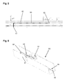
- a conductor 50 is provided below the base plate 40, which is through-plated by internally metallized holes 51 and 52 with the conductor 41 (see Fig. 5 ).
- Fig. 6 shows a cover 60, on the plug-in terminals 61, 62 and 63 are arranged.
- To the plug-in terminals 61, 62 and 63 lead a plurality of tracks 64 and 65, which were prepared in the manner already described.
- the plug-in terminals 61, 62 and 63 are mounted directly on the tracks 64 and 65, wherein the plug-in terminals 61, 62 and 63 are preferably electrically connected to the tracks 64 and 65 by means of internally metallized holes. In this way, the manufacturing and assembly costs can be minimized.
- the plug-in terminals 61, 62 and 63 can be permanently connected to the tracks 64 and 65.
- a lid 70 is shown, as for example in the door drive 30 in Fig. 3 Can be used.
- the cover 70 is provided with a relatively complex circuit.
- conductor tracks 71, 72, 73, 74, 75, 76, 77 and 78 are applied in the manner already described here several times.
- electronic components 79, 700, 701 702 and 703 which are each connected by internally metallized holes with the tracks 71, 72, 73, 74, 75, 76, 77 and 78 by solder joints.
Landscapes
- Power-Operated Mechanisms For Wings (AREA)
- Shielding Devices Or Components To Electric Or Magnetic Fields (AREA)
Abstract
Description
- Die Erfindung betrifft eine Tür, ein Fenster oder dergl. nach dem Oberbegriff des Anspruchs 1.
- Aus der
DE 100 05 026 A1 ist ein Multifunktionsmodul eines Bewegungsmelders bekannt, das aus zwei Kunststoffkomponenten herstellbar ist, von denen eine Kunststoffkomponente galvanisierbar und die andere Kunststoffkomponente nicht galvanisierbar ist. Auf die galvanisierbare Kunststoffkomponente können Leiterbahnen galvanisch aufgebracht werden. Nachteilig hierbei ist jedoch, dass zwei Kunststoffkomponenten erforderlich sind. - Die
DE 10 2005 061 724 A1 beschreibt einen Antrieb zum Betätigen eines beweglichen Türflügels, wobei beim Herstellen einer mechanischen Verbindung zwischen einer Antriebskomponente und einem Grundprofil gleichzeitig auch eine elektrische Verbindung hergestellt wird. Diese Druckschrift offenbart jedoch keine Hinweise zur Herstellung von elektrischen Leiterbahnen. - Der Erfindung liegt die Aufgabe zugrunde, eine gattungsgemäße Tür dahingehend zu verbessern, dass das Aufbringen der mindestens einen Leiterbahn auf das mindestens eine Kunststoffbauteil deutlich vereinfacht werden kann.
- Die Aufgabe wird durch die Merkmale des Anspruchs 1 gelöst.
- Die Unteransprüche bilden vorteilhafte Ausgestaltungsmöglichkeiten der Erfindung.
- Erfindungsgemäß ist bei einer Tür, einem Fenster oder dergl. der eingangs genannten Art der Verlauf der mindestens einen Leiterbahn in das mindestens eine Kunststoffbauteil einfräsbar und anschließend metallisierbar oder die mindestens eine Leiterbahn ist auf das Kunststoffbauteil aufpressbar. Auf diese Weise lässt sich die Leiterbahn relativ einfach und somit kostengünstig herstellen. Das Kunststoffbauteil muss nicht zwingend aus zwei Kunststoffkomponenten hergestellt werden. Eine ebenfalls relativ aufwändige Galvanisierung ist auch nicht zwingend erforderlich. Das Kunststoffbauteil kann in oder an einem Tür- oder Fensterantrieb oder an anderen Baugruppen an Türen oder Fenstern angeordnet sein und beispielsweise als Deckel, Hydraulikgehäuse, Grundplatte oder als Abdeckung ausgebildet sein. Es kann auch ein Kunststoffbauteil im Türblatt selbst angeordnet sein, beispielsweise zum Übertragen von Signalen zu am Flügel angeordneten Bauteilen, wie dem Antrieb oder einem Schloss.
- Damit die Aufbringung des elektrisch leitenden Werkstoffes besonders einfach und schnell erfolgen kann, kann der Kunststoff des mindestens einen Kunststoffbauteils Metallisierungskeime aufweisen.
- Bezüglich der Gestaltung des Verlaufs der mindestens einen Leiterbahn hat man sehr viele Freiheiten, wenn die Einfräsung mit einem Laserstrahl herstellbar ist. Der Laserstrahl erfüllt bei einem mit Metallisierungskeimen versehenen Kunststoff zwei Funktionen. Erstens fräst der Laserstrahl den Verlauf der Leiterbahn in den Kunststoff ein. Zweitens aktiviert der Laserstrahl die Metallisierungskeime im Kunststoff, so dass eine anschließende Metallisierung der Einfräsung erfolgreich durchgeführt werden kann.
- Besonders vorteilhaft ist es, wenn die Einfräsung stromlos, beispielsweise mit Kupfer, metallisierbar ist. Dies kann beispielsweise in einem dazu geeigneten Metallisierungsbad geschehen.
- Die mindestens eine Leiterbahn kann auf mindestens einer Metallfolie angeordnet werden, wobei die Metallfolie auf das mindestens eine Kunststoffbauteil aufgepresst werden kann. Ferner kann die Leiterbahn beim Aufpressvorgang aus der Metallfolie ausgestanzt und mit dem Kunststoffbauteil verschmolzen werden. Dadurch lässt sich die Leiterbahn in wenigen Prozessschritten auf das Kunststoffbauteil aufbringen.
- In einer bevorzugten Ausführungsform kann die elektrische Einrichtung eine Antriebseinrichtung sein, die in der Regel eine Vielzahl elektrischer Verbindungen erfordert, so dass der erfindungsgemäße Vorteil besonders deutlich zum Tragen kommt.
- Aus demselben Grund kommt der erfindungsgemäße Vorteil ebenfalls zum Tragen, wenn die elektrische Einrichtung eine Überwachungseinrichtung ist.
- Das mindestens eine Kunststoffbauteil kann mindestens einen plattenähnlichen Bereich aufweisen, der auf seinen gegenüberliegenden Seiten mit Leiterbahnen versehen ist. Somit können beide Seiten des plattenähnlichen Bereichs Leiterbahnen aufnehmen, ohne dass es zusätzlicher Leiterplatten bedarf.
- Wenn die gegenüberliegenden Seiten des plattenähnlichen Bereichs mittels einer innen metallisierbaren Bohrung versehen sind, dann können die auf den gegenüberliegenden Seiten angeordneten Leiterbahnen mittels der metallisierbaren Bohrung durchkontaktiert werden.
- Zweckmäßigerweise können elektronische Bauteile, wie beispielsweise Halbleiter, in die mindestens eine Leiterbahn eingelötet werden.
- Ebenso ist es möglich auf dem mindestens einen Kunststoffbauteil mindestens eine integrierte Schaltung anzuordnen. Das Kunststoffbauteil erfüllt somit auch die Funktion eines Schaltungsträgers.
- In einer Weiterbildung der Erfindung kann auf dem mindestens einen Kunststoffbauteil und der mindestens einen Leiterbahn mindestens ein Steckanschluss zum Einstecken eine Steckverbinders angeordnet werden.
- Im Nachfolgenden werden Ausführungsbeispiele in der Zeichnung anhand der Figuren näher erläutert.
- Dabei zeigen:
- Fig. 1
- eine perspektivische Ansicht auf einen Deckel eines Drehgebers einer Tür aus dem Stand der Technik;
- Fig. 2
- eine perspektivische Ansicht auf den Deckel des Drehgebers der erfindungsgemäßen Tür;
- Fig. 3
- eine perspektivische Ansicht auf einen Türantrieb;
- Fig. 4
- eine weitere perspektivische Ansicht auf den Türantrieb aus
Fig. 3 ; - Fig. 5
- eine weitere perspektivische Ansicht auf den Türantrieb aus
Fig. 3 ; - Fig. 6
- eine perspektivische Ansicht auf eine Abdeckung;
- Fig. 7
- eine perspektivische Ansicht auf einen Deckel.
-
Fig. 1 zeigt einen Deckel 10 zur Aufnahme einer Schaltungsplatine 11 eines hier nicht näher dargestellten Drehgebers. Mit dem Drehgeber kann ein ebenfalls nicht näher dargestellter Antriebsmotor zum Drehen einer Drehtür gesteuert werden. Die Schaltungsplatine 11 ist ein separates Bauteil, auf dem die erforderliche Schaltung für den Drehgeber untergebracht ist. Die Schaltungsplatine 11 ist in den Deckel 10 eingerastet. Die Herstellung der Schaltungsplatine 11 und ihre Montage sind Fertigungsschritte, deren Einsparung besonders bei großen Stückzahlen merklich zu Buche schlägt. -
Fig. 2 zeigt einen Deckel 20, bei dem eine Schaltung 21 für den hier ebenfalls nicht näher dargestellten Drehgeber unmittelbar auf dem Deckel 20 angeordnet ist. Die Schaltungsplatine 11 ausFig. 1 und die mit ihr verbundene Montage kann hier also entfallen. Stattdessen sind Leiterbahnen 22, 23, 24 und 25 direkt auf dem Deckel 20 angeordnet. - Zur Herstellung der Leiterbahnen 22, 23, 24 und 25 werden in den Deckel 20 entsprechend dem Verlauf der Leiterbahnen 22, 23, 24 und 25 Einfräsungen, vorzugsweise mithilfe eines Laserstrahls erzeugt. Die Einfräsungen werden in einem nächsten Bearbeitungsschritt metallisiert.
- Alternativ dazu ist es jedoch auch möglich, die Leiterbahnen 22, 23, 24 und 25 auf einer hier nicht näher dargestellten Metallfolie anzuordnen. Die Metallfolie kann auf den Deckel 20 aufgepresst werden. Beim Aufpressvorgang der Metallfolie können die Leiterbahnen 22, 23, 24 und 25 aus der Metallfolie ausgestanzt und mit dem Deckel 20 verschmolzen werden.
- Anschlusskontakte 26 von elektronischen Bauteilen, die auf der hier nicht erkennbaren, dem Betrachter abgewandten Seite angeordnet sind, können durch dafür vorgesehene Bohrungen, die direkt auf die Leiterbahnen 22, 23, 24 und 25 treffen, gesteckt werden. Auf diese Weise können die elektronischen Bauteile mit geringstem Aufwand elektrisch mit den Leiterbahnen 22, 23, 24 und 25 verbunden werden. Durch eine Lötverbindung können die elektronischen Bauteile dauerhaft mit den Leiterbahnen 22, 23, 24 und 25 verbunden werden.
-
Fig. 3 zeigt eine Antriebseinrichtung 30 einer hier nicht näher dargestellten Tür. Auf einem Hydraulikgehäuse 31 der Antriebseinrichtung 30 sind Leiterbahnen 32 unmittelbar aufgebracht. Auch die Leiterbahnen 32 können mittels eines Laserstrahles und einer nachfolgenden Metallisierung hergestellt werden oder durch den bereits beschriebenen Aufpressvorgang einer die Leiterbahnen 32 umfassenden Metallfolie. Für die Herstellung der Leiterbahnen 32 mittels des Laserstrahles ist es sinnvoll, wenn das Hydraulikgehäuse 31 aus einem Metallisierungskeime aufweisenden Kunststoff hergestellt ist. Die Metallisierung kann vorzugsweise stromlos erfolgen. -
Fig. 4 zeigt den Türantrieb 30, nachdem das Hydraulikgehäuse 31 entfernt wurde. Somit erkennt man, dass unterhalb des Hydraulikgehäuses 31 auf einer Grundplatte 40 ebenfalls eine Leiterbahn 41 vorgesehen ist, die eine Steuerung 42 elektrisch mit einem Motor 43 verbindet. - Unterhalb der Grundplatte 40 ist eine Leiterbahn 50 vorgesehen, die durch innen metallisierte Bohrungen 51 und 52 mit der Leiterbahn 41 durchkontaktiert ist (siehe
Fig. 5 ). -
Fig. 6 zeigt eine Abdeckung 60, auf dem Steckanschlüsse 61, 62 und 63 angeordnet sind. Zu den Steckanschlüssen 61, 62 und 63 führen mehrere Leiterbahnen 64 und 65, die auf die bereits beschriebene Weise hergestellt wurden. Die Steckanschlüsse 61, 62 und 63 sind direkt auf die Leiterbahnen 64 und 65 aufgesetzt, wobei die Steckanschlüsse 61, 62 und 63 vorzugsweise mittels innen metallisierter Bohrungen elektrisch mit den Leiterbahnen 64 und 65 verbunden sind. Auf diese Weise kann der Fertigungs- und Montageaufwand minimal gehalten werden. Mittels einer Lötverbindung können die Steckanschlüsse 61, 62 und 63 dauerhaft mit den Leiterbahnen 64 und 65 verbunden werden. - In
Fig. 7 ist ein Deckel 70 dargestellt, wie er beispielsweise bei dem Türantrieb 30 inFig. 3 Verwendung finden kann. Der Deckel 70 ist mit einer relativ aufwändigen Schaltung versehen. Auf dem Deckel 70 sind in der hier bereits mehrfach beschriebenen Weise Leiterbahnen 71, 72, 73, 74, 75, 76, 77 und 78 aufgebracht. Ferner befinden sich auf dem Deckel 70 elektronische Bauteile 79, 700, 701 702 und 703, die jeweils mittels innen metallisierter Bohrungen mit den Leiterbahnen 71, 72, 73, 74, 75, 76, 77 und 78 durch Lötverbindungen verbunden sind. -
- 10
- Deckel
- 11
- Schaltungsplatine
- 20
- Deckel
- 21
- Schaltung
- 22
- Leiterbahn
- 23
- Leiterbahn
- 24
- Leiterbahn
- 25
- Leiterbahn
- 26
- Anschlusskontakte
- 30
- Antriebseinrichtung
- 31
- Hydraulikgehäuse
- 32
- Leiterbahnen
- 40
- Grundplatte
- 41
- Leiterbahn
- 42
- Steuerung
- 43
- Motor
- 50
- Leiterbahn
- 51
- Bohrung
- 52
- Bohrung
- 60
- Abdeckung
- 61
- Steckanschluss
- 62
- Steckanschluss
- 63
- Steckanschluss
- 64
- Leiterbahnen
- 65
- Leiterbahnen
- 70
- Deckel
- 71
- Leiterbahn
- 72
- Leiterbahn
- 73
- Leiterbahn
- 74
- Leiterbahn
- 75
- Leiterbahn
- 76
- Leiterbahn
- 77
- Leiterbahn
- 78
- Leiterbahn
- 79
- Bauteil
- 700
- Bauteil
- 701
- Bauteil
- 702
- Bauteil
- 703
- Bauteil
Claims (13)
- Tür, Fenster oder dergl., mit mindestens einer mindestens ein Kunststoffbauteil (20, 31, 40, 60, 70) aufweisenden elektrischen Einrichtung (30), wobei auf dem mindestens einen Kunststoffbauteil (20, 31, 40, 60, 70) mindestens eine elektrische Leiterbahn (22, 23, 24, 25, 32, 41, 50, 64, 65, 71, 72, 73, 74, 75, 76, 77, 78) aufbringbar ist,
dadurch gekennzeichnet,
dass der Verlauf der mindestens einen Leiterbahn (22, 23, 24, 25, 32, 41, 50, 64, 65, 71, 72, 73, 74, 75, 76, 77, 78) in das mindestens eine Kunststoffbauteil (20, 31, 40, 60, 70) einfräsbar und anschließend metallisierbar oder die mindestens eine Leiterbahn (22, 23, 24, 25, 32, 41, 50, 64, 65, 71, 72, 73, 74, 75, 76, 77, 78) auf das Kunststoffbauteil (20, 31, 40, 60, 70) aufpressbar ist. - Tür, Fenster oder dergl. nach Anspruch 1,
dadurch gekennzeichnet, dass der Kunststoff des mindestens einen Kunststoffbauteils (20, 31, 40, 60, 70) Metallisierungskeime aufweist. - Tür, Fenster oder dergl. nach Anspruch 1 oder 2,
dadurch gekennzeichnet, dass die Einfräsung mit einem Laserstrahl herstellbar ist. - Tür, Fenster oder dergl. nach einem der Ansprüche 1 bis 3,
dadurch gekennzeichnet, dass die Einfräsungen stromlos metallisierbar sind. - Tür, Fenster oder dergl. nach Anspruch 1,
dadurch gekennzeichnet, dass die mindestens eine Leiterbahn (22, 23, 24, 25, 32, 41, 50, 64, 65, 71, 72, 73, 74, 75, 76, 77, 78) auf mindestens einer Metallfolie anordenbar ist, wobei die Metallfolie auf das mindestens eine Kunststoffbauteil (20, 31, 40, 60, 70) aufpressbar ist. - Tür, Fenster oder dergl. nach Anspruch 5,
dadurch gekennzeichnet, dass die mindestens eine Leiterbahn (22, 23, 24, 25, 32, 41, 50, 64, 65, 71, 72, 73, 74, 75, 76, 77, 78) beim Aufpressvorgang aus der mindestens einen Metallfolie ausstanzbar und mit dem Kunststoffbauteil (20, 31, 40, 60, 70) verschmelzbar ist. - Tür, Fenster oder dergl. nach einem der Ansprüche 1 bis 6,
dadurch gekennzeichnet, dass die elektrische Einrichtung eine Antriebseinrichtung (30) ist. - Tür, Fenster oder dergl. nach einem der Ansprüche 1 bis 7,
dadurch gekennzeichnet, dass die elektrische Einrichtung eine Überwachungseinrichtung ist. - Tür, Fenster oder dergl. nach einem der Ansprüche 1 bis 8,
dadurch gekennzeichnet, dass das mindestens eine Kunststoffbauteil (40) mindestens einen plattenähnlichen Bereich aufweist, der auf seinen gegenüberliegenden Seiten mit Leiterbahnen (41, 50) versehen ist. - Tür, Fenster oder dergl. nach Anspruch 9,
dadurch gekennzeichnet, dass die gegenüberliegenden Leiterbahnen (41, 50) mittels einer innen metallisierbaren Bohrung (51, 52) durchkontaktierbar sind. - Tür, Fenster oder dergl. nach einem der Ansprüche 1 bis 10,
dadurch gekennzeichnet, dass elektronische Bauteile (61, 62, 63, 79, 700, 701, 702, 703) in die mindestens eine Leiterbahn (64, 64, 71, 72, 73, 74, 75, 76, 77, 78) einlötbar sind. - Tür, Fenster oder dergl. nach einem der Ansprüche 1 bis 11,
dadurch gekennzeichnet, dass auf dem mindestens einen Kunststoffbauteil (20, 31, 40, 60, 70) mindestens eine integrierte Schaltung anordenbar ist. - Tür, Fenster oder dergl. nach einem der Ansprüche 1 bis 12,
dadurch gekennzeichnet, dass auf dem mindestens einen Kunststoffbauteil (60) und der mindestens einen Leiterbahn (64, 65) mindestens ein Steckanschluss (61, 62, 63) zum Einstecken eines Steckverbinders anordenbar ist.
Applications Claiming Priority (1)
| Application Number | Priority Date | Filing Date | Title |
|---|---|---|---|
| DE102008030320 | 2008-06-30 |
Publications (2)
| Publication Number | Publication Date |
|---|---|
| EP2141315A2 true EP2141315A2 (de) | 2010-01-06 |
| EP2141315A3 EP2141315A3 (de) | 2014-03-26 |
Family
ID=41011470
Family Applications (1)
| Application Number | Title | Priority Date | Filing Date |
|---|---|---|---|
| EP09164113.4A Withdrawn EP2141315A3 (de) | 2008-06-30 | 2009-06-30 | Tür, Fenster oder dergl. |
Country Status (1)
| Country | Link |
|---|---|
| EP (1) | EP2141315A3 (de) |
Citations (2)
| Publication number | Priority date | Publication date | Assignee | Title |
|---|---|---|---|---|
| DE10005026A1 (de) | 2000-02-04 | 2001-08-09 | Abb Patent Gmbh | Multifunktionsmodul eines Passiv-Infrarot-Bewegungsmelders |
| DE102005061724A1 (de) | 2005-12-21 | 2007-07-05 | Geze Gmbh | Antrieb zum Betätigen eines beweglichen Flügels, insbesondere einer Tür oder eines Fensters |
Family Cites Families (3)
| Publication number | Priority date | Publication date | Assignee | Title |
|---|---|---|---|---|
| IT1291433B1 (it) * | 1997-03-14 | 1999-01-11 | Topp Srl | Attuatore a catena articolata |
| DE10125570B4 (de) * | 2001-05-25 | 2008-09-25 | Ticona Gmbh | Verfahren zum Verbinden von Leiterbahnen mit Kunststoffoberflächen |
| DE202007011034U1 (de) * | 2007-08-08 | 2007-10-18 | Kromberg & Schubert Gmbh & Co. Kg | Elektronische Baugruppe |
-
2009
- 2009-06-30 EP EP09164113.4A patent/EP2141315A3/de not_active Withdrawn
Patent Citations (2)
| Publication number | Priority date | Publication date | Assignee | Title |
|---|---|---|---|---|
| DE10005026A1 (de) | 2000-02-04 | 2001-08-09 | Abb Patent Gmbh | Multifunktionsmodul eines Passiv-Infrarot-Bewegungsmelders |
| DE102005061724A1 (de) | 2005-12-21 | 2007-07-05 | Geze Gmbh | Antrieb zum Betätigen eines beweglichen Flügels, insbesondere einer Tür oder eines Fensters |
Also Published As
| Publication number | Publication date |
|---|---|
| EP2141315A3 (de) | 2014-03-26 |
Similar Documents
| Publication | Publication Date | Title |
|---|---|---|
| EP2055154B1 (de) | Standardisiertes elektronikgehäuse mit modularen kontaktpartnern | |
| DE102007062202B4 (de) | Beschreibung Verfahren zur Kontaktierung einer starren Leiterplatte mit einem Kontaktpartner und Anordnung aus starrer Leiterplatte und Kontaktpartner | |
| EP1575344A1 (de) | Steuergerät | |
| EP1367879A2 (de) | Elektrische Vorrichtung | |
| EP2033269B1 (de) | Elektronikgehäuse mit standardinterface | |
| EP2499314B1 (de) | Verfahren zur herstellung eines kraftfahrzeugtürschlosses und zugehöriges kraftfahrzeugtürschloss | |
| DE102007039618B4 (de) | Modul für eine integrierte Steuerelektronik mit vereinfachtem Aufbau | |
| EP2671431B1 (de) | Leiterplattenanordnung | |
| DE102008058287B4 (de) | Elektronisches Modul mit einem Dichtelement und Verfahren zum Herstellen des Moduls | |
| DE102013200635B4 (de) | Vorrichtung zur Aufnahme von Elektronikbauteilen | |
| DE102017202329A1 (de) | Multilayer-Leiterplatte sowie elektronische Anordnung mit einer solchen | |
| DE102005035102A1 (de) | Elektrisch leitende Verbindung und Verfahren zum Herstellen einer solchen | |
| DE10336634B3 (de) | Elektronisches Gerät | |
| DE102005048097A1 (de) | Steuergeräteanordnung | |
| EP2195760B1 (de) | Schutzanordnung und herstellungsverfahren für eine schutzanordnung | |
| EP3193568B1 (de) | Schaltungsträger | |
| EP1796217B1 (de) | Verfahren zur Herstellung von elektrischen Verbindungen zwischen Leiterplatten | |
| EP1189250A1 (de) | Funktionell asymmetrische Schaltungsträgeranordnung mit spiegelsymmetrischer Bauteileanordnung | |
| DE102012219131A1 (de) | Verbindungsanordnung für mindestens zwei Kontaktpartner und Verfahren zum Verbinden von mindestens zwei Kontaktpartnern | |
| DE19750307A1 (de) | Elektronischer Apparat, insbesondere Telefonapparat und Verfahren zu seiner Herstellung | |
| DE102006052458B4 (de) | Elektronikgehäuse mit neuer flexibler Leiterplattentechnologie | |
| DE10330754A1 (de) | Verfahren zur Herstellung einer elektrischen Schaltung | |
| DE102007013619B4 (de) | Elektronikbauteil mit neuer flexibler Leiterplattentechnologie, Verfahren zu seiner Herstellung sowie Verwendung eines solchem. | |
| DE10144323A1 (de) | Elektrische Schaltungseinheit, insbesondere Leistungsmodul, und Verfahren zur deren Herstellung | |
| WO2008138898A1 (de) | Leiterplatte mit integriertem pressfit-pin |
Legal Events
| Date | Code | Title | Description |
|---|---|---|---|
| PUAI | Public reference made under article 153(3) epc to a published international application that has entered the european phase |
Free format text: ORIGINAL CODE: 0009012 |
|
| AK | Designated contracting states |
Kind code of ref document: A2 Designated state(s): AT BE BG CH CY CZ DE DK EE ES FI FR GB GR HR HU IE IS IT LI LT LU LV MC MK MT NL NO PL PT RO SE SI SK TR |
|
| PUAL | Search report despatched |
Free format text: ORIGINAL CODE: 0009013 |
|
| AK | Designated contracting states |
Kind code of ref document: A3 Designated state(s): AT BE BG CH CY CZ DE DK EE ES FI FR GB GR HR HU IE IS IT LI LT LU LV MC MK MT NL NO PL PT RO SE SI SK TR |
|
| AX | Request for extension of the european patent |
Extension state: AL BA RS |
|
| RIC1 | Information provided on ipc code assigned before grant |
Ipc: E05F 15/10 20060101AFI20140214BHEP |
|
| 17P | Request for examination filed |
Effective date: 20140924 |
|
| RBV | Designated contracting states (corrected) |
Designated state(s): AT BE BG CH CY CZ DE DK EE ES FI FR GB GR HR HU IE IS IT LI LT LU LV MC MK MT NL NO PL PT RO SE SI SK TR |
|
| 17Q | First examination report despatched |
Effective date: 20150907 |
|
| GRAP | Despatch of communication of intention to grant a patent |
Free format text: ORIGINAL CODE: EPIDOSNIGR1 |
|
| RIC1 | Information provided on ipc code assigned before grant |
Ipc: E05F 15/63 20150101AFI20160503BHEP |
|
| INTG | Intention to grant announced |
Effective date: 20160603 |
|
| GRAJ | Information related to disapproval of communication of intention to grant by the applicant or resumption of examination proceedings by the epo deleted |
Free format text: ORIGINAL CODE: EPIDOSDIGR1 |
|
| INTC | Intention to grant announced (deleted) | ||
| GRAS | Grant fee paid |
Free format text: ORIGINAL CODE: EPIDOSNIGR3 |
|
| GRAP | Despatch of communication of intention to grant a patent |
Free format text: ORIGINAL CODE: EPIDOSNIGR1 |
|
| INTG | Intention to grant announced |
Effective date: 20161028 |
|
| STAA | Information on the status of an ep patent application or granted ep patent |
Free format text: STATUS: THE APPLICATION IS DEEMED TO BE WITHDRAWN |
|
| 18D | Application deemed to be withdrawn |
Effective date: 20170308 |