EP2141277A1 - Machine for treating textile items, in particular a washing machine - Google Patents
Machine for treating textile items, in particular a washing machine Download PDFInfo
- Publication number
- EP2141277A1 EP2141277A1 EP09163078A EP09163078A EP2141277A1 EP 2141277 A1 EP2141277 A1 EP 2141277A1 EP 09163078 A EP09163078 A EP 09163078A EP 09163078 A EP09163078 A EP 09163078A EP 2141277 A1 EP2141277 A1 EP 2141277A1
- Authority
- EP
- European Patent Office
- Prior art keywords
- door
- condition
- closed
- opening
- machine
- Prior art date
- Legal status (The legal status is an assumption and is not a legal conclusion. Google has not performed a legal analysis and makes no representation as to the accuracy of the status listed.)
- Granted
Links
- 238000005406 washing Methods 0.000 title claims abstract description 17
- 239000004753 textile Substances 0.000 title claims abstract description 11
- 239000007788 liquid Substances 0.000 claims abstract description 4
- 238000006073 displacement reaction Methods 0.000 claims description 6
- 238000006243 chemical reaction Methods 0.000 description 5
- 230000005540 biological transmission Effects 0.000 description 2
- 230000015572 biosynthetic process Effects 0.000 description 2
- 239000003795 chemical substances by application Substances 0.000 description 2
- 238000005755 formation reaction Methods 0.000 description 2
- 238000001035 drying Methods 0.000 description 1
- 230000006870 function Effects 0.000 description 1
- 230000008571 general function Effects 0.000 description 1
- 230000000630 rising effect Effects 0.000 description 1
- 238000007789 sealing Methods 0.000 description 1
- 239000012781 shape memory material Substances 0.000 description 1
- XLYOFNOQVPJJNP-UHFFFAOYSA-N water Substances O XLYOFNOQVPJJNP-UHFFFAOYSA-N 0.000 description 1
Images


Classifications
-
- D—TEXTILES; PAPER
- D06—TREATMENT OF TEXTILES OR THE LIKE; LAUNDERING; FLEXIBLE MATERIALS NOT OTHERWISE PROVIDED FOR
- D06F—LAUNDERING, DRYING, IRONING, PRESSING OR FOLDING TEXTILE ARTICLES
- D06F37/00—Details specific to washing machines covered by groups D06F21/00 - D06F25/00
- D06F37/26—Casings; Tubs
- D06F37/28—Doors; Security means therefor
-
- D—TEXTILES; PAPER
- D06—TREATMENT OF TEXTILES OR THE LIKE; LAUNDERING; FLEXIBLE MATERIALS NOT OTHERWISE PROVIDED FOR
- D06F—LAUNDERING, DRYING, IRONING, PRESSING OR FOLDING TEXTILE ARTICLES
- D06F39/00—Details of washing machines not specific to a single type of machines covered by groups D06F9/00 - D06F27/00
- D06F39/12—Casings; Tubs
- D06F39/14—Doors or covers; Securing means therefor
-
- D—TEXTILES; PAPER
- D06—TREATMENT OF TEXTILES OR THE LIKE; LAUNDERING; FLEXIBLE MATERIALS NOT OTHERWISE PROVIDED FOR
- D06F—LAUNDERING, DRYING, IRONING, PRESSING OR FOLDING TEXTILE ARTICLES
- D06F37/00—Details specific to washing machines covered by groups D06F21/00 - D06F25/00
- D06F37/42—Safety arrangements, e.g. for stopping rotation of the receptacle upon opening of the casing door
Definitions
- the present invention refers to a machine for treating textile items, in particular a washing machine, according to the preamble of claim 1.
- the noise of a washing and/or drying machine may be lowered by reducing the vibrations that are transmitted to the respective cabinet during the operation.
- the machine may be structurally made in the form of a machine with two doors, i.e. comprising a first inner door, integral with the so-called "oscillating unit", and a second outer door, integral with the cabinet, the two doors not being at contact with respect to each other during the operation of the machine.
- Such configuration of the machine is functional to eliminate or minimise the points of contact between the cabinet and the oscillating unit and, consequently, to reduce the transmission of vibrations generated at the oscillating unit level to the cabinet.
- An aim of the present invention is that of overcoming the drawbacks of the machines with two doors of the prior art, and in particular of those described in the in the cited prior documents.
- Another aim of the invention is that of providing a machine for treating textile items of the previously indicated type with enhanced comfort in use.
- Another aim is that of providing a machine of the indicated type characterised by low noise, i.e. by low transmission of vibrations between the oscillating unit and the cabinet of the machine.
- the idea on which the present invention is based is that of providing a machine for treating textile items, in particular a washing machine, having a system of two doors, comprising a first inner door, fixed to the oscillating unit, and a second outer door, fixed to the cabinet, and wherein the comfort in use is enhanced due to the fact that the user of the machine is required to perform only one operation with the aim of opening and/or closing the doors system.
- the abovementioned system is provided with first and second means for closing the two doors, configured in such a manner to determine an automatic variation of the condition of one of the two doors ensuing an operation performed on the other of the two doors, such operation being performed by the user or through actuation means of the machine.
- the first closing means are adapted to bring the inner door from a respective ajar condition to a respective closed and locked condition, and vice versa, also causing a movement of the inner door.
- the second closing means are instead adapted to bring the outer door from a respective closed condition to a respective closed and locked condition, and vice versa.
- the inner door passes from the closed condition to the ajar condition after the passage of the outer door from the respective open condition to the respective closed condition.
- the outer door passes from the closed condition to the closed and locked condition after the passage of the inner door from the ajar condition to the closed and locked condition; advantageously the outer door passes from the closed and locked condition to the closed condition after the passage of the inner door from the respective closed and locked condition to the respective ajar condition.
- the first closing means comprise a first door-lock device, having an actuation system which is supplied electrically and controlled through a control system of the machine.
- the first door-lock device preferably comprises a first movable hooking member, adapted to engage with a closing element borne by the first door, and means for causing, through said actuation system and when the first hooking member and the closing element are mutually engaged, a traction on the first inner door, in order to cause a displacement thereof from the respective ajar condition to the respective closed and locked condition;
- the abovementioned means preferably comprise the first hooking member, which is mounted in the door-lock device in such a manner to be able to perform both an angular movement, to engage with the closing element of the inner door, and a translation, to cause an angular movement or displacement of the inner door.
- the second closing means comprise a second door-lock device, preferably but not necessarily actuated only mechanically, i.e. without electric actuation means.
- This door-lock device may advantageously comprise a locking system switchable between a released condition and a locked condition, the locking system including a movable member which is constrained with respect to the outer door in a displaceable manner between a first and a second position, depending on the position of the inner door; when the inner door is in the respective closed and locked condition, the movable member is in its first position, with the locking system thus being maintained in the respective locked condition; on the contrary, when the inner door is in the respective ajar condition, the movable member is in its second position, with the locking system thus being in the respective released condition.
- the second door-lock device is mounted on the outer door and comprises a second hooking member, having a hooking part suitable to be engaged with respect to a fixed part of the cabinet, and a manual actuation member cooperating with the second hooking member, the manual actuation member being movable to cause the displacement of the second hooking member from an operative position to an inoperative position, where in the operative position the hooking part of the second hooking member is engaged to said fixed part of the cabinet and in the inoperative position the hooking part of the second hooking member is released with respect to said fixed part of the cabinet; the second hooking member is preferably biased towards the respective operative position by a mechanical energy accumulator, such as a spring.
- a mechanical energy accumulator such as a spring.
- the abovementioned locking system of the second door-lock device includes a catch element, adapted to acquire a locked position and a released position, in the locked position the catch element preventing the passage of the second hooking member from its operative position to its inoperative position, and in the released position the catch element allowing the passage of the second hooking member from its operative position to its inoperative position.
- the abovementioned movable member of the locking system is constrained with respect to the outer door in a displaceable manner between its first and its second position to consequently cause the displacement of the catch element between the respective lock and release positions; the movable member is biased towards the respective first position by a mechanical energy accumulator, such as a spring, and the displacement between the first and the second position of the movable member preferably depends on the contact or absence of contact, respectively, between the movable member and the inner door.
- the second hooking member, the manual actuation member, the catch element and the movable member preferably rotate around respective axis, which are substantially parallel.
- FIGS 1 - 3 illustrate a machine for treating textile items according to the invention.
- the machine indicated in its entirety with 1, is a washing machine 1 and comprises a cabinet 2, defining a space adapted to accommodate an oscillating unit therein.
- the aforementioned oscillating unit comprises at least one tub 3 suitable to hold a washing and/or rinsing liquid, particularly water with the possible addition of washing or rinsing agents, accommodating a basket 4 therein adapted to contain items to be treated.
- the lower part of the cabinet defines an opening having a drawer 5, for example of the type described in EP-A-1462562 , while fixed at the upper part of the cabinet 2 is a control panel 6, advantageously of the type described in EP-A-1924000 .
- the machine 1 comprises a first door 7 and a second door 8, hereinafter also referred to as inner door and outer door, respectively.
- the inner door 7 is associated to the oscillating unit and, in particular, to the tub 3, while the outer door 8 is associated to the cabinet 2.
- the doors 7 and 8 are adapted to close corresponding openings 3a and 2a, respectively obtained on the tub 3 and on the cabinet 2; at least the door 7 allows watertight sealing of the respective opening, through suitable seal means, such as an annular gasket mounted peripherally with respect to the opening 3a.
- the inner door 7 is connected to the tub 3 by means of a first hinge, indicated in its entirety with 9, so as to allow the opening and the closing of the door itself.
- the first hinge 9 comprises a pin 10 engaged in corresponding seats obtained on the tub 3 and on the inner door 7: in such case, the opening and closing of the inner door 7 occur through rotation of the same around the pin 10.
- the hinge 9 comprises a spring 11, mounted substantially coaxial with respect to the pin 10, which is adapted to determine an assisted or automated movement of the inner door 7, once it has been unlocked.
- Such assisted opening movement is obtained through first abutment means obtained on the spring 11, for example made in form of a pair of appendages 12, which abut against the outer surface of the tub 3, and second abutment means obtained on the spring 11, for example made in form of a central protrusion 13, which abut against the inner surface of the inner door 7.
- the outer door 8 is connected to the cabinet 2 by means of a respective second hinge 14, that allows opening and closure thereof.
- the hinge 14 comprises a pair of guide elements 15 (see also figure 7 ), fixed for example by means of screws to the inner surface of the outer door 8, and capable of rotating around a pair of pins constrained inside the cabinet 2, not shown.
- a system of closing means comprising:
- the abovementioned first closing means comprise a closing element or nosepiece, indicated with 16 in figure 5 , made in which is a slot 17, fixed to the inner surface of the inner door 7, substantially at the end opposite to that hinged to the tub 3, as well as a seat obtained on the tub 3, indicated with 16a in figures 2 and 6 , suitable to receive the nosepiece 16, or at least a part thereof, when the door 7 is in ajar condition and/or in closed and locked condition.
- the first closing means also comprise a hooking member, indicated with 17a in figure 6 , for example in form of a hook mounted in movable manner on the tub 3, at the seat 16a.
- the hook 17a is configured in such a manner to be engaged in the slot 17, when the door 7 is in ajar condition, thence determining the closing and locking of the door 7.
- the hook 17a is part of a door-lock device, not represented in its entirety, which is suitable to acquire at least two positions: an idle position, wherein the hook 17a does not engage the slot 17, and an operative position, in cui the hook 17a engages the slot 17.
- the door-lock device is configured in such a manner that, following its actuation controlled through the control system of the machine, and with the hook 17a in the abovementioned operative position, the hook itself exerts a traction on the inner door 7, in such a manner that the nosepiece 16 occupies a respective operative position in the seat 16a, thus determining, alongside a movement of the inner door 7, also the passage of the same from the respective ajar condition to the respective closed and locked condition.
- the change of position of the hook, for performing the abovementioned traction may be obtained by using a suitable actuation system.
- the hook 17a and a first electrical actuator, serving to generate the angular movement of the hook itself are mounted on a slide member, which is movable in a linear manner through a second electrical actuator, so as to generate a translation of the hook which determines the movement of the door and hence its passage to the closed and locked condition.
- the hook may be mounted at the seat 16a in such a manner that its angular movement and its successive translation are obtainable by means of a single electrical actuator; possibly used in this second case may be a silent actuation member, capable of operating as a linear motor and comprising an element, such as a wire, made of shape memory material.
- the second closing means comprise a hook element in form of a tooth, indicated with 18 in figure 5 , suitable to be engaged on the edge of the cabinet 2 which delimits the second opening 2a, when the second door 8 is in closed condition or closed and locked, and a manual actuation member, represented by a handle 19, through which the user may manually disengage and open the outer door 8.
- the tooth 18 and the handle 19 are part of a mechanical door-lock device of the outer door 8, indicated with 20 in figure 5 and shown exploded in figures 7 and 8 .
- the outer door 8 is provided, on the edge thereof opposite to the side provided with the hinge elements 15, of a recessed seat 8a, at which the device 20 is mounted, in such a manner that the handle 19 is partially accessible even when the door 8 is closed (see for example figure 1 ).
- the door-lock device 20 comprises a base plate 21, intended for fixing the door 8 onto the inner front, for example by means of through screws, into respective sleeve formations 22 of the plate 21. Orthogonally rising from the general plane of the plate 21 are two lateral walls 23, defined on which are first and second seats 23a, 23b for the ends of the two pins, indicated with 24 and 25.
- the plate 21 In its central region, the plate 21 also has two orthogonal appendages 21 a, provided with holes in which the pin 25 passes through.
- the pin 24 is used for hinging - to the plate 21 - a cover, indicated with 26, if necessary provided with seats for receiving ends of the pin 24 (one of such seats is indicated with 26a).
- the cover is thus mounted in such a manner to be able to rotate with respect to the plate 21, around the axis represented by the pin 24.
- the plate 21 has a further sleeve formation 22a, intended to receive an end portion of a stop screw, not represented, inserted as a through screw into a hole provided for in the cover 26; formed at such hole is a flared seat, indicated with 26b in which the head of the abovementioned stop screw may be positioned.
- the cover 26 is provided with a slot 26c, through which the tooth 18 may project outside the device 20; in proximity to such slot, the cover 26 has - in its inner part - an appendage 26d, intended to cooperate with an appendage of a catch element, described hereinafter.
- the pin 25 is used for hinging - to the plate 21 - the handle 19, which - if required - is provided with arms 19a having through holes 19b.
- a lateral seat 19c Made in the handle 19 is a lateral seat 19c, for example in form of a blind hole.
- a peg 27 Partially inserted into the seat 19c is a peg 27, which is thus substantially parallel to the rotation axis of the handle 19 represented by the pin 25.
- an end portion of the peg 27 projects laterally from the handle 19 and it is inserted into a slot guide 28 which is formed in a front projection of one of the walls 23 of the plate.
- a first through seat 29 for the positioning of the pin 30a of a rocker element 30, to which also the tooth 18 belongs.
- a second through hole 31 adapted to receive the hinge pin 32a of a catch element 32, provided with an appendage 32b intended to cooperate with the appendage 26d of the cover 26.
- the rotation axes of the pins 30a and 32a, of the rocker element 30 and of the catch element 32 are substantially parallel to each other and with respect to the rotation axes of the cover (pin 24) and the handle 19 (pin 25).
- a first torsion spring 33 Intended to be mounted on the pin 25 is a first torsion spring 33, whose end arms respectively abut against the surface above the plate 21 and the inner surface, not shown in figure 8 , of the cover 26.
- the spring 33 is thus operative to cause an anticlockwise rotation of the cover 26, i.e. in a diverged position with respect to the plate 21, whose maximum limit is determined by the previously mentioned stop means; by exerting a pressure on the cover 26 such to overcome the elastic reaction of the spring 33 it is possible to bring the cover itself to a position closer to the plate 21.
- a second torsion spring 34 intended to be mounted on the pin 25 is a second torsion spring 34, having an end arm cooperating with the rocker element 30, so as to cause the latter to rotate clockwise; the opposite end arm of the spring 34 instead cooperates with the catch element 32, so as to cause the latter to rotate anticlockwise.
- the peg 27 borne by the handle 19 cooperates with the rocker element 30, so as to determine a rotation such that the tooth 18 moves to a position that allows the manual opening of the second door 8, by rotating the handle clockwise.
- the catch element 32 has instead the function to become operatively interposed between the peg 27 and the balance element 30 or, more precisely, the general function to take off the rotational degree of freedom from the handle 19.
- the catch element 32 is automatically deactivated when the inner door 7 exerts a pressure on the cover 26: in particular, the pressure exerted by the door 7 causes a clockwise rotation of the cover 26, which thus nears the plate 21.
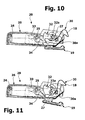
- FIGS 9-11 schematically illustrate the door-lock device 20 in three different conditions; it should be observed that, in these figures, some details of the device are represented transparent, for further clarity.
- Figure 9 represents the device 20 in a condition corresponding to the condition of the outer door closed and locked and the inner door closed and locked. Supposing that, after loading the machine the textile items to be treated, the user closes the doors system. Practically, all the user is required to do is push the outer door 8 in the respective closed condition. During such operation, the outer door 8 pushes the inner door 7 in the respective ajar condition, in particular with the cover 26 of the device 20 that is pressed against the external surface of the inner door 7, also due to the counter action exerted by the spring 11 of figure 4 ; at the end of the operation, the tooth 19 of the device 20 is engaged with the edge of the opening 2a of the cabinet 2.
- the control system of the machine controls the actuation of the door-lock device of the inner door 7.
- the hook of the device first engages the slot 17 of the nosepiece 16 of figure 5 and then the actuator of the device exerts, through the same hook, a traction on the nosepiece 16, and thus on the door 7, up to the respective closed and locked condition, overcoming the reaction force of the spring 11 of figure 4 .
- the inner door 7 is moved away from the outer door 8, and thus the outer surface of the door 7 moves away from the cover 26.
- Figure 10 represents the device 20 in a condition corresponding to the condition of the outer door closed and the inner door ajar.
- the control system of the machine 1 controls the door-lock device of the door 7, described previously, in such a manner that the hook frees the nosepiece 16 of figure 5 .
- the spring 11 of figure 4 pushes the inner door 7 towards the outer door 8, which is closed by means of the device 20; more particularly, an outer surface of the door 7 presses the cover 26 the device 20.
- the door 7 causes an clockwise rotation of the cover 26, up to a position close to the plate 21, represented in figure 10 .
- the appendage 26d of the cover 26 cooperates with the appendage of the catch element 32, causing a clockwise rotation thereof.
- the lower part of the catch element 32 is no longer beneath the peg 27 borne by the handle 19, which can thus be rotated clockwise manually.
- the successive figure 11 illustrates the condition in which the handle 19 was rotated clockwise and the inner door 7, due to the elastic reaction force of the spring 11, continues to exert its pressure on the cover 26.
- the peg 27 pushes against an arm of the rocker element 30 opposite to the tooth 18, thus causing an anticlockwise rotation of the same element 30 therewith: the tooth 18 is thus disengaged from the edge of the opening 2a of the cabinet 2.
- the outer door 8 and the inner door 7 may achieve the respective open conditions.
- the movement in question may be manually accompanied by the user, on the outer door 8, while an automatic opening movement of the inner door 7 is partially or entirely generated due to the action of the spring 11 of figure 4 .
- the present invention has the advantage of allowing the user to have a machine 1 on which he is substantially required to perform only one operation (i.e. only one manoeuvre on the outer door 8) so as to obtain both the closure and the opening of both doors 7 and 8. It shall be observed that, through the configuration outlined for exemplifying purposes, the door-lock device of the inner door 7 does not require any manual actuation means, such as a handle.
- the present invention allows overcoming the drawbacks of the aforementioned prior art and it is suitable to be implemented, alongside according to the example described previously, also according to numerous variants that fall within the same invention concept defined by the claims that follow.
- the door-lock device for the inner door shall preferably be an electrically actuated device, controlled by the control system of the machine, while the door-lock device for the outer door shall preferably be a solely mechanical device, i.e. not requiring electrical actuation.
Landscapes
- Engineering & Computer Science (AREA)
- Textile Engineering (AREA)
- Main Body Construction Of Washing Machines And Laundry Dryers (AREA)
- Treatment Of Fiber Materials (AREA)
Abstract
- an oscillating unit (3,4) including a tub (3) suitable for containing a washing and/or rinsing liquid;
- a cabinet (2) accommodating the oscillating unit (3,4);
- a first opening (3a), obtained on the tub (3) and suitable to allow a user of the machine (1) access into the tub (3);
- a second opening (2a), obtained on the cabinet (2) and suitable to allow the user access to the first opening (3a);
- a first door (7) suitable to close, in particular in a liquid tight manner, the first opening (3a), the first door (3) being able to acquire - with respect to the first opening (3a) - at least an open condition, an ajar condition and a closed and locked condition;
- a second door (8) adapted to close the second opening (2a), the second door (8) being able to acquire - with respect to the second opening (2a) - at least an open condition, a closed condition and a closed and locked condition.
- first closing means (11,16,16a,17a) prearranged to automatically bring the first door (7) from the respective ajar condition to the respective closed and locked condition, and vice versa;
- second closing means (20) prearranged to automatically bring the second door (8) from the respective closed condition to the respective closed and locked condition, and vice versa.
Description
- The present invention refers to a machine for treating textile items, in particular a washing machine, according to the preamble of
claim 1. - It is known that the noise of a washing and/or drying machine may be lowered by reducing the vibrations that are transmitted to the respective cabinet during the operation. For such purpose, the machine may be structurally made in the form of a machine with two doors, i.e. comprising a first inner door, integral with the so-called "oscillating unit", and a second outer door, integral with the cabinet, the two doors not being at contact with respect to each other during the operation of the machine. Such configuration of the machine is functional to eliminate or minimise the points of contact between the cabinet and the oscillating unit and, consequently, to reduce the transmission of vibrations generated at the oscillating unit level to the cabinet. An example of the machines with two doors of the indicated type are described in
EP-A-1319100 andWO 2006/072904 . Both the aforementioned documents describe machines having the inconvenience entailing low comfort in use due to the fact that the user is required to perform two closing operations, successively operating on the two doors. - An aim of the present invention is that of overcoming the drawbacks of the machines with two doors of the prior art, and in particular of those described in the in the cited prior documents. Another aim of the invention is that of providing a machine for treating textile items of the previously indicated type with enhanced comfort in use. Another aim is that of providing a machine of the indicated type characterised by low noise, i.e. by low transmission of vibrations between the oscillating unit and the cabinet of the machine.
- One or more of these aims are attained, according to the present invention, by means of the machine for treating textile items, in particular a washing machine, having the characteristics of the attached claims, whose content forms an integral part of the technical teaching provided herein in relation to the invention.
- In summary, the idea on which the present invention is based is that of providing a machine for treating textile items, in particular a washing machine, having a system of two doors, comprising a first inner door, fixed to the oscillating unit, and a second outer door, fixed to the cabinet, and wherein the comfort in use is enhanced due to the fact that the user of the machine is required to perform only one operation with the aim of opening and/or closing the doors system. In particular, for such purpose, the abovementioned system is provided with first and second means for closing the two doors, configured in such a manner to determine an automatic variation of the condition of one of the two doors ensuing an operation performed on the other of the two doors, such operation being performed by the user or through actuation means of the machine.
- The first closing means are adapted to bring the inner door from a respective ajar condition to a respective closed and locked condition, and vice versa, also causing a movement of the inner door. The second closing means are instead adapted to bring the outer door from a respective closed condition to a respective closed and locked condition, and vice versa. Preferably, the inner door passes from the closed condition to the ajar condition after the passage of the outer door from the respective open condition to the respective closed condition. The outer door passes from the closed condition to the closed and locked condition after the passage of the inner door from the ajar condition to the closed and locked condition; advantageously the outer door passes from the closed and locked condition to the closed condition after the passage of the inner door from the respective closed and locked condition to the respective ajar condition.
- In an embodiment, the first closing means comprise a first door-lock device, having an actuation system which is supplied electrically and controlled through a control system of the machine. The first door-lock device preferably comprises a first movable hooking member, adapted to engage with a closing element borne by the first door, and means for causing, through said actuation system and when the first hooking member and the closing element are mutually engaged, a traction on the first inner door, in order to cause a displacement thereof from the respective ajar condition to the respective closed and locked condition; the abovementioned means preferably comprise the first hooking member, which is mounted in the door-lock device in such a manner to be able to perform both an angular movement, to engage with the closing element of the inner door, and a translation, to cause an angular movement or displacement of the inner door. The second closing means comprise a second door-lock device, preferably but not necessarily actuated only mechanically, i.e. without electric actuation means. This door-lock device may advantageously comprise a locking system switchable between a released condition and a locked condition, the locking system including a movable member which is constrained with respect to the outer door in a displaceable manner between a first and a second position, depending on the position of the inner door; when the inner door is in the respective closed and locked condition, the movable member is in its first position, with the locking system thus being maintained in the respective locked condition; on the contrary, when the inner door is in the respective ajar condition, the movable member is in its second position, with the locking system thus being in the respective released condition.
- In a preferred embodiment the second door-lock device is mounted on the outer door and comprises a second hooking member, having a hooking part suitable to be engaged with respect to a fixed part of the cabinet, and a manual actuation member cooperating with the second hooking member, the manual actuation member being movable to cause the displacement of the second hooking member from an operative position to an inoperative position, where in the operative position the hooking part of the second hooking member is engaged to said fixed part of the cabinet and in the inoperative position the hooking part of the second hooking member is released with respect to said fixed part of the cabinet; the second hooking member is preferably biased towards the respective operative position by a mechanical energy accumulator, such as a spring. In the currently preferred embodiment, the abovementioned locking system of the second door-lock device includes a catch element, adapted to acquire a locked position and a released position, in the locked position the catch element preventing the passage of the second hooking member from its operative position to its inoperative position, and in the released position the catch element allowing the passage of the second hooking member from its operative position to its inoperative position. The abovementioned movable member of the locking system is constrained with respect to the outer door in a displaceable manner between its first and its second position to consequently cause the displacement of the catch element between the respective lock and release positions; the movable member is biased towards the respective first position by a mechanical energy accumulator, such as a spring, and the displacement between the first and the second position of the movable member preferably depends on the contact or absence of contact, respectively, between the movable member and the inner door. The second hooking member, the manual actuation member, the catch element and the movable member preferably rotate around respective axis, which are substantially parallel.
- Further objects, characteristics and advantages of the machine for treating textile items subject of the present invention shall be more apparent from the following detailed description and from the figures attached thereto, strictly provided for exemplifying and non-limiting purposes, wherein:
-
figure 1 is a front view of a washing machine according to the present invention, as it appears when both doors thereof are in closed and locked condition, or when its inner door is in ajar condition and its outer door is in closed condition; -
figure 2 is a front view of the machine offigure 1 , as it appears when both doors thereof are in open condition; -
figure 3 is an axonometric view of the washing machine offigure 1 , in a slightly enlarged scale with respect tofigures 1 and 2 , in a condition similar to that offigure 2 ; -
figures 4 and 5 are detailed views of a first and a second particular offigure 3 , whilefigure 6 is a detailed view of a particular offigure 2 ; -
figure 7 is a partially exploded view of the outer door of the machine offigures 1-3 ; -
figure 8 is an exploded view, in enlarged scale, of a door-lock device of the door offigure 7 ; -
figures 9-11 are schematic representations of the door-lock device offigure 7 , in assembled condition and in three different positions. - In the present description and in the attached claims, the following terms referring to the doors of the machine subject of the invention have the following meanings:
- door "open" condition indicates a condition in which a door of the machine is in such a position not to hinder a respective opening;
- door "closed" condition indicates a condition in which a door of the machine is in a position such to hinder the respective opening, the door being openable through a manual operation of the user;
- door "ajar" condition indicates a condition in which a door is in an intermediate position between those of the door open and door closed, which is proximal to the closed position, in particular with an opening angle smaller than a predetermined value, preferably smaller than about 5° or even more preferably smaller than about 1°;
- "closed and locked" condition indicates a condition in which a door is maintained locked, through a door-lock device, in a position such to hinder the respective opening, the door not being openable through a manual operation of a user.
- It is further specified that in the present description and in the attached drawings reference shall be made only to elements indispensable for the understanding of the invention, without prejudice to the fact that the machine for treating textile items described comprises all the elements known for its normal operation (motor, counterweights, gaskets, pumps, washing agents dispensers, control system, etcetera).
-
Figures 1 - 3 illustrate a machine for treating textile items according to the invention. In the illustrated example, the machine, indicated in its entirety with 1, is awashing machine 1 and comprises acabinet 2, defining a space adapted to accommodate an oscillating unit therein. The aforementioned oscillating unit comprises at least onetub 3 suitable to hold a washing and/or rinsing liquid, particularly water with the possible addition of washing or rinsing agents, accommodating abasket 4 therein adapted to contain items to be treated. The lower part of the cabinet defines an opening having adrawer 5, for example of the type described inEP-A-1462562 , while fixed at the upper part of thecabinet 2 is acontrol panel 6, advantageously of the type described inEP-A-1924000 . Themachine 1 comprises afirst door 7 and asecond door 8, hereinafter also referred to as inner door and outer door, respectively. Theinner door 7 is associated to the oscillating unit and, in particular, to thetub 3, while theouter door 8 is associated to thecabinet 2. Thedoors corresponding openings tub 3 and on thecabinet 2; at least thedoor 7 allows watertight sealing of the respective opening, through suitable seal means, such as an annular gasket mounted peripherally with respect to the opening 3a. - As observable also in
figure 4 , theinner door 7 is connected to thetub 3 by means of a first hinge, indicated in its entirety with 9, so as to allow the opening and the closing of the door itself. In the illustrated non-limiting example, thefirst hinge 9 comprises apin 10 engaged in corresponding seats obtained on thetub 3 and on the inner door 7: in such case, the opening and closing of theinner door 7 occur through rotation of the same around thepin 10. Thehinge 9 comprises aspring 11, mounted substantially coaxial with respect to thepin 10, which is adapted to determine an assisted or automated movement of theinner door 7, once it has been unlocked. Such assisted opening movement is obtained through first abutment means obtained on thespring 11, for example made in form of a pair ofappendages 12, which abut against the outer surface of thetub 3, and second abutment means obtained on thespring 11, for example made in form of acentral protrusion 13, which abut against the inner surface of theinner door 7. - The
outer door 8 is connected to thecabinet 2 by means of a respectivesecond hinge 14, that allows opening and closure thereof. In the illustrated non-limiting example thehinge 14 comprises a pair of guide elements 15 (see alsofigure 7 ), fixed for example by means of screws to the inner surface of theouter door 8, and capable of rotating around a pair of pins constrained inside thecabinet 2, not shown. In order to close and close lock the system of thedoors machine 1 is provided with a system of closing means, comprising: - first closing means, suitable to bring the
inner door 7 from the respective door ajar condition to the door closed and locked condition, and vice versa; - second closing means, suitable to cause the passage of the
outer door 8 from the respective door closed condition to the door closed and locked condition, and vice versa. - In the illustrated embodiment the abovementioned first closing means comprise a closing element or nosepiece, indicated with 16 in
figure 5 , made in which is aslot 17, fixed to the inner surface of theinner door 7, substantially at the end opposite to that hinged to thetub 3, as well as a seat obtained on thetub 3, indicated with 16a infigures 2 and6 , suitable to receive thenosepiece 16, or at least a part thereof, when thedoor 7 is in ajar condition and/or in closed and locked condition. The first closing means also comprise a hooking member, indicated with 17a infigure 6 , for example in form of a hook mounted in movable manner on thetub 3, at theseat 16a. Thehook 17a is configured in such a manner to be engaged in theslot 17, when thedoor 7 is in ajar condition, thence determining the closing and locking of thedoor 7. For such purpose, thehook 17a is part of a door-lock device, not represented in its entirety, which is suitable to acquire at least two positions: an idle position, wherein thehook 17a does not engage theslot 17, and an operative position, in cui thehook 17a engages theslot 17. The door-lock device is configured in such a manner that, following its actuation controlled through the control system of the machine, and with thehook 17a in the abovementioned operative position, the hook itself exerts a traction on theinner door 7, in such a manner that thenosepiece 16 occupies a respective operative position in theseat 16a, thus determining, alongside a movement of theinner door 7, also the passage of the same from the respective ajar condition to the respective closed and locked condition. The change of position of the hook, for performing the abovementioned traction, may be obtained by using a suitable actuation system. In a possible solution, for example thehook 17a and a first electrical actuator, serving to generate the angular movement of the hook itself, are mounted on a slide member, which is movable in a linear manner through a second electrical actuator, so as to generate a translation of the hook which determines the movement of the door and hence its passage to the closed and locked condition. It is however clear to a man skilled in the art that, through a suitable kinematic system, for example based on the use of cam members, the hook may be mounted at theseat 16a in such a manner that its angular movement and its successive translation are obtainable by means of a single electrical actuator; possibly used in this second case may be a silent actuation member, capable of operating as a linear motor and comprising an element, such as a wire, made of shape memory material. - The second closing means comprise a hook element in form of a tooth, indicated with 18 in
figure 5 , suitable to be engaged on the edge of thecabinet 2 which delimits thesecond opening 2a, when thesecond door 8 is in closed condition or closed and locked, and a manual actuation member, represented by ahandle 19, through which the user may manually disengage and open theouter door 8. Thetooth 18 and thehandle 19 are part of a mechanical door-lock device of theouter door 8, indicated with 20 infigure 5 and shown exploded infigures 7 and8 . As observable infigure 7 , theouter door 8 is provided, on the edge thereof opposite to the side provided with thehinge elements 15, of a recessedseat 8a, at which thedevice 20 is mounted, in such a manner that thehandle 19 is partially accessible even when thedoor 8 is closed (see for examplefigure 1 ). With particular reference tofigure 8 , the door-lock device 20 comprises abase plate 21, intended for fixing thedoor 8 onto the inner front, for example by means of through screws, intorespective sleeve formations 22 of theplate 21. Orthogonally rising from the general plane of theplate 21 are twolateral walls 23, defined on which are first andsecond seats plate 21 also has twoorthogonal appendages 21 a, provided with holes in which thepin 25 passes through. Thepin 24 is used for hinging - to the plate 21 - a cover, indicated with 26, if necessary provided with seats for receiving ends of the pin 24 (one of such seats is indicated with 26a). The cover is thus mounted in such a manner to be able to rotate with respect to theplate 21, around the axis represented by thepin 24. Preferably provided for are mechanical means for stopping the angular movement allowed to thecover 26; for such purpose, in the represented example theplate 21 has a further sleeve formation 22a, intended to receive an end portion of a stop screw, not represented, inserted as a through screw into a hole provided for in thecover 26; formed at such hole is a flared seat, indicated with 26b in which the head of the abovementioned stop screw may be positioned. Thecover 26 is provided with aslot 26c, through which thetooth 18 may project outside thedevice 20; in proximity to such slot, thecover 26 has - in its inner part - anappendage 26d, intended to cooperate with an appendage of a catch element, described hereinafter. - The
pin 25 is used for hinging - to the plate 21 - thehandle 19, which - if required - is provided witharms 19a having throughholes 19b. Made in thehandle 19 is a lateral seat 19c, for example in form of a blind hole. Partially inserted into the seat 19c is apeg 27, which is thus substantially parallel to the rotation axis of thehandle 19 represented by thepin 25. In the assembled condition of thedevice 20, an end portion of thepeg 27 projects laterally from thehandle 19 and it is inserted into aslot guide 28 which is formed in a front projection of one of thewalls 23 of the plate. Formed on this projection is a first throughseat 29, for the positioning of thepin 30a of arocker element 30, to which also thetooth 18 belongs. In addition, obtained on the abovementioned projection is a second throughhole 31, adapted to receive thehinge pin 32a of acatch element 32, provided with anappendage 32b intended to cooperate with theappendage 26d of thecover 26. As observable, the rotation axes of thepins rocker element 30 and of thecatch element 32, are substantially parallel to each other and with respect to the rotation axes of the cover (pin 24) and the handle 19 (pin 25). Intended to be mounted on thepin 25 is afirst torsion spring 33, whose end arms respectively abut against the surface above theplate 21 and the inner surface, not shown infigure 8 , of thecover 26. Thespring 33 is thus operative to cause an anticlockwise rotation of thecover 26, i.e. in a diverged position with respect to theplate 21, whose maximum limit is determined by the previously mentioned stop means; by exerting a pressure on thecover 26 such to overcome the elastic reaction of thespring 33 it is possible to bring the cover itself to a position closer to theplate 21. Furthermore, intended to be mounted on thepin 25 is asecond torsion spring 34, having an end arm cooperating with therocker element 30, so as to cause the latter to rotate clockwise; the opposite end arm of thespring 34 instead cooperates with thecatch element 32, so as to cause the latter to rotate anticlockwise. - In the assembled condition of the
device 20, thepeg 27 borne by thehandle 19 cooperates with therocker element 30, so as to determine a rotation such that thetooth 18 moves to a position that allows the manual opening of thesecond door 8, by rotating the handle clockwise. Thecatch element 32 has instead the function to become operatively interposed between thepeg 27 and thebalance element 30 or, more precisely, the general function to take off the rotational degree of freedom from thehandle 19. Thecatch element 32 is automatically deactivated when theinner door 7 exerts a pressure on the cover 26: in particular, the pressure exerted by thedoor 7 causes a clockwise rotation of thecover 26, which thus nears theplate 21. In this manner, theappendage 26c of thecover 26 ends up in abutment against theappendage 32b of the catch element, which is thus caused to rotate clockwise, up to a position in which the catch element no longer represents a constraint for the movement of thepeg 27, and thus thehandle 19, and hence therocker element 30. -
Figures 9-11 schematically illustrate the door-lock device 20 in three different conditions; it should be observed that, in these figures, some details of the device are represented transparent, for further clarity. -
Figure 9 represents thedevice 20 in a condition corresponding to the condition of the outer door closed and locked and the inner door closed and locked. Supposing that, after loading the machine the textile items to be treated, the user closes the doors system. Practically, all the user is required to do is push theouter door 8 in the respective closed condition. During such operation, theouter door 8 pushes theinner door 7 in the respective ajar condition, in particular with thecover 26 of thedevice 20 that is pressed against the external surface of theinner door 7, also due to the counter action exerted by thespring 11 offigure 4 ; at the end of the operation, thetooth 19 of thedevice 20 is engaged with the edge of theopening 2a of thecabinet 2. Then, the user starts themachine 1 and/or starts the desired washing cycle, operating on thecontrol panel 6. The control system of the machine controls the actuation of the door-lock device of theinner door 7. Substantially, as mentioned previously, the hook of the device first engages theslot 17 of thenosepiece 16 offigure 5 and then the actuator of the device exerts, through the same hook, a traction on thenosepiece 16, and thus on thedoor 7, up to the respective closed and locked condition, overcoming the reaction force of thespring 11 offigure 4 . In this manner, theinner door 7 is moved away from theouter door 8, and thus the outer surface of thedoor 7 moves away from thecover 26. Due to the action of thespring 33 offigure 8 , the cover rotates anticlockwise, around the axis represented by thepin 24 and in this manner also thecatch element 32 is free to rotate anticlockwise, due to the action of thespring 34, moving to the position observable infigure 9 . In this condition, the lower part of thecatch element 32 is fitted beneath thepeg 27, in such a manner that thehandle 19 cannot move anticlockwise around therespective pin 25. Therefore, in other words, even if one were to operate on thehandle 19, it is not possible to rotate thebalance element 30 clockwise, and thus disengage thetooth 19 from the edge of theopening 2a of thecabinet 2. -
Figure 10 represents thedevice 20 in a condition corresponding to the condition of the outer door closed and the inner door ajar. For such purpose, at the end of the washing cycle mentioned above, the control system of themachine 1 controls the door-lock device of thedoor 7, described previously, in such a manner that the hook frees thenosepiece 16 offigure 5 . In this condition thespring 11 offigure 4 pushes theinner door 7 towards theouter door 8, which is closed by means of thedevice 20; more particularly, an outer surface of thedoor 7 presses thecover 26 thedevice 20. Given that the elastic reaction ofspring 11 is greater with respect to the reaction force ofsprings door 7 causes an clockwise rotation of thecover 26, up to a position close to theplate 21, represented infigure 10 . In this step (seefigure 8 ) theappendage 26d of thecover 26 cooperates with the appendage of thecatch element 32, causing a clockwise rotation thereof. In this manner, the lower part of thecatch element 32 is no longer beneath thepeg 27 borne by thehandle 19, which can thus be rotated clockwise manually. - The successive
figure 11 illustrates the condition in which thehandle 19 was rotated clockwise and theinner door 7, due to the elastic reaction force of thespring 11, continues to exert its pressure on thecover 26. In this manner, thepeg 27 pushes against an arm of therocker element 30 opposite to thetooth 18, thus causing an anticlockwise rotation of thesame element 30 therewith: thetooth 18 is thus disengaged from the edge of theopening 2a of thecabinet 2. At this point, theouter door 8 and theinner door 7 may achieve the respective open conditions. The movement in question may be manually accompanied by the user, on theouter door 8, while an automatic opening movement of theinner door 7 is partially or entirely generated due to the action of thespring 11 offigure 4 . - As observable, the present invention has the advantage of allowing the user to have a
machine 1 on which he is substantially required to perform only one operation (i.e. only one manoeuvre on the outer door 8) so as to obtain both the closure and the opening of bothdoors inner door 7 does not require any manual actuation means, such as a handle. - In summary, the operation of closing the doors system provides for the following sequence of steps:
- a) closure of the
outer door 8 through a manual action of the user who, pushing theouter door 8, causes the latter to draw theinner door 7 in its movement; at the end of such step, thetooth 18 engages the wall of thecabinet 2, and the inner door 7 - contacting the outer door 8 - automatically achieves the respective door ajar condition; - b) locking, through an automatic action of the
machine 1, theinner door 7, by means of actuation of the respective door-lock device, whose hook is engaged in theslot 17 and causes thenosepiece 16 to occupy the respective operative position in theseat 16a; at the end of such step, theouter door 8 automatically achieves the respective closed and locked condition, by means of thedevice 20, whosecatch element 32 hinders the movement of thehandle 19. - The operation of opening the doors system provides for the following sequence of steps:
- a) unlocking the
inner door 7 through the automatic action of thewashing machine 1, and specifically its control system which controls the door-lock device of thedoor 7 such that the respective hook is disengaged from theslot 17; at the end of such step theinner door 7 automatically achieves the door ajar condition, by means of the action of thespring 11, and theouter door 8 automatically achieves the door closed condition, theinner door 7 contacting the rear surface of thecover 26; - b) opening the
outer door 8 through the manual action of the user who operates on thehandle 19; at the end of such step, both doors are in open condition, the opening of theinner door 7 being ensured or facilitated by thespring 11. - The present invention allows overcoming the drawbacks of the aforementioned prior art and it is suitable to be implemented, alongside according to the example described previously, also according to numerous variants that fall within the same invention concept defined by the claims that follow.
- The specific configuration of the door-lock devices for the
inner door 7 and theouter door 8 may obviously vary with respect to the one described or illustrated previously, being freely useable by the man skilled in the art in the form deemed most suitable for the specific application, without prejudice to the functionalities described previously. In the preferred embodiment, the door-lock device for the inner door shall preferably be an electrically actuated device, controlled by the control system of the machine, while the door-lock device for the outer door shall preferably be a solely mechanical device, i.e. not requiring electrical actuation.
Claims (10)
- A machine for treating textile items, in particular a washing machine, comprising:- an oscillating unit (3, 4) including a tub (3) suitable for containing a washing and/or rinsing liquid;- a cabinet (2) housing the oscillating unit (3, 4);- a first opening (3a), obtained in the tub (3) and suitable for allowing a user of the machine to have access to the inside of the tub (3);- a second opening (2a), obtained in the cabinet (2) and suitable for allowing the user to have access to the first opening (3a);- a first door (7) suitable for closing the first opening (3a), in particular in a watertight manner, the first door (3) being able to take at least one open condition, one ajar condition and one closed and locked condition relative to the first opening (3a);- a second door (8) suitable for closing the second opening (2a), the second door (8) being able to take at least one open condition, one closed condition and one closed and locked condition relative to the second opening (2a);characterized by further comprising:- first closing means (11, 16, 16a, 17a) prearranged to bring in an automated manner the first door (7) from the respective ajar condition to the respective closed and locked condition, and vice versa;- second closing means (20) prearranged to cause in an automated manner passing of the second door (8) from the respective closed condition to the respective closed and locked condition, and vice versa.
- The machine according to claim 1, wherein the second closing means (20) are configured such that the second door (8) passes from the respective closed condition to the respective closed and locked condition in consequence of a passing of the first door (7) from the respective ajar condition to the respective closed and locked condition.
- The machine according to claim 1 or 2, wherein the first and the second doors (7, 8) are configured and positioned such that the first door (7) passes from the respective open condition to the respective ajar condition in consequence of a passing of the second door (8) from the respective open condition to the respective closed condition.
- The machine according to claim 2, wherein the second closing means (20) are also configured such that the second door (8) passes from the respective closed and locked condition to the respective closed condition in consequence of a passing of the first door (7) from the respective closed and locked condition to the respective ajar condition.
- The machine according to at least one of the preceding claims, wherein the first closing means comprises a first door-lock device (16a, 17a) having an actuation system which is electrically supplied and controlled through a control system (6) of the machine (1).
- The machine according to at least one of the preceding claims, wherein the second closing means comprises a second door-lock device (20) being mechanically actuated or free of electric actuation means.
- The machine according to claim 5, wherein the first door-lock device comprises a first movable hooking member (17a), adapted to engage with a closing element (16) carried by the first door (7), and means for causing, through said actuation system and when the first hooking member (17a) and the closing element (16) are mutually engaged, a traction on the first door (7), in order to cause a displacement thereof from the respective ajar condition to the respective closed and locked condition.
- The machine according to claim 6, wherein the second door-lock device (20) comprises a locking system (26, 32), which is switchable between a released position and a locked position, the locking system (26, 32) including a movable member (26) which is bound relative to the second door (8) to be displaceable between a first and a second position, which correspond to the above said released and locked positions, the position of the movable member (26) depending upon the position of the first door (7).
- The machine according to claim 6, wherein the second door-lock device (20) comprises a second hooking member (30), having an hooking part (19) adapted to engage with respect to a fixed part of the cabinet (2), and a manual actuation member (19, 27) cooperating with the second hooking member (30), and wherein the locking system (26, 32) comprises a catch element (32) which is displaceable by means of the movable member (26), where in particular the second hooking member (30), the manual actuation member (19, 27), the catch element (32) and the movable member (26) are rotatable around respective axes (30a, 25, 32a, 24), these axes being substantially parallel to each other.
- The machine according to one or more of the preceding claims, wherein the first closing means (11, 16, 16a) include a mechanical energy accumulator (11), such as a spring, for constantly biasing the first door (7) toward the respective open condition.
Applications Claiming Priority (1)
| Application Number | Priority Date | Filing Date | Title |
|---|---|---|---|
| ITTO2008A000513A IT1390904B1 (en) | 2008-07-01 | 2008-07-01 | MACHINE FOR THE TREATMENT OF TEXTILE HEADS, IN PARTICULAR A WASHING MACHINE |
Publications (2)
| Publication Number | Publication Date |
|---|---|
| EP2141277A1 true EP2141277A1 (en) | 2010-01-06 |
| EP2141277B1 EP2141277B1 (en) | 2014-03-19 |
Family
ID=40655284
Family Applications (1)
| Application Number | Title | Priority Date | Filing Date |
|---|---|---|---|
| EP09163078.0A Not-in-force EP2141277B1 (en) | 2008-07-01 | 2009-06-18 | Machine for treating textile items, in particular a washing machine |
Country Status (2)
| Country | Link |
|---|---|
| EP (1) | EP2141277B1 (en) |
| IT (1) | IT1390904B1 (en) |
Cited By (13)
| Publication number | Priority date | Publication date | Assignee | Title |
|---|---|---|---|---|
| US9101258B2 (en) | 2013-04-16 | 2015-08-11 | Whirlpool Corporation | Multiple compartment dishwasher with interior and exterior closure elements |
| WO2016119831A1 (en) * | 2015-01-28 | 2016-08-04 | Arcelik Anonim Sirketi | Laundry machine front door handle with an improved mounting mechanism |
| WO2017020959A1 (en) * | 2015-08-06 | 2017-02-09 | Arcelik Anonim Sirketi | Laundry treatment machine with a front door handle mounting mechanism |
| US9999337B2 (en) | 2011-11-23 | 2018-06-19 | Whirlpool Corporation | System for establishing communication between a user interface and a controller of a dishwasher |
| US10004379B2 (en) | 2011-11-23 | 2018-06-26 | Whirlpool Corporation | Dishwasher with transforming door |
| EP3272925A4 (en) * | 2015-03-20 | 2018-08-15 | LG Electronics Inc. | Washing machine |
| CN111663297A (en) * | 2019-03-07 | 2020-09-15 | 青岛海尔滚筒洗衣机有限公司 | A washing machine and its control method |
| WO2020253593A1 (en) * | 2019-06-18 | 2020-12-24 | 青岛海尔滚筒洗衣机有限公司 | Door body pop-out assembly and garment processing device |
| WO2020253594A1 (en) * | 2019-06-18 | 2020-12-24 | 青岛海尔滚筒洗衣机有限公司 | Door member ejection assembly, installation method, and laundry processing apparatus |
| CN112144249A (en) * | 2019-06-27 | 2020-12-29 | 博西华电器(江苏)有限公司 | Laundry appliance |
| DE102014205224B4 (en) * | 2013-03-21 | 2021-02-11 | Lg Electronics Inc. | Laundry treating device |
| CN112391811A (en) * | 2019-08-13 | 2021-02-23 | 惠而浦有限公司 | Door-in-door design |
| US11885060B2 (en) | 2019-12-16 | 2024-01-30 | Lg Electronics Inc. | Laundry device |
Families Citing this family (1)
| Publication number | Priority date | Publication date | Assignee | Title |
|---|---|---|---|---|
| WO2016182263A1 (en) * | 2015-05-08 | 2016-11-17 | 엘지전자 주식회사 | Washing device |
Citations (6)
| Publication number | Priority date | Publication date | Assignee | Title |
|---|---|---|---|---|
| GB979170A (en) * | 1962-04-05 | 1965-01-01 | Constructa Werke Gmbh | Improvements relating to washing and spin-drying machines |
| JP2003093789A (en) * | 2001-09-21 | 2003-04-02 | Nakagawa Electric Ind Co Ltd | Inner lid locking device for spin-drying tub |
| EP1319100A1 (en) | 2000-09-16 | 2003-06-18 | Dyson Limited | Laundry appliance |
| EP1462562A1 (en) | 2003-03-28 | 2004-09-29 | Merloni Elettrodomestici S.p.A. | A laundry washing and /or drying machine, in particular of the front loading type, with lower housing |
| WO2006072904A1 (en) | 2005-01-03 | 2006-07-13 | Arcelik Anonim Sirketi | A washer/dryer |
| EP1924000A2 (en) | 2006-11-16 | 2008-05-21 | Indesit Company S.p.A. | Household appliance with touch-type user control devices |
-
2008
- 2008-07-01 IT ITTO2008A000513A patent/IT1390904B1/en active
-
2009
- 2009-06-18 EP EP09163078.0A patent/EP2141277B1/en not_active Not-in-force
Patent Citations (6)
| Publication number | Priority date | Publication date | Assignee | Title |
|---|---|---|---|---|
| GB979170A (en) * | 1962-04-05 | 1965-01-01 | Constructa Werke Gmbh | Improvements relating to washing and spin-drying machines |
| EP1319100A1 (en) | 2000-09-16 | 2003-06-18 | Dyson Limited | Laundry appliance |
| JP2003093789A (en) * | 2001-09-21 | 2003-04-02 | Nakagawa Electric Ind Co Ltd | Inner lid locking device for spin-drying tub |
| EP1462562A1 (en) | 2003-03-28 | 2004-09-29 | Merloni Elettrodomestici S.p.A. | A laundry washing and /or drying machine, in particular of the front loading type, with lower housing |
| WO2006072904A1 (en) | 2005-01-03 | 2006-07-13 | Arcelik Anonim Sirketi | A washer/dryer |
| EP1924000A2 (en) | 2006-11-16 | 2008-05-21 | Indesit Company S.p.A. | Household appliance with touch-type user control devices |
Cited By (17)
| Publication number | Priority date | Publication date | Assignee | Title |
|---|---|---|---|---|
| US9999337B2 (en) | 2011-11-23 | 2018-06-19 | Whirlpool Corporation | System for establishing communication between a user interface and a controller of a dishwasher |
| US10004379B2 (en) | 2011-11-23 | 2018-06-26 | Whirlpool Corporation | Dishwasher with transforming door |
| DE102014205224B4 (en) * | 2013-03-21 | 2021-02-11 | Lg Electronics Inc. | Laundry treating device |
| US9101258B2 (en) | 2013-04-16 | 2015-08-11 | Whirlpool Corporation | Multiple compartment dishwasher with interior and exterior closure elements |
| WO2016119831A1 (en) * | 2015-01-28 | 2016-08-04 | Arcelik Anonim Sirketi | Laundry machine front door handle with an improved mounting mechanism |
| EP3272925A4 (en) * | 2015-03-20 | 2018-08-15 | LG Electronics Inc. | Washing machine |
| EP3272926A4 (en) * | 2015-03-20 | 2018-10-31 | LG Electronics Inc. | Washing machine |
| WO2017020959A1 (en) * | 2015-08-06 | 2017-02-09 | Arcelik Anonim Sirketi | Laundry treatment machine with a front door handle mounting mechanism |
| CN111663297A (en) * | 2019-03-07 | 2020-09-15 | 青岛海尔滚筒洗衣机有限公司 | A washing machine and its control method |
| CN111663297B (en) * | 2019-03-07 | 2023-05-23 | 青岛海尔洗涤电器有限公司 | Washing machine and control method thereof |
| WO2020253593A1 (en) * | 2019-06-18 | 2020-12-24 | 青岛海尔滚筒洗衣机有限公司 | Door body pop-out assembly and garment processing device |
| WO2020253594A1 (en) * | 2019-06-18 | 2020-12-24 | 青岛海尔滚筒洗衣机有限公司 | Door member ejection assembly, installation method, and laundry processing apparatus |
| CN112144249A (en) * | 2019-06-27 | 2020-12-29 | 博西华电器(江苏)有限公司 | Laundry appliance |
| CN112144249B (en) * | 2019-06-27 | 2023-11-17 | 博西华电器(江苏)有限公司 | laundry equipment |
| CN112391811A (en) * | 2019-08-13 | 2021-02-23 | 惠而浦有限公司 | Door-in-door design |
| US11459694B2 (en) * | 2019-08-13 | 2022-10-04 | Whirlpool Corporation | Door-in-door design |
| US11885060B2 (en) | 2019-12-16 | 2024-01-30 | Lg Electronics Inc. | Laundry device |
Also Published As
| Publication number | Publication date |
|---|---|
| IT1390904B1 (en) | 2011-10-19 |
| EP2141277B1 (en) | 2014-03-19 |
| ITTO20080513A1 (en) | 2010-01-02 |
Similar Documents
| Publication | Publication Date | Title |
|---|---|---|
| EP2141277B1 (en) | Machine for treating textile items, in particular a washing machine | |
| RU2376435C2 (en) | Locking device for domestic appliance | |
| EP3642434B1 (en) | Appliance door latch system with pre-latching catch alignment system and appliance with said door latch system | |
| RU2506361C2 (en) | Washing machine | |
| KR101053624B1 (en) | Clothing processing device | |
| US7347460B2 (en) | Latch device for a door of an electric household appliance in particular a dishwashing machine | |
| US12398582B2 (en) | Domestic electrical appliance and door latch therefor | |
| US9567783B2 (en) | Self-resettable door locking device for an electric household appliance, in particular a dishwasher | |
| US10119219B2 (en) | Laundry treating apparatus | |
| KR101699118B1 (en) | Door lock device with an opening button | |
| KR101463514B1 (en) | Door-lock Apparatus of Push and Push | |
| US11819177B2 (en) | Resettable door locking device for an electric household appliance, in particular a dishwasher, and electric household appliance provided therewith | |
| KR100954077B1 (en) | The door-lock device with a dual locker | |
| US6653581B2 (en) | Device for closing the door of an electric household appliance, in particular a dishwahser | |
| RU2649941C1 (en) | Linen processing device | |
| KR20130019246A (en) | A handle apparatus for a sliding door | |
| AU2012321061B2 (en) | Device for unlocking a door | |
| CN101666028B (en) | Locking device for closing cap of washing machine | |
| CN223739196U (en) | Door opener and electrical equipment | |
| JP5145183B2 (en) | Door lock device | |
| CN114941478A (en) | Door lock for a household appliance and household appliance comprising such a door lock | |
| US12601203B2 (en) | Household appliance with emergency opening and emergency opening device | |
| EP2458057B1 (en) | Appliance handle assembly and method for mounting such assembly to an appliance | |
| US20210230907A1 (en) | Door-lock device for household appliances and household appliance comprising said device | |
| KR102496579B1 (en) | Laundry Treating Apparatus |
Legal Events
| Date | Code | Title | Description |
|---|---|---|---|
| PUAI | Public reference made under article 153(3) epc to a published international application that has entered the european phase |
Free format text: ORIGINAL CODE: 0009012 |
|
| 17P | Request for examination filed |
Effective date: 20091021 |
|
| AK | Designated contracting states |
Kind code of ref document: A1 Designated state(s): AT BE BG CH CY CZ DE DK EE ES FI FR GB GR HR HU IE IS IT LI LT LU LV MC MK MT NL NO PL PT RO SE SI SK TR |
|
| GRAP | Despatch of communication of intention to grant a patent |
Free format text: ORIGINAL CODE: EPIDOSNIGR1 |
|
| INTG | Intention to grant announced |
Effective date: 20131010 |
|
| RIN1 | Information on inventor provided before grant (corrected) |
Inventor name: BONGINI, DINO Inventor name: NOCERA, FORTUNATO |
|
| GRAS | Grant fee paid |
Free format text: ORIGINAL CODE: EPIDOSNIGR3 |
|
| GRAA | (expected) grant |
Free format text: ORIGINAL CODE: 0009210 |
|
| AK | Designated contracting states |
Kind code of ref document: B1 Designated state(s): AT BE BG CH CY CZ DE DK EE ES FI FR GB GR HR HU IE IS IT LI LT LU LV MC MK MT NL NO PL PT RO SE SI SK TR |
|
| REG | Reference to a national code |
Ref country code: GB Ref legal event code: FG4D |
|
| REG | Reference to a national code |
Ref country code: CH Ref legal event code: EP |
|
| REG | Reference to a national code |
Ref country code: IE Ref legal event code: FG4D |
|
| REG | Reference to a national code |
Ref country code: AT Ref legal event code: REF Ref document number: 657772 Country of ref document: AT Kind code of ref document: T Effective date: 20140415 |
|
| REG | Reference to a national code |
Ref country code: DE Ref legal event code: R096 Ref document number: 602009022559 Country of ref document: DE Effective date: 20140430 |
|
| PG25 | Lapsed in a contracting state [announced via postgrant information from national office to epo] |
Ref country code: LT Free format text: LAPSE BECAUSE OF FAILURE TO SUBMIT A TRANSLATION OF THE DESCRIPTION OR TO PAY THE FEE WITHIN THE PRESCRIBED TIME-LIMIT Effective date: 20140319 Ref country code: NO Free format text: LAPSE BECAUSE OF FAILURE TO SUBMIT A TRANSLATION OF THE DESCRIPTION OR TO PAY THE FEE WITHIN THE PRESCRIBED TIME-LIMIT Effective date: 20140619 |
|
| REG | Reference to a national code |
Ref country code: NL Ref legal event code: VDEP Effective date: 20140319 |
|
| REG | Reference to a national code |
Ref country code: AT Ref legal event code: MK05 Ref document number: 657772 Country of ref document: AT Kind code of ref document: T Effective date: 20140319 |
|
| REG | Reference to a national code |
Ref country code: LT Ref legal event code: MG4D |
|
| PG25 | Lapsed in a contracting state [announced via postgrant information from national office to epo] |
Ref country code: SE Free format text: LAPSE BECAUSE OF FAILURE TO SUBMIT A TRANSLATION OF THE DESCRIPTION OR TO PAY THE FEE WITHIN THE PRESCRIBED TIME-LIMIT Effective date: 20140319 Ref country code: CY Free format text: LAPSE BECAUSE OF FAILURE TO SUBMIT A TRANSLATION OF THE DESCRIPTION OR TO PAY THE FEE WITHIN THE PRESCRIBED TIME-LIMIT Effective date: 20140319 Ref country code: FI Free format text: LAPSE BECAUSE OF FAILURE TO SUBMIT A TRANSLATION OF THE DESCRIPTION OR TO PAY THE FEE WITHIN THE PRESCRIBED TIME-LIMIT Effective date: 20140319 |
|
| PG25 | Lapsed in a contracting state [announced via postgrant information from national office to epo] |
Ref country code: HR Free format text: LAPSE BECAUSE OF FAILURE TO SUBMIT A TRANSLATION OF THE DESCRIPTION OR TO PAY THE FEE WITHIN THE PRESCRIBED TIME-LIMIT Effective date: 20140319 Ref country code: LV Free format text: LAPSE BECAUSE OF FAILURE TO SUBMIT A TRANSLATION OF THE DESCRIPTION OR TO PAY THE FEE WITHIN THE PRESCRIBED TIME-LIMIT Effective date: 20140319 |
|
| PG25 | Lapsed in a contracting state [announced via postgrant information from national office to epo] |
Ref country code: RO Free format text: LAPSE BECAUSE OF FAILURE TO SUBMIT A TRANSLATION OF THE DESCRIPTION OR TO PAY THE FEE WITHIN THE PRESCRIBED TIME-LIMIT Effective date: 20140319 Ref country code: EE Free format text: LAPSE BECAUSE OF FAILURE TO SUBMIT A TRANSLATION OF THE DESCRIPTION OR TO PAY THE FEE WITHIN THE PRESCRIBED TIME-LIMIT Effective date: 20140319 Ref country code: BG Free format text: LAPSE BECAUSE OF FAILURE TO SUBMIT A TRANSLATION OF THE DESCRIPTION OR TO PAY THE FEE WITHIN THE PRESCRIBED TIME-LIMIT Effective date: 20140619 Ref country code: CZ Free format text: LAPSE BECAUSE OF FAILURE TO SUBMIT A TRANSLATION OF THE DESCRIPTION OR TO PAY THE FEE WITHIN THE PRESCRIBED TIME-LIMIT Effective date: 20140319 Ref country code: NL Free format text: LAPSE BECAUSE OF FAILURE TO SUBMIT A TRANSLATION OF THE DESCRIPTION OR TO PAY THE FEE WITHIN THE PRESCRIBED TIME-LIMIT Effective date: 20140319 Ref country code: IS Free format text: LAPSE BECAUSE OF FAILURE TO SUBMIT A TRANSLATION OF THE DESCRIPTION OR TO PAY THE FEE WITHIN THE PRESCRIBED TIME-LIMIT Effective date: 20140719 Ref country code: BE Free format text: LAPSE BECAUSE OF FAILURE TO SUBMIT A TRANSLATION OF THE DESCRIPTION OR TO PAY THE FEE WITHIN THE PRESCRIBED TIME-LIMIT Effective date: 20140319 |
|
| PG25 | Lapsed in a contracting state [announced via postgrant information from national office to epo] |
Ref country code: AT Free format text: LAPSE BECAUSE OF FAILURE TO SUBMIT A TRANSLATION OF THE DESCRIPTION OR TO PAY THE FEE WITHIN THE PRESCRIBED TIME-LIMIT Effective date: 20140319 Ref country code: ES Free format text: LAPSE BECAUSE OF FAILURE TO SUBMIT A TRANSLATION OF THE DESCRIPTION OR TO PAY THE FEE WITHIN THE PRESCRIBED TIME-LIMIT Effective date: 20140319 Ref country code: PL Free format text: LAPSE BECAUSE OF FAILURE TO SUBMIT A TRANSLATION OF THE DESCRIPTION OR TO PAY THE FEE WITHIN THE PRESCRIBED TIME-LIMIT Effective date: 20140319 Ref country code: SK Free format text: LAPSE BECAUSE OF FAILURE TO SUBMIT A TRANSLATION OF THE DESCRIPTION OR TO PAY THE FEE WITHIN THE PRESCRIBED TIME-LIMIT Effective date: 20140319 |
|
| REG | Reference to a national code |
Ref country code: DE Ref legal event code: R097 Ref document number: 602009022559 Country of ref document: DE |
|
| PG25 | Lapsed in a contracting state [announced via postgrant information from national office to epo] |
Ref country code: PT Free format text: LAPSE BECAUSE OF FAILURE TO SUBMIT A TRANSLATION OF THE DESCRIPTION OR TO PAY THE FEE WITHIN THE PRESCRIBED TIME-LIMIT Effective date: 20140721 |
|
| PLBE | No opposition filed within time limit |
Free format text: ORIGINAL CODE: 0009261 |
|
| STAA | Information on the status of an ep patent application or granted ep patent |
Free format text: STATUS: NO OPPOSITION FILED WITHIN TIME LIMIT |
|
| PG25 | Lapsed in a contracting state [announced via postgrant information from national office to epo] |
Ref country code: LU Free format text: LAPSE BECAUSE OF FAILURE TO SUBMIT A TRANSLATION OF THE DESCRIPTION OR TO PAY THE FEE WITHIN THE PRESCRIBED TIME-LIMIT Effective date: 20140618 Ref country code: DK Free format text: LAPSE BECAUSE OF FAILURE TO SUBMIT A TRANSLATION OF THE DESCRIPTION OR TO PAY THE FEE WITHIN THE PRESCRIBED TIME-LIMIT Effective date: 20140319 Ref country code: MC Free format text: LAPSE BECAUSE OF FAILURE TO SUBMIT A TRANSLATION OF THE DESCRIPTION OR TO PAY THE FEE WITHIN THE PRESCRIBED TIME-LIMIT Effective date: 20140319 |
|
| REG | Reference to a national code |
Ref country code: CH Ref legal event code: PL |
|
| 26N | No opposition filed |
Effective date: 20141222 |
|
| REG | Reference to a national code |
Ref country code: IE Ref legal event code: MM4A |
|
| REG | Reference to a national code |
Ref country code: DE Ref legal event code: R097 Ref document number: 602009022559 Country of ref document: DE Effective date: 20141222 |
|
| PG25 | Lapsed in a contracting state [announced via postgrant information from national office to epo] |
Ref country code: LI Free format text: LAPSE BECAUSE OF NON-PAYMENT OF DUE FEES Effective date: 20140630 Ref country code: CH Free format text: LAPSE BECAUSE OF NON-PAYMENT OF DUE FEES Effective date: 20140630 Ref country code: IE Free format text: LAPSE BECAUSE OF NON-PAYMENT OF DUE FEES Effective date: 20140618 |
|
| REG | Reference to a national code |
Ref country code: FR Ref legal event code: PLFP Year of fee payment: 7 |
|
| PG25 | Lapsed in a contracting state [announced via postgrant information from national office to epo] |
Ref country code: SI Free format text: LAPSE BECAUSE OF FAILURE TO SUBMIT A TRANSLATION OF THE DESCRIPTION OR TO PAY THE FEE WITHIN THE PRESCRIBED TIME-LIMIT Effective date: 20140319 |
|
| PG25 | Lapsed in a contracting state [announced via postgrant information from national office to epo] |
Ref country code: MT Free format text: LAPSE BECAUSE OF FAILURE TO SUBMIT A TRANSLATION OF THE DESCRIPTION OR TO PAY THE FEE WITHIN THE PRESCRIBED TIME-LIMIT Effective date: 20140319 |
|
| REG | Reference to a national code |
Ref country code: FR Ref legal event code: PLFP Year of fee payment: 8 |
|
| PG25 | Lapsed in a contracting state [announced via postgrant information from national office to epo] |
Ref country code: GR Free format text: LAPSE BECAUSE OF FAILURE TO SUBMIT A TRANSLATION OF THE DESCRIPTION OR TO PAY THE FEE WITHIN THE PRESCRIBED TIME-LIMIT Effective date: 20140620 |
|
| PG25 | Lapsed in a contracting state [announced via postgrant information from national office to epo] |
Ref country code: HU Free format text: LAPSE BECAUSE OF FAILURE TO SUBMIT A TRANSLATION OF THE DESCRIPTION OR TO PAY THE FEE WITHIN THE PRESCRIBED TIME-LIMIT; INVALID AB INITIO Effective date: 20090618 Ref country code: TR Free format text: LAPSE BECAUSE OF FAILURE TO SUBMIT A TRANSLATION OF THE DESCRIPTION OR TO PAY THE FEE WITHIN THE PRESCRIBED TIME-LIMIT Effective date: 20140319 |
|
| REG | Reference to a national code |
Ref country code: FR Ref legal event code: PLFP Year of fee payment: 9 |
|
| PGFP | Annual fee paid to national office [announced via postgrant information from national office to epo] |
Ref country code: FR Payment date: 20170720 Year of fee payment: 12 |
|
| PGFP | Annual fee paid to national office [announced via postgrant information from national office to epo] |
Ref country code: IT Payment date: 20170619 Year of fee payment: 9 |
|
| PG25 | Lapsed in a contracting state [announced via postgrant information from national office to epo] |
Ref country code: MK Free format text: LAPSE BECAUSE OF FAILURE TO SUBMIT A TRANSLATION OF THE DESCRIPTION OR TO PAY THE FEE WITHIN THE PRESCRIBED TIME-LIMIT Effective date: 20140319 |
|
| PGFP | Annual fee paid to national office [announced via postgrant information from national office to epo] |
Ref country code: GB Payment date: 20180403 Year of fee payment: 10 |
|
| REG | Reference to a national code |
Ref country code: DE Ref legal event code: R119 Ref document number: 602009022559 Country of ref document: DE |
|
| PG25 | Lapsed in a contracting state [announced via postgrant information from national office to epo] |
Ref country code: DE Free format text: LAPSE BECAUSE OF NON-PAYMENT OF DUE FEES Effective date: 20190101 Ref country code: IT Free format text: LAPSE BECAUSE OF NON-PAYMENT OF DUE FEES Effective date: 20180618 Ref country code: FR Free format text: LAPSE BECAUSE OF NON-PAYMENT OF DUE FEES Effective date: 20180630 |
|
| GBPC | Gb: european patent ceased through non-payment of renewal fee |
Effective date: 20190618 |
|
| PG25 | Lapsed in a contracting state [announced via postgrant information from national office to epo] |
Ref country code: GB Free format text: LAPSE BECAUSE OF NON-PAYMENT OF DUE FEES Effective date: 20190618 |