EP2141255A1 - Improved corrosion inhibiting structure - Google Patents
Improved corrosion inhibiting structure Download PDFInfo
- Publication number
- EP2141255A1 EP2141255A1 EP08159783A EP08159783A EP2141255A1 EP 2141255 A1 EP2141255 A1 EP 2141255A1 EP 08159783 A EP08159783 A EP 08159783A EP 08159783 A EP08159783 A EP 08159783A EP 2141255 A1 EP2141255 A1 EP 2141255A1
- Authority
- EP
- European Patent Office
- Prior art keywords
- metal member
- metal
- vehicle according
- steel
- alloy
- Prior art date
- Legal status (The legal status is an assumption and is not a legal conclusion. Google has not performed a legal analysis and makes no representation as to the accuracy of the status listed.)
- Granted
Links
Images



Classifications
-
- C—CHEMISTRY; METALLURGY
- C23—COATING METALLIC MATERIAL; COATING MATERIAL WITH METALLIC MATERIAL; CHEMICAL SURFACE TREATMENT; DIFFUSION TREATMENT OF METALLIC MATERIAL; COATING BY VACUUM EVAPORATION, BY SPUTTERING, BY ION IMPLANTATION OR BY CHEMICAL VAPOUR DEPOSITION, IN GENERAL; INHIBITING CORROSION OF METALLIC MATERIAL OR INCRUSTATION IN GENERAL
- C23C—COATING METALLIC MATERIAL; COATING MATERIAL WITH METALLIC MATERIAL; SURFACE TREATMENT OF METALLIC MATERIAL BY DIFFUSION INTO THE SURFACE, BY CHEMICAL CONVERSION OR SUBSTITUTION; COATING BY VACUUM EVAPORATION, BY SPUTTERING, BY ION IMPLANTATION OR BY CHEMICAL VAPOUR DEPOSITION, IN GENERAL
- C23C2/00—Hot-dipping or immersion processes for applying the coating material in the molten state without affecting the shape; Apparatus therefor
- C23C2/04—Hot-dipping or immersion processes for applying the coating material in the molten state without affecting the shape; Apparatus therefor characterised by the coating material
- C23C2/06—Zinc or cadmium or alloys based thereon
-
- B—PERFORMING OPERATIONS; TRANSPORTING
- B60—VEHICLES IN GENERAL
- B60J—WINDOWS, WINDSCREENS, NON-FIXED ROOFS, DOORS, OR SIMILAR DEVICES FOR VEHICLES; REMOVABLE EXTERNAL PROTECTIVE COVERINGS SPECIALLY ADAPTED FOR VEHICLES
- B60J5/00—Doors
- B60J5/04—Doors arranged at the vehicle sides
-
- B—PERFORMING OPERATIONS; TRANSPORTING
- B60—VEHICLES IN GENERAL
- B60J—WINDOWS, WINDSCREENS, NON-FIXED ROOFS, DOORS, OR SIMILAR DEVICES FOR VEHICLES; REMOVABLE EXTERNAL PROTECTIVE COVERINGS SPECIALLY ADAPTED FOR VEHICLES
- B60J5/00—Doors
- B60J5/04—Doors arranged at the vehicle sides
- B60J5/0463—Conceptual assembling of door, i.e. how door frame parts should be fitted together to form door
- B60J5/0465—Conceptual assembling of door, i.e. how door frame parts should be fitted together to form door using tailored blanks
Definitions
- the present invention relates to a vehicle with a corrosion resistant metal assembly.
- the metal assembly has been found to be particularly useful in vehicle door structures.
- Galvanized steel is a common procedure at which a sheet of steel is coated by hot dip galvanizing, in which the sheet is moved through a bath of molten zinc. The molten zinc adheres to the steel, and as the sheet leaves the bath, the surplus of the zinc can be removed by the aid of gas knifes.
- the publication of WO 2006002843 discloses the use of a steel sheet provided with a hot dip galvanized zinc alloy coating layer.
- the zinc alloy consists of: 0.3 - 2.3 weight % magnesium; 0.6 - 2.3 weight % aluminium; optional ⁇ 0.2 weight % of one or more additional elements; unavoidable impurities; the remainder being zinc.
- the zinc alloy coating can typically have a layer of a thickness of 5 - 12 ⁇ m.
- the zinc alloy coated steel sheet is said to have a good corrosion resistance and to be cheap to produce.
- the steel sheet described is further said to be used an as automotive part. The document is silent about any specific use however.
- a vehicle comprising a metal structure assembly with an improved corrosion resistance comprising a first and a second metal member.
- the first metal member comprises a steel sheet having a first surface coated with at least one alloy.
- the second metal member is an aluminium member having a first surface.
- the first surface of the first metal member is attached to the first surface of the second metal member at at least a first attachment area.
- the at least one alloy is a Zn X Mg Y based alloy, such as Zn 2 Mg material layer. Such a layer is preferably arranged on a Zn coating layer.
- the metal assembly has been shown to provide surprisingly good corrosion preventive properties.
- the at least one Zn X Mg Y based alloy alloy comprises 0.8-10 weight % of Mg. These type of coatings on steel are advantageous due to their lower productions costs and good manufacturing methods.
- the at least one alloy preferably comprises 1-5 % weight of Mg.
- the first metal member is a formed vehicle sheet metal structural part and the second metal member is another vehicle component, which surface is contacting the first member.
- the first metal member is a vehicle inner door frame structure and optionally the second metal member is a vehicle door outer panel.
- the concept of using the metal assembly in the vehicle doors have been found to be very advantageous due to the harsh environment vehicle doors are subjected to.
- pressed stamp sheet steel based metal structures are very suitable for the present metal assemblies.
- the first metal member may be pressed stamp sheet steel based metal structure.
- the first and/or the second metal member comprises coating free surface at the first attachment area.
- the coating free surface may be a surface free of anti corrosive treatment or a surface free from paint coating.
- the coating free surface may have an area of at least twice the area of the attachment area. It may further surround the attachment area. As is understood, the spread over a relatively large surface area, so that its unavoidable attack is spread over a relatively large surface area, and thereby is acceptable
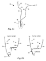
- Figure 1 shows a vehicle door 10 with a metal structure assembly having an improved corrosion resistance, according to the present invention.
- the metal structure assembly has at least a first and a second metal member, the first metal member is a vehicle door inner frame structure, such as an inner panel, while the second metal member is an aluminium outer panel attached thereto.
- the vehicle door inner frame structure comprises a steel material with a ZnMg based coating to prevent corrosion of the steel material.
- the ZnMg based coating can for instance be a Zn 2 Mg coating on a Zn coating.
- a steel sheet is coated with a Zn layer by electro galvanizing (EG) thereafter coated by a Zn 2 Mg layer by means of the Physical Vapour Deposition process (PVD), a process which, per se, is widely used for different applications in the general industry.
- PVD Physical Vapour Deposition process
- a steel sheet will pass over a heated metal source. As the metal is heated, metal vapour will evaporate from the metal source and condensate on the passing steel sheet.
- a vacuum source can be used to increase the evaporation rate. A metal layer is thereby formed on the steel sheet.
- the steel sheet can be coated on either side by simply returning the steel sheet over the heated metal source.
- the heated metal source is heated magnesium.
- the steel sheet is subjected to annealing, a heat treatment which effectively will alloy Zn with Mg and provider a layer with Zn 2 Mg above the Zn layer.
- a steel sheet can be provided with a ZnMg coating by means of a hot dip with zinc, magnesium and aluminium alloying elements.
- the ZnMg based alloy coating can for instance be a zinc alloy containing 0.8 - 3.5 weight % aluminium and 0.8 - 10.0 weight % magnesium.
- FIG 1 shows a vehicle door 10 having a vehicle door inner frame structure 11 (not shown), an outer panel 12, an inner panel 13, and a movable glass window 14.
- the vehicle door 10 is an automotive vehicle door and has an upper and lower edge 15, 16 the lower edge is intended to face towards the ground when the vehicle is in its ready to use position, while the upper edge is intended to be closer to the roof of the vehicle.
- the metal assembly according to the present invention, is very well suited for combining the inner and outer door structure, such as the one described below.
- FIG 2 which shows a close up of the lower edge 16 of the vehicle door 10, in this case a typical, hemmed door bottom design, where the vehicle inner door frame structure 11 of the vehicle door 10 comprises a first and a second surface 20, 21.
- the first surface 20 of the vehicle inner door frame structure 11 is attached to the inner surface 23, i.e. the surface which faces towards the inner of the vehicle door 10, of the outer panel 12.
- the inner surface 23 is also called the first surface 23 of the outer panel 12.
- a second attachment area 31 is formed as the second surface 21 of the inner door frame structure 11 is attached to the inner surface 23.
- the vehicle inner door frame structure 11 corresponds to the first metal sheet and the outer panel 12 corresponds to the second metal sheet.
- Figure 2b shows a close up of an alternative lower edge 16, i.e. a door bottom design, of the vehicle door 10.
- the vehicle inner door frame structure 11 of the vehicle door 10 comprises a first and a second surface 20, 21.
- the first surface 20 of the vehicle door 10 is attached to the inner surface 23, i.e. the surface which faces towards the inner of the vehicle door 10, of the outer panel 12.
- the inner surface 23 is also called the first surface 23 of the outer panel 12.
- the vehicle door frame structure 11 corresponds to the first metal sheet and the outer panel 12 corresponds to the second metal sheet.
- a drainage opening 31 is arranged below the attachment area 30 to drain any liquid which could assemble inside the vehicle door 10.
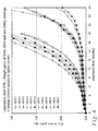
- figure 3 shows a diagram in which dry mass gain (measured in grams) caused by formation of insoluble corrosion products is plotted against time (weeks) for different samples of metal assemblies.
- the dry mass test method is outlined further below.
- Figure 3 shows a comparison of corrosion weight gains of cold-rolled steel, zinc-coated steel GI50, i.e. 50g/m 2 which is a standard Zn coating applied to a steel sheet with hot dip galvanization to a Zn layer thickness of about 7 ⁇ m on each side of the steel sheet, and ZM50, which is steel coated with a Zn layer alloyed with Mg, deposited as outlined above to a thickness of about 7 ⁇ m thickness.
- the GI50/GI50 sample is two steel sheets assembled together, each with a GI50 alloy.
- the coatings are compared also in electrical contact to an AA6016 aluminium sheet cover, all in the same standard crevice test configuration and under the test conditions described herein. (GI50/AI6 and ZM50/AI6 respectively).
- the Cold rolled steel (CRS/0) corroded through after 9 weeks (0,8 mm steel)
- the GI50 with glass cover GI50/0
- Samples with aluminium cover where ended fore analysis after 22 weeks. Only those with verified remaining electric contact between the sheets have been incorporated in the comparison.
- the ZMA50/AI6 sample which is a steel sheet with a ZM50 alloy coating assembled with an aluminium alloy sheet, shows a remarkably low dry mass gain, even after 24 weeks of testing.
- Aluminium sheet (AA6016) on GI50 coated steel corroded through 1 mm after 20-21 weeks, but steel plate base metal was almost uncorroded.
- Weight loss of aluminium sheet (AA6016) on ZnMg prototype coated steel after 22 weeks was only half that of Al cover on GI50 and with smoother attack.
- the ZnMg-coated steel base material was only slightly attacked.
- the weight gains in figure 3 are originating from corrosion of first zinc or zincmagnesium-coatings, then by rust formation. It is only when the metal assembly curves separates from the non metal assembly curve that the aluminium plate starts to corrode fully by galvanic interaction with the contiguous exposed steel. For the GI50 zinc-coated sample, this occurs at approximately 9 weeks, whereas for the zinc-magnesium coated steel it is only at about week 20 that the metal assembly curves separates from the non-metal assembly curves and aluminium starts to corrodes fully. This can seen as the ZM50/AI6 substantially follows the GI50/AI6 graph after 20 weeks.
- a 24 weeks test nominally corresponds to12 years in field service. It is believed that the aluminium/ZnMg-coated steel combination will pass without penetration and constitute a case where both aluminium and steel attack are moderated to acceptable levels. It should be noted that this experiment constitutes conditions where the exposed aluminium and attacked coated steel surfaces were of equal area. Considerable improvement in service life expectancy can be made by ensuring that the exposed bare aluminium surface in effective galvanic contact with the attacked ZnMg-coated steel can be made effectively larger than the area where the ZnMg coating has been consumed with left steel exposed. This is accomplished by not having the areas under corrosive load painted or just poorly protected by paint or any other coating.
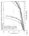
- figure 4 shows a comparison of corrosion weight gains of cold-rolled steel coated with traditional hot-dip zinc of two coatings weights (GI501-GI503 triplicate samples with 50 g/m2 and GI701-GI703 triplicate samples 70 g/m2), and two different ZnMg prototype coatings (ZM101-103 triplicate samples and ZM201-203 triplicate samples), all in the same standard crevice test configuration and under the test conditions described herein.
- the 0.8 mm thick GI50 coated panels perforated after 21 weeks.
- the dry mass gain is proportional to weight loss after removal of corrosion products.
- figure 5 shows a comparison of corrosion weight gains of cold-rolled steel coated with traditional hot-dip zinc of two coatings weights, 50 and 70 g/m2, and two different ZnMg prototype coatings, all in the same standard open test configuration and under the test conditions described herein. Note the general lower corrosion rates (different Y-axis scale) compared to figure 4 and that the ZnMg coatings are comparatively much more corrosion resistant than the traditional GI coatings in this open exposure mode.
- the Mg-containing passive layer that is present in the zinc-magnesium alloy has the ability to impede the primary, but weak galvanic effect from the aluminum alloy, which otherwise tends to somewhat enhance the dissolution of the zinc layer and shorten the incubation time before the galvanic attack of the aluminum alloy sets in from the underlying steel.
- the zinc-magnesium contacting layer eventually is consumed, there are less local attacks formed in the steel base compared with conventional zinc coatings.
- the absence of such active sites in the corroded zinc-magnesium coated steel is reducing the attack on the adjacent aluminum alloy, and no deep-seated local pits are formed, but instead there is an even, more shallow mode of attack on the aluminum side.
- Additional protection measures like wax can be omitted and it might even be sufficient to joint aluminium to zinc-magnesium coated steel without any further protection measures, provided the zinc-alloy coating is not too thin, preferably in the range of >7 ⁇ m, more preferably 7-12 ⁇ m.
- the first and/or the second metal member comprises at least a first and a second surface, wherein the first surface is free from coating in the vicinity of the first attachment area as well as in the attachment area.
- This is preferred for the first metal member.
- a free surface around, and at, the first attachment area provides a good surface area relationship without coating. For instance, if a local corrosion attack occurs a ZnMg surface, e.g. in a wet environment, and this surface is in contact with a aluminium metal member to provide a metal assembly, according to the present invention, the damage will not spread on the ZnMg coated surface, i.e.
- the aluminium member will provide for the damage in the steel with the main cathode protection, but spread over a relatively large surface area, so that its unavoidable attack is spread over a relatively large surface area, and thereby is acceptable.
- aluminium surfaces needs to be coated, e.g. by sealing wax (e.g. via electro dip sealing) or paint when in contact with steel.
- the outer panel 12 can be coated on its outer surface 24 while left uncoated on its inner surface 23. Furthermore it is realized that the inner surface 23 of the vehicle door 10 does not need additional seam sealing or anti corrosive treatment. Therefore, in an embodiment according to the present invention, the aluminium metal member has an anti corrosive treatment free surface at and around the first attachment area 30, and optionally an anti corrosive treated surface well separated from the first attachment area. An even more preferred embodiment according to the present invention, is that the first surface 20 of the inner vehicle door frame structure 11 is uncoated to provide a coating free surface. Thus an anti corrosive treatment free surface at and around the first attachment area 30, or the second attachment area 31 is very advantageous.
- the dry mass gain as shown in figures 3-5 have been measured using a standardized corrosion crevice test during which two metal sheets are held together.
- the atmospheric corrosion test i.e. the dry mass gain test, used to generate the result that forms the fundament for this application represents the worst vehicle conditions in terms of full access to the salt load and humidity. It serves as a general purpose atmospheric corrosion test and applies different materials, coatings, and interactions of materials, both as test specimens or in a designed component.
- the test is a standardized global corporate test procedure for laboratory corrosion testing. It is specially designed to correlate well to on-vehicle field performance for designs forming crevices, like weld joints and over-hemmings, which usually constitute the most engraving corrosive conditions on vehicles in field service. Two weeks of testing approximates one year in the most corrosive road environments, making the current test results to represent close to full vehicle service life conditions.
- the daily test procedure consists of a 6 h wet phase at room temp. with intermittent exposure to salt solution (0.5% NaCl) followed by a 2.5 h transition procedure with drying under climate control and a 15.5 h period with constant temperature and humidity (50°C, 70% RH). To this is added a 48 h weekend procedure under continued constant climate control. See figure 6 for a work day (Monday-Friday) test cycle.
- the reference coupons used in the referred test of this application has been described to depth in a recent publication (M.Strom, G. Strom and G. Strannhage, "New aspects on the atmospheric corrosion of bare and zinc coated steels in accelerated testing", Eurocorr07, Maastricht 2007.)
- the test design has been adopted of e.g. the French Corrosion Institute, where the design is currently used in a large project with the intention to objectively evaluate the quality of all major corrosion tests used in the automotive industry.
- Alloy coated steel e.g. Zinc (alloy)-coated or uncoated metal sheets from coil (gauge typically 0.7-1.0 mm), were laser-cut to flat test coupons, also referred to as sheets, 76 x 100 mm 2 .
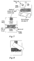
- a high-temperature resistant polyester tape (Shercon PC21) was used to mask a rectangular portion 66 x 20 mm 2 centered on the specimen surface with its upper edge 50 mm below the panel top according to figure 7
- the specimens have been phosphated and electro-coated on fixation racks in the Volvo Cars Torslanda paint shop (Chemetall, Gardobond 2600 + Gardolene 6800 - 6, BASF Cathoguard 350 FT25 - 7490).
- the tape After curing, the tape is removed and usually moved to protect the fixation position instead. For open exposure the panel is now ready for use.
- a PTFE sheet of 0.25 mm thickness is applied on the electro-coated portion on one of the sides of the previously masked area.
- the comparative test material e.g. an aluminium alloy metal member 76 x 26 mm 2 , are then centered and stacked over the exposed metallic surface and fixed in this position with two plastic clips found suitable for this purpose. In this way we have created a reproducible wedged confinement, 0.25 mm + the electro-coat thickness (ca 20 ⁇ m) on one side and the electro-coat thickness only on the other side.
- Figure 8 shows an example of crevice sample with electrically connected metallic cover. Here shown partly removed after exposure (cover in stainless steel on base plate in cold rolled-steel). Electrical stainless screw connection insulated from environment by butylic rubber on all sides. This is the configuration for mix-metal galvanic evaluation addressed in this application.
Landscapes
- Chemical & Material Sciences (AREA)
- Engineering & Computer Science (AREA)
- Mechanical Engineering (AREA)
- Chemical Kinetics & Catalysis (AREA)
- Materials Engineering (AREA)
- Metallurgy (AREA)
- Organic Chemistry (AREA)
- Prevention Of Electric Corrosion (AREA)
- Coating With Molten Metal (AREA)
Abstract
Description
- The present invention relates to a vehicle with a corrosion resistant metal assembly. The metal assembly has been found to be particularly useful in vehicle door structures.
- Generally, problems of corrosion on automotive vehicles have been improved over the years with the usage of galvanized steel. Galvanized steel is a common procedure at which a sheet of steel is coated by hot dip galvanizing, in which the sheet is moved through a bath of molten zinc. The molten zinc adheres to the steel, and as the sheet leaves the bath, the surplus of the zinc can be removed by the aid of gas knifes. The publication of
WO 2006002843 discloses the use of a steel sheet provided with a hot dip galvanized zinc alloy coating layer. The zinc alloy consists of: 0.3 - 2.3 weight % magnesium; 0.6 - 2.3 weight % aluminium; optional < 0.2 weight % of one or more additional elements; unavoidable impurities; the remainder being zinc. The zinc alloy coating can typically have a layer of a thickness of 5 - 12 µm. The zinc alloy coated steel sheet is said to have a good corrosion resistance and to be cheap to produce. The steel sheet described is further said to be used an as automotive part. The document is silent about any specific use however. - Furthermore, reduced weight in automotive vehicles is a main concern in order to reduce fuel consumption and CO2 emissions. Reduced weight calls for lighter materials, where aluminum is one candidate. However, structures in vehicles are often exposed to high load or stress. In this sense, aluminium is generally considered as a poor substitute for a steel structure. Combinations of aluminium and stronger materials, such as steel, are more likely to be successful in this sense. However, attachment areas between these materials are very often exposed to corrosive road environment, as a consequence, these mixed metal assemblies has been avoided due to severe galvanic corrosion, partly due to the unnoble properties of aluminium. Although some precautionary attempts have been made to seal off such attachment areas from exposure, e.g. by using different sealing methods or waxes, these methods have been shown to be either insufficient or very expensive.
- An example of such a solution is disclosed in the Japanese patent with the publication number
JP 2001335973 - It is an object of the present invention to provide a vehicle with an improved corrosion resistance metal structure assembly with a synergistic effect that which effectively slow down the build up of corrosion of the metal structure assembly as well as prevent local corrosive attacks. The above mentioned draw backs are at least partly solved by a vehicle comprising a metal structure assembly with an improved corrosion resistance comprising a first and a second metal member. The first metal member comprises a steel sheet having a first surface coated with at least one alloy. The second metal member is an aluminium member having a first surface. The first surface of the first metal member is attached to the first surface of the second metal member at at least a first attachment area. The at least one alloy is a ZnXMgY based alloy, such as Zn2Mg material layer. Such a layer is preferably arranged on a Zn coating layer. The metal assembly has been shown to provide surprisingly good corrosion preventive properties.
- In an embodiment according to the present invention, the at least one ZnXMgY based alloy alloy comprises 0.8-10 weight % of Mg. These type of coatings on steel are advantageous due to their lower productions costs and good manufacturing methods. The at least one alloy preferably comprises 1-5 % weight of Mg.
- In an application according to the present invention, the first metal member is a formed vehicle sheet metal structural part and the second metal member is another vehicle component, which surface is contacting the first member. In a preferred application according to the present invention, the first metal member is a vehicle inner door frame structure and optionally the second metal member is a vehicle door outer panel. The concept of using the metal assembly in the vehicle doors have been found to be very advantageous due to the harsh environment vehicle doors are subjected to. Hence, pressed stamp sheet steel based metal structures are very suitable for the present metal assemblies. The first metal member may be pressed stamp sheet steel based metal structure.
- In an embodiment according to the present invention, the first and/or the second metal member comprises coating free surface at the first attachment area. The coating free surface may be a surface free of anti corrosive treatment or a surface free from paint coating. The coating free surface may have an area of at least twice the area of the attachment area. It may further surround the attachment area. As is understood, the spread over a relatively large surface area, so that its unavoidable attack is spread over a relatively large surface area, and thereby is acceptable
- The present invention will hereafter be described in greater detail and with reference to the accompanying figure, in which;
-
figure 1 shows a schematic illustration of a vehicle door in which the metal assembly according to the present invention is very useful; -
figure 2a-2b shows a different schematic view of sections of a vehicle door as shown infigure 1 ; -
figure 3 shows a diagram with corrosion test results; -
figure 4 shows a diagram with test conditions; -
figure 5 shows a diagram with corrosion test results; -
figure 6 shows a diagram with corrosion test results; -
figure 7 shows a test sample assembly and; -
figure 8 shows a test sample assembly. -
Figure 1 shows avehicle door 10 with a metal structure assembly having an improved corrosion resistance, according to the present invention. In this non-limiting embodiment according to the present invention, the metal structure assembly has at least a first and a second metal member, the first metal member is a vehicle door inner frame structure, such as an inner panel, while the second metal member is an aluminium outer panel attached thereto. The vehicle door inner frame structure comprises a steel material with a ZnMg based coating to prevent corrosion of the steel material. - The ZnMg based coating can for instance be a Zn2Mg coating on a Zn coating. As an illustrative example, a steel sheet is coated with a Zn layer by electro galvanizing (EG) thereafter coated by a Zn2Mg layer by means of the Physical Vapour Deposition process (PVD), a process which, per se, is widely used for different applications in the general industry. When using the PVD process, a steel sheet will pass over a heated metal source. As the metal is heated, metal vapour will evaporate from the metal source and condensate on the passing steel sheet. A vacuum source can be used to increase the evaporation rate. A metal layer is thereby formed on the steel sheet. As an option, the steel sheet can be coated on either side by simply returning the steel sheet over the heated metal source. In this case the heated metal source is heated magnesium. After forming a Mg layer on the Zn layer, the steel sheet is subjected to annealing, a heat treatment which effectively will alloy Zn with Mg and provider a layer with Zn2Mg above the Zn layer.
- Optionally, a steel sheet can be provided with a ZnMg coating by means of a hot dip with zinc, magnesium and aluminium alloying elements. The ZnMg based alloy coating can for instance be a zinc alloy containing 0.8 - 3.5 weight % aluminium and 0.8 - 10.0 weight % magnesium. These amounts of magnesium and aluminium provides in itself a coating with a high corrosion resistance, a good surface quality, a good formability, and good welding properties at limited extra costs as compared to conventional hot dipped galvanising.
- However, the inventors have now found a synergistic effect when attaching a steel sheet with a Zn and Mg based alloy coating with an aluminium alloy member, preferably selected from the AA4000-AA6000 series. As will be shown, a remarkable corrosion resistive metal structure assembly is achieved by this combination.
- A very useful implementation area for the present invention will hereafter be illustrated in
figure 1. Figure 1 shows avehicle door 10 having a vehicle door inner frame structure 11 (not shown), anouter panel 12, aninner panel 13, and amovable glass window 14. Thevehicle door 10 is an automotive vehicle door and has an upper andlower edge figure 2 which shows a close up of thelower edge 16 of thevehicle door 10, in this case a typical, hemmed door bottom design, where the vehicle innerdoor frame structure 11 of thevehicle door 10 comprises a first and asecond surface first attachment area 30, thefirst surface 20 of the vehicle innerdoor frame structure 11 is attached to theinner surface 23, i.e. the surface which faces towards the inner of thevehicle door 10, of theouter panel 12. Theinner surface 23 is also called thefirst surface 23 of theouter panel 12. As can be seen further, asecond attachment area 31 is formed as thesecond surface 21 of the innerdoor frame structure 11 is attached to theinner surface 23. For the purpose of the present invention, the vehicle innerdoor frame structure 11 corresponds to the first metal sheet and theouter panel 12 corresponds to the second metal sheet.
Figure 2b shows a close up of an alternativelower edge 16, i.e. a door bottom design, of thevehicle door 10. The vehicle innerdoor frame structure 11 of thevehicle door 10 comprises a first and asecond surface first attachment area 30, thefirst surface 20 of thevehicle door 10 is attached to theinner surface 23, i.e. the surface which faces towards the inner of thevehicle door 10, of theouter panel 12. Theinner surface 23 is also called thefirst surface 23 of theouter panel 12. For the purpose of the present invention, the vehicledoor frame structure 11 corresponds to the first metal sheet and theouter panel 12 corresponds to the second metal sheet. As can be seen adrainage opening 31 is arranged below theattachment area 30 to drain any liquid which could assemble inside thevehicle door 10. - It has been found that the present invention is particularly useful in this technological field since vehicle doors, like the one just described, are very perceptive to corrosion due to their exposed environment.
- The surprisingly improved corrosion resistance is clearly shown in
figure 3 , which shows a diagram in which dry mass gain (measured in grams) caused by formation of insoluble corrosion products is plotted against time (weeks) for different samples of metal assemblies. The dry mass test method is outlined further below. -
Figure 3 shows a comparison of corrosion weight gains of cold-rolled steel, zinc-coated steel GI50, i.e. 50g/m2 which is a standard Zn coating applied to a steel sheet with hot dip galvanization to a Zn layer thickness of about 7 µm on each side of the steel sheet, and ZM50, which is steel coated with a Zn layer alloyed with Mg, deposited as outlined above to a thickness of about 7 µm thickness. The designations GI50/0 and ZM50/0 means that each coated steel is exposed under a glass sheet (0= glass sheet) forming a wedge crevice. The GI50/GI50 sample is two steel sheets assembled together, each with a GI50 alloy. The coatings are compared also in electrical contact to an AA6016 aluminium sheet cover, all in the same standard crevice test configuration and under the test conditions described herein. (GI50/AI6 and ZM50/AI6 respectively).
The Cold rolled steel (CRS/0) corroded through after 9 weeks (0,8 mm steel), the GI50 with glass cover (GI50/0) corroded through after 21 weeks (0,8 mm steel). Samples with aluminium cover where ended fore analysis after 22 weeks. Only those with verified remaining electric contact between the sheets have been incorporated in the comparison. As can readily be seen infigure 3 , the ZMA50/AI6 sample, which is a steel sheet with a ZM50 alloy coating assembled with an aluminium alloy sheet, shows a remarkably low dry mass gain, even after 24 weeks of testing.
Aluminium sheet (AA6016) on GI50 coated steel corroded through 1 mm after 20-21 weeks, but steel plate base metal was almost uncorroded.
Weight loss of aluminium sheet (AA6016) on ZnMg prototype coated steel after 22 weeks was only half that of Al cover on GI50 and with smoother attack. The ZnMg-coated steel base material was only slightly attacked. - The weight gains in
figure 3 , are originating from corrosion of first zinc or zincmagnesium-coatings, then by rust formation. It is only when the metal assembly curves separates from the non metal assembly curve that the aluminium plate starts to corrode fully by galvanic interaction with the contiguous exposed steel. For the GI50 zinc-coated sample, this occurs at approximately 9 weeks, whereas for the zinc-magnesium coated steel it is only at aboutweek 20 that the metal assembly curves separates from the non-metal assembly curves and aluminium starts to corrodes fully. This can seen as the ZM50/AI6 substantially follows the GI50/AI6 graph after 20 weeks. - A 24 weeks test nominally corresponds to12 years in field service.
It is believed that the aluminium/ZnMg-coated steel combination will pass without penetration and constitute a case where both aluminium and steel attack are moderated to acceptable levels. It should be noted that this experiment constitutes conditions where the exposed aluminium and attacked coated steel surfaces were of equal area. Considerable improvement in service life expectancy can be made by ensuring that the exposed bare aluminium surface in effective galvanic contact with the attacked ZnMg-coated steel can be made effectively larger than the area where the ZnMg coating has been consumed with left steel exposed. This is accomplished by not having the areas under corrosive load painted or just poorly protected by paint or any other coating. Under the assumption that wet crevices (hems, weld joints) are the service-life limiting corrosive condition, it can be utilized that in the adjacent open areas outside the crevice, the ZnMg will be intact for a considerably longer time than in the crevice, whereas the aluminium will be available to participate in the galvanic protection of the attacked, steel-exposing area in the crevice. Then the consumed aluminium will be distributed over a larger area and the risk of aluminium penetration will be further reduced. The general corrosion rate of freely exposed aluminium is quite low, so paint is not required for this reason, and the same applies for ZnMg in open exposure, provided not under considerable dirt load. - The above findings are supported in
figure 4 , which shows a comparison of corrosion weight gains of cold-rolled steel coated with traditional hot-dip zinc of two coatings weights (GI501-GI503 triplicate samples with 50 g/m2 and GI701-GI703 triplicate samples 70 g/m2), and two different ZnMg prototype coatings (ZM101-103 triplicate samples and ZM201-203 triplicate samples), all in the same standard crevice test configuration and under the test conditions described herein. The 0.8 mm thick GI50 coated panels perforated after 21 weeks. The dry mass gain is proportional to weight loss after removal of corrosion products. - Further,
figure 5 shows a comparison of corrosion weight gains of cold-rolled steel coated with traditional hot-dip zinc of two coatings weights, 50 and 70 g/m2, and two different ZnMg prototype coatings, all in the same standard open test configuration and under the test conditions described herein. Note the general lower corrosion rates (different Y-axis scale) compared tofigure 4 and that the ZnMg coatings are comparatively much more corrosion resistant than the traditional GI coatings in this open exposure mode. - Without being bound by theory, it is believed that the Mg-containing passive layer that is present in the zinc-magnesium alloy has the ability to impede the primary, but weak galvanic effect from the aluminum alloy, which otherwise tends to somewhat enhance the dissolution of the zinc layer and shorten the incubation time before the galvanic attack of the aluminum alloy sets in from the underlying steel. When the zinc-magnesium contacting layer eventually is consumed, there are less local attacks formed in the steel base compared with conventional zinc coatings. The absence of such active sites in the corroded zinc-magnesium coated steel is reducing the attack on the adjacent aluminum alloy, and no deep-seated local pits are formed, but instead there is an even, more shallow mode of attack on the aluminum side. This moderated aluminum corrosion in turn is sufficient to prevent the steel side from further attack. Hence, a synergetic effect seems to be present, where the overall system corrosion rate is considerably reduced and local attacks in the form of deep-seated local pits are effectively prevented. In a vehicle service-life perspective this means a substantially enhanced time to penetration of any of the sheet constituents. Our test results suggest that systems with this material combination can be used in corrosive environments without extraordinary protection measures. It even suggests that conventional add-on sealing or wax-protection become obsolete even in a 12-year perforation warranty perspective. The protection concept is ready for use in any combination of coated steel to aluminum. The increased corrosion protection of the coating itself (by its ability of forming a stable passivating barrier coating) also has a good chemical and electro-chemical compatibility with aluminum. Hence, the corrosion of the zinc-alloy coating will not be increased by the impact of the contacting aluminum, which sometimes is the case for pure zinc coatings. This will enable the barrier properties of the zinc-magnesium alloy coating to stay intact and the dissolution of the coating in contact crevices will be very slow, postponing the exposure of the underlying steel considerably and, hence, avoiding the galvanic interaction between steel and aluminum for a very long time. These results indicate that regular sealing measures, used for conventional contacts between zinc-coated steels are sufficient also in mix aluminum/steel combinations. Additional protection measures like wax can be omitted and it might even be sufficient to joint aluminium to zinc-magnesium coated steel without any further protection measures, provided the zinc-alloy coating is not too thin, preferably in the range of >7 µm, more preferably 7-12 µm.
- In an embodiment according to the present invention, the first and/or the second metal member comprises at least a first and a second surface, wherein the first surface is free from coating in the vicinity of the first attachment area as well as in the attachment area. This is preferred for the first metal member. As the inventors have found, a free surface around, and at, the first attachment area provides a good surface area relationship without coating. For instance, if a local corrosion attack occurs a ZnMg surface, e.g. in a wet environment, and this surface is in contact with a aluminium metal member to provide a metal assembly, according to the present invention, the damage will not spread on the ZnMg coated surface, i.e. exposed steel, since the corrosion attack will remain local and will even be retained due to a lighter accessible galvanic protection from the ZnMg surface. In this case, the aluminium member will provide for the damage in the steel with the main cathode protection, but spread over a relatively large surface area, so that its unavoidable attack is spread over a relatively large surface area, and thereby is acceptable. This is really contradictive with respect to the prior art, as it has been believed that aluminium surfaces needs to be coated, e.g. by sealing wax (e.g. via electro dip sealing) or paint when in contact with steel.
- Following the preferred example given above with the vehicle door and with reference to
figure 2 , theouter panel 12 can be coated on itsouter surface 24 while left uncoated on itsinner surface 23. Furthermore it is realized that theinner surface 23 of thevehicle door 10 does not need additional seam sealing or anti corrosive treatment. Therefore, in an embodiment according to the present invention, the aluminium metal member has an anti corrosive treatment free surface at and around thefirst attachment area 30, and optionally an anti corrosive treated surface well separated from the first attachment area. An even more preferred embodiment according to the present invention, is that thefirst surface 20 of the inner vehicledoor frame structure 11 is uncoated to provide a coating free surface. Thus an anti corrosive treatment free surface at and around thefirst attachment area 30, or thesecond attachment area 31 is very advantageous. - The dry mass gain, as shown in
figures 3-5 have been measured using a standardized corrosion crevice test during which two metal sheets are held together. The atmospheric corrosion test, i.e. the dry mass gain test, used to generate the result that forms the fundament for this application represents the worst vehicle conditions in terms of full access to the salt load and humidity. It serves as a general purpose atmospheric corrosion test and applies different materials, coatings, and interactions of materials, both as test specimens or in a designed component. The test is a standardized global corporate test procedure for laboratory corrosion testing. It is specially designed to correlate well to on-vehicle field performance for designs forming crevices, like weld joints and over-hemmings, which usually constitute the most engraving corrosive conditions on vehicles in field service. Two weeks of testing approximates one year in the most corrosive road environments, making the current test results to represent close to full vehicle service life conditions. - The daily test procedure consists of a 6 h wet phase at room temp. with intermittent exposure to salt solution (0.5% NaCl) followed by a 2.5 h transition procedure with drying under climate control and a 15.5 h period with constant temperature and humidity (50°C, 70% RH). To this is added a 48 h weekend procedure under continued constant climate control. See
figure 6 for a work day (Monday-Friday) test cycle. The reference coupons used in the referred test of this application has been described to depth in a recent publication (M.Strom, G. Strom and G. Strannhage, "New aspects on the atmospheric corrosion of bare and zinc coated steels in accelerated testing", Eurocorr07, Maastricht 2007.) The test design has been adopted of e.g. the French Corrosion Institute, where the design is currently used in a large project with the intention to objectively evaluate the quality of all major corrosion tests used in the automotive industry. - Alloy coated steel, e.g. Zinc (alloy)-coated or uncoated metal sheets from coil (gauge typically 0.7-1.0 mm), were laser-cut to flat test coupons, also referred to as sheets, 76 x 100 mm2. A high-temperature resistant polyester tape (Shercon PC21) was used to mask a rectangular portion 66 x 20 mm2 centered on the specimen surface with its
upper edge 50 mm below the panel top according tofigure 7 The specimens have been phosphated and electro-coated on fixation racks in the Volvo Cars Torslanda paint shop (Chemetall, Gardobond 2600 + Gardolene 6800 - 6, BASF Cathoguard 350 FT25 - 7490). After curing, the tape is removed and usually moved to protect the fixation position instead. For open exposure the panel is now ready for use. For testing in crevice condition a PTFE sheet of 0.25 mm thickness is applied on the electro-coated portion on one of the sides of the previously masked area. The comparative test material, e.g. an aluminium alloy metal member 76 x 26 mm2, are then centered and stacked over the exposed metallic surface and fixed in this position with two plastic clips found suitable for this purpose. In this way we have created a reproducible wedged confinement, 0.25 mm + the electro-coat thickness (ca 20 µm) on one side and the electro-coat thickness only on the other side. - In the corrosion tests the panels have been exposed at an inclination of 15 (+ 5°) to the normal (horizon) in plastic racks. The panel area above the exposed metallic portion will then act as a constant-area collector to salt-containing downfall. Note that the metallic surface is not exposed at the crevice mouth, but 3 mm inwards. This is a "digital" compromise to the gradual electro-coat thinning in real overlap flanges. For the remaining samples the glass slide was simply changed for an aluminum member.
-
Figure 8 shows an example of crevice sample with electrically connected metallic cover. Here shown partly removed after exposure (cover in stainless steel on base plate in cold rolled-steel). Electrical stainless screw connection insulated from environment by butylic rubber on all sides. This is the configuration for mix-metal galvanic evaluation addressed in this application.
Claims (15)
- A vehicle comprising a metal structure assembly with an improved corrosion resistance comprising a first and a second metal member (11, 12),
said first metal member (11) comprises a steel sheet having a first surface (20), said first surface (20) is coated with at least one alloy,
characterized in
that said second metal member (12) is an aluminium alloy member having a first surface (23) and in that said first surface (20) of said first metal member (11) is attached to said first surface (23) of said second metal member (12) at at least a first attachment area (30), and in that said at least one alloy is a ZnXMgY based alloy. - The vehicle according to claim 1, characterized in that said at least one alloy comprises a Zn2Mg material layer.
- The vehicle according to claim 2, characterized in that said Zn2Mg material layer is arranged on a Zn layer.
- The vehicle according to claim 1, characterized in that said at least one alloy comprises 0.8-10 weight % of Mg.
- The vehicle according to claim 4, characterized in that said at least one alloy comprises 1-5 % weight of Mg.
- The vehicle according to any of the preceding claims, characterized in that said second member comprises coating free surface at said first attachment area at which the aluminium alloy is substantially free to corrode.
- The vehicle according to claim 6, characterized in that said coating free surface has an area of at least twice the area as said attachment area.
- The vehicle according to claim 7, characterized in that said coating free surface area surrounds said attachment area.
- The vehicle according to any of the preceding claims, characterized in that said first metal member (11) and second metal member (12) forms part of a door of said vehicle.
- The vehicle according to claim 9, characterized in that said first metal member (11) is a vehicle inner door frame structure (11).
- The vehicle according claim 9 or 10, characterized in that said second metal member (12) is a vehicle door outer panel (12).
- The vehicle according to any of the preceding claims, characterized in that said first metal member is pressed stamp sheet steel based metal structure.
- The vehicle according to any of the preceding claims, characterized in that said first member comprises a coating free surface at said first attachment area.
- The vehicle according to claim 13, characterized in that said first metal member comprises a coating free surface at said first attachment and substantially around said first attachment area.
- The vehicle according to claim 14, characterized in that said coating free surface has an area of at least twice the area as said attachment area.
Priority Applications (2)
| Application Number | Priority Date | Filing Date | Title |
|---|---|---|---|
| EP08159783.3A EP2141255B1 (en) | 2008-07-04 | 2008-07-04 | Improved corrosion inhibiting structure |
| CN2009101502199A CN101619643B (en) | 2008-07-04 | 2009-06-19 | Improved corrosion inhibiting structure |
Applications Claiming Priority (1)
| Application Number | Priority Date | Filing Date | Title |
|---|---|---|---|
| EP08159783.3A EP2141255B1 (en) | 2008-07-04 | 2008-07-04 | Improved corrosion inhibiting structure |
Publications (2)
| Publication Number | Publication Date |
|---|---|
| EP2141255A1 true EP2141255A1 (en) | 2010-01-06 |
| EP2141255B1 EP2141255B1 (en) | 2020-03-18 |
Family
ID=39929799
Family Applications (1)
| Application Number | Title | Priority Date | Filing Date |
|---|---|---|---|
| EP08159783.3A Revoked EP2141255B1 (en) | 2008-07-04 | 2008-07-04 | Improved corrosion inhibiting structure |
Country Status (2)
| Country | Link |
|---|---|
| EP (1) | EP2141255B1 (en) |
| CN (1) | CN101619643B (en) |
Cited By (3)
| Publication number | Priority date | Publication date | Assignee | Title |
|---|---|---|---|---|
| WO2014184599A1 (en) | 2013-05-13 | 2014-11-20 | Arcelormittal Investigación Y Desarrollo Sl | Assembly of an aluminum component and of a steel component having a znalmg alloy coating |
| US20160031298A1 (en) * | 2013-04-05 | 2016-02-04 | Shiroki Corporation | Vehicle door sash having vertical pillar sash |
| CN105682960A (en) * | 2013-10-25 | 2016-06-15 | 麦格纳国际公司 | Two-part component |
Families Citing this family (7)
| Publication number | Priority date | Publication date | Assignee | Title |
|---|---|---|---|---|
| US8632118B2 (en) * | 2011-08-29 | 2014-01-21 | GM Global Technology Operations LLC | Body panel assembly and a method for manufacturing a body panel assembly |
| CN103306589A (en) * | 2013-07-16 | 2013-09-18 | 干年妃 | Car door inner board |
| KR101585477B1 (en) * | 2014-09-26 | 2016-01-15 | 현대자동차주식회사 | Door frame for vehicle with high anticorrosion and the method of manufacturing the same |
| JP2019510686A (en) * | 2016-04-04 | 2019-04-18 | クーパー−スタンダード・オートモーティブ・インコーポレーテッド | Weatherstrip assembly and method of separating dissimilar metals in a weatherstrip assembly |
| US20210130963A1 (en) * | 2019-11-06 | 2021-05-06 | GM Global Technology Operations LLC | Coated carbon fiber reinforced polymeric composites for corrosion protection |
| DE102020200326A1 (en) * | 2020-01-13 | 2021-07-15 | Thyssenkrupp Steel Europe Ag | Process for the production of a surface-refined and surface-conditioned steel sheet |
| JP2022145485A (en) * | 2021-03-18 | 2022-10-04 | 株式会社神戸製鋼所 | Vehicular side door |
Citations (7)
| Publication number | Priority date | Publication date | Assignee | Title |
|---|---|---|---|---|
| EP1146145A1 (en) * | 1999-09-17 | 2001-10-17 | Kawasaki Steel Corporation | Surface treated steel sheet and method for production thereof |
| JP2001335973A (en) | 2000-05-26 | 2001-12-07 | Nippon Light Metal Co Ltd | Corrosion protection method of base post type aluminum facility |
| US20030067187A1 (en) * | 2001-10-10 | 2003-04-10 | Ford Global Technologies, Inc. | Hem flange |
| JP2003341547A (en) * | 2002-05-27 | 2003-12-03 | Fuji Heavy Ind Ltd | Vehicle roof panel mounting structure |
| WO2006002843A1 (en) | 2004-06-29 | 2006-01-12 | Corus Staal Bv | Steel sheet with hot dip galvanized zinc alloy coating and process to produce it |
| EP1806200A1 (en) | 2004-10-26 | 2007-07-11 | HONDA MOTOR CO., Ltd. | Method for bonding iron-based member with aluminum-based member |
| EP1930194A1 (en) * | 2006-12-07 | 2008-06-11 | Ford Global Technologies, LLC | Vehicle door |
Family Cites Families (6)
| Publication number | Priority date | Publication date | Assignee | Title |
|---|---|---|---|---|
| JP3501256B2 (en) * | 1996-07-30 | 2004-03-02 | 日野自動車株式会社 | Car door |
| US6235410B1 (en) * | 1996-12-13 | 2001-05-22 | Nisshin Steel Co., Ltd. | Hot-dip Zn-Al-Mg coated steel sheet excellent in corrosion resistance and surface appearance and process for the production thereof |
| JP2002371345A (en) | 2001-06-13 | 2002-12-26 | Sumitomo Metal Ind Ltd | Manufacturing method of hot-dip Zn-Al-Mg alloy plated steel sheet |
| EP1693477A1 (en) * | 2005-02-22 | 2006-08-23 | ThyssenKrupp Steel AG | Coated steel plate |
| CN100415504C (en) * | 2005-06-28 | 2008-09-03 | 太原理工大学 | Corrosion-resistant magnesium-aluminum composite material and preparation method thereof |
| JP2008105087A (en) | 2006-10-27 | 2008-05-08 | Honda Motor Co Ltd | Method of joining iron member and aluminum member and iron-aluminum joined body |
-
2008
- 2008-07-04 EP EP08159783.3A patent/EP2141255B1/en not_active Revoked
-
2009
- 2009-06-19 CN CN2009101502199A patent/CN101619643B/en active Active
Patent Citations (7)
| Publication number | Priority date | Publication date | Assignee | Title |
|---|---|---|---|---|
| EP1146145A1 (en) * | 1999-09-17 | 2001-10-17 | Kawasaki Steel Corporation | Surface treated steel sheet and method for production thereof |
| JP2001335973A (en) | 2000-05-26 | 2001-12-07 | Nippon Light Metal Co Ltd | Corrosion protection method of base post type aluminum facility |
| US20030067187A1 (en) * | 2001-10-10 | 2003-04-10 | Ford Global Technologies, Inc. | Hem flange |
| JP2003341547A (en) * | 2002-05-27 | 2003-12-03 | Fuji Heavy Ind Ltd | Vehicle roof panel mounting structure |
| WO2006002843A1 (en) | 2004-06-29 | 2006-01-12 | Corus Staal Bv | Steel sheet with hot dip galvanized zinc alloy coating and process to produce it |
| EP1806200A1 (en) | 2004-10-26 | 2007-07-11 | HONDA MOTOR CO., Ltd. | Method for bonding iron-based member with aluminum-based member |
| EP1930194A1 (en) * | 2006-12-07 | 2008-06-11 | Ford Global Technologies, LLC | Vehicle door |
Non-Patent Citations (3)
| Title |
|---|
| HOSKING N.C, STRÖM M.A. ET AL: "CORROSION RESISTANCE OF ZINC-MAGNESIUM COATED STEEL", CORROSION SCIENCE, vol. 49, 2007, XP002505324 * |
| M.STROM; G. STROM; G. STRANNHAGE: "New aspects on the atmospheric corrosion of bare and zinc coated steels in accelerated testing", EUROCORR07, MAASTRICHT, 2007 |
| SONG G. JOHANNESSON B. ET AL: "GALVANIC CORROSION OF MAGNESIUM ALLOY AZ91D IN CONTACT WITH AN ALUMINIUM ALLOY, STEEL AND ZINC", CORROSION SCIENCE, vol. 46, 2004, XP002505325 * |
Cited By (9)
| Publication number | Priority date | Publication date | Assignee | Title |
|---|---|---|---|---|
| US20160031298A1 (en) * | 2013-04-05 | 2016-02-04 | Shiroki Corporation | Vehicle door sash having vertical pillar sash |
| WO2014184599A1 (en) | 2013-05-13 | 2014-11-20 | Arcelormittal Investigación Y Desarrollo Sl | Assembly of an aluminum component and of a steel component having a znalmg alloy coating |
| CN104487605A (en) * | 2013-05-13 | 2015-04-01 | 安赛乐米塔尔研究与发展有限责任公司 | Assembly of an aluminum component and of a steel component having a ZnAlMg alloy coating |
| RU2583424C1 (en) * | 2013-05-13 | 2016-05-10 | Арселормиттал | ASSEMBLY OF ALUMINIUM PARTS AND STEEL PARTS WITH COATING FROM ZnAlMg ALLOY |
| CN104487605B (en) * | 2013-05-13 | 2017-07-18 | 安赛乐米塔尔公司 | The component of aluminium element and steel element with ZnAlMg alloy coats |
| US11370279B2 (en) | 2013-05-13 | 2022-06-28 | Arcelormittal | Assembly of an aluminum component and of a steel component having a ZnAlMg alloy coating |
| CN105682960A (en) * | 2013-10-25 | 2016-06-15 | 麦格纳国际公司 | Two-part component |
| CN105682960B (en) * | 2013-10-25 | 2019-04-02 | 麦格纳国际公司 | two-piece construction |
| US10618384B2 (en) | 2013-10-25 | 2020-04-14 | Magna International Inc. | Two-part component |
Also Published As
| Publication number | Publication date |
|---|---|
| CN101619643B (en) | 2012-09-26 |
| EP2141255B1 (en) | 2020-03-18 |
| CN101619643A (en) | 2010-01-06 |
Similar Documents
| Publication | Publication Date | Title |
|---|---|---|
| EP2141255B1 (en) | Improved corrosion inhibiting structure | |
| Rai et al. | Effect of magnesium on corrosion behavior of hot-dip Zn-Al-Mg coating | |
| CN1829817B (en) | Method for producing a hardened steel part | |
| EP3266900B1 (en) | Molten al-zn-mg-si-plated steel sheet | |
| US4252866A (en) | Dual layer-coated electro-galvanized steel sheet for coating with excellent bare corrosion resistance, corrosion resistance after coating and formability | |
| JP5000039B2 (en) | Tin-plated or aluminum-plated surface-treated steel with excellent corrosion resistance | |
| KR20090007597A (en) | Flat steel products with anti-corrosion coating layer and manufacturing method thereof | |
| CN105051239B (en) | Hot-dip Al-Zn system's steel plates and its manufacturing method | |
| ES2982286T3 (en) | A process for manufacturing a galvanised steel sheet | |
| US10519559B2 (en) | Method for improving the weldability of high manganese content steel strips | |
| US12134816B2 (en) | Flat steel product having an improved zinc coating | |
| EP1146145A1 (en) | Surface treated steel sheet and method for production thereof | |
| Townsend | Continuous hot dip coatings | |
| KR101958129B1 (en) | Steel plate for fuel tank | |
| JPS5815554B2 (en) | Plated steel materials for cationic electrodeposition coating | |
| Manna et al. | Microstructure and electrochemical performance evaluation of Zn, Zn-5 wt.% Al and Zn-20 wt.% Al alloy coated steels | |
| EP4464813A1 (en) | Hot stamp molded article | |
| JP2001131762A (en) | Galvanized steel sheet for automobile body | |
| EP3508610B1 (en) | Hot-dip al-zn alloy coated steel sheet | |
| JP6480132B2 (en) | Al-plated steel sheet | |
| ES2902384T3 (en) | A method for manufacturing a coated steel sheet | |
| EP3030697B1 (en) | Structure for use in a corrosive environment | |
| JP6337711B2 (en) | Fused Al-based plated steel sheet | |
| TW202546252A (en) | Coated steel | |
| JP2016060946A (en) | MOLTEN Al-BASED PLATED SHEET STEEL |
Legal Events
| Date | Code | Title | Description |
|---|---|---|---|
| PUAI | Public reference made under article 153(3) epc to a published international application that has entered the european phase |
Free format text: ORIGINAL CODE: 0009012 |
|
| AK | Designated contracting states |
Kind code of ref document: A1 Designated state(s): AT BE BG CH CY CZ DE DK EE ES FI FR GB GR HR HU IE IS IT LI LT LU LV MC MT NL NO PL PT RO SE SI SK TR |
|
| AX | Request for extension of the european patent |
Extension state: AL BA MK RS |
|
| 17P | Request for examination filed |
Effective date: 20100126 |
|
| 17Q | First examination report despatched |
Effective date: 20100330 |
|
| AKX | Designation fees paid |
Designated state(s): DE GB SE |
|
| RAP1 | Party data changed (applicant data changed or rights of an application transferred) |
Owner name: VOLVO CAR CORPORATION |
|
| TPAC | Observations filed by third parties |
Free format text: ORIGINAL CODE: EPIDOSNTIPA |
|
| STAA | Information on the status of an ep patent application or granted ep patent |
Free format text: STATUS: EXAMINATION IS IN PROGRESS |
|
| GRAP | Despatch of communication of intention to grant a patent |
Free format text: ORIGINAL CODE: EPIDOSNIGR1 |
|
| STAA | Information on the status of an ep patent application or granted ep patent |
Free format text: STATUS: GRANT OF PATENT IS INTENDED |
|
| RIC1 | Information provided on ipc code assigned before grant |
Ipc: B60J 5/00 20060101ALI20190919BHEP Ipc: C23C 2/06 20060101AFI20190919BHEP Ipc: B23K 11/20 20060101ALI20190919BHEP Ipc: B60J 5/04 20060101ALI20190919BHEP |
|
| INTG | Intention to grant announced |
Effective date: 20191015 |
|
| GRAS | Grant fee paid |
Free format text: ORIGINAL CODE: EPIDOSNIGR3 |
|
| GRAA | (expected) grant |
Free format text: ORIGINAL CODE: 0009210 |
|
| STAA | Information on the status of an ep patent application or granted ep patent |
Free format text: STATUS: THE PATENT HAS BEEN GRANTED |
|
| AK | Designated contracting states |
Kind code of ref document: B1 Designated state(s): DE GB SE |
|
| REG | Reference to a national code |
Ref country code: GB Ref legal event code: FG4D |
|
| REG | Reference to a national code |
Ref country code: DE Ref legal event code: R096 Ref document number: 602008062316 Country of ref document: DE |
|
| PG25 | Lapsed in a contracting state [announced via postgrant information from national office to epo] |
Ref country code: SE Free format text: LAPSE BECAUSE OF FAILURE TO SUBMIT A TRANSLATION OF THE DESCRIPTION OR TO PAY THE FEE WITHIN THE PRESCRIBED TIME-LIMIT Effective date: 20200318 |
|
| REG | Reference to a national code |
Ref country code: DE Ref legal event code: R026 Ref document number: 602008062316 Country of ref document: DE |
|
| PLBI | Opposition filed |
Free format text: ORIGINAL CODE: 0009260 |
|
| PLAX | Notice of opposition and request to file observation + time limit sent |
Free format text: ORIGINAL CODE: EPIDOSNOBS2 |
|
| 26 | Opposition filed |
Opponent name: ARCELORMITTAL Effective date: 20201215 |
|
| PLAF | Information modified related to communication of a notice of opposition and request to file observations + time limit |
Free format text: ORIGINAL CODE: EPIDOSCOBS2 |
|
| GBPC | Gb: european patent ceased through non-payment of renewal fee |
Effective date: 20200704 |
|
| PG25 | Lapsed in a contracting state [announced via postgrant information from national office to epo] |
Ref country code: GB Free format text: LAPSE BECAUSE OF NON-PAYMENT OF DUE FEES Effective date: 20200704 |
|
| PLBB | Reply of patent proprietor to notice(s) of opposition received |
Free format text: ORIGINAL CODE: EPIDOSNOBS3 |
|
| RDAF | Communication despatched that patent is revoked |
Free format text: ORIGINAL CODE: EPIDOSNREV1 |
|
| APAH | Appeal reference modified |
Free format text: ORIGINAL CODE: EPIDOSCREFNO |
|
| APBM | Appeal reference recorded |
Free format text: ORIGINAL CODE: EPIDOSNREFNO |
|
| APBP | Date of receipt of notice of appeal recorded |
Free format text: ORIGINAL CODE: EPIDOSNNOA2O |
|
| APBQ | Date of receipt of statement of grounds of appeal recorded |
Free format text: ORIGINAL CODE: EPIDOSNNOA3O |
|
| PGFP | Annual fee paid to national office [announced via postgrant information from national office to epo] |
Ref country code: DE Payment date: 20230620 Year of fee payment: 16 |
|
| P01 | Opt-out of the competence of the unified patent court (upc) registered |
Effective date: 20231212 |
|
| APAH | Appeal reference modified |
Free format text: ORIGINAL CODE: EPIDOSCREFNO |
|
| APBU | Appeal procedure closed |
Free format text: ORIGINAL CODE: EPIDOSNNOA9O |
|
| REG | Reference to a national code |
Ref country code: DE Ref legal event code: R103 Ref document number: 602008062316 Country of ref document: DE Ref country code: DE Ref legal event code: R064 Ref document number: 602008062316 Country of ref document: DE |
|
| RDAG | Patent revoked |
Free format text: ORIGINAL CODE: 0009271 |
|
| STAA | Information on the status of an ep patent application or granted ep patent |
Free format text: STATUS: PATENT REVOKED |
|
| 27W | Patent revoked |
Effective date: 20240715 |