EP2139771B1 - System for detecting the passage of objects with a rfid label and method using such system - Google Patents
System for detecting the passage of objects with a rfid label and method using such system Download PDFInfo
- Publication number
- EP2139771B1 EP2139771B1 EP07731417A EP07731417A EP2139771B1 EP 2139771 B1 EP2139771 B1 EP 2139771B1 EP 07731417 A EP07731417 A EP 07731417A EP 07731417 A EP07731417 A EP 07731417A EP 2139771 B1 EP2139771 B1 EP 2139771B1
- Authority
- EP
- European Patent Office
- Prior art keywords
- objects
- antenna
- passage
- reader
- mobile support
- Prior art date
- Legal status (The legal status is an assumption and is not a legal conclusion. Google has not performed a legal analysis and makes no representation as to the accuracy of the status listed.)
- Not-in-force
Links
Images


Classifications
-
- G—PHYSICS
- G06—COMPUTING OR CALCULATING; COUNTING
- G06K—GRAPHICAL DATA READING; PRESENTATION OF DATA; RECORD CARRIERS; HANDLING RECORD CARRIERS
- G06K7/00—Methods or arrangements for sensing record carriers, e.g. for reading patterns
- G06K7/10—Methods or arrangements for sensing record carriers, e.g. for reading patterns by electromagnetic radiation, e.g. optical sensing; by corpuscular radiation
- G06K7/10009—Methods or arrangements for sensing record carriers, e.g. for reading patterns by electromagnetic radiation, e.g. optical sensing; by corpuscular radiation sensing by radiation using wavelengths larger than 0.1 mm, e.g. radio-waves or microwaves
- G06K7/10316—Methods or arrangements for sensing record carriers, e.g. for reading patterns by electromagnetic radiation, e.g. optical sensing; by corpuscular radiation sensing by radiation using wavelengths larger than 0.1 mm, e.g. radio-waves or microwaves using at least one antenna particularly designed for interrogating the wireless record carriers
- G06K7/10346—Methods or arrangements for sensing record carriers, e.g. for reading patterns by electromagnetic radiation, e.g. optical sensing; by corpuscular radiation sensing by radiation using wavelengths larger than 0.1 mm, e.g. radio-waves or microwaves using at least one antenna particularly designed for interrogating the wireless record carriers the antenna being of the far field type, e.g. HF types or dipoles
-
- G—PHYSICS
- G06—COMPUTING OR CALCULATING; COUNTING
- G06K—GRAPHICAL DATA READING; PRESENTATION OF DATA; RECORD CARRIERS; HANDLING RECORD CARRIERS
- G06K7/00—Methods or arrangements for sensing record carriers, e.g. for reading patterns
- G06K7/10—Methods or arrangements for sensing record carriers, e.g. for reading patterns by electromagnetic radiation, e.g. optical sensing; by corpuscular radiation
- G06K7/10009—Methods or arrangements for sensing record carriers, e.g. for reading patterns by electromagnetic radiation, e.g. optical sensing; by corpuscular radiation sensing by radiation using wavelengths larger than 0.1 mm, e.g. radio-waves or microwaves
- G06K7/10316—Methods or arrangements for sensing record carriers, e.g. for reading patterns by electromagnetic radiation, e.g. optical sensing; by corpuscular radiation sensing by radiation using wavelengths larger than 0.1 mm, e.g. radio-waves or microwaves using at least one antenna particularly designed for interrogating the wireless record carriers
-
- G—PHYSICS
- G06—COMPUTING OR CALCULATING; COUNTING
- G06K—GRAPHICAL DATA READING; PRESENTATION OF DATA; RECORD CARRIERS; HANDLING RECORD CARRIERS
- G06K7/00—Methods or arrangements for sensing record carriers, e.g. for reading patterns
- G06K7/10—Methods or arrangements for sensing record carriers, e.g. for reading patterns by electromagnetic radiation, e.g. optical sensing; by corpuscular radiation
- G06K7/10009—Methods or arrangements for sensing record carriers, e.g. for reading patterns by electromagnetic radiation, e.g. optical sensing; by corpuscular radiation sensing by radiation using wavelengths larger than 0.1 mm, e.g. radio-waves or microwaves
- G06K7/10366—Methods or arrangements for sensing record carriers, e.g. for reading patterns by electromagnetic radiation, e.g. optical sensing; by corpuscular radiation sensing by radiation using wavelengths larger than 0.1 mm, e.g. radio-waves or microwaves the interrogation device being adapted for miscellaneous applications
- G06K7/10415—Methods or arrangements for sensing record carriers, e.g. for reading patterns by electromagnetic radiation, e.g. optical sensing; by corpuscular radiation sensing by radiation using wavelengths larger than 0.1 mm, e.g. radio-waves or microwaves the interrogation device being adapted for miscellaneous applications the interrogation device being fixed in its position, such as an access control device for reading wireless access cards, or a wireless ATM
- G06K7/10425—Methods or arrangements for sensing record carriers, e.g. for reading patterns by electromagnetic radiation, e.g. optical sensing; by corpuscular radiation sensing by radiation using wavelengths larger than 0.1 mm, e.g. radio-waves or microwaves the interrogation device being adapted for miscellaneous applications the interrogation device being fixed in its position, such as an access control device for reading wireless access cards, or a wireless ATM the interrogation device being arranged for interrogation of record carriers passing by the interrogation device
- G06K7/10435—Methods or arrangements for sensing record carriers, e.g. for reading patterns by electromagnetic radiation, e.g. optical sensing; by corpuscular radiation sensing by radiation using wavelengths larger than 0.1 mm, e.g. radio-waves or microwaves the interrogation device being adapted for miscellaneous applications the interrogation device being fixed in its position, such as an access control device for reading wireless access cards, or a wireless ATM the interrogation device being arranged for interrogation of record carriers passing by the interrogation device the interrogation device being positioned close to a conveyor belt or the like on which moving record carriers are passing
Definitions
- the present invention relates to a system for detecting the passage of objects, persons or animals carrying a radio frequency identification (RFID) tag.
- RFID radio frequency identification
- the invention also relates to the application of the system according to the invention to the identification of objects equipped with RFID tags transported on a conveyor.
- the aforementioned objects are luggage transported to a gantry or tunnel.
- gantries or tunnels are equipped with rigid and fixed antennas, connected to an RFID reader which allows remote reading labels fixed or glued on the luggage, thus allowing to identify them.
- the object that is to say the luggage, may escape reading and not be identified.
- the object of the present invention is to overcome the above disadvantages.
- RFID radio frequency identification tag
- the plane of the antenna carried by this support changes orientation with respect to that of the RFID tag carried by the objects.
- the mobile support is rigid and is articulated along an axis located above the passage zone.
- the mobile support pivots when it is encountered by an object.
- the mobile support is made of flexible material and is freely suspended at a point above the passage zone.
- the mobile support bends when it is encountered by an object, while remaining in contact with the object, until the latter, continuing its movement, completely escapes the mobile support. This gives excellent conditions for reading the label carried by the objects.
- the antenna is located near the lower end of the movable support to be in the passage zone.
- the antenna is located near the objects to be identified, which makes it possible to obtain optimal reading conditions.
- the support comprises a plurality of flexible strips arranged next to one another in a plane transverse to the direction of passage of said objects, persons or animals, each of said strips carrying, at its lower part, an RFID reading antenna.
- This arrangement makes it possible to avoid any risk that an object is not identified.
- the flexible strips extend over substantially the entire width of the passage, and the lower end of the flexible bands is located near the base of said passage.
- the antenna is located on the face of the strip opposite to that coming into contact with the objects. This avoids any risk of friction between the object and the antenna which could deteriorate it.
- the strips of the device according to the invention may be of any flexible material, such as synthetic material, rubber or textile.
- the antenna and the electrical conductor connected thereto may be constituted by a circuit board on the strip.
- Each of the mobile supports carrying an antenna the system comprising a reader for the information received by the antennas
- this system comprises a multiplexer providing a connection between the antennas and the reader.
- a central unit connected to the reader may further be provided for processing the information read by said reader.
- the system includes a processing unit comprising the multiplexer, the reader and the central unit. Said assembly can be assigned locally to the detection device. That is, each detection device is associated with a single processing set.
- the treatment assembly may be included in a housing mounted on, or in close proximity to, said sensing device.
- the system may further include remote central processing means adapted to handle other information than that from the processing set. So the system can understand several detection devices, as well as one or more sorting devices for objects, and the central processing means can be adapted to sort an object, in particular according to the information gathered during the passage of the objects through the detection device (s).
- the system may be a baggage sorting system at check-in or during transit through an airport. It can also be a postal sorting system.
- a method using a detection device is characterized in that each of the antennas is interrogated successively, preferably by means of a multiplexer providing a connection between the antennas and the reader. .
- the successive interrogation is advantageously conducted at a frequency, depending on the speed of advance of the object, person or animal crossing said barrier, so that any antenna that would detect the presence of the object, the person or the animal is interrogated at least once during the time during which this presence is detected by this antenna.
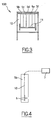
- the device 100 for detecting the passage of objects 1, 2 carrying a radio frequency identification (RFID) tag 3 comprises at least one mobile support 5, 5a which, at rest, forms a barrier by relative to the passage of said objects 1, 2, and which, in contact with them, is likely to move to an erased position (shown in broken lines at Figures 1 and 2 ).
- This mobile support 5, 5a carries an antenna 6 electrically connected to a reader 7 of RFID tags.
- the mobile support is rigid and is articulated along an axis 8 situated above the passage zone of the objects 1, 2.
- the movable support 5a is of flexible material, and is freely suspended at a point 9 situated above the passage zone of the objects 1, 2.
- the antenna 6 is located near the lower end of the movable support 5, 5a to be in the passage zone of the objects 1, 2.
- the support comprises a plurality of flexible strips 5b, 5c, 5d, 5e 5f, arranged next to each other, in a plane transverse to the direction of passage of the objects.
- Each of the bands 5b, 5c, 5d, 5e, 5f carries, at its lower part, an antenna 6 RFID reading.
- the flexible strips 5b, 5c, 5d, 5e, 5f extend over substantially the entire width of the passage of the objects, and the lower end of the flexible strips 5b, 5c, 5d, 5e, 5f is located near the base of said passage.
- the antenna 6 is located on the face of the strip 5b, 5c, 5d, 5e, 5f, opposite to that coming into contact with the objects, to prevent them from damaging this antenna 6.
- the strips 5b, 5c, 5d, 5e, 5f can be made of any synthetic or textile material, provided that it is flexible enough to be erased when passing objects.
- the antenna 6 and the electrical conductor 10 connected thereto may be constituted by an electrical circuit printed on the strip 5b, 5c, 5d, 5e, 5f.
- the figure 3 illustrates an application of the device the invention to the identification of objects equipped with RFID tags carried on a conveyor 11.
- the objects to be identified may be luggage transported in a tunnel 12 (see figure 3 ), such as those installed at airports.
- the device according to the invention makes it possible to tend towards the identification of 100% of the luggage transported on the conveyor.
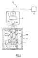
- a system 101 according to the invention will now be described, this system including a detection device 100.
- the device 100 is substantially of the same type as those already described with reference to the preceding figures. It will be noted however that the four bands 5b, 5e constituting the barrier are not contiguous, nor overlapping, but have between them free intervals. Nevertheless, these strips are sufficiently close together for an object passing through the device 100 to be effectively detected.
- the system 101 further comprises a processing unit 20, disposed locally relative to the detection device 100, and remote central processing means SC relative to the detection device.
- the processing unit comprises an MX multiplexer, a reader 7 and a CPU UC.
- Each of the four bands comprises, at its base, an antenna 6 connected by a respective conductor 10 to the multiplexer MX.
- the information received by the antennas and thus multiplexed, is then transmitted via a single conductor 110 to the reader 7, responsible for reading this information.
- the information is then transmitted to the central unit UC for local processing.
- the information may include the destination of a piece of luggage that has just been recorded. This information, once processed locally, can then be transmitted in whole or in part to the central processing means SC.
- the central processing means are provided for exploiting the system data at a central management system level.
- the central processing means may be provided to manage an apparatus for sorting baggage. They may be provided in particular for operating referral systems for baggage and / or for verifying that luggage initially registered by a passenger actually enter and exit the sorting equipment.
- a method using such a multiplexer system consists in successively interrogating each of the antennas of the detection device. This scanning is conducted at a frequency calculated as a function of the crossing speed of the device by the objects to be identified, so that any antenna which would detect an object is interrogated at least once during the time during which the presence of said object is detected. by this antenna.
- the central unit is advantageously configured to avoid double detection, for example if during two successive interrogations the same antenna detects the same object, or when two different antennas simultaneously or successively detect the same object.
- the reader 7 itself which can comprise an antenna reading algorithm detecting the signal of greater amplitude coming from the multiplexer, which thus designates the antenna best placed to read at a given instant the or labels located on the objects to be checked. The information from this antenna is then read completely and recorded by the reader to be transmitted to the central management system SC. Then, the reader reads the new signal of higher amplitude collected and reads the information of the new antenna thus selected.
- a device according to the invention is particularly advantageous with regard to the devices of the prior art.
- the reading rate of an RFID tag in the most unfavorable position is on average 71.3%, whereas in a device according to the invention, comprising antennas on flexible bands, the reading rate is 93.6%.
- the most unfavorable position is the case where the label is located under the object, in contact with the conveyor and close to the metal materials of the latter.
- the device according to the invention makes it possible to recognize 99.98% of the baggage passing in front of the antennas of the device according to the invention.
- the invention can also be applied to the identification of persons or animals crossing an access door or a gantry.
- a detection device may not include antenna on each of the mobile supports, but sufficiently for an effective detection of objects, people or animals that cross it.
- the detection device according to the invention may further comprise one or more antennas carried by fixed parts, which can also be multiplexed with the antennas carried by the mobile supports.
- the fixed antennas can be arranged below relative to the objects crossing the device, thus improving the detection of the RFID tags that would be positioned under the objects.
- the antennas can be placed at various places of mobile, rigid or flexible supports.
- the antennas 6 can be arranged vertically one underneath others towards the free end of the support 5 ', mobile about a vertical axis 8', as shown in FIG. figure 6 .
- antennas can also, and without departing from the scope of the invention, be arranged in an orderly or random manner on the entire surface of the movable support according to the place and objects to which the invention is applied.
- One of the important applications of the present invention is to make it possible to insert a curtain according to the invention in an existing sorting tunnel, without having to make substantial modifications to the conveyor system, in order to allow RFID control of the objects placed on the tunnel conveyor.
- the introduction of the current systems of RFID antennas placed along the walls of an existing sorting tunnel requires to replace all the metal parts of the tunnel and the conveyor to the right of the antenna area by plastic parts in order not to interfere with the reading of the antennas.
- movable supports for example flexible bands
Landscapes
- Engineering & Computer Science (AREA)
- Health & Medical Sciences (AREA)
- Toxicology (AREA)
- Physics & Mathematics (AREA)
- Computer Networks & Wireless Communication (AREA)
- Electromagnetism (AREA)
- General Health & Medical Sciences (AREA)
- Artificial Intelligence (AREA)
- Computer Vision & Pattern Recognition (AREA)
- General Physics & Mathematics (AREA)
- Theoretical Computer Science (AREA)
- Geophysics And Detection Of Objects (AREA)
Description
La présente invention concerne un système pour la détection du passage d'objets, de personnes ou d'animaux portant une étiquette d'identification par fréquence radio (RFID).The present invention relates to a system for detecting the passage of objects, persons or animals carrying a radio frequency identification (RFID) tag.
L'invention vise également l'application du systèm selon l'invention à l'identification d'objets équipés d'étiquettes RFID, transportés sur un convoyeur.The invention also relates to the application of the system according to the invention to the identification of objects equipped with RFID tags transported on a conveyor.
Dans une application préférée de l'invention, les objets précités sont des bagages transportés vers un portique ou tunnel.In a preferred application of the invention, the aforementioned objects are luggage transported to a gantry or tunnel.
Dans cette application, les portiques ou tunnels sont équipés d'antennes rigides et fixes, reliées à un lecteur RFID qui permet de lire à distance les étiquettes fixées ou collées sur les bagages, en permettant ainsi d'identifier ceux-ci.In this application, gantries or tunnels are equipped with rigid and fixed antennas, connected to an RFID reader which allows remote reading labels fixed or glued on the luggage, thus allowing to identify them.
Les documents
Cependant, les deux paramètres suivants agissent sur le lecteur des étiquettes.
- la distance entre les antennes et l'étiquette RFID
- l'orientation du plan de l'antenne par rapport au plan de l'étiquette
- the distance between the antennas and the RFID tag
- the orientation of the plane of the antenna in relation to the plane of the label
Si cette distance ou si cette orientation n'est pas optimale, l'objet, c'est-à-dire le bagage, risque d'échapper à la lecture et de ne pas être identifié.If this distance or if this orientation is not optimal, the object, that is to say the luggage, may escape reading and not be identified.
Par ailleurs, les perturbations mutuelles entre plusieurs dispositifs de lecture ou écriture RFID peuvent également affecter le bon fonctionnement du système.Moreover, the mutual disturbances between several RFID reading or writing devices can also affect the proper functioning of the system.
Le but de la présente invention est de remédier aux inconvénients ci-dessus.The object of the present invention is to overcome the above disadvantages.
Ce but est atteint, selon l'invention, grâce à un système pour la détection du passage d'objets, de personnes ou d'animaux portant une étiquette d'identification par fréquence radio (RFID) selon la revendication 1.This object is achieved, according to the invention, by means of a system for detecting the passage of objects, persons or animals carrying a radio frequency identification tag (RFID) according to
Ainsi, lorsque le support mobile est déplacé par les objets et autres, le pian de l'antenne portée par ce support change d'orientation par rapport à celui de l'étiquette RFID portée par les objets.Thus, when the mobile support is moved by objects and the like, the plane of the antenna carried by this support changes orientation with respect to that of the RFID tag carried by the objects.
Les conditions de lecture de cette étiquette sont ainsi nettement améliorées par rapport aux dispositifs connus utilisant des antennes fixes.The reading conditions of this label are thus significantly improved compared to known devices using fixed antennas.
Dans un exemple de réalisation de l'invention, le support mobile est rigide et est articulé suivant un axe situé au-dessus de la zone de passage.In an exemplary embodiment of the invention, the mobile support is rigid and is articulated along an axis located above the passage zone.
Ainsi, le support mobile pivote lorsqu'il est rencontré par un objet.Thus, the mobile support pivots when it is encountered by an object.
Dans une version préférée de l'invention, le support mobile est en matière souple et est suspendu librement en un point situé au-dessus de la zone de passage.In a preferred version of the invention, the mobile support is made of flexible material and is freely suspended at a point above the passage zone.
Ainsi, le support mobile se plie lorsqu'il est rencontré par un objet, tout en restant en contact avec l'objet, jusqu'à ce que celui-ci, en poursuivant son déplacement, échappe complètement au support mobile. On obtient ainsi d'excellentes conditions de lecture de l'étiquette portée par les objets.Thus, the mobile support bends when it is encountered by an object, while remaining in contact with the object, until the latter, continuing its movement, completely escapes the mobile support. This gives excellent conditions for reading the label carried by the objects.
De préférence, l'antenne est située près de l'extrémité inférieure du support mobile pour être dans la zone de passage.Preferably, the antenna is located near the lower end of the movable support to be in the passage zone.
Ainsi, l'antenne est située près des objets à identifier, ce qui permet d'obtenir des conditions de lecture optimales.Thus, the antenna is located near the objects to be identified, which makes it possible to obtain optimal reading conditions.
Dans une version avantageuse de l'invention, le support comprend plusieurs bandes souples, disposées les unes à côté des autres, dans un plan transversal à la direction de passage desdits objets, personnes ou animaux, chacune desdites bandes portant, à sa partie inférieure, une antenne de lecture RFID.In an advantageous version of the invention, the support comprises a plurality of flexible strips arranged next to one another in a plane transverse to the direction of passage of said objects, persons or animals, each of said strips carrying, at its lower part, an RFID reading antenna.
Grâce à ces bandes souples juxtaposées, oh peut effectuer une lecture de plusieurs objets passant simultanément au travers du rideau souple constitué par les bandes ou d'objets situés en un point quelconque de la largeur de passage.With these flexible strips juxtaposed, oh can perform a reading of several objects passing simultaneously through the flexible curtain formed by the strips or objects located at any point of the passage width.
Cette disposition permet d'éviter tout risque qu'un objet ne soit pas identifié.This arrangement makes it possible to avoid any risk that an object is not identified.
De préférence, les bandes souples s'étendent sur sensiblement toute la largeur du passage, et l'extrémité inférieure des bandes souples est située près de la base dudit passage.Preferably, the flexible strips extend over substantially the entire width of the passage, and the lower end of the flexible bands is located near the base of said passage.
Avantageusement, l'antenne est située sur la face de la bande opposée à celle venant en contact avec les objets. On évite ainsi tout risque de frottement entre l'objet et l'antenne qui pourrait détériorer celle-ci.Advantageously, the antenna is located on the face of the strip opposite to that coming into contact with the objects. This avoids any risk of friction between the object and the antenna which could deteriorate it.
Les bandes du dispositif selon l'invention peuvent être en toute matière souple, telle que matière synthétique, caoutchouc ou textile.The strips of the device according to the invention may be of any flexible material, such as synthetic material, rubber or textile.
L'antenne et le conducteur électrique relié à celle-ci, peuvent être constitués par un circuit imprimé sur la bande.The antenna and the electrical conductor connected thereto may be constituted by a circuit board on the strip.
Chacun des supports mobiles portant une antenne, le système comprenant un lecteur pour les informations reçues par les antennes, ce système comprend un multiplexeur assurant une liaison entre les antennes et le lecteur. Ainsi, lorsque plusieurs objets franchissent sensiblement simultanément la barrière, ils peuvent être détectés et identifiés par des antennes respectives, sans perte d'information, les informations relatives à chacun des objets respectifs étant toutes lues par le lecteur.Each of the mobile supports carrying an antenna, the system comprising a reader for the information received by the antennas, this system comprises a multiplexer providing a connection between the antennas and the reader. Thus, when several objects substantially cross the barrier simultaneously, they can be detected and identified by respective antennas without loss of information, the information relating to each of the respective objects being all read by the reader.
Une unité centrale reliée au lecteur peut en outre être prévue pour assurer le traitement des informations lues par ledit lecteur. Avantageusement, le système inclut un ensemble de traitement comprenant le multiplexeur, le lecteur et l'unité centrale. Ledit ensemble peut être affecté localement au dispositif de détection. C'est-à-dire que chaque dispositif de détection est associé à un unique ensemble de traitement. L'ensemble de traitement peut être inclus dans un boîtier monté sur ledit, ou a proximité immédiate dudit, dispositif de détection.A central unit connected to the reader may further be provided for processing the information read by said reader. Advantageously, the system includes a processing unit comprising the multiplexer, the reader and the central unit. Said assembly can be assigned locally to the detection device. That is, each detection device is associated with a single processing set. The treatment assembly may be included in a housing mounted on, or in close proximity to, said sensing device.
Le système peut en outre comprendre des moyens de traitement centraux distants, adaptés pour traiter d'autres informations que celles issues de l'ensemble de traitement. Ainsi, le système peut comprendre plusieurs dispositifs de détection, ainsi qu'un ou plusieurs dispositifs de triage pour des objets, et les moyens de traitement centraux peuvent être adaptés pour trier un objet, notamment en fonction des informations recueillies lors du passage de l'objets au travers du ou des dispositif(s) de détection.The system may further include remote central processing means adapted to handle other information than that from the processing set. So the system can understand several detection devices, as well as one or more sorting devices for objects, and the central processing means can be adapted to sort an object, in particular according to the information gathered during the passage of the objects through the detection device (s).
Le système peut être un système de tri de bagage à l'enregistrement ou lors d'un transit dans un aéroport. Il peut être aussi un système de tri postal.The system may be a baggage sorting system at check-in or during transit through an airport. It can also be a postal sorting system.
Selon l'invention, un procédé utilisant un dispositif de détection selon l'invention, est caractérisé en ce que l'on interroge successivement chacune des antennes, de préférence à l'aide d'un multiplexeur assurant une liaison entre les antennes et le lecteur. L'interrogation successive est avantageusement menée à une fréquence, fonction de la vitesse d'avancement de l'objet, personne ou animal franchissant ladite barrière, de sorte que toute antenne qui détecterait la présence de l'objet, la personne ou l'animal soit interrogée au moins une fois durant le temps pendant lequel cette présence est détectée par cette antenne.According to the invention, a method using a detection device according to the invention is characterized in that each of the antennas is interrogated successively, preferably by means of a multiplexer providing a connection between the antennas and the reader. . The successive interrogation is advantageously conducted at a frequency, depending on the speed of advance of the object, person or animal crossing said barrier, so that any antenna that would detect the presence of the object, the person or the animal is interrogated at least once during the time during which this presence is detected by this antenna.
D'autres caractéristiques et avantages de l'invention apparaîtront encore dans la description ci-après.Other features and advantages of the invention will become apparent in the description below.
Aux dessins annexés, donnés à titre d'exemples non limitatifs :
- la
figure 1 est une vue latérale schématique d'un premier exemple de dispositif de détection de passage d'objets, selon l'invention, - la
figure 2 est une vue analogue à lafigure 1 montrant un autre exemple du dispositif selon l'invention, - la
figure 3 est une vue en coupe transversale d'un tunnel de passage de bagages équipé d'un dispositif selon l'invention comportant plusieurs bandes souples, - la
figure 4 est une vue de l'une des bandes souples du dispositif de lafigure 3 . - la
figure 5 est une vue schématique d'un système selon l'invention utilisant un dispositif selon l'invention. - La
figure 6 est une vue schématique d'une variante d'un système selon l'invention dans laquelle les supports mobiles sont des rideaux souples obturant une porte et s'ouvrant par pivotement autour d'un axe vertical.
- the
figure 1 is a schematic side view of a first example of a device for detecting the passage of objects, according to the invention, - the
figure 2 is a view similar to thefigure 1 showing another example of the device according to the invention, - the
figure 3 is a cross-sectional view of a baggage tunnel equipped with a device according to the invention comprising a plurality of flexible strips, - the
figure 4 is a view of one of the flexible bands of the device of thefigure 3 . - the
figure 5 is a schematic view of a system according to the invention using a device according to the invention. - The
figure 6 is a schematic view of a variant of a system according to the invention in which the mobile supports are soft curtains closing a door and opening by pivoting about a vertical axis.
Comme illustré par les
Dans l'exemple de la
Dans le cas de la
Dans les deux cas, l'antenne 6 est située près de l'extrémité inférieure du support mobile 5, 5a pour être dans la zone de passage des objets 1, 2.In both cases, the
Dans la réalisation représentée sur la
Dans l'exemple de la
De préférence, l'antenne 6 est située sur la face de la bande 5b, 5c, 5d, 5e, 5f, opposée à celle venant en contact avec les objets, pour éviter que ceux-ci détériorent cette antenne 6.Preferably, the
Les bandes 5b, 5c, 5d, 5e, 5f peuvent être réalisées en n'importe quelle matière synthétique ou textile, pourvu que celle-ci soit suffisamment souple pour pouvoir s'effacer au passage des objets.The
L'antenne 6 et le conducteur électrique 10 relié à celle-ci, peuvent être constitués par un circuit électrique imprimé sur la bande 5b, 5c, 5d, 5e, 5f.The
La
Dans cette application, les objets à identifier peuvent être des bagages transportés dans un tunnel 12 (voir
Dans l'application ci-dessus, le dispositif selon l'invention permet de tendre vers l'identification de 100 % des bagages transportés sur le convoyeur.In the above application, the device according to the invention makes it possible to tend towards the identification of 100% of the luggage transported on the conveyor.
Ce résultat s'explique par le fait que les bandes souples 5b, 5c, 5d, 5e, 5f sont réparties sur toute la largeur du convoyeur et que les antennes 6 passent très près des objets 1, 2 et donc, des étiquettes RFID portés par ceux-ci.This result is explained by the fact that the
On va maintenant décrire un système 101 selon l'invention, ce système incluant un dispositif de détection 100. Le dispositif 100 est sensiblement du même type que ceux déjà décrits en référence aux figures précédentes. On notera cependant que les quatre bandes 5b, 5e constituants la barrière ne sont pas jointives, ni en recouvrement, mais présentent entre elle des intervalles libres. Néanmoins, ces bandes sont suffisamment rapprochées pour qu'un objet franchissant le dispositif 100 soit efficacement détecté.A
Le système 101 comprend en outre un ensemble de traitement 20, disposé localement relativement au dispositif de détection 100, et des moyens de traitement centraux SC distants relativement au dispositif de détection. L'ensemble de traitement comprend un multiplexeur MX, un lecteur 7 et une unité centrale UC.The
Chacune des quatre bandes comprend, à sa base, une antenne 6 reliée par un conducteur 10 respectif au multiplexeur MX. L'information reçue par les antennes et ainsi multiplexée, est ensuite transmise via un conducteur unique 110 au lecteur 7, chargé de lire cette information. L'information est ensuite transmise à l'unité centrale UC en vue de son traitement local. L'information peut comprendre la destination d'un bagage qui vient d'être enregistré. Cette information, une fois traitée localement, peut ensuite être transmise en tout ou partie aux moyens de traitement centraux SC.Each of the four bands comprises, at its base, an
Les moyens de traitement centraux sont prévus pour exploiter les données du système au niveau d'un système de gestion central. Par exemple, les moyens de traitement centraux peuvent être prévus pour gérer un appareillage pour le tri de bagages. Ils peuvent être prévu notamment pour actionner des systèmes d'aiguillage pour les bagages et/ou pour vérifier que des bagages initialement enregistrés par un passager entrent dans et sortent effectivement de l'appareillage de tri.The central processing means are provided for exploiting the system data at a central management system level. For example, the central processing means may be provided to manage an apparatus for sorting baggage. They may be provided in particular for operating referral systems for baggage and / or for verifying that luggage initially registered by a passenger actually enter and exit the sorting equipment.
Un procédé utilisant un tel système avec multiplexeur consiste à interroger successivement chacune des antennes du dispositif de détection. Ce balayage, est conduit à une fréquence calculée en fonction de la vitesse de franchissement du dispositif par les objets à identifier, de sorte que toute antenne qui détecterait un objet soit interrogée au moins une fois durant le temps pendant lequel la présence dudit objet est détectée par cette antenne. L'unité centrale est avantageusement configurée pour éviter une double détection, par exemple si lors de deux interrogations successives la même antenne détecte le même objet, ou lorsque deux antennes différentes détectent simultanément ou successivement le même objet.A method using such a multiplexer system consists in successively interrogating each of the antennas of the detection device. This scanning is conducted at a frequency calculated as a function of the crossing speed of the device by the objects to be identified, so that any antenna which would detect an object is interrogated at least once during the time during which the presence of said object is detected. by this antenna. The central unit is advantageously configured to avoid double detection, for example if during two successive interrogations the same antenna detects the same object, or when two different antennas simultaneously or successively detect the same object.
Selon une variante, c'est le lecteur 7 lui-même qui peut comporter un algorithme de lecture des antennes détectant le signal de plus forte amplitude issu du multiplexeur, ce qui désigne ainsi l'antenne la mieux placée pour lire à un instant donné la ou les étiquettes située(s) sur les objets à contrôler. L'information issue de cette antenne est alors lue de façon complète et enregistrée par le lecteur pour être transmise au système de gestion central SC. Ensuite, le lecteur lit le nouveau signal de plus forte amplitude recueilli et lit l'information de la nouvelle antenne ainsi sélectionnée.According to one variant, it is the
On notera qu'un dispositif selon l'invention est particulièrement avantageux au regard des dispositifs de l'art antérieur. Des études menées ont montré que dans un dispositif de l'art antérieur, le taux de lecture d'une étiquette RFID dans la position la plus défavorable est en moyenne de 71,3%, alors que dans un dispositif selon l'invention, comportant des antennes sur des bandes souples, le taux de lecture est de 93,6%. Dans l'exemple illustré, on entend par position la plus défavorable, le cas où l'étiquette est située sous l'objet , au contact du convoyeur et proche des matériaux métalliques de ce dernier.It will be noted that a device according to the invention is particularly advantageous with regard to the devices of the prior art. Studies conducted have shown that in a device of the prior art, the reading rate of an RFID tag in the most unfavorable position is on average 71.3%, whereas in a device according to the invention, comprising antennas on flexible bands, the reading rate is 93.6%. In the illustrated example, the most unfavorable position is the case where the label is located under the object, in contact with the conveyor and close to the metal materials of the latter.
Si on prend en compte l'ensemble des positions possibles des étiquettes RFID sur un bagage, y compris la position la plus défavorable mentionnée ci-dessus, le dispositif selon l'invention permet de reconnaître 99,98% des bagages passant devant les antennes du dispositif selon l'invention.Taking into account all the possible positions of the RFID tags on a piece of luggage, including the most unfavorable position mentioned above, the device according to the invention makes it possible to recognize 99.98% of the baggage passing in front of the antennas of the device according to the invention.
Bien entendu, l'invention n'est pas limitée aux exemples que l'on vient de décrire et peut s'appliquer à l'identification de tout type d'objets, quel que soit le moyen de transport de ceux-ci.Of course, the invention is not limited to the examples that have just been described and can be applied to the identification of any type of object, regardless of the means of transport thereof.
L'invention peut également s'appliquer à l'identification de personnes ou d'animaux traversant une porte d'accès ou un portique.The invention can also be applied to the identification of persons or animals crossing an access door or a gantry.
En outre, un dispositif de détection selon l'invention peut ne pas comprendre d'antenne sur chacun des support mobiles, mais suffisamment pour une détection efficace des objets, personnes ou animaux qui le franchissent.In addition, a detection device according to the invention may not include antenna on each of the mobile supports, but sufficiently for an effective detection of objects, people or animals that cross it.
Bien sûr, le dispositif de détection selon l'invention peut en outre comprendre une ou plusieurs antennes portées par des parties fixes, qui peuvent elles aussi être multiplexées avec les antennes portées par les supports mobiles. Notamment, les antennes fixes peuvent être disposées en dessous relativement aux objets franchissant le dispositif, améliorant ainsi la détection des étiquettes RFID qui seraient positionnées sous les objets.Of course, the detection device according to the invention may further comprise one or more antennas carried by fixed parts, which can also be multiplexed with the antennas carried by the mobile supports. In particular, the fixed antennas can be arranged below relative to the objects crossing the device, thus improving the detection of the RFID tags that would be positioned under the objects.
On comprendra également à la lecture de la
Ainsi, dans le cas de supports 5' orientables autour d'axes verticaux, les antennes 6 peuvent être disposées verticalement les unes en dessous des autres vers l'extrémité libre du support 5', mobile autour d'un axe vertical 8', ainsi que le montre la
Une des applications importantes de la présente invention est de permettre d'insérer un rideau selon l'invention dans un tunnel de tri existant, sans avoir à apporter de modifications substantielles au système de convoyage, afin de permettre un contrôle RFID des objets placés sur le convoyeur du tunnel. En effet, l'introduction des systèmes actuels d'antennes RFID placés le long des parois d'un tunnel de tri existant, nécessite de remplacer la totalité des parties métalliques du tunnel et du convoyeur au droit de la zone des antennes par des pièces plastiques pour ne pas parasiter la lecture des antennes. En plaçant les antennes RFID sur un support mobile transversal au sens de convoyage, ainsi que le prévoit l'invention, les modifications du convoyeur sont minimes et de faible coût pour l'opérateur.One of the important applications of the present invention is to make it possible to insert a curtain according to the invention in an existing sorting tunnel, without having to make substantial modifications to the conveyor system, in order to allow RFID control of the objects placed on the tunnel conveyor. Indeed, the introduction of the current systems of RFID antennas placed along the walls of an existing sorting tunnel, requires to replace all the metal parts of the tunnel and the conveyor to the right of the antenna area by plastic parts in order not to interfere with the reading of the antennas. By placing the RFID antennas on a mobile support transverse to the direction of conveying, as provided by the invention, the changes of the conveyor are minimal and low cost for the operator.
En outre, le nombre de supports mobiles, par exemple de bandes souples, peut varier. Ainsi, peut n'y avoir qu'un seul support.In addition, the number of movable supports, for example flexible bands, may vary. Thus, there can only be one support.
Claims (22)
- A system (101) for the detection of the passage of objects (1,2), people or animals bearing a radio frequency identification tag (3,4), comprising:- at least one detection device (100) comprising several mobile supports (5b,5e) which, when at rest, form a barrier to the passage of said objects (1,2), people or animals and which, when in contact with the latter, are capable of moving towards a withdrawn position, each of these mobile supports (5b,5e) bearing an antenna (6),- a reader (7), electrically connected to said antennas (6), for the information received by the antennas, and- a multiplexer (MX) ensuring a connection between said antennas (6) and the reader (7);characterized in that the reader (7) includes an algorithm for reading the antennas (6), detecting the signal with the highest amplitude coming from the multiplexer (MX), thus designating the antenna (6) which is best placed at a given moment to read the tag(s) located on the objects (1,2) to be checked.
- The system according to claim 1, characterized in that at least one mobile support (5) is rigid and is articulated about an axis (8) located above the passage zone.
- The system according to claim 1, characterized in that at least one mobile support (5') is rigid and is articulated freely about an axis (8`) positioned vertically on a side of the passage zone.
- The system according to claim 1, characterized in that the at least one mobile support (5a) consists of flexible material and is suspended freely at a point (9) located above the passage zone.
- The system according to claim 1, characterized in that the at least one mobile support (5`a, 5'b) is flexible and is articulated freely about an axis (8') positioned vertically on the side of a passage zone.
- The system according to one of the claims 2 or 4, characterized in that at least one antenna (6) is located close to a lower end of the mobile support (5b, 5c, 5d, 5e) so as to be in the passage zone.
- The system according to anyone of the claim 3 or 5, characterized in that it includes a plurality of antennae (6) positioned over an entire surface of a mobile support (5'a, 5'b).
- The system according to claim 7, characterized in that each mobile support (5`a, 5`b) includes a plurality of antennae positioned vertically towards a free end of the mobile support.
- The system according to one of the claims 4 or 5, characterized in that at least one support comprises one or more flexible strips (5,5a,5b,5c,5d,5e, 5f) positioned, one beside the other, in a plane transverse to the direction of the passage of said objects, people or animals, each of said strips (5,5a,5b,5c,5d,5e, 5f) bearing a radiofrequency reading antenna (6).
- The system according to claim 9, characterized in that the flexible strip(s) (5,5a,5b,5c,5d,5e, 5f) extend over substantially an entire width of the passage.
- The system according to one of the claims 2 or 3 or 4 and 9 or 10, characterized in that a lower end of the flexible strips (5, 5a, 5b, 5c, 5d, 5e, 5f) is located close to a bottom of said passage.
- The system according to one of the claims 9 to 11, characterized in that the antenna (6) is located on a side of the strip opposite to a side coming into contact with the objects.
- The system according to one of the claims 9 to 12, characterized in that said strips are made of synthetic or fabric material.
- The system according to one of the claims 9 to 13, characterized in that the antenna (6) and an electrical conductor (10) connected to the antenna, form an electrical circuit produced using materials appropriate for ensuring the antenna and electrical conductor functions and which are themselves fixed on the strips (5,5a,5b,5c,5d,5e, 5f).
- The system according to anyone of the preceding claims, characterized in that it moreover comprises a central unit (UC) connected to the reader (7), for processing the information read by said reader (7).
- The system according to claim 15, characterized in that it comprises a processing assembly (20) comprising the multiplexer (MX), the reader (7) and the central unit (UC), said assembly (20) being allocated locally to said device.
- The system according to claim 16, characterized in that it moreover comprises remote central processing means, suitable for processing information other than that coming from the processing assembly (20).
- A use of the system according to anyone of the preceding claims, to identify objects fitted with radiofrequency tags transported on a conveyor (11).
- The use according to claim 18, characterized in that said objects are pieces of baggage transported in a tunnel (12).
- A use of the system according to anyone of the claims 1 to 17 to identify objects fitted with radiofrequency tags, characterized in that said objects are pieces of baggage transported on a pallet or a vehicle, the system comprising flaps with a vertical axis withdrawing laterally in rotation when the objects pass.
- A method for the detection of the passage of objects (1,2), people or animals bearing a radio frequency identification tag (3,4), in which a system is used which comprises at least several mobile supports (5b,5e) which, when at rest, form a barrier to the passage of said objects (1,2), people or animals and which, when in contact with the latter, is capable of moving towards a withdrawn position, each mobile support (5b,5e) bearing a respective antenna (6), said system moreover comprising a reader (7) for the information received by the antennae, and a multiplexer (MX) ensuring a connection between the antennae (6) and the reader (7);
said method being characterized in that each of the antennae (6) is interrogated in succession to detect the signal with the highest amplitude coming from the multiplexer (MX), thus designating the antenna (6) which is best placed at a given moment to read the tag(s) located on the objects (1,2) to be checked. - The method according to claim 21, characterized in that the successive interrogation is carried out at such a frequency, depending on the speed of the progress of the object (1, 2), person or animal crossing said barrier, that any antenna detecting the presence of the object, person or animal is interrogated at least once during the time for which said presence is detected by said antenna.
Applications Claiming Priority (2)
| Application Number | Priority Date | Filing Date | Title |
|---|---|---|---|
| FR0702111A FR2914085A1 (en) | 2007-03-23 | 2007-03-23 | DEVICE FOR DETECTING THE PASSAGE OF OBJECTS CARRYING AN RFID LABEL, METHOD AND SYSTEM USING SUCH A DEVICE. |
| PCT/FR2007/000775 WO2008116976A1 (en) | 2007-03-23 | 2007-05-04 | Device for detecting the passage of objects with a rfid label, method and system using such device |
Publications (2)
| Publication Number | Publication Date |
|---|---|
| EP2139771A1 EP2139771A1 (en) | 2010-01-06 |
| EP2139771B1 true EP2139771B1 (en) | 2012-12-19 |
Family
ID=38521734
Family Applications (1)
| Application Number | Title | Priority Date | Filing Date |
|---|---|---|---|
| EP07731417A Not-in-force EP2139771B1 (en) | 2007-03-23 | 2007-05-04 | System for detecting the passage of objects with a rfid label and method using such system |
Country Status (6)
| Country | Link |
|---|---|
| US (1) | US8378818B2 (en) |
| EP (1) | EP2139771B1 (en) |
| ES (1) | ES2401459T3 (en) |
| FR (1) | FR2914085A1 (en) |
| PT (1) | PT2139771E (en) |
| WO (1) | WO2008116976A1 (en) |
Families Citing this family (8)
| Publication number | Priority date | Publication date | Assignee | Title |
|---|---|---|---|---|
| WO2008118976A1 (en) | 2007-03-26 | 2008-10-02 | The Trustees Of Culumbia University In The City Of New York | Methods and media for exchanging data between nodes of disconnected networks |
| FR2928762B1 (en) * | 2008-03-14 | 2012-02-17 | Ier | DEVICE AND SYSTEM FOR DETECTING THE PASSAGE OF OBJECTS, PEOPLE OR ANIMALS CARRYING AN RFID LABEL, IN THE ORDER OF PASSAGE AND APPLICATION TO THE DETECTION OF BAGGAGE |
| FR2936629B1 (en) * | 2008-09-29 | 2011-03-25 | Azdine Bahou | FLEXIBLE STRING CURTAIN INTEGRATING RFID READER ANTENNAS AND AUTOMOTIVE CONTROLS TO ENSURE QUALITATIVE AND QUANTITATIVE TRACEABILITY OF LOGISTICS PRODUCTS |
| FR2936785B1 (en) * | 2008-10-08 | 2013-06-14 | Ier | REUSABLE DEVICE FOR TRANSPORTING AND STORING GOODS, PROVIDED WITH AN IDENTIFIER, METHOD AND SYSTEM FOR IDENTIFICATION AND INSTALLATION FOR MONITORING |
| CN102879762B (en) * | 2012-09-27 | 2014-02-26 | 东南大学 | Dynamic positioning method of vehicles in tunnel based on radio frequency received signal strength value |
| WO2014056019A1 (en) * | 2012-10-09 | 2014-04-17 | Christopher John Wood | Mining and mineral processing tracers with radio-frequency identification |
| CN103489241A (en) * | 2013-09-18 | 2014-01-01 | 上海北大方正科技电脑系统有限公司 | RFID tag-based airport baggage claim method and system |
| JP6341338B2 (en) * | 2016-04-04 | 2018-06-13 | 三菱電機株式会社 | Package receipt management system |
Family Cites Families (6)
| Publication number | Priority date | Publication date | Assignee | Title |
|---|---|---|---|---|
| US5221831A (en) * | 1991-11-29 | 1993-06-22 | Indala Corporation | Flap-type portal reader |
| JPH10240880A (en) * | 1997-02-26 | 1998-09-11 | Rohm Co Ltd | Ic card system and carriage system using the same |
| WO2003034360A1 (en) * | 2001-10-13 | 2003-04-24 | Escort Memory Systems | Flexible rfid antenna panel and system |
| US20040004577A1 (en) * | 2002-04-29 | 2004-01-08 | Forster Ian J. | Flexible curtain antenna for reading RFID tags |
| US20040070503A1 (en) * | 2002-10-10 | 2004-04-15 | Brian Monahan | Flexible RFID antenna panel and system |
| WO2005067448A2 (en) * | 2003-12-29 | 2005-07-28 | United States Postal Service | System for tracking items |
-
2007
- 2007-03-23 FR FR0702111A patent/FR2914085A1/en not_active Withdrawn
- 2007-05-04 ES ES07731417T patent/ES2401459T3/en active Active
- 2007-05-04 US US12/532,673 patent/US8378818B2/en not_active Expired - Fee Related
- 2007-05-04 PT PT77314177T patent/PT2139771E/en unknown
- 2007-05-04 EP EP07731417A patent/EP2139771B1/en not_active Not-in-force
- 2007-05-04 WO PCT/FR2007/000775 patent/WO2008116976A1/en not_active Ceased
Also Published As
| Publication number | Publication date |
|---|---|
| ES2401459T3 (en) | 2013-04-19 |
| WO2008116976A1 (en) | 2008-10-02 |
| EP2139771A1 (en) | 2010-01-06 |
| PT2139771E (en) | 2013-01-14 |
| FR2914085A1 (en) | 2008-09-26 |
| US20100102963A1 (en) | 2010-04-29 |
| US8378818B2 (en) | 2013-02-19 |
Similar Documents
| Publication | Publication Date | Title |
|---|---|---|
| EP2139771B1 (en) | System for detecting the passage of objects with a rfid label and method using such system | |
| EP2113476B1 (en) | Safety device for loading or unloading bays | |
| FR2849519A1 (en) | AUTOMATED DOOR FOR ALLOWING OR PROHIBITING ACCESS TO A TRANSPORTATION AREA OR VEHICLE, PARTICULARLY A BOARDING AREA OR AN AIRPLANE | |
| CA2014169A1 (en) | Aircraft integrated self-contained loading and unloading apparatus | |
| WO2016059314A1 (en) | Logistics facility with parcel transport shuttles and portable devices for identifying parcels | |
| FR2717593A1 (en) | Container labelling | |
| US10336555B1 (en) | Baggage handling and delivery system | |
| EP2257908A2 (en) | Device and system for detecting the passage of objects, persons or animals with an rfid tag according to their passing order, and application in luggage detection | |
| FR2972466A1 (en) | Device for collecting and/or installing signaling cone on e.g. motorway, has acquisition system including electromagnet to exert field of magnetic attraction at plate so as to attract and hold cone against plate | |
| FR3055008A1 (en) | VISUAL OCCULTATION DEVICE FROM A VEHICLE BEFORE A TRANSHIPMENT WHARF | |
| EP0728669A1 (en) | Automatic labelling device for products | |
| EP0902929B1 (en) | Device for delivering tickets formed by strip sections | |
| NL1034048C2 (en) | Device for identifying pieces of luggage that are provided with an RFID tag. | |
| EP4229612B1 (en) | System for vehicle identification in an automated logistics centre | |
| EP1366483B1 (en) | Device for selectively displaying posters | |
| FR2742427A1 (en) | Re-routing device of suspect baggage from conveyor after detection. | |
| EP3570218B1 (en) | Boarding card provided with an rfid tag | |
| WO2017157881A1 (en) | Passenger security control facility | |
| EP1948508B1 (en) | Luggage cabinet which is intended, in particular, for an aircraft cabin | |
| WO1986000852A1 (en) | Device for cutting envelopes and its application to an installation for the treatment of mail | |
| EP2767818B1 (en) | System for diagnosing the structural condition of a bearing unit of a wheeled vehicle on a track, comprising isolated transmitting and receiving antennas | |
| FR3046351A1 (en) | TROLLEY - PORTOIR FOR BRANCARD. | |
| WO2022189547A1 (en) | Dockboard of a transshipment dock | |
| FR2976829A1 (en) | SYSTEM AND METHOD FOR COLLECTING OBJECTS TO RECYCLE, AND AUTOMATE FOR SUCH A COLLECTION | |
| FR2595985A1 (en) | Device for detecting the absence of a paper web or the approach of the end of the paper web of a printer |
Legal Events
| Date | Code | Title | Description |
|---|---|---|---|
| PUAI | Public reference made under article 153(3) epc to a published international application that has entered the european phase |
Free format text: ORIGINAL CODE: 0009012 |
|
| 17P | Request for examination filed |
Effective date: 20091020 |
|
| AK | Designated contracting states |
Kind code of ref document: A1 Designated state(s): AT BE BG CH CY CZ DE DK EE ES FI FR GB GR HU IE IS IT LI LT LU LV MC MT NL PL PT RO SE SI SK TR |
|
| DAX | Request for extension of the european patent (deleted) | ||
| 17Q | First examination report despatched |
Effective date: 20100917 |
|
| GRAP | Despatch of communication of intention to grant a patent |
Free format text: ORIGINAL CODE: EPIDOSNIGR1 |
|
| GRAS | Grant fee paid |
Free format text: ORIGINAL CODE: EPIDOSNIGR3 |
|
| GRAA | (expected) grant |
Free format text: ORIGINAL CODE: 0009210 |
|
| AK | Designated contracting states |
Kind code of ref document: B1 Designated state(s): AT BE BG CH CY CZ DE DK EE ES FI FR GB GR HU IE IS IT LI LT LU LV MC MT NL PL PT RO SE SI SK TR |
|
| REG | Reference to a national code |
Ref country code: GB Ref legal event code: FG4D Free format text: NOT ENGLISH |
|
| REG | Reference to a national code |
Ref country code: CH Ref legal event code: EP |
|
| REG | Reference to a national code |
Ref country code: PT Ref legal event code: SC4A Free format text: AVAILABILITY OF NATIONAL TRANSLATION Effective date: 20121219 |
|
| REG | Reference to a national code |
Ref country code: AT Ref legal event code: REF Ref document number: 589250 Country of ref document: AT Kind code of ref document: T Effective date: 20130115 |
|
| REG | Reference to a national code |
Ref country code: DE Ref legal event code: R096 Ref document number: 602007027471 Country of ref document: DE Effective date: 20130207 |
|
| REG | Reference to a national code |
Ref country code: ES Ref legal event code: FG2A Ref document number: 2401459 Country of ref document: ES Kind code of ref document: T3 Effective date: 20130419 |
|
| REG | Reference to a national code |
Ref country code: NL Ref legal event code: T3 |
|
| PG25 | Lapsed in a contracting state [announced via postgrant information from national office to epo] |
Ref country code: LT Free format text: LAPSE BECAUSE OF FAILURE TO SUBMIT A TRANSLATION OF THE DESCRIPTION OR TO PAY THE FEE WITHIN THE PRESCRIBED TIME-LIMIT Effective date: 20121219 Ref country code: FI Free format text: LAPSE BECAUSE OF FAILURE TO SUBMIT A TRANSLATION OF THE DESCRIPTION OR TO PAY THE FEE WITHIN THE PRESCRIBED TIME-LIMIT Effective date: 20121219 Ref country code: SE Free format text: LAPSE BECAUSE OF FAILURE TO SUBMIT A TRANSLATION OF THE DESCRIPTION OR TO PAY THE FEE WITHIN THE PRESCRIBED TIME-LIMIT Effective date: 20121219 |
|
| REG | Reference to a national code |
Ref country code: AT Ref legal event code: MK05 Ref document number: 589250 Country of ref document: AT Kind code of ref document: T Effective date: 20121219 |
|
| REG | Reference to a national code |
Ref country code: LT Ref legal event code: MG4D |
|
| PG25 | Lapsed in a contracting state [announced via postgrant information from national office to epo] |
Ref country code: SI Free format text: LAPSE BECAUSE OF FAILURE TO SUBMIT A TRANSLATION OF THE DESCRIPTION OR TO PAY THE FEE WITHIN THE PRESCRIBED TIME-LIMIT Effective date: 20121219 Ref country code: LV Free format text: LAPSE BECAUSE OF FAILURE TO SUBMIT A TRANSLATION OF THE DESCRIPTION OR TO PAY THE FEE WITHIN THE PRESCRIBED TIME-LIMIT Effective date: 20121219 Ref country code: GR Free format text: LAPSE BECAUSE OF FAILURE TO SUBMIT A TRANSLATION OF THE DESCRIPTION OR TO PAY THE FEE WITHIN THE PRESCRIBED TIME-LIMIT Effective date: 20130320 |
|
| PG25 | Lapsed in a contracting state [announced via postgrant information from national office to epo] |
Ref country code: SK Free format text: LAPSE BECAUSE OF FAILURE TO SUBMIT A TRANSLATION OF THE DESCRIPTION OR TO PAY THE FEE WITHIN THE PRESCRIBED TIME-LIMIT Effective date: 20121219 Ref country code: BG Free format text: LAPSE BECAUSE OF FAILURE TO SUBMIT A TRANSLATION OF THE DESCRIPTION OR TO PAY THE FEE WITHIN THE PRESCRIBED TIME-LIMIT Effective date: 20130319 Ref country code: AT Free format text: LAPSE BECAUSE OF FAILURE TO SUBMIT A TRANSLATION OF THE DESCRIPTION OR TO PAY THE FEE WITHIN THE PRESCRIBED TIME-LIMIT Effective date: 20121219 Ref country code: CZ Free format text: LAPSE BECAUSE OF FAILURE TO SUBMIT A TRANSLATION OF THE DESCRIPTION OR TO PAY THE FEE WITHIN THE PRESCRIBED TIME-LIMIT Effective date: 20121219 Ref country code: IS Free format text: LAPSE BECAUSE OF FAILURE TO SUBMIT A TRANSLATION OF THE DESCRIPTION OR TO PAY THE FEE WITHIN THE PRESCRIBED TIME-LIMIT Effective date: 20130419 Ref country code: EE Free format text: LAPSE BECAUSE OF FAILURE TO SUBMIT A TRANSLATION OF THE DESCRIPTION OR TO PAY THE FEE WITHIN THE PRESCRIBED TIME-LIMIT Effective date: 20121219 |
|
| PGFP | Annual fee paid to national office [announced via postgrant information from national office to epo] |
Ref country code: GB Payment date: 20130514 Year of fee payment: 7 Ref country code: DE Payment date: 20130522 Year of fee payment: 7 |
|
| PG25 | Lapsed in a contracting state [announced via postgrant information from national office to epo] |
Ref country code: RO Free format text: LAPSE BECAUSE OF FAILURE TO SUBMIT A TRANSLATION OF THE DESCRIPTION OR TO PAY THE FEE WITHIN THE PRESCRIBED TIME-LIMIT Effective date: 20121219 Ref country code: PL Free format text: LAPSE BECAUSE OF FAILURE TO SUBMIT A TRANSLATION OF THE DESCRIPTION OR TO PAY THE FEE WITHIN THE PRESCRIBED TIME-LIMIT Effective date: 20121219 |
|
| PGFP | Annual fee paid to national office [announced via postgrant information from national office to epo] |
Ref country code: PT Payment date: 20130503 Year of fee payment: 7 Ref country code: BE Payment date: 20130521 Year of fee payment: 7 Ref country code: NL Payment date: 20130521 Year of fee payment: 7 Ref country code: IT Payment date: 20130530 Year of fee payment: 7 |
|
| PLBE | No opposition filed within time limit |
Free format text: ORIGINAL CODE: 0009261 |
|
| STAA | Information on the status of an ep patent application or granted ep patent |
Free format text: STATUS: NO OPPOSITION FILED WITHIN TIME LIMIT |
|
| PG25 | Lapsed in a contracting state [announced via postgrant information from national office to epo] |
Ref country code: DK Free format text: LAPSE BECAUSE OF FAILURE TO SUBMIT A TRANSLATION OF THE DESCRIPTION OR TO PAY THE FEE WITHIN THE PRESCRIBED TIME-LIMIT Effective date: 20121219 |
|
| 26N | No opposition filed |
Effective date: 20130920 |
|
| PG25 | Lapsed in a contracting state [announced via postgrant information from national office to epo] |
Ref country code: CY Free format text: LAPSE BECAUSE OF FAILURE TO SUBMIT A TRANSLATION OF THE DESCRIPTION OR TO PAY THE FEE WITHIN THE PRESCRIBED TIME-LIMIT Effective date: 20121219 |
|
| PG25 | Lapsed in a contracting state [announced via postgrant information from national office to epo] |
Ref country code: MC Free format text: LAPSE BECAUSE OF FAILURE TO SUBMIT A TRANSLATION OF THE DESCRIPTION OR TO PAY THE FEE WITHIN THE PRESCRIBED TIME-LIMIT Effective date: 20121219 |
|
| REG | Reference to a national code |
Ref country code: CH Ref legal event code: PL |
|
| REG | Reference to a national code |
Ref country code: DE Ref legal event code: R097 Ref document number: 602007027471 Country of ref document: DE Effective date: 20130920 |
|
| PG25 | Lapsed in a contracting state [announced via postgrant information from national office to epo] |
Ref country code: LI Free format text: LAPSE BECAUSE OF NON-PAYMENT OF DUE FEES Effective date: 20130531 Ref country code: CH Free format text: LAPSE BECAUSE OF NON-PAYMENT OF DUE FEES Effective date: 20130531 |
|
| REG | Reference to a national code |
Ref country code: IE Ref legal event code: MM4A |
|
| PG25 | Lapsed in a contracting state [announced via postgrant information from national office to epo] |
Ref country code: IE Free format text: LAPSE BECAUSE OF NON-PAYMENT OF DUE FEES Effective date: 20130504 |
|
| REG | Reference to a national code |
Ref country code: PT Ref legal event code: MM4A Free format text: LAPSE DUE TO NON-PAYMENT OF FEES Effective date: 20141104 |
|
| REG | Reference to a national code |
Ref country code: DE Ref legal event code: R119 Ref document number: 602007027471 Country of ref document: DE |
|
| REG | Reference to a national code |
Ref country code: NL Ref legal event code: V1 Effective date: 20141201 |
|
| GBPC | Gb: european patent ceased through non-payment of renewal fee |
Effective date: 20140504 |
|
| PG25 | Lapsed in a contracting state [announced via postgrant information from national office to epo] |
Ref country code: PT Free format text: LAPSE BECAUSE OF NON-PAYMENT OF DUE FEES Effective date: 20141104 |
|
| REG | Reference to a national code |
Ref country code: DE Ref legal event code: R119 Ref document number: 602007027471 Country of ref document: DE Effective date: 20141202 |
|
| PG25 | Lapsed in a contracting state [announced via postgrant information from national office to epo] |
Ref country code: NL Free format text: LAPSE BECAUSE OF NON-PAYMENT OF DUE FEES Effective date: 20141201 Ref country code: MT Free format text: LAPSE BECAUSE OF FAILURE TO SUBMIT A TRANSLATION OF THE DESCRIPTION OR TO PAY THE FEE WITHIN THE PRESCRIBED TIME-LIMIT Effective date: 20121219 |
|
| PG25 | Lapsed in a contracting state [announced via postgrant information from national office to epo] |
Ref country code: IT Free format text: LAPSE BECAUSE OF NON-PAYMENT OF DUE FEES Effective date: 20140504 Ref country code: DE Free format text: LAPSE BECAUSE OF NON-PAYMENT OF DUE FEES Effective date: 20141202 |
|
| PG25 | Lapsed in a contracting state [announced via postgrant information from national office to epo] |
Ref country code: GB Free format text: LAPSE BECAUSE OF NON-PAYMENT OF DUE FEES Effective date: 20140504 |
|
| PG25 | Lapsed in a contracting state [announced via postgrant information from national office to epo] |
Ref country code: TR Free format text: LAPSE BECAUSE OF FAILURE TO SUBMIT A TRANSLATION OF THE DESCRIPTION OR TO PAY THE FEE WITHIN THE PRESCRIBED TIME-LIMIT Effective date: 20121219 |
|
| PG25 | Lapsed in a contracting state [announced via postgrant information from national office to epo] |
Ref country code: LU Free format text: LAPSE BECAUSE OF NON-PAYMENT OF DUE FEES Effective date: 20130504 Ref country code: HU Free format text: LAPSE BECAUSE OF FAILURE TO SUBMIT A TRANSLATION OF THE DESCRIPTION OR TO PAY THE FEE WITHIN THE PRESCRIBED TIME-LIMIT; INVALID AB INITIO Effective date: 20070504 |
|
| REG | Reference to a national code |
Ref country code: ES Ref legal event code: FD2A Effective date: 20160127 |
|
| PG25 | Lapsed in a contracting state [announced via postgrant information from national office to epo] |
Ref country code: ES Free format text: LAPSE BECAUSE OF NON-PAYMENT OF DUE FEES Effective date: 20140505 |
|
| REG | Reference to a national code |
Ref country code: FR Ref legal event code: PLFP Year of fee payment: 10 |
|
| PGFP | Annual fee paid to national office [announced via postgrant information from national office to epo] |
Ref country code: FR Payment date: 20160526 Year of fee payment: 10 |
|
| PG25 | Lapsed in a contracting state [announced via postgrant information from national office to epo] |
Ref country code: BE Free format text: LAPSE BECAUSE OF NON-PAYMENT OF DUE FEES Effective date: 20140531 |
|
| REG | Reference to a national code |
Ref country code: FR Ref legal event code: ST Effective date: 20180131 |
|
| PG25 | Lapsed in a contracting state [announced via postgrant information from national office to epo] |
Ref country code: FR Free format text: LAPSE BECAUSE OF NON-PAYMENT OF DUE FEES Effective date: 20170531 |