EP2139762B1 - Verfahren und systeme für einen verbundstrukturträger - Google Patents
Verfahren und systeme für einen verbundstrukturträger Download PDFInfo
- Publication number
- EP2139762B1 EP2139762B1 EP08780500A EP08780500A EP2139762B1 EP 2139762 B1 EP2139762 B1 EP 2139762B1 EP 08780500 A EP08780500 A EP 08780500A EP 08780500 A EP08780500 A EP 08780500A EP 2139762 B1 EP2139762 B1 EP 2139762B1
- Authority
- EP
- European Patent Office
- Prior art keywords
- chord member
- rib
- accordance
- web
- upper chord
- Prior art date
- Legal status (The legal status is an assumption and is not a legal conclusion. Google has not performed a legal analysis and makes no representation as to the accuracy of the status listed.)
- Active
Links
Images


Classifications
-
- B—PERFORMING OPERATIONS; TRANSPORTING
- B64—AIRCRAFT; AVIATION; COSMONAUTICS
- B64C—AEROPLANES; HELICOPTERS
- B64C3/00—Wings
- B64C3/18—Spars; Ribs; Stringers
- B64C3/187—Ribs
Definitions
- Embodiments of the disclosure relate generally to methods and structures for forming lightweight truss members and more particularly, to methods and structures for forming composite wing rib and fuselage truss members.
- Conventional aircraft wing construction generally comprises one or more spars that extend laterally relative to the longitudinal axis of the fuselage to support a plurality of longitudinally extending laterally spaced ribs that define the shape of the air foil.
- Vertical web portions of the ribs include structural elements configured to carry compressive and tensile loads to maintain the airfoil shape.
- a truss design for aircraft wing ribs is an efficient method of transferring and distributing loads throughout the wing structure.
- truss structures are used for bridges, floors and other supporting structures. At least some known truss structures are heavy due to the use of metal components and structural elements of the truss structure.
- a lightweight material may be used to make strong lightweight truss structures however, current composite ribs are complicated to manufacture and generally heavy in order to provide sufficient load transfer between the truss structural elements.
- the assembly of aircraft wings utilizing composite ribs in the wing have also proven to be difficult.
- Document "Anisogrid composite lattice structures for spacecraft and aircraft applications”, by V.V. Vasiliey and A. F. Razin, discloses a composite truss rib for an aircraft wing wherein the frame of the rib is made by the lay-up method and aramid tows are wound on the frame.
- a composite truss rib as claimed in claim 1.
- a method of forming a composite truss rib as claimed in claim 10.
- a composite truss rib as claimed in claim 1.
- a method of forming a composite truss rib as claimed in claim 10. a composite truss structure includes an upper chord member, a lower chord member, and a plurality of web members extending there between.
- Each of the upper chord member, the lower chord member, and the plurality of web members are formed of a continuous composite fiber positioned in each of the upper chord member, the lower chord member, and each of the plurality of web members wherein each of the upper chord member, the lower chord member, and the plurality of web members includes a predetermined number of passes of the continuous composite fiber corresponding to a predetermined load.
- the composite truss structure also includes at least a first gusseting plate coupled to the upper chord member, the lower chord member, and the plurality of web members.
- a method of forming a composite structural member includes forming a profile of the structural member wherein the profile includes a channel representing interconnected structural elements, winding a continuous fiber through the channel a predetermined number of passes through each structural element based on a strength requirement of each respective structural element, and coupling at least one gusseting plate to the interconnected structural elements.
- a method of forming an aircraft wing including a composite wing rib includes forming a wing rib including a plurality of interconnected structural elements using a continuous epoxy impregnated fiber positioned a predetermined number of passes in each structural element wherein the number of passes is based on a strength requirement of each respective structural element.
- the method also includes coupling a gusseting plate to a side of the interconnected structural elements, assembling at least one wing rib to a forward spar and an aft spar, assembling a trailing edge skin to the spar and wing rib assembly, assembling an upper and a lower center skin to the rib, spar and trailing edge skin assembly such that the center skins overlap the trailing edge skin, and attaching the leading edge skin to the wing assembly such that the leading edge skin overlaps the center skin and trailing edge skin assembly.
- FIG. 1 is a cut-away isometric view of an aircraft wing structure 100 in accordance with an embodiment of the disclosure.
- aircraft wing structure 100 includes a plurality of truss rib assemblies 102 extending in a forward direction 104 and an aft direction 106 between a leading edge 108 and a trailing edge 110 of aircraft wing structure 100.
- Aircraft wing structure 100 also includes a forward wing spar 112 and an aft wing spar 114 extending from a fuselage of the aircraft (not shown).
- a lower wing skin 116 is joined to lower portions of truss rib assemblies 102 between leading edge 108 and trailing edge 110.
- an upper wing skin 118 is bonded to upper portions of truss ribs 102 between leading edge 108 and trailing edge 110.
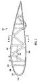
- FIG. 2 is a side cross-sectional view of a truss rib assembly 102 in accordance with an exemplary embodiment of the disclosure.
- a truss rib assembly 102 comprises a composite truss structure.
- Truss rib assembly 102 includes an upper chord member 202, a lower chord member, 204, and a plurality of web members 206 extending therebetween.
- Each of upper chord member 202, lower chord member, 204, and web members 206 are formed of a continuous composite fiber wound through each of upper chord member 202, lower chord member 204, and web members 206.
- a number of passes or turns of the continuous composite fiber that are channeled through each member is determined based on a strength requirement of each member and based on the strength capability of each continuous composite fiber and the strength capability of the determined number of continuous composite fibers channeled through each member.
- the continuous composite fiber may comprise, but is not limited to a carbon fiber, a fiber glass fiber, an aromatic polyamide fiber such as Aramid, other fiber filaments or combinations thereof.
- the continuous composite fiber may also comprise, but is not limited to, a tow, or a web comprising the above materials.
- the fiber, web or tow may be impregnated with an adhesive, a thermoplastic or a thermoset.
- upper chord member 202 and lower chord member 204 are joined at leading edge 108 and trialing edge 110.
- upper chord member 202, lower chord member 204 are not joined directly and may be joined through web member 206 extending between upper chord member 202 spaced apart from lower chord member 204.
- Truss rib assembly 102 also includes a first rib side or gusseting plate 208 coupled to upper chord member 202, lower chord member 204, and web members 206, and a second rib side or gusseting plate 210 (not visible on the backside of truss rib 102 in figure 2 ) coupled to a side of upper chord member 202, lower chord member, 204, and web members 206 opposite from first gusseting plate 208.
- First gusseting plate 208 and second gusseting plate 210 sandwich upper chord member 202, lower chord member 204, and web members 206 therebetween.
- First gusseting plate 208 and second gusseting plate 210 may also include a flange 212 extending away from an outer peripheral edge 214 of the respective gusseting plate 208 and 210.
- Flange 212 increase a stiffness of truss rib assembly 102 and provides a coupling location for attaching lower wing skin 116 and upper wing skin 118 (both shown in Figure 1 ).
- gusseting plates 208 and 210 are routed or machined to open up the webs of gusseting plates 208 and 210 to conform a profile of gusseting plates 208 and 210 to a profile of upper chord member 202, lower chord member 204, and web members 206 and to reduce the weight of truss rib assembly 102.
- a form in a predetermined shape of truss rib assembly 102 is formed using a channeled frame.
- a continuous fiber generally of a composite material such as carbon filament is wound through the channel a predetermined number of passes through each structural element based on a strength requirement of each respective structural element.
- the continuous fiber may include, but is not limited to fibers, filaments, webs, and tapes including carbon or other material.
- the fibers, filaments, webs, and tapes may also be impregnated with an adhesive, thermoplastic, or thermoset such as for example an epoxy.
- the fiber is wound through the channels representing the various structural elements forming truss rib assembly 102. More passes of the fiber through a structural elements generally permits that structural element to withstand greater load.
- the load carrying requirement of each structural element is determined and this requirement is associated with a number of turns or passes to achieve that load carrying capability.
- gusseting plates 208 and 210 are coupled to a side of truss rib assembly 102 to provide additional stiffness and an attachment means for, for example, a skin of the airfoil or deck of a bridge.
- truss rib assembly 102 is a composite rib that is fiber placed with side plates co-bonded, bonded or consolidated, if thermoplastic, to the side of the rib. A continuous fiber is placed down following and outlining the rib mold line and the truss structural members. This process is continued until the rib is of sufficient thickness to carry the appropriate wing design loads. The fiber placement of the ribs allows each rib to be tailored optimizing the structural design and reducing the weight of the wing assembly. The side plates are then added, one to each side of the rib to act as gussets at the junction of each of the truss structural elements.
- Truss rib assembly 102 is illustrated as if manufactured as a complete truss rib assembly 102 but the option exists to manufacture truss rib assembly 102 in more than one piece to facilitate different wing assembly methods.
- the flanges shown at the spar and cap locations are to bond the rib and or rib sections to the individual skins to form skin assemblies and then bond the subassemblies into a completed wing.
- the use of the composite truss ribs are not limited to aircraft wings, but also to floor or roof trusses on buildings, and bridge trusses that are manufactured in different locations and are erected on site. The light weight truss simplifies handling with less or smaller support equipment.
- FIG 3 is a section view of truss rib assembly 102 taken along section lines A-A (shown in Figure 2 ).
- truss rib assembly 102 is formed by a plurality of passes or turns of a continuous fiber 302 wound about a form or frame to the shape of the desired truss rib assembly 102.
- the passes of fiber are substantially unidirectional and are adhered or bonded together to form a rigid truss comprising upper chord 202, of which only a portion is shown in Figure 3 .
- Figure 4 is a section view of truss rib assembly 102 taken along section lines B-B (shown in Figure 2 ).
- truss rib assembly 102 is formed by a plurality of passes or turns of a continuous fiber 302 wound about a form or frame to the shape of the desired truss rib assembly 102.
- the passes of fiber are substantially unidirectional and are adhered or bonded together to form a rigid truss comprising upper chord 202 and lower chord 204, of which only a portion of each is shown in Figure 4 .
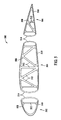
- FIG. 5 is a side cross-sectional view of a truss rib assembly 500 in accordance with another exemplary embodiment of the disclosure.
- truss rib assembly 500 is fabricated in three portions, a forward portion 502, a center portion 504, and an aft portion 506.
- Each portion is formed of a continuous fiber wound in channels oriented in a pattern representing a respective portion of an upper chord 508, a lower chord 510, and interconnecting structural members 512 forming the truss web.
- Each portion includes at least one fabrication channel 514 coupled to a distal end of respective portions of upper chord 508 and lower chord 510.
- Fabrication channel 514 permits winding a continuous fiber through all members of forward portion 502, a center portion 504, and an aft portion 506 during fabrication. Fabrication channel 514 is removed from forward portion 502, a center portion 504, and an aft portion 506 after formation of forward portion 502, a center portion 504, and an aft portion 506 is complete and further assembly is accomplished by joining forward portion 502, a center portion 504, and an aft portion 506. In one embodiment, forward portion 502 and center portion 504 are assembled to a forward spar (not shown) prior to being joined to each other and center portion 504 and an aft portion 506 are assembled to a rear spar (not shown) prior to being joined to each other.
- the above-described methods of forming composite structural members and composite truss structures formed thereby are cost-effective and highly reliable.
- the methods and structures include a continuous fiber wound through a plurality of structural elements to form the member. The fiber is placed such that it is substantially unidirectional along a longitudinal axis in each of the elements to provide lightweight compressive and tensile strength to the member. Accordingly, the methods and structures facilitate reducing weight and fabrication time, and improving strength and stiffness of the structural member in a cost-effective and reliable manner.
Landscapes
- Engineering & Computer Science (AREA)
- Mechanical Engineering (AREA)
- Aviation & Aerospace Engineering (AREA)
- Rod-Shaped Construction Members (AREA)
- Moulding By Coating Moulds (AREA)
Claims (15)
- Verbund-Verstärkungsspant für eine Flugzeug-Tragfläche, mit:einem oberen Sehnenelement (202),einem unteren Sehnenelement (204),mehreren Stegelementen (206), die sich dazwischen erstrecken, wobei das obere Sehnenelement, das untere Sehnenelement und die mehreren Stegelemente alle aus einer kontinuierlichen Verbundfaser geformt sind, die in jedem, dem oberen Sehnenelement, dem unteren Sehnenelement und den mehreren Stegelementen, angeordnet ist, wobei das obere Sehnenelement, das untere Sehnenelement und die mehreren Stegelemente alle eine vorbestimmte Anzahl von Umläufen der kontinuierlichen Verbundfaser enthalten, die einer vorbestimmten Belastung entspricht, undwenigstens einer ersten Versteifungsplatte (208), die an das obere Sehnenelement, das untere Sehnenelement und die mehreren Stegelemente gekoppelt ist.
- Spant nach Anspruch 1, der ferner eine zweite Versteifungsplatte (210) enthält, die an eine Seite des oberen Sehnenelements (202), des unteren Sehnenelements (204) und der mehreren Stegelemente (206), gegenüber der ersten Versteifungsplatte (208), gekoppelt ist, wobei die erste Versteifungsplatte und die zweite Versteifungsplatte zwischen ihnen das obere Sehnenelement, das untere Sehnenelement und die mehreren Stegelemente sandwichartig einschließen.
- Spant nach Anspruch 1, wobei die wenigstens eine erste Versteifungsplatte (208) einen Flansch (212) enthält, der sich von einer Kante der jeweiligen Versteifungsplatte weg erstreckt.
- Spant nach Anspruch 1, wobei eine Anzahl von Faser-Umläufen durch jedes Element auf der Grundlage einer an das Element anzulegenden Belastung bestimmt wird.
- Spant nach Anspruch 1, wobei ein Profil wenigstens einer der Platten zu einem Profil des oberen Sehnenelements (202), des unteren Sehnenelements (204) und der mehreren Stegelemente (206) komplementär ist.
- Spant nach Anspruch 1, wobei die mehreren Stegelemente (206) wenigstens eines von einem vertikalen Stegelement, einem horizontalen Stegelement und einem diagonalen Stegelement enthalten.
- Spant nach Anspruch 1, wobei wenigstens eines von dem oberen Sehnenelement (202), dem unteren Sehnenelement (204) und den mehreren Stegelementen (206) wenigstes eines von einem epoxidimprägnierten Kohlenstoff-Filament, einem epoxidimprägnierten Kohlenstoff-Seil und einer epoxidimprägnierten Kohlenstoff-Gewebe enthält.
- Spant nach Anspruch 1, wobei ein erstes Ende des oberen Sehnenelements (202) an ein erstes Ende des unteren Sehnenelements (204) gekoppelt ist und ein zweites Ende des oberen Sehnenelements an ein zweites Ende des unteren Sehnenelements gekoppelt ist.
- Spant nach Anspruch 1, wobei ein erster Abschnitt des Spants gesondert von einem zweiten Abschnitt des Spants geformt ist, wobei der erste und der zweite Abschnitt aneinander gekoppelt sind, um den Spant zu bilden.
- Verfahren zum Formen eines Verbund-Verstärkungsspants für eine Flugzeug-Tragfläche, enthaltend:das Formen eines Profils des Spants, wobei das Profil einen Kanal einschließt, der miteinander verbundene Strukturelemente darstellt, die Folgendes enthalten:ein oberes Sehnenelement (202),ein unteres Sehnenelement (204) undmehrere Stegelemente (206), die sich dazwischen erstrecken,das Wickeln einer durchgehenden Faser durch den Kanal für eine vorbestimmte Anzahl von Umläufen durch jedes Strukturelement auf der Grundlage einer Festigkeitsanforderung jedes jeweiligen Strukturelements unddas Koppeln wenigstens einer ersten Versteifungsplatte (208) an die miteinander verbundenen Strukturelemente.
- Verfahren nach Anspruch 10, das ferner das Koppeln einer zweiten Versteifungsplatte (210) an eine Seite der miteinander verbundenen Strukturelemente, gegenüber der ersten Versteifungsplatte, enthält.
- Verfahren nach Anspruch 10, wobei das Formen eines Profils des Strukturelements das Formen eines Profils enthält, das Kanäle einschließt, die wenigstens eines von einem vertikalen Stegelement, einem horizontalen Stegelement und einem diagonalen Stegelement darstellen.
- Verfahren nach Anspruch 10, wobei das Wickeln einer durchgehenden Faser durch den Kanal das Wickeln wenigstes eines von einem epoxidimprägnierten Kohlenstoff-Filament, eine epoxidimprägnierten Kohlenstoff-Seil und einem epoxidimprägnierten Kohlenstoff-Gewebe durch den Kanal enthält, um die Strukturelemente zu formen.
- Verfahren nach Anspruch 10, wobei das Koppeln wenigstens einer ersten Versteifungsplatte (208) an die miteinander verbundenen Strukturelemente das Koppeln wenigstens einer Versteifungsplatte enthält, die einen Flansch (212) einschließt, der sich von einer Kante einer jeweiligen der wenigstens einen Versteifungsplatte weg erstreckt.
- Verfahren nach Anspruch 10, wobei das Koppeln wenigstens einer ersten Versteifungsplatte (208) an die miteinander verbundenen Strukturelemente das Koppeln wenigstens einer Versteifungsplatte enthält, die ein Profil hat, das im Wesentlichen zu einem Profil der miteinander verbundenen Strukturelemente komplementär ist.
Applications Claiming Priority (2)
| Application Number | Priority Date | Filing Date | Title |
|---|---|---|---|
| US11/696,793 US7954763B2 (en) | 2007-04-05 | 2007-04-05 | Methods and systems for composite structural truss |
| PCT/US2008/058796 WO2008124351A2 (en) | 2007-04-05 | 2008-03-29 | Methods and systems for composite structural truss |
Publications (2)
| Publication Number | Publication Date |
|---|---|
| EP2139762A2 EP2139762A2 (de) | 2010-01-06 |
| EP2139762B1 true EP2139762B1 (de) | 2012-03-07 |
Family
ID=39735176
Family Applications (1)
| Application Number | Title | Priority Date | Filing Date |
|---|---|---|---|
| EP08780500A Active EP2139762B1 (de) | 2007-04-05 | 2008-03-29 | Verfahren und systeme für einen verbundstrukturträger |
Country Status (5)
| Country | Link |
|---|---|
| US (2) | US7954763B2 (de) |
| EP (1) | EP2139762B1 (de) |
| CN (1) | CN101674979B (de) |
| AT (1) | ATE548258T1 (de) |
| WO (1) | WO2008124351A2 (de) |
Cited By (1)
| Publication number | Priority date | Publication date | Assignee | Title |
|---|---|---|---|---|
| US10569859B2 (en) | 2016-04-11 | 2020-02-25 | Asco Industries NV | High-lift device |
Families Citing this family (30)
| Publication number | Priority date | Publication date | Assignee | Title |
|---|---|---|---|---|
| US8424805B2 (en) * | 2009-10-07 | 2013-04-23 | Donald Smith | Airfoil structure |
| EP2330294B1 (de) * | 2009-12-02 | 2013-01-16 | Bladena ApS | Verstärkter, flügelförmiger Körper |
| DE102010010168B4 (de) * | 2010-03-03 | 2013-09-19 | Airbus Operations Gmbh | Verstrebungsanordnung zur Stabilisierung der Außenhaut eines aerodynamischen Flugzeugteils bei einem Verkehrsflugzeug |
| DE102010043850A1 (de) * | 2010-11-12 | 2012-05-16 | Airbus Operations Gmbh | Strukturelement für ein Luft- und/oder Raumfahrzeug und Verfahren zum Herstellen eines derartigen Strukturelementes |
| GB201020189D0 (en) * | 2010-11-29 | 2011-01-12 | Airbus Uk Ltd | An aircraft structure |
| US20130064677A1 (en) * | 2011-09-13 | 2013-03-14 | General Electric Company | Rotor blade assembly for wind turbine |
| US9156559B2 (en) * | 2011-10-19 | 2015-10-13 | The Boeing Company | Segmented aircraft wing having solar arrays |
| CN102505638A (zh) * | 2011-11-08 | 2012-06-20 | 赵启武 | 一种主承力树脂基复合材料-钢桁组合结构制备方法 |
| US20160009368A1 (en) * | 2013-02-28 | 2016-01-14 | The Boeing Company | Composite laminated plate having reduced crossply angle |
| CN103287588B (zh) * | 2013-04-25 | 2016-01-06 | 上海卫星工程研究所 | 高承载能力内埋框架复合材料结构板 |
| US10479475B2 (en) * | 2013-08-09 | 2019-11-19 | The Boeing Company | Composite stringer beam joint structure of an aircraft |
| RU2544067C1 (ru) * | 2014-01-17 | 2015-03-10 | Открытое акционерное общество "Обнинское научно-производственное предприятие "Технология" | Способ изготовления профилированной ферменной конструкции из волокнистого композиционного материала |
| US10196126B2 (en) | 2015-04-07 | 2019-02-05 | The Boeing Company | Rib structure and method of forming thereof |
| EP3150484B1 (de) * | 2015-09-29 | 2018-12-12 | Airbus Operations, S.L. | Verbundrippe für einen torsionskasten eines luftfahrzeugs und herstellungsverfahren dafür |
| US10717512B2 (en) * | 2016-11-03 | 2020-07-21 | Continuous Composites Inc. | Composite vehicle body |
| US10850826B2 (en) | 2017-03-24 | 2020-12-01 | The Boeing Company | Aircraft wing space frame |
| CN107651163B (zh) * | 2017-10-23 | 2023-06-20 | 重庆通用航空产业集团有限公司 | 一种固定翼无人机外翼结构及其制作方法 |
| EP3498591A1 (de) * | 2017-12-13 | 2019-06-19 | AIRBUS HELICOPTERS DEUTSCHLAND GmbH | Gitterträger aus kompositmaterial mit einer sandwichgurtung |
| CN110386244A (zh) * | 2018-04-20 | 2019-10-29 | 北京京东尚科信息技术有限公司 | 无人机机翼骨架及包含其的无人机机翼、无人机 |
| CN109813518A (zh) * | 2019-01-23 | 2019-05-28 | 上海核工程研究设计院有限公司 | 一种翼栅叶片结构及其制备方法 |
| CN110005058B (zh) * | 2019-04-26 | 2024-12-10 | 中建钢构有限公司 | 桁架连接节点、桁架结构及屋盖 |
| EP3798115A1 (de) * | 2019-09-25 | 2021-03-31 | Formtech Composites Ltd. | Flügelrippe |
| US11046420B2 (en) * | 2019-10-23 | 2021-06-29 | The Boeing Company | Trailing edge flap having a waffle grid interior structure |
| CN112849436B (zh) * | 2021-02-25 | 2023-02-03 | 北京卫星制造厂有限公司 | 一种碳纤维复合材料桁架肋及其制备方法 |
| US12157572B2 (en) * | 2021-08-31 | 2024-12-03 | The Boeing Company | Method of making a control surface |
| US11987353B2 (en) | 2022-04-19 | 2024-05-21 | The Boeing Company | Thermoplastic skin panels, torque box and method |
| KR20240148146A (ko) * | 2023-04-03 | 2024-10-11 | 현대자동차주식회사 | 날개 프레임 및 이를 포함하는 비행기 |
| KR20240148479A (ko) * | 2023-04-04 | 2024-10-11 | 현대자동차주식회사 | 동체의 날개 하중 지지구조 |
| EP4552972B1 (de) * | 2023-11-07 | 2026-03-25 | Airbus Operations, S.L.U. | Doppel-y-förmiger holm aus verbundwerkstoff |
| CN117799817B (zh) * | 2024-02-26 | 2024-05-07 | 中国科学院工程热物理研究所 | 桁架式机翼结构、装配方法及桁架式梁的制备方法 |
Citations (1)
| Publication number | Priority date | Publication date | Assignee | Title |
|---|---|---|---|---|
| WO2001057354A2 (en) * | 2000-01-21 | 2001-08-09 | Chapman W Cullen Jr | Tubular members integrated to form a structure |
Family Cites Families (29)
| Publication number | Priority date | Publication date | Assignee | Title |
|---|---|---|---|---|
| US582527A (en) * | 1897-05-11 | Dominic golden | ||
| US1429600A (en) * | 1918-11-21 | 1922-09-19 | American Balsa Company Inc | Beam structure |
| US2233969A (en) * | 1938-12-30 | 1941-03-04 | Bell Aircraft Corp | Pressed wing rib |
| US2589193A (en) * | 1946-11-29 | 1952-03-11 | Goodyear Aircraft Corp | Airfoil, and particularly helicopter blade |
| US3901465A (en) * | 1974-03-05 | 1975-08-26 | Lawrence J Deangelis | Variable-area variable incidence wing and aircraft incorporating same |
| GB1534697A (en) * | 1975-03-27 | 1978-12-06 | Heath Charles William | Model aircraft wing construction jig |
| US4002116A (en) * | 1975-05-09 | 1977-01-11 | Jack N. Schmitt | Apparatus for forming trusses |
| US4051289A (en) * | 1976-04-12 | 1977-09-27 | General Electric Company | Composite airfoil construction |
| US4120065A (en) * | 1977-12-15 | 1978-10-17 | Eugene W. Sivachenko | Lightweight modular, truss-deck bridge system |
| US4223053A (en) * | 1978-08-07 | 1980-09-16 | The Boeing Company | Truss core panels |
| US4481703A (en) * | 1980-02-25 | 1984-11-13 | Rockwell International Corporation | Method of making rib structures for an airfoil |
| US4671470A (en) * | 1985-07-15 | 1987-06-09 | Beech Aircraft Corporation | Method for fastening aircraft frame elements to sandwich skin panels covering same using woven fiber connectors |
| US5332178A (en) * | 1992-06-05 | 1994-07-26 | Williams International Corporation | Composite wing and manufacturing process thereof |
| GB9215827D0 (en) * | 1992-07-24 | 1992-09-09 | British Aerospace | A lightning shield |
| US5375324A (en) * | 1993-07-12 | 1994-12-27 | Flowind Corporation | Vertical axis wind turbine with pultruded blades |
| US5632940A (en) * | 1994-03-29 | 1997-05-27 | Whatley; Bradford L. | Method of making an integrally stiffened article |
| RU2116934C1 (ru) * | 1997-05-06 | 1998-08-10 | Акционерное общество "Центр перспективных разработок акционерного общества "Центральный научно-исследовательский институт специального машиностроения" | Нервюра из композиционных материалов (варианты) и устройство для изготовления ее плоской реберно-ячеистой структуры |
| DE19922295C1 (de) * | 1999-05-14 | 2000-07-27 | Eurocopter Deutschland | Unterbodenstruktur einer Rumpfzelle eines Luftfahrzeuges |
| US6513757B1 (en) * | 1999-07-19 | 2003-02-04 | Fuji Jukogyo Kabushiki Kaisha | Wing of composite material and method of fabricating the same |
| US6889937B2 (en) * | 1999-11-18 | 2005-05-10 | Rocky Mountain Composites, Inc. | Single piece co-cure composite wing |
| JP4416900B2 (ja) * | 2000-03-10 | 2010-02-17 | 富士重工業株式会社 | 複合材パネルおよびその製造方法 |
| MXPA03000732A (es) * | 2000-07-28 | 2003-07-14 | Univ Brigham Young | Estructura armada isometrica. |
| US6638466B1 (en) * | 2000-12-28 | 2003-10-28 | Raytheon Aircraft Company | Methods of manufacturing separable structures |
| US6945727B2 (en) * | 2002-07-19 | 2005-09-20 | The Boeing Company | Apparatuses and methods for joining structural members, such as composite structural members |
| CA2456321A1 (en) * | 2003-01-30 | 2004-07-30 | Martin Bureau | Laminated polymer composite material |
| US20060032702A1 (en) * | 2004-07-29 | 2006-02-16 | Oshkosh Truck Corporation | Composite boom assembly |
| SG120189A1 (en) * | 2004-08-27 | 2006-03-28 | Offshore Technology Dev Pte Lt | Brace assembly for truss legs of offshore structures |
| JP4568906B2 (ja) * | 2004-12-16 | 2010-10-27 | 独立行政法人 宇宙航空研究開発機構 | 飛行体用翼、飛行体用翼複合材およびその製造方法 |
| US7575194B2 (en) * | 2006-11-30 | 2009-08-18 | The Boeing Company | Apparatuses and methods for joining composite members and other structural members in aircraft wing boxes and other structures |
-
2007
- 2007-04-05 US US11/696,793 patent/US7954763B2/en active Active
-
2008
- 2008-03-29 WO PCT/US2008/058796 patent/WO2008124351A2/en not_active Ceased
- 2008-03-29 AT AT08780500T patent/ATE548258T1/de active
- 2008-03-29 EP EP08780500A patent/EP2139762B1/de active Active
- 2008-03-29 CN CN2008800142594A patent/CN101674979B/zh active Active
-
2011
- 2011-04-26 US US13/094,240 patent/US8074929B1/en active Active
Patent Citations (1)
| Publication number | Priority date | Publication date | Assignee | Title |
|---|---|---|---|---|
| WO2001057354A2 (en) * | 2000-01-21 | 2001-08-09 | Chapman W Cullen Jr | Tubular members integrated to form a structure |
Cited By (1)
| Publication number | Priority date | Publication date | Assignee | Title |
|---|---|---|---|---|
| US10569859B2 (en) | 2016-04-11 | 2020-02-25 | Asco Industries NV | High-lift device |
Also Published As
| Publication number | Publication date |
|---|---|
| WO2008124351A3 (en) | 2009-03-05 |
| US7954763B2 (en) | 2011-06-07 |
| US20080245927A1 (en) | 2008-10-09 |
| CN101674979A (zh) | 2010-03-17 |
| CN101674979B (zh) | 2013-04-24 |
| WO2008124351A2 (en) | 2008-10-16 |
| EP2139762A2 (de) | 2010-01-06 |
| US8074929B1 (en) | 2011-12-13 |
| ATE548258T1 (de) | 2012-03-15 |
Similar Documents
| Publication | Publication Date | Title |
|---|---|---|
| EP2139762B1 (de) | Verfahren und systeme für einen verbundstrukturträger | |
| US8490362B2 (en) | Methods and systems for composite structural truss | |
| US8079549B2 (en) | Monolithic integrated structural panels especially useful for aircraft structures | |
| EP2301840B1 (de) | Integrierte luftfahrzeugsturktur aus verbundwerkstoff | |
| US6190484B1 (en) | Monolithic composite wing manufacturing process | |
| CN102958802A (zh) | 以复合材料制成的飞行器机身及制造方法 | |
| RU2602100C2 (ru) | Структура самолета для обеспечения высокой устойчивости к оттягиванию композитного стрингера | |
| US8943666B2 (en) | Method for assembling fuselage sections of an aircraft | |
| EP3415308B1 (de) | Verfahren zur montage eines flugzeugrumpfes | |
| RU2522538C2 (ru) | Конструкция узла герметической перегородки летательного аппарата | |
| US6110567A (en) | Composite structural panel having a face sheet reinforced with a channel stiffener grid | |
| CN103963956A (zh) | 用于承载负荷的箱式结构及其制造方法 | |
| US10940936B2 (en) | Stringer with plank ply and skin construction for aircraft | |
| CN103303459A (zh) | 立体框架结构 | |
| EP2781450B1 (de) | System und Verfahren zum Verbinden von Verbundstoffstrukturen miteinander | |
| EP2907654B1 (de) | Verbindungen in Fasermetalllaminaten | |
| US8418962B2 (en) | Distribution of point loads in honeycomb panels | |
| US20150251400A1 (en) | Integrated lamination process for manufacturing a shell element | |
| US8973870B2 (en) | Wall component for an aircraft | |
| CN206889425U (zh) | 蜂窝夹层结构等强度连接结构 | |
| US20250145273A1 (en) | Double y-shaped spar made of composite material |
Legal Events
| Date | Code | Title | Description |
|---|---|---|---|
| PUAI | Public reference made under article 153(3) epc to a published international application that has entered the european phase |
Free format text: ORIGINAL CODE: 0009012 |
|
| 17P | Request for examination filed |
Effective date: 20091022 |
|
| AK | Designated contracting states |
Kind code of ref document: A2 Designated state(s): AT BE BG CH CY CZ DE DK EE ES FI FR GB GR HR HU IE IS IT LI LT LU LV MC MT NL NO PL PT RO SE SI SK TR |
|
| 17Q | First examination report despatched |
Effective date: 20100705 |
|
| GRAP | Despatch of communication of intention to grant a patent |
Free format text: ORIGINAL CODE: EPIDOSNIGR1 |
|
| GRAS | Grant fee paid |
Free format text: ORIGINAL CODE: EPIDOSNIGR3 |
|
| GRAA | (expected) grant |
Free format text: ORIGINAL CODE: 0009210 |
|
| AK | Designated contracting states |
Kind code of ref document: B1 Designated state(s): AT BE BG CH CY CZ DE DK EE ES FI FR GB GR HR HU IE IS IT LI LT LU LV MC MT NL NO PL PT RO SE SI SK TR |
|
| DAX | Request for extension of the european patent (deleted) | ||
| REG | Reference to a national code |
Ref country code: GB Ref legal event code: FG4D |
|
| REG | Reference to a national code |
Ref country code: AT Ref legal event code: REF Ref document number: 548258 Country of ref document: AT Kind code of ref document: T Effective date: 20120315 Ref country code: CH Ref legal event code: EP |
|
| REG | Reference to a national code |
Ref country code: IE Ref legal event code: FG4D |
|
| REG | Reference to a national code |
Ref country code: DE Ref legal event code: R096 Ref document number: 602008013987 Country of ref document: DE Effective date: 20120503 |
|
| REG | Reference to a national code |
Ref country code: NL Ref legal event code: VDEP Effective date: 20120307 |
|
| PG25 | Lapsed in a contracting state [announced via postgrant information from national office to epo] |
Ref country code: NO Free format text: LAPSE BECAUSE OF FAILURE TO SUBMIT A TRANSLATION OF THE DESCRIPTION OR TO PAY THE FEE WITHIN THE PRESCRIBED TIME-LIMIT Effective date: 20120607 Ref country code: HR Free format text: LAPSE BECAUSE OF FAILURE TO SUBMIT A TRANSLATION OF THE DESCRIPTION OR TO PAY THE FEE WITHIN THE PRESCRIBED TIME-LIMIT Effective date: 20120307 Ref country code: NL Free format text: LAPSE BECAUSE OF FAILURE TO SUBMIT A TRANSLATION OF THE DESCRIPTION OR TO PAY THE FEE WITHIN THE PRESCRIBED TIME-LIMIT Effective date: 20120307 Ref country code: LT Free format text: LAPSE BECAUSE OF FAILURE TO SUBMIT A TRANSLATION OF THE DESCRIPTION OR TO PAY THE FEE WITHIN THE PRESCRIBED TIME-LIMIT Effective date: 20120307 |
|
| LTIE | Lt: invalidation of european patent or patent extension |
Effective date: 20120307 |
|
| PG25 | Lapsed in a contracting state [announced via postgrant information from national office to epo] |
Ref country code: GR Free format text: LAPSE BECAUSE OF FAILURE TO SUBMIT A TRANSLATION OF THE DESCRIPTION OR TO PAY THE FEE WITHIN THE PRESCRIBED TIME-LIMIT Effective date: 20120608 Ref country code: LV Free format text: LAPSE BECAUSE OF FAILURE TO SUBMIT A TRANSLATION OF THE DESCRIPTION OR TO PAY THE FEE WITHIN THE PRESCRIBED TIME-LIMIT Effective date: 20120307 Ref country code: FI Free format text: LAPSE BECAUSE OF FAILURE TO SUBMIT A TRANSLATION OF THE DESCRIPTION OR TO PAY THE FEE WITHIN THE PRESCRIBED TIME-LIMIT Effective date: 20120307 |
|
| REG | Reference to a national code |
Ref country code: AT Ref legal event code: MK05 Ref document number: 548258 Country of ref document: AT Kind code of ref document: T Effective date: 20120307 |
|
| PG25 | Lapsed in a contracting state [announced via postgrant information from national office to epo] |
Ref country code: CY Free format text: LAPSE BECAUSE OF FAILURE TO SUBMIT A TRANSLATION OF THE DESCRIPTION OR TO PAY THE FEE WITHIN THE PRESCRIBED TIME-LIMIT Effective date: 20120307 |
|
| PG25 | Lapsed in a contracting state [announced via postgrant information from national office to epo] |
Ref country code: MC Free format text: LAPSE BECAUSE OF NON-PAYMENT OF DUE FEES Effective date: 20120331 Ref country code: RO Free format text: LAPSE BECAUSE OF FAILURE TO SUBMIT A TRANSLATION OF THE DESCRIPTION OR TO PAY THE FEE WITHIN THE PRESCRIBED TIME-LIMIT Effective date: 20120307 Ref country code: SE Free format text: LAPSE BECAUSE OF FAILURE TO SUBMIT A TRANSLATION OF THE DESCRIPTION OR TO PAY THE FEE WITHIN THE PRESCRIBED TIME-LIMIT Effective date: 20120307 Ref country code: CZ Free format text: LAPSE BECAUSE OF FAILURE TO SUBMIT A TRANSLATION OF THE DESCRIPTION OR TO PAY THE FEE WITHIN THE PRESCRIBED TIME-LIMIT Effective date: 20120307 Ref country code: BE Free format text: LAPSE BECAUSE OF FAILURE TO SUBMIT A TRANSLATION OF THE DESCRIPTION OR TO PAY THE FEE WITHIN THE PRESCRIBED TIME-LIMIT Effective date: 20120307 Ref country code: PL Free format text: LAPSE BECAUSE OF FAILURE TO SUBMIT A TRANSLATION OF THE DESCRIPTION OR TO PAY THE FEE WITHIN THE PRESCRIBED TIME-LIMIT Effective date: 20120307 Ref country code: EE Free format text: LAPSE BECAUSE OF FAILURE TO SUBMIT A TRANSLATION OF THE DESCRIPTION OR TO PAY THE FEE WITHIN THE PRESCRIBED TIME-LIMIT Effective date: 20120307 Ref country code: IS Free format text: LAPSE BECAUSE OF FAILURE TO SUBMIT A TRANSLATION OF THE DESCRIPTION OR TO PAY THE FEE WITHIN THE PRESCRIBED TIME-LIMIT Effective date: 20120707 Ref country code: SI Free format text: LAPSE BECAUSE OF FAILURE TO SUBMIT A TRANSLATION OF THE DESCRIPTION OR TO PAY THE FEE WITHIN THE PRESCRIBED TIME-LIMIT Effective date: 20120307 |
|
| REG | Reference to a national code |
Ref country code: CH Ref legal event code: PL |
|
| PG25 | Lapsed in a contracting state [announced via postgrant information from national office to epo] |
Ref country code: SK Free format text: LAPSE BECAUSE OF FAILURE TO SUBMIT A TRANSLATION OF THE DESCRIPTION OR TO PAY THE FEE WITHIN THE PRESCRIBED TIME-LIMIT Effective date: 20120307 Ref country code: PT Free format text: LAPSE BECAUSE OF FAILURE TO SUBMIT A TRANSLATION OF THE DESCRIPTION OR TO PAY THE FEE WITHIN THE PRESCRIBED TIME-LIMIT Effective date: 20120709 |
|
| REG | Reference to a national code |
Ref country code: IE Ref legal event code: MM4A |
|
| PLBE | No opposition filed within time limit |
Free format text: ORIGINAL CODE: 0009261 |
|
| STAA | Information on the status of an ep patent application or granted ep patent |
Free format text: STATUS: NO OPPOSITION FILED WITHIN TIME LIMIT |
|
| PG25 | Lapsed in a contracting state [announced via postgrant information from national office to epo] |
Ref country code: LI Free format text: LAPSE BECAUSE OF NON-PAYMENT OF DUE FEES Effective date: 20120331 Ref country code: CH Free format text: LAPSE BECAUSE OF NON-PAYMENT OF DUE FEES Effective date: 20120331 Ref country code: DK Free format text: LAPSE BECAUSE OF FAILURE TO SUBMIT A TRANSLATION OF THE DESCRIPTION OR TO PAY THE FEE WITHIN THE PRESCRIBED TIME-LIMIT Effective date: 20120307 Ref country code: IE Free format text: LAPSE BECAUSE OF NON-PAYMENT OF DUE FEES Effective date: 20120329 Ref country code: AT Free format text: LAPSE BECAUSE OF FAILURE TO SUBMIT A TRANSLATION OF THE DESCRIPTION OR TO PAY THE FEE WITHIN THE PRESCRIBED TIME-LIMIT Effective date: 20120307 |
|
| 26N | No opposition filed |
Effective date: 20121210 |
|
| PG25 | Lapsed in a contracting state [announced via postgrant information from national office to epo] |
Ref country code: IT Free format text: LAPSE BECAUSE OF FAILURE TO SUBMIT A TRANSLATION OF THE DESCRIPTION OR TO PAY THE FEE WITHIN THE PRESCRIBED TIME-LIMIT Effective date: 20120307 |
|
| REG | Reference to a national code |
Ref country code: DE Ref legal event code: R097 Ref document number: 602008013987 Country of ref document: DE Effective date: 20121210 |
|
| PG25 | Lapsed in a contracting state [announced via postgrant information from national office to epo] |
Ref country code: ES Free format text: LAPSE BECAUSE OF FAILURE TO SUBMIT A TRANSLATION OF THE DESCRIPTION OR TO PAY THE FEE WITHIN THE PRESCRIBED TIME-LIMIT Effective date: 20120618 |
|
| PG25 | Lapsed in a contracting state [announced via postgrant information from national office to epo] |
Ref country code: BG Free format text: LAPSE BECAUSE OF FAILURE TO SUBMIT A TRANSLATION OF THE DESCRIPTION OR TO PAY THE FEE WITHIN THE PRESCRIBED TIME-LIMIT Effective date: 20120607 Ref country code: MT Free format text: LAPSE BECAUSE OF FAILURE TO SUBMIT A TRANSLATION OF THE DESCRIPTION OR TO PAY THE FEE WITHIN THE PRESCRIBED TIME-LIMIT Effective date: 20120307 |
|
| PG25 | Lapsed in a contracting state [announced via postgrant information from national office to epo] |
Ref country code: TR Free format text: LAPSE BECAUSE OF FAILURE TO SUBMIT A TRANSLATION OF THE DESCRIPTION OR TO PAY THE FEE WITHIN THE PRESCRIBED TIME-LIMIT Effective date: 20120307 |
|
| PG25 | Lapsed in a contracting state [announced via postgrant information from national office to epo] |
Ref country code: LU Free format text: LAPSE BECAUSE OF NON-PAYMENT OF DUE FEES Effective date: 20120329 |
|
| PG25 | Lapsed in a contracting state [announced via postgrant information from national office to epo] |
Ref country code: HU Free format text: LAPSE BECAUSE OF FAILURE TO SUBMIT A TRANSLATION OF THE DESCRIPTION OR TO PAY THE FEE WITHIN THE PRESCRIBED TIME-LIMIT Effective date: 20080329 |
|
| REG | Reference to a national code |
Ref country code: FR Ref legal event code: PLFP Year of fee payment: 9 |
|
| REG | Reference to a national code |
Ref country code: FR Ref legal event code: PLFP Year of fee payment: 10 |
|
| REG | Reference to a national code |
Ref country code: FR Ref legal event code: PLFP Year of fee payment: 11 |
|
| REG | Reference to a national code |
Ref country code: DE Ref legal event code: R082 Ref document number: 602008013987 Country of ref document: DE Representative=s name: SCHIWECK WEINZIERL KOCH PATENTANWAELTE PARTNER, DE |
|
| P01 | Opt-out of the competence of the unified patent court (upc) registered |
Effective date: 20230516 |
|
| PGFP | Annual fee paid to national office [announced via postgrant information from national office to epo] |
Ref country code: GB Payment date: 20260327 Year of fee payment: 19 |
|
| PGFP | Annual fee paid to national office [announced via postgrant information from national office to epo] |
Ref country code: DE Payment date: 20260327 Year of fee payment: 19 |
|
| PGFP | Annual fee paid to national office [announced via postgrant information from national office to epo] |
Ref country code: FR Payment date: 20260325 Year of fee payment: 19 |