EP2139751B1 - Seating structure made of natural composite material and process for making same - Google Patents
Seating structure made of natural composite material and process for making same Download PDFInfo
- Publication number
- EP2139751B1 EP2139751B1 EP08710037A EP08710037A EP2139751B1 EP 2139751 B1 EP2139751 B1 EP 2139751B1 EP 08710037 A EP08710037 A EP 08710037A EP 08710037 A EP08710037 A EP 08710037A EP 2139751 B1 EP2139751 B1 EP 2139751B1
- Authority
- EP
- European Patent Office
- Prior art keywords
- seating structure
- base element
- composite material
- base
- shell
- Prior art date
- Legal status (The legal status is an assumption and is not a legal conclusion. Google has not performed a legal analysis and makes no representation as to the accuracy of the status listed.)
- Active
Links
Images
Classifications
-
- B—PERFORMING OPERATIONS; TRANSPORTING
- B62—LAND VEHICLES FOR TRAVELLING OTHERWISE THAN ON RAILS
- B62J—CYCLE SADDLES OR SEATS; AUXILIARY DEVICES OR ACCESSORIES SPECIALLY ADAPTED TO CYCLES AND NOT OTHERWISE PROVIDED FOR, e.g. ARTICLE CARRIERS OR CYCLE PROTECTORS
- B62J1/00—Saddles or other seats for cycles; Arrangement thereof; Component parts
Definitions
- the present invention is applicable to the art of sport and leisure accessories and particularly relates to a seating structure made of natural composite material, and a process for making same.
- Bicycle saddles and the like are known to comprise a shell having an underside designed to face towards a bicycle frame and a topside designed to face towards a seated user.
- Comfort elements of the saddle such as inserts of elastomer, foam or gel and/or cover elements for contact with the seated user are generally attached to the top of the shell.
- Bicycle saddle shells are generally formed of a polymeric material such as polypropylene, polyamide, polybutadiene terephthalate or the like. While such polymeric material provides the advantages of having a light weight and a low cost, it exhibits no particularly high mechanical performances.
- the object of the present invention is to overcome the above drawbacks, by providing a seating structure that is highly efficient and relatively cost-effective.
- a particular object is to provide a seating structure that has a relatively low environmental impact.
- a further object of the invention is to provide a seat making process that has a relatively low environmental impact.
- composite material and derivatives thereof shall be meant to indicate a material comprising a thermoplastic or thermosetting polymeric matrix with a fibrous reinforcement embedded therein.
- natural fibers and derivatives thereof shall be meant to indicate fibers of animal or plant origin.
- the invention relates to a process for making the above seating structure, as defined in claim 11.
- the seating structure of the invention is embodied herein by a bicycle saddle having an elongate front portion and a widened rear portion for supporting a user. Nonetheless, it will be understood that the seating structure 1 may be configured as a seat, a seating surface of a chair or any other human body support.
- the structure 1 is essentially comprised of a load-bearing shell 2 and a cover element 3 thereon, for contact with a user.
- the seat 1 may further comprise rails 4 or the like for connection to a bicycle frame, not shown but well known per se.
- the shell 2 comprises at least one first base element 5 made from a composite material composed of a thermoplastic or thermosetting synthetic polymeric matrix and a reinforcement containing natural fibers, such as wool, cotton, linen, jute fibers.
- the seating structure of the invention has a lower environmental impact as compared to prior art saddles.
- the natural fiber-containing composite material is much more easily recyclable than traditional composite materials.
- the technical characteristics of the base element 5 as mentioned below shall be generally intended to designate from time to time one or more of the base elements 5, 5', ... of the shell 2.
- the natural fibers may be of the woven and/or nonwoven type and may be combined with polymeric and/or synthetic and/or metal fibers for reinforcing the base element 5.
- the composite material of the latter may be also filled with nanoparticles, that can be of metal and/or mineral and/or polymeric types.
- the synthetic polymeric matrix of the composite material that forms the base element 5 is of thermoplastic type, preferably in fiber form at ambient temperature.
- Such fibers may be selected, for example, from the group comprising: polypropylene, polyamide, polybutadiene terephthalate, polyethylene, polystyrene.
- the polymeric matrix may be provided in other states, e.g. in granules, without departure from the inventive scope as defined in the annexed claims.
- the shell 2 includes at least one substantially sheet-like stiffening element, preferably made of metal, laid on the base element 5 to improve the mechanical properties of the shell 2.
- the shell 2 of the saddle 1 may also consist of the first base element 5 only, without departure from the inventive scope as defined in the annexed claims.
- the stiffening element 6 may be formed of any material, such as a traditional composite, i.e. carbon fiber, glass, Kevlar® or the like, without departure from the inventive scope as defined in the annexed claims.
- the base element 5 may include at least one differential deformable portion, generally designated by numeral 7.
- the saddle will have stiffer areas, designated by numerals 8, 8', which will contribute to the increase of its mechanical strength, and more resilient areas, defined by the differential deformable portions 7, for improved user comfort.
- the term "differential deformable portion" or the like shall be meant to indicate an area within the surface of the seat 1 that, under a load, has a considerably lower deformability than at least another area within the same surface under the same load.
- the differential deformable portion 7 may be located in the ischial and/or prostatic and/or peripheral zones of the saddle, thereby defining high user comfort areas in the regions of the body that are more susceptible to injury and pain during exercise.
- one or more differential deformable portions 7 may be provided at the contact points between the seat 1 and the inner thigh of a user.
- the stiffening element 6 may have at least one aperture 9 coincident with the more deformable portions 7, to allow contact of the user with the more comfortable areas.
- At least one insert 20 of a viscoelastic material or the like may be interposed between the cover element 3 and the shell 2, as shown in Figure 3 and attached thereto.
- the base element 5 may be formed by thermoforming at least one sheet element 10 from the composite material consisting of the synthetic polymeric matrix and the natural fiber-containing reinforcement in a specially designed mold 11.
- a sheet element 10 may be used that is formed of jute fibers dispersed in a polypropylene fiber matrix.
- the sheet element 10 may be laid in the mold 11, compressed between the male and female parts 12, 13 thereof and heated to a temperature near the melting or setting temperature of the matrix of the composite material, depending on whether such matrix is of the thermoplastic or thermosetting type. As an indication, such temperature may be in a range from 150°C to 300°C, according to the type of matrix being used.
- the sheet element 10 changes from its initial height H1 to a final height H2 defined by the distance between the male and female parts 12, 13 of the mold 11. It will be understood that the ratio between the heights H1/H2 will determine the compression ratio of the sheet element 10 so that, as the H1/H2 compression ratio increases the base element 5 will have an increasing stiffness.
- the differential deformable portions 7 of the base element 5 may be obtained by differential compression of the base element 5 between the male and female parts 12, 13 of the mold 11, to create areas with different compression ratios.
- At least one layer 10' may be laid on the sheet element 10, preferably made of the same composite material as the sheet element 10, and having at least one aperture coincident with the area designed to define the more deformable portion 7.
- the assembly formed by the sheet element 10 and the layer 10', generally designated by numeral 15, will have differential initial heights, which are designated by H1 at the aperture 14 (defined by the height of the sheet element 10 only) and by H1' at the areas at the periphery of the aperture 14. As particularly shown in Figure 7 , the height H1' is greater than the height H1.
- the base element 5 has been formed in the mold 11, in which the male and female parts 12, 13 are, as mentioned above, at a distance H2, it will have an area at the aperture 14, corresponding to the differential deformable portion 7, in which the compression ratio is H1/H2 and areas at the periphery of the aperture 14, corresponding to the stiffer areas 8, 8', in which the compression ratio is H1'/H2.
- Figure 2 shows a preferred, non exclusive embodiment of the seating structure of the invention, in which the shell 2 has first and second base elements 5, 5' of a composite material composed of the synthetic polymeric matrix and the natural fiber-containing reinforcement as described above, with the metal stiffening element 6 interposed therebetween.
- the second upper base element 5' has a cover element 3 attached thereto, which is preferably made of leather, skin or the like.
- the latter has a peripheral edge 16 which defines an abutment for the cover element 3, as particularly shown in Figure 5 .
- Figure 3 shows another preferred, non exclusive embodiment of the invention, which is similar to the former except that a viscoelastic insert 20 is coincident with the differential deformed portion 7.
- the insert may be attached to the base element 5 in a known manner.
- additional means may be provided for attachment of the cover element 3 to the shell 2 and/or of the various layers of the shell 2 to each other, such as nuts or rivets 17 to be introduced in respective through holes 18.
- the seating structure as shown in Figures 2 and 3 may be fabricated using a process that includes the following steps.
- first and second base elements 5, 5' shall undergo preventive thermoforming, by following the steps as shown in Figures 6 to 8 . It shall be understood that at least one sheet element 10 has to be thermoformed for each base element 5, 5'.
- thermoplastic matrix a composite material including a thermoplastic matrix will be used, for reasons that will appear more clearly hereinbelow.
- the pre-thermoforming steps on the first and second base elements 5, 5' will be carried out at a temperature slightly below the softening point of the thermoplastic matrix of the composite material that forms the sheet elements 10, so that it can be formed with a shape that allows further shaping and handling of the layers 5, 5', without being the final shape.
- the first and second base elements 5, 5' and the stiffening element 6 interposed therebetween and possibly the insert 20 are laid in the mold in the order as shown from top to bottom in Figures 2 and 3 .
- the cover element 3 may be attached to the upper base element 5' directly in the same mold or after this step.
- the cover element 3 may be glued to the shell 2 after thermoforming thereof.
- the cover element 3 may be first introduced in the mold, followed by the viscoelastic material that is designed to form the insert 20 and then, in the following order, by the second base element 5', the stiffening element 6 and the first base element 5.
- the mold 11 is heated to a temperature near or above the melting temperature of the thermoplastic fibers of the composite material, for the stiffening element 6 to be safely embedded between the first and second base elements 5, 5'. Furthermore, during this step, the thermoplastic matrix of the composite material that forms these elements melts and forms a substantially continuous structure at the points in which the first and second base elements 5, 5' are not separated by the stiffening element 6, as shown in Figures 4 and 5 .
- the seating structure of the invention fulfills the intended purposes and particularly meets the requirement of providing a seating structure that has a relatively low environmental impact.
Landscapes
- Engineering & Computer Science (AREA)
- Mechanical Engineering (AREA)
- Laminated Bodies (AREA)
- Seats For Vehicles (AREA)
- Casting Or Compression Moulding Of Plastics Or The Like (AREA)
- Superconductors And Manufacturing Methods Therefor (AREA)
- Footwear And Its Accessory, Manufacturing Method And Apparatuses (AREA)
- Reinforced Plastic Materials (AREA)
Abstract
Description
- The present invention is applicable to the art of sport and leisure accessories and particularly relates to a seating structure made of natural composite material, and a process for making same.
- Bicycle saddles and the like are known to comprise a shell having an underside designed to face towards a bicycle frame and a topside designed to face towards a seated user. Comfort elements of the saddle, such as inserts of elastomer, foam or gel and/or cover elements for contact with the seated user are generally attached to the top of the shell.
- Bicycle saddle shells are generally formed of a polymeric material such as polypropylene, polyamide, polybutadiene terephthalate or the like. While such polymeric material provides the advantages of having a light weight and a low cost, it exhibits no particularly high mechanical performances.
- In view of obviating this drawback, while maintaining the light weight of the saddle, synthetic composite materials have been increasingly used, which are known to comprise a polymeric matrix with a filler including fiberglass, carbon, kevlar® or the like dispersed therein. A few examples of these prior art saddles are disclosed in
WO2006046110 which discloses all the features of the preamble of claim 1.WO2006085202 ,EP-B1-1305203 by the same Applicant. - One drawback of these known solutions is that the synthetic fibers of the composite material are not easily recyclable, which causes the saddle to have a relatively high environmental impact.
- The object of the present invention is to overcome the above drawbacks, by providing a seating structure that is highly efficient and relatively cost-effective.
- A particular object is to provide a seating structure that has a relatively low environmental impact.
- A further object of the invention is to provide a seat making process that has a relatively low environmental impact.
- These and other objects, as more clearly explained hereinafter, are fulfilled by a seating structure as defined in claim 1.
- As used herein, the term "composite material" and derivatives thereof shall be meant to indicate a material comprising a thermoplastic or thermosetting polymeric matrix with a fibrous reinforcement embedded therein.
- As used herein the term "natural fibers" and derivatives thereof shall be meant to indicate fibers of animal or plant origin.
- In another aspect, the invention relates to a process for making the above seating structure, as defined in claim 11.
- Advantageous embodiments of the invention are defined in accordance with the independent claims.
- Further features and advantages of the invention will be more apparent from the detailed description of a preferred, non-exclusive embodiment of a seating structure according to the invention, which is described by way of a non-limiting example with the help of the annexed drawings, in which:
-
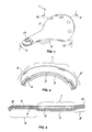
FIG. 1 is an axonometric view of a seating structure of the invention; -
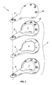
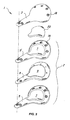
FIG. 2 is an exploded view of the structure ofFIG. 1 ; -
FIG. 3 is an exploded view of the structure ofFIG. 1 according to an alternative embodiment; -
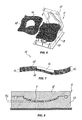
FIG. 4 is a sectional view of the structure ofFig. 1 , as taken along a plane IV-IV; -
FIG. 5 is a sectional view of the structure ofFig. 1 , as taken along a plane V-V; -
FIG. 6 is an axonometric view of a step of the process for making thebase element 5 of the seating structure of the invention; -
FIG. 7 is a sectional view of a few details ofFIG. 6 ; -
FIG. 8 is a sectional view of a mold as taken during another step of the process for making thebase element 5 of the seating structure of the invention. - Referring to the above figures, the seating structure of the invention, generally designated by numeral 1, is embodied herein by a bicycle saddle having an elongate front portion and a widened rear portion for supporting a user. Nonetheless, it will be understood that the seating structure 1 may be configured as a seat, a seating surface of a chair or any other human body support.
- The structure 1 is essentially comprised of a load-bearing
shell 2 and acover element 3 thereon, for contact with a user. The seat 1 may further compriserails 4 or the like for connection to a bicycle frame, not shown but well known per se. - According to the invention, the
shell 2 comprises at least onefirst base element 5 made from a composite material composed of a thermoplastic or thermosetting synthetic polymeric matrix and a reinforcement containing natural fibers, such as wool, cotton, linen, jute fibers. - Thanks to this particular arrangement, the seating structure of the invention has a lower environmental impact as compared to prior art saddles. Indeed, the natural fiber-containing composite material is much more easily recyclable than traditional composite materials.
- Furthermore, many users find the natural fiber-containing composite material comfortable and pleasant to the touch.
- Unless otherwise stated, the technical characteristics of the
base element 5 as mentioned below shall be generally intended to designate from time to time one or more of thebase elements 5, 5', ... of theshell 2. - Also, the natural fibers may be of the woven and/or nonwoven type and may be combined with polymeric and/or synthetic and/or metal fibers for reinforcing the
base element 5. For this purpose, the composite material of the latter may be also filled with nanoparticles, that can be of metal and/or mineral and/or polymeric types. - In a preferred configuration, the synthetic polymeric matrix of the composite material that forms the
base element 5 is of thermoplastic type, preferably in fiber form at ambient temperature. Such fibers may be selected, for example, from the group comprising: polypropylene, polyamide, polybutadiene terephthalate, polyethylene, polystyrene. Nevertheless, it shall be understood that the polymeric matrix may be provided in other states, e.g. in granules, without departure from the inventive scope as defined in the annexed claims. - Advantageously, the
shell 2 includes at least one substantially sheet-like stiffening element, preferably made of metal, laid on thebase element 5 to improve the mechanical properties of theshell 2. - Nevertheless, it shall be understood that the
shell 2 of the saddle 1 may also consist of thefirst base element 5 only, without departure from the inventive scope as defined in the annexed claims. It shall be further understood that thestiffening element 6 may be formed of any material, such as a traditional composite, i.e. carbon fiber, glass, Kevlar® or the like, without departure from the inventive scope as defined in the annexed claims. - Suitably, the
base element 5 may include at least one differential deformable portion, generally designated bynumeral 7. This will make the saddle comfortable and practical even for the most demanding users. As particularly shown inFigures 4 and 5 , the saddle will have stiffer areas, designated bynumerals 8, 8', which will contribute to the increase of its mechanical strength, and more resilient areas, defined by the differentialdeformable portions 7, for improved user comfort. - As used herein, the term "differential deformable portion" or the like shall be meant to indicate an area within the surface of the seat 1 that, under a load, has a considerably lower deformability than at least another area within the same surface under the same load.
- Preferably, the differential
deformable portion 7 may be located in the ischial and/or prostatic and/or peripheral zones of the saddle, thereby defining high user comfort areas in the regions of the body that are more susceptible to injury and pain during exercise. Particularly, one or more differentialdeformable portions 7 may be provided at the contact points between the seat 1 and the inner thigh of a user. - Advantageously, the
stiffening element 6 may have at least one aperture 9 coincident with the moredeformable portions 7, to allow contact of the user with the more comfortable areas. - For further improvement of user comfort, at least one insert 20 of a viscoelastic material or the like, preferably a polyurethane elastomer and/or gel, may be interposed between the
cover element 3 and theshell 2, as shown inFigure 3 and attached thereto. - The
base element 5 may be formed by thermoforming at least onesheet element 10 from the composite material consisting of the synthetic polymeric matrix and the natural fiber-containing reinforcement in a specially designed mold 11. As a non limiting example, asheet element 10 may be used that is formed of jute fibers dispersed in a polypropylene fiber matrix. - In a preferred embodiment, the
sheet element 10 may be laid in the mold 11, compressed between the male andfemale parts - During the thermoforming step, the
sheet element 10 changes from its initial height H1 to a final height H2 defined by the distance between the male andfemale parts sheet element 10 so that, as the H1/H2 compression ratio increases thebase element 5 will have an increasing stiffness. - The differential
deformable portions 7 of thebase element 5 may be obtained by differential compression of thebase element 5 between the male andfemale parts - For example, as shown in
Figures 6 to 8 , at least one layer 10' may be laid on thesheet element 10, preferably made of the same composite material as thesheet element 10, and having at least one aperture coincident with the area designed to define the moredeformable portion 7. - Thus, the assembly formed by the
sheet element 10 and the layer 10', generally designated bynumeral 15, will have differential initial heights, which are designated by H1 at the aperture 14 (defined by the height of thesheet element 10 only) and by H1' at the areas at the periphery of theaperture 14. As particularly shown inFigure 7 , the height H1' is greater than the height H1. - Once the
base element 5 has been formed in the mold 11, in which the male andfemale parts aperture 14, corresponding to the differentialdeformable portion 7, in which the compression ratio is H1/H2 and areas at the periphery of theaperture 14, corresponding to thestiffer areas 8, 8', in which the compression ratio is H1'/H2. -
Figure 2 shows a preferred, non exclusive embodiment of the seating structure of the invention, in which theshell 2 has first andsecond base elements 5, 5' of a composite material composed of the synthetic polymeric matrix and the natural fiber-containing reinforcement as described above, with themetal stiffening element 6 interposed therebetween. The second upper base element 5' has acover element 3 attached thereto, which is preferably made of leather, skin or the like. For this purpose, the latter has aperipheral edge 16 which defines an abutment for thecover element 3, as particularly shown inFigure 5 . -
Figure 3 shows another preferred, non exclusive embodiment of the invention, which is similar to the former except that aviscoelastic insert 20 is coincident with the differentialdeformed portion 7. The insert may be attached to thebase element 5 in a known manner. - In both embodiments additional means may be provided for attachment of the
cover element 3 to theshell 2 and/or of the various layers of theshell 2 to each other, such as nuts or rivets 17 to be introduced in respective throughholes 18. - The seating structure as shown in
Figures 2 and3 may be fabricated using a process that includes the following steps. - First, the first and
second base elements 5, 5' shall undergo preventive thermoforming, by following the steps as shown inFigures 6 to 8 . It shall be understood that at least onesheet element 10 has to be thermoformed for eachbase element 5, 5'. - Advantageously, a composite material including a thermoplastic matrix will be used, for reasons that will appear more clearly hereinbelow.
- Preferably, the pre-thermoforming steps on the first and
second base elements 5, 5' will be carried out at a temperature slightly below the softening point of the thermoplastic matrix of the composite material that forms thesheet elements 10, so that it can be formed with a shape that allows further shaping and handling of thelayers 5, 5', without being the final shape. - After such pre-thermoforming step, the first and
second base elements 5, 5' and thestiffening element 6 interposed therebetween and possibly theinsert 20 are laid in the mold in the order as shown from top to bottom inFigures 2 and3 . Thecover element 3 may be attached to the upper base element 5' directly in the same mold or after this step. - For instance, in the embodiment as shown in
Figure 2 , thecover element 3 may be glued to theshell 2 after thermoforming thereof. On the other hand, in the embodiment ofFigure 3 , thecover element 3 may be first introduced in the mold, followed by the viscoelastic material that is designed to form theinsert 20 and then, in the following order, by the second base element 5', thestiffening element 6 and thefirst base element 5. - Now, in any case, the mold 11 is heated to a temperature near or above the melting temperature of the thermoplastic fibers of the composite material, for the
stiffening element 6 to be safely embedded between the first andsecond base elements 5, 5'. Furthermore, during this step, the thermoplastic matrix of the composite material that forms these elements melts and forms a substantially continuous structure at the points in which the first andsecond base elements 5, 5' are not separated by thestiffening element 6, as shown inFigures 4 and 5 . - The provision of a
stiffening element 6 embedded between the first andsecond base elements 5, 5' imparts excellent mechanical properties to theshell 2. - The above disclosure clearly shows that the seating structure of the invention fulfills the intended purposes and particularly meets the requirement of providing a seating structure that has a relatively low environmental impact.
- The structure and process of the invention are susceptible to a number of changes and variants, within the inventive concept disclosed in the annexed claims. All the details thereof may be replaced by other technically equivalent parts, and the materials may vary depending on different needs, without departure from the scope of the invention.
- While the structure has been described with particular reference to the accompanying figures, the numerals referred to in the disclosure and claims are only used for the sake of a better intelligibility of the invention and shall not be intended to limit the claimed scope in any manner.
Claims (13)
- A seating structure, particularly a bicycle saddle, comprising a load-bearing shell (2) and a cover element (3) designed to contact a user, said shell (2) comprising at least one first base element (5) made from a composite material composed of a polymeric matrix and a fiber-containing reinforcement, wherein said polymeric matrix is synthetic and said fibers of said reinforcement are natural fibers, wherein said shell (2) comprises at least one substantially sheet-like stiffening element (6) attached to said at least one first base element (5), said at least one stiffening element (6) being in direct contact with said at least one first base element (5), characterized in that said seating structure comprises at least one second base element (5'), said at least one stiffening element (6) having a peripheral edge substantially recessed relative to said at least one first and at least one second base elements (5, 5') and being evenly embedded therebetween.
- Seating structure as claimed in claim 1, characterized in that said synthetic polymeric material is of thermoplastic type and in that said synthetic thermoplastic polymeric material is in fiber form at ambient temperature.
- Seating structure as claimed in claim 2, characterized in that said synthetic thermoplastic polymeric fibers are selected in the group comprising: polypropylene, polyamide, polybutadiene terephthalate, polystyrene, polyethylene.
- Seating structure as claimed in claim 1, characterized in that said natural fibers are selected in the group comprising wool, cotton, linen, jute.
- Seating structure as claimed in one or more of claims 1 to 4, characterized in that said composite material is filled with nanoparticles.
- Seating structure as claimed in one or more of claims 1 to 5, characterized in that said at least one base element (5) includes at least one differential deformable portion (7) located in the ischial and/or prostatic and/or peripheral zones of the seat.
- Seating structure as claimed in claim 6, when dependent on claim 1, characterized in that said at least one reinforcement sheet element (6) has a plan shape similar to that of said at least one first base element (5) and has at least one aperture (9) coincident with said at least one differential deformable portion (7).
- Seating structure as claimed in one or more of claims 1 to 7, characterized in that it comprises at least one insert (20) made of a material with a viscoelastic behavior, laid on said at least one first base element (5).
- Seating structure as claimed in claim 8, characterized in that said viscoelastic material of said at least one insert (20) is a polyurethane gel.
- Seating structure as claimed in claim 8, when dependent on claim 6, characterized in that said insert made of a viscoelastic material (20) is located coincident with said at least one differential deformable portion (7).
- A process for making a seating structure as claimed in one or more of claims 1 to 10, wherein said structure comprises a load-bearing shell (2) and a cover element (3) for contact with a user, and wherein said shell (2) comprises at least one base element (5) made from a composite material, at least one stiffening element (6) and a second base element (5') made from a composite material, wherein said at least one base element (5) is obtained by thermoforming a polymeric matrix with reinforcement fibers embedded therein in a mold, characterized in that said polymeric matrix is selected from synthetic polymeric matrices and said reinforcement fibers are selected from natural reinforcement fibers and in that said at least one first base element (5) is obtained by thermoforming, in said mold, at least one sheet element (10) formed of said synthetic polymeric matrix with said natural fibers embedded therein, wherein said process also provides thermoforming of a first and a second base elements (5, 5') mutually coupled with at least one stiffening element (6) interposed therebetween.
- Process as claimed in claim 11, characterized in that said thermoforming is carried out by laying said at least one first sheet element (10) in said element and heating it to a temperature near the melting temperature of said synthetic polymeric matrix.
- Process as claimed in claim 12, characterized in that said at least one base element (5) is obtained by providing an assembly (15) formed of at least one first sheet element (10) and at least one second sheet element (10') substantially similar to the former and having at least one aperture (14) coincident with the ischial, prostatic or peripheral zone of the seat and by compressing said assembly (15) in said mold to impart substantially uniform thickness thereto, with at least one differential deformable portion (7) at said at least one aperture (14).
Applications Claiming Priority (2)
| Application Number | Priority Date | Filing Date | Title |
|---|---|---|---|
| IT000042A ITVI20070042A1 (en) | 2007-02-16 | 2007-02-16 | SEATING STRUCTURE IN NATURAL COMPOSITE MATERIAL, AS WELL AS THE METHOD OF REALIZING THE SAME. |
| PCT/IB2008/050539 WO2008099364A1 (en) | 2007-02-16 | 2008-02-14 | Seating structure made of natural composite material and process for making same |
Publications (2)
| Publication Number | Publication Date |
|---|---|
| EP2139751A1 EP2139751A1 (en) | 2010-01-06 |
| EP2139751B1 true EP2139751B1 (en) | 2011-10-12 |
Family
ID=39580037
Family Applications (1)
| Application Number | Title | Priority Date | Filing Date |
|---|---|---|---|
| EP08710037A Active EP2139751B1 (en) | 2007-02-16 | 2008-02-14 | Seating structure made of natural composite material and process for making same |
Country Status (9)
| Country | Link |
|---|---|
| US (1) | US8308234B2 (en) |
| EP (1) | EP2139751B1 (en) |
| JP (1) | JP2010519104A (en) |
| CN (1) | CN101641252A (en) |
| AT (1) | ATE528199T1 (en) |
| DK (1) | DK2139751T3 (en) |
| IT (1) | ITVI20070042A1 (en) |
| TW (1) | TWI443039B (en) |
| WO (1) | WO2008099364A1 (en) |
Families Citing this family (23)
| Publication number | Priority date | Publication date | Assignee | Title |
|---|---|---|---|---|
| IT1400939B1 (en) | 2010-05-13 | 2013-07-02 | Selle Royal Spa | IMPROVED SEAT SUPPORT |
| CN102371697B (en) * | 2010-08-12 | 2014-07-02 | 米玛国际控股有限公司 | Manufacture method for baby seat |
| ES2565101T3 (en) * | 2010-09-16 | 2016-03-31 | Luca Cassani | Method for manufacturing saddles and the like |
| ITVR20110160A1 (en) * | 2011-07-28 | 2013-01-29 | Selle Royal Spa | SUPPORT FOR HUMAN AND SIMILAR BODY PARTS |
| DE102011052297B4 (en) * | 2011-07-29 | 2018-02-15 | Ulrich Schmid | Saddle for a two-wheeled vehicle |
| US10165862B2 (en) * | 2011-10-31 | 2019-01-01 | Johann Burkhard Schmitz | Support structure for saddle-form seat surface |
| DE102011057020B4 (en) * | 2011-12-23 | 2013-07-04 | Louis Chuang | bicycle saddle |
| CH706685A2 (en) | 2012-06-27 | 2013-12-31 | Ergoview Ag | improved support structure for the human body. |
| USD718543S1 (en) * | 2013-04-24 | 2014-12-02 | Brooks England Ltd. | Saddle |
| ITVR20130143A1 (en) * | 2013-06-17 | 2014-12-18 | Brooks England Ltd | SITTING FOR BICYCLE AND SIMILAR SADDLES, AND PROCEDURE FOR ITS MANUFACTURING. |
| JP2015164833A (en) * | 2014-02-05 | 2015-09-17 | 株式会社マルイ | Bicycle saddle and manufacturing method thereof |
| CN104816769A (en) * | 2014-02-05 | 2015-08-05 | 株式会社丸井 | Saddle for bicycle and manufacturing method thereof |
| TWI565617B (en) | 2015-08-03 | 2017-01-11 | Bicycle seat cushion body with auxiliary function sheet and manufacturing method thereof | |
| IT201700077584A1 (en) * | 2017-07-10 | 2019-01-10 | Selle Royal Spa | MOLD FOR AN ELEMENT OF SUPPORT FOR THE HUMAN BODY, AS A SADDLE |
| US12365410B2 (en) | 2017-09-18 | 2025-07-22 | Reform Technologies Inc. | Moldable bicycle saddles, external saddle heaters, fitting procedures, and related technologies |
| US11173974B2 (en) | 2017-09-18 | 2021-11-16 | Versal Manufacturing, Inc. | Moldable bicycle saddles, external saddle heaters, fitting procedures, and related technologies |
| WO2019058183A2 (en) | 2017-09-18 | 2019-03-28 | Versal Manufacturing, Inc. | Moldable bicycle saddles, fitting procedures, and related technologies |
| WO2022084986A1 (en) * | 2020-10-19 | 2022-04-28 | Tetro Ltd. | Hybrid structure having suspension quality |
| US11472504B2 (en) | 2020-11-13 | 2022-10-18 | David Niles | Bicycle saddles with an ischial-perineal suspension region |
| TWI789905B (en) * | 2021-09-13 | 2023-01-11 | 許秀政 | Composite bicycle seat cushion |
| FR3135441B1 (en) | 2022-05-10 | 2024-04-12 | Berthoud Cycles | Linen-based seat for cycling saddle |
| IT202300008919A1 (en) | 2023-05-05 | 2024-11-05 | Selle Royal Group Spa | Support element for the human body comprising a recycled material and method for its production |
| IT202300012519A1 (en) * | 2023-06-19 | 2024-12-19 | Selle Royal Group S P A | TOP OR SEAT ASSEMBLY FOR A VEHICLE SADDLE. |
Family Cites Families (18)
| Publication number | Priority date | Publication date | Assignee | Title |
|---|---|---|---|---|
| US4098537A (en) * | 1977-03-07 | 1978-07-04 | The Jacobs Corporation | Bicycle saddle |
| JPS61222880A (en) * | 1985-11-09 | 1986-10-03 | 東京シ−ト株式会社 | Frame for saddle type seat for two-wheel barrow through thermoplastic synthetic-resin blow molding |
| US5356205A (en) * | 1992-09-18 | 1994-10-18 | Inmotion, Inc. | Seat assembly with a defined flexure region, venting or support nodules |
| US5766704A (en) * | 1995-10-27 | 1998-06-16 | Acushnet Company | Conforming shoe construction and gel compositions therefor |
| US6756412B2 (en) | 1996-04-25 | 2004-06-29 | Georgia Composites, Inc. | Fiber-reinforced recycled thermoplastic composite and method |
| WO1998055352A2 (en) * | 1997-06-06 | 1998-12-10 | Williams Gilbert J | Ultra lightweight closed cell foam bicycle saddle |
| IT1294713B1 (en) * | 1997-09-19 | 1999-04-12 | Selle Royal Spa | STRUCTURE OF INTEGRAL ELASTIC SUPPORT WITH ORNAMENTAL ELEMENTS, AS WELL AS METHOD OF REALIZATION OF THIS STRUCTURE. |
| DE19806703A1 (en) * | 1998-02-18 | 1999-11-04 | Marx Gmbh J J | Forming layered, nonwoven-composite mat for subsequent hot molding |
| IT1317436B1 (en) * | 2000-04-28 | 2003-07-09 | Selle Italia Srl | SELLA STRUCTURE, PARTICULARLY DESIGNED FOR CYCLES |
| US6409865B1 (en) * | 2000-05-01 | 2002-06-25 | Paul M. Yates | Bicycle saddle production method |
| IT1315498B1 (en) | 2000-08-04 | 2003-02-18 | Selle Royal Spa | SADDLE IN COMPOSITE MATERIAL, IN PARTICULAR FOR BICYCLE AND METHOD FOR ITS REALIZATION |
| TWI233903B (en) | 2003-12-05 | 2005-06-11 | Selle Tech Ind Co Ltd | Shell for bicycle saddle |
| WO2005105558A1 (en) * | 2004-04-26 | 2005-11-10 | Tom Milton | Bicycle saddle |
| US6957857B1 (en) * | 2004-09-20 | 2005-10-25 | Ching-Song Lee | Shell construction for a bicycle seat |
| ITVI20040254A1 (en) | 2004-10-26 | 2005-01-26 | Selle Royal Spa | STRUCTURE OF SADDLE WITH A MEMORY OF SHAPE, PARTICULARLY FOR PEDAL VEHICLES, AS WELL AS THE METHOD OF REALIZING THIS STRUCTURE |
| ITVI20050025A1 (en) * | 2005-01-28 | 2006-07-29 | Selle Royal Spa | ERGONOMIC SUPPORT STRUCTURE IN COMPOSITE MATERIAL, PARTICULARLY FOR SUPPORTING PARTS OF THE HUMAN BODY, AS WELL AS THE METHOD OF REALIZING THE SAME |
| ITVI20050040A1 (en) | 2005-02-10 | 2006-08-11 | Selle Royal Spa | ERGONOMIC SUPPORT STRUCTURE, PARTICULARLY FOR SUPPORTING PARTS OF THE HUMAN BODY, AS WELL AS THE METHOD OF REALIZING THE SAME |
| US7547064B2 (en) * | 2006-05-23 | 2009-06-16 | Louis Garneau Sports Inc. | Ventilated saddle for sporting equipment |
-
2007
- 2007-02-16 IT IT000042A patent/ITVI20070042A1/en unknown
-
2008
- 2008-02-14 US US12/527,229 patent/US8308234B2/en active Active
- 2008-02-14 AT AT08710037T patent/ATE528199T1/en not_active IP Right Cessation
- 2008-02-14 JP JP2009549882A patent/JP2010519104A/en active Pending
- 2008-02-14 CN CN200880009162A patent/CN101641252A/en active Pending
- 2008-02-14 WO PCT/IB2008/050539 patent/WO2008099364A1/en not_active Ceased
- 2008-02-14 EP EP08710037A patent/EP2139751B1/en active Active
- 2008-02-14 DK DK08710037.6T patent/DK2139751T3/en active
- 2008-02-15 TW TW097105283A patent/TWI443039B/en active
Also Published As
| Publication number | Publication date |
|---|---|
| TWI443039B (en) | 2014-07-01 |
| DK2139751T3 (en) | 2012-02-06 |
| JP2010519104A (en) | 2010-06-03 |
| ITVI20070042A1 (en) | 2008-08-17 |
| CN101641252A (en) | 2010-02-03 |
| WO2008099364A1 (en) | 2008-08-21 |
| US8308234B2 (en) | 2012-11-13 |
| US20100013278A1 (en) | 2010-01-21 |
| TW200911602A (en) | 2009-03-16 |
| EP2139751A1 (en) | 2010-01-06 |
| ATE528199T1 (en) | 2011-10-15 |
Similar Documents
| Publication | Publication Date | Title |
|---|---|---|
| EP2139751B1 (en) | Seating structure made of natural composite material and process for making same | |
| US8128164B2 (en) | Human body supporting structure, particularly bicycle saddle and method of making same | |
| US6409269B1 (en) | Vehicle seat assembly with thermoformed fibrous suspension panel | |
| EP2144804B1 (en) | Seating structure and method of making same | |
| US8512842B2 (en) | Composite material human body support and process for making same | |
| US20140159445A1 (en) | Support for human body parts | |
| JP2018525279A (en) | Bicycle seat and method for manufacturing bicycle saddle | |
| WO1999043229A1 (en) | Thermoformable fabric shoe sole and upper | |
| EP2170688B1 (en) | Elastic human body support and method of making same | |
| US20190061853A1 (en) | Bicycle Saddle | |
| US8002345B2 (en) | Ultra light saddle structure, particularly for pedal-driven vehicles and process for making its support frame | |
| EP1846282B1 (en) | Ergonomic support structure made of composite material for human body parts and method of manufacturing it | |
| US8746791B2 (en) | Shape-memory saddle structure, particularly for pedal driven vehicles, and process for making such structure | |
| US11584468B2 (en) | Bicycle saddle | |
| JPH0518965Y2 (en) | ||
| TWI501894B (en) | Bicycle saddle | |
| KR20060079843A (en) | Cushioning material and cushioning material made of spring-structured resin molded article and mold used in the manufacturing method |
Legal Events
| Date | Code | Title | Description |
|---|---|---|---|
| PUAI | Public reference made under article 153(3) epc to a published international application that has entered the european phase |
Free format text: ORIGINAL CODE: 0009012 |
|
| 17P | Request for examination filed |
Effective date: 20090915 |
|
| AK | Designated contracting states |
Kind code of ref document: A1 Designated state(s): AT BE BG CH CY CZ DE DK EE ES FI FR GB GR HR HU IE IS IT LI LT LU LV MC MT NL NO PL PT RO SE SI SK TR |
|
| DAX | Request for extension of the european patent (deleted) | ||
| 17Q | First examination report despatched |
Effective date: 20100429 |
|
| RAP1 | Party data changed (applicant data changed or rights of an application transferred) |
Owner name: BROOKS ENGLAND LIMITED |
|
| GRAP | Despatch of communication of intention to grant a patent |
Free format text: ORIGINAL CODE: EPIDOSNIGR1 |
|
| GRAS | Grant fee paid |
Free format text: ORIGINAL CODE: EPIDOSNIGR3 |
|
| GRAA | (expected) grant |
Free format text: ORIGINAL CODE: 0009210 |
|
| AK | Designated contracting states |
Kind code of ref document: B1 Designated state(s): AT BE BG CH CY CZ DE DK EE ES FI FR GB GR HR HU IE IS IT LI LT LU LV MC MT NL NO PL PT RO SE SI SK TR |
|
| REG | Reference to a national code |
Ref country code: GB Ref legal event code: FG4D |
|
| REG | Reference to a national code |
Ref country code: CH Ref legal event code: EP |
|
| REG | Reference to a national code |
Ref country code: IE Ref legal event code: FG4D |
|
| REG | Reference to a national code |
Ref country code: DE Ref legal event code: R096 Ref document number: 602008010390 Country of ref document: DE Effective date: 20111215 |
|
| REG | Reference to a national code |
Ref country code: NL Ref legal event code: T3 |
|
| REG | Reference to a national code |
Ref country code: DK Ref legal event code: T3 |
|
| REG | Reference to a national code |
Ref country code: CH Ref legal event code: NV Representative=s name: ISLER & PEDRAZZINI AG |
|
| LTIE | Lt: invalidation of european patent or patent extension |
Effective date: 20111012 |
|
| REG | Reference to a national code |
Ref country code: AT Ref legal event code: MK05 Ref document number: 528199 Country of ref document: AT Kind code of ref document: T Effective date: 20111012 |
|
| PG25 | Lapsed in a contracting state [announced via postgrant information from national office to epo] |
Ref country code: LT Free format text: LAPSE BECAUSE OF FAILURE TO SUBMIT A TRANSLATION OF THE DESCRIPTION OR TO PAY THE FEE WITHIN THE PRESCRIBED TIME-LIMIT Effective date: 20111012 Ref country code: NO Free format text: LAPSE BECAUSE OF FAILURE TO SUBMIT A TRANSLATION OF THE DESCRIPTION OR TO PAY THE FEE WITHIN THE PRESCRIBED TIME-LIMIT Effective date: 20120112 Ref country code: BE Free format text: LAPSE BECAUSE OF FAILURE TO SUBMIT A TRANSLATION OF THE DESCRIPTION OR TO PAY THE FEE WITHIN THE PRESCRIBED TIME-LIMIT Effective date: 20111012 Ref country code: IS Free format text: LAPSE BECAUSE OF FAILURE TO SUBMIT A TRANSLATION OF THE DESCRIPTION OR TO PAY THE FEE WITHIN THE PRESCRIBED TIME-LIMIT Effective date: 20120212 |
|
| PG25 | Lapsed in a contracting state [announced via postgrant information from national office to epo] |
Ref country code: HR Free format text: LAPSE BECAUSE OF FAILURE TO SUBMIT A TRANSLATION OF THE DESCRIPTION OR TO PAY THE FEE WITHIN THE PRESCRIBED TIME-LIMIT Effective date: 20111012 Ref country code: SE Free format text: LAPSE BECAUSE OF FAILURE TO SUBMIT A TRANSLATION OF THE DESCRIPTION OR TO PAY THE FEE WITHIN THE PRESCRIBED TIME-LIMIT Effective date: 20111012 Ref country code: SI Free format text: LAPSE BECAUSE OF FAILURE TO SUBMIT A TRANSLATION OF THE DESCRIPTION OR TO PAY THE FEE WITHIN THE PRESCRIBED TIME-LIMIT Effective date: 20111012 Ref country code: PT Free format text: LAPSE BECAUSE OF FAILURE TO SUBMIT A TRANSLATION OF THE DESCRIPTION OR TO PAY THE FEE WITHIN THE PRESCRIBED TIME-LIMIT Effective date: 20120213 Ref country code: LV Free format text: LAPSE BECAUSE OF FAILURE TO SUBMIT A TRANSLATION OF THE DESCRIPTION OR TO PAY THE FEE WITHIN THE PRESCRIBED TIME-LIMIT Effective date: 20111012 Ref country code: GR Free format text: LAPSE BECAUSE OF FAILURE TO SUBMIT A TRANSLATION OF THE DESCRIPTION OR TO PAY THE FEE WITHIN THE PRESCRIBED TIME-LIMIT Effective date: 20120113 |
|
| PG25 | Lapsed in a contracting state [announced via postgrant information from national office to epo] |
Ref country code: CY Free format text: LAPSE BECAUSE OF FAILURE TO SUBMIT A TRANSLATION OF THE DESCRIPTION OR TO PAY THE FEE WITHIN THE PRESCRIBED TIME-LIMIT Effective date: 20111012 |
|
| PG25 | Lapsed in a contracting state [announced via postgrant information from national office to epo] |
Ref country code: CZ Free format text: LAPSE BECAUSE OF FAILURE TO SUBMIT A TRANSLATION OF THE DESCRIPTION OR TO PAY THE FEE WITHIN THE PRESCRIBED TIME-LIMIT Effective date: 20111012 Ref country code: BG Free format text: LAPSE BECAUSE OF FAILURE TO SUBMIT A TRANSLATION OF THE DESCRIPTION OR TO PAY THE FEE WITHIN THE PRESCRIBED TIME-LIMIT Effective date: 20120112 Ref country code: SK Free format text: LAPSE BECAUSE OF FAILURE TO SUBMIT A TRANSLATION OF THE DESCRIPTION OR TO PAY THE FEE WITHIN THE PRESCRIBED TIME-LIMIT Effective date: 20111012 Ref country code: EE Free format text: LAPSE BECAUSE OF FAILURE TO SUBMIT A TRANSLATION OF THE DESCRIPTION OR TO PAY THE FEE WITHIN THE PRESCRIBED TIME-LIMIT Effective date: 20111012 |
|
| PLBE | No opposition filed within time limit |
Free format text: ORIGINAL CODE: 0009261 |
|
| STAA | Information on the status of an ep patent application or granted ep patent |
Free format text: STATUS: NO OPPOSITION FILED WITHIN TIME LIMIT |
|
| PG25 | Lapsed in a contracting state [announced via postgrant information from national office to epo] |
Ref country code: PL Free format text: LAPSE BECAUSE OF FAILURE TO SUBMIT A TRANSLATION OF THE DESCRIPTION OR TO PAY THE FEE WITHIN THE PRESCRIBED TIME-LIMIT Effective date: 20111012 Ref country code: RO Free format text: LAPSE BECAUSE OF FAILURE TO SUBMIT A TRANSLATION OF THE DESCRIPTION OR TO PAY THE FEE WITHIN THE PRESCRIBED TIME-LIMIT Effective date: 20111012 |
|
| 26N | No opposition filed |
Effective date: 20120713 |
|
| PG25 | Lapsed in a contracting state [announced via postgrant information from national office to epo] |
Ref country code: MC Free format text: LAPSE BECAUSE OF NON-PAYMENT OF DUE FEES Effective date: 20120229 |
|
| REG | Reference to a national code |
Ref country code: DE Ref legal event code: R097 Ref document number: 602008010390 Country of ref document: DE Effective date: 20120713 |
|
| REG | Reference to a national code |
Ref country code: IE Ref legal event code: MM4A |
|
| PG25 | Lapsed in a contracting state [announced via postgrant information from national office to epo] |
Ref country code: IE Free format text: LAPSE BECAUSE OF NON-PAYMENT OF DUE FEES Effective date: 20120214 Ref country code: AT Free format text: LAPSE BECAUSE OF FAILURE TO SUBMIT A TRANSLATION OF THE DESCRIPTION OR TO PAY THE FEE WITHIN THE PRESCRIBED TIME-LIMIT Effective date: 20111012 |
|
| PG25 | Lapsed in a contracting state [announced via postgrant information from national office to epo] |
Ref country code: FI Free format text: LAPSE BECAUSE OF FAILURE TO SUBMIT A TRANSLATION OF THE DESCRIPTION OR TO PAY THE FEE WITHIN THE PRESCRIBED TIME-LIMIT Effective date: 20111012 |
|
| PG25 | Lapsed in a contracting state [announced via postgrant information from national office to epo] |
Ref country code: MT Free format text: LAPSE BECAUSE OF FAILURE TO SUBMIT A TRANSLATION OF THE DESCRIPTION OR TO PAY THE FEE WITHIN THE PRESCRIBED TIME-LIMIT Effective date: 20111012 |
|
| PG25 | Lapsed in a contracting state [announced via postgrant information from national office to epo] |
Ref country code: ES Free format text: LAPSE BECAUSE OF FAILURE TO SUBMIT A TRANSLATION OF THE DESCRIPTION OR TO PAY THE FEE WITHIN THE PRESCRIBED TIME-LIMIT Effective date: 20120123 |
|
| PG25 | Lapsed in a contracting state [announced via postgrant information from national office to epo] |
Ref country code: TR Free format text: LAPSE BECAUSE OF FAILURE TO SUBMIT A TRANSLATION OF THE DESCRIPTION OR TO PAY THE FEE WITHIN THE PRESCRIBED TIME-LIMIT Effective date: 20111012 |
|
| REG | Reference to a national code |
Ref country code: DE Ref legal event code: R082 Ref document number: 602008010390 Country of ref document: DE Representative=s name: TETZNER & PARTNER MBB PATENT- UND RECHTSANWAEL, DE |
|
| PG25 | Lapsed in a contracting state [announced via postgrant information from national office to epo] |
Ref country code: LU Free format text: LAPSE BECAUSE OF NON-PAYMENT OF DUE FEES Effective date: 20120214 |
|
| PG25 | Lapsed in a contracting state [announced via postgrant information from national office to epo] |
Ref country code: HU Free format text: LAPSE BECAUSE OF FAILURE TO SUBMIT A TRANSLATION OF THE DESCRIPTION OR TO PAY THE FEE WITHIN THE PRESCRIBED TIME-LIMIT Effective date: 20080214 |
|
| REG | Reference to a national code |
Ref country code: FR Ref legal event code: PLFP Year of fee payment: 9 |
|
| REG | Reference to a national code |
Ref country code: FR Ref legal event code: PLFP Year of fee payment: 10 |
|
| REG | Reference to a national code |
Ref country code: FR Ref legal event code: PLFP Year of fee payment: 11 |
|
| P01 | Opt-out of the competence of the unified patent court (upc) registered |
Effective date: 20230427 |
|
| REG | Reference to a national code |
Ref country code: CH Ref legal event code: U11 Free format text: ST27 STATUS EVENT CODE: U-0-0-U10-U11 (AS PROVIDED BY THE NATIONAL OFFICE) Effective date: 20260301 |
|
| PGFP | Annual fee paid to national office [announced via postgrant information from national office to epo] |
Ref country code: NL Payment date: 20260226 Year of fee payment: 19 |
|
| PGFP | Annual fee paid to national office [announced via postgrant information from national office to epo] |
Ref country code: GB Payment date: 20260227 Year of fee payment: 19 |
|
| PGFP | Annual fee paid to national office [announced via postgrant information from national office to epo] |
Ref country code: DK Payment date: 20260225 Year of fee payment: 19 Ref country code: DE Payment date: 20260227 Year of fee payment: 19 |
|
| PGFP | Annual fee paid to national office [announced via postgrant information from national office to epo] |
Ref country code: IT Payment date: 20260216 Year of fee payment: 19 |
|
| PGFP | Annual fee paid to national office [announced via postgrant information from national office to epo] |
Ref country code: FR Payment date: 20260225 Year of fee payment: 19 |
|
| PGFP | Annual fee paid to national office [announced via postgrant information from national office to epo] |
Ref country code: CH Payment date: 20260301 Year of fee payment: 19 |