EP2139227A2 - Image-capturing device - Google Patents
Image-capturing device Download PDFInfo
- Publication number
- EP2139227A2 EP2139227A2 EP09173230A EP09173230A EP2139227A2 EP 2139227 A2 EP2139227 A2 EP 2139227A2 EP 09173230 A EP09173230 A EP 09173230A EP 09173230 A EP09173230 A EP 09173230A EP 2139227 A2 EP2139227 A2 EP 2139227A2
- Authority
- EP
- European Patent Office
- Prior art keywords
- image
- external monitor
- electronic viewfinder
- touch panel
- pointer
- Prior art date
- Legal status (The legal status is an assumption and is not a legal conclusion. Google has not performed a legal analysis and makes no representation as to the accuracy of the status listed.)
- Granted
Links
Images


Classifications
-
- H—ELECTRICITY
- H04—ELECTRIC COMMUNICATION TECHNIQUE
- H04N—PICTORIAL COMMUNICATION, e.g. TELEVISION
- H04N23/00—Cameras or camera modules comprising electronic image sensors; Control thereof
- H04N23/60—Control of cameras or camera modules
- H04N23/63—Control of cameras or camera modules by using electronic viewfinders
- H04N23/631—Graphical user interfaces [GUI] specially adapted for controlling image capture or setting capture parameters
- H04N23/632—Graphical user interfaces [GUI] specially adapted for controlling image capture or setting capture parameters for displaying or modifying preview images prior to image capturing, e.g. variety of image resolutions or capturing parameters
-
- H—ELECTRICITY
- H04—ELECTRIC COMMUNICATION TECHNIQUE
- H04N—PICTORIAL COMMUNICATION, e.g. TELEVISION
- H04N23/00—Cameras or camera modules comprising electronic image sensors; Control thereof
- H04N23/50—Constructional details
- H04N23/53—Constructional details of electronic viewfinders, e.g. rotatable or detachable
- H04N23/531—Constructional details of electronic viewfinders, e.g. rotatable or detachable being rotatable or detachable
-
- G—PHYSICS
- G06—COMPUTING OR CALCULATING; COUNTING
- G06F—ELECTRIC DIGITAL DATA PROCESSING
- G06F3/00—Input arrangements for transferring data to be processed into a form capable of being handled by the computer; Output arrangements for transferring data from processing unit to output unit, e.g. interface arrangements
- G06F3/01—Input arrangements or combined input and output arrangements for interaction between user and computer
- G06F3/048—Interaction techniques based on graphical user interfaces [GUI]
- G06F3/0487—Interaction techniques based on graphical user interfaces [GUI] using specific features provided by the input device, e.g. functions controlled by the rotation of a mouse with dual sensing arrangements, or of the nature of the input device, e.g. tap gestures based on pressure sensed by a digitiser
- G06F3/0488—Interaction techniques based on graphical user interfaces [GUI] using specific features provided by the input device, e.g. functions controlled by the rotation of a mouse with dual sensing arrangements, or of the nature of the input device, e.g. tap gestures based on pressure sensed by a digitiser using a touch-screen or digitiser, e.g. input of commands through traced gestures
-
- H—ELECTRICITY
- H04—ELECTRIC COMMUNICATION TECHNIQUE
- H04N—PICTORIAL COMMUNICATION, e.g. TELEVISION
- H04N23/00—Cameras or camera modules comprising electronic image sensors; Control thereof
- H04N23/50—Constructional details
- H04N23/53—Constructional details of electronic viewfinders, e.g. rotatable or detachable
-
- H—ELECTRICITY
- H04—ELECTRIC COMMUNICATION TECHNIQUE
- H04N—PICTORIAL COMMUNICATION, e.g. TELEVISION
- H04N23/00—Cameras or camera modules comprising electronic image sensors; Control thereof
- H04N23/60—Control of cameras or camera modules
- H04N23/65—Control of camera operation in relation to power supply
- H04N23/651—Control of camera operation in relation to power supply for reducing power consumption by affecting camera operations, e.g. sleep mode, hibernation mode or power off of selective parts of the camera
Definitions
- the present invention relates to an image-capturing device having two image display systems which are an electronic viewfinder and an external monitor.
- the image-capturing device simplifies various operations which are associated with the taking of photographs when a photograph is taken using the electronic viewfinder.
- an image-capturing device such as video cameras or still cameras having both an electronic viewfinder (hereinafter abbreviated as an "EVF") and an external monitor
- EMF electronic viewfinder
- an image-capturing device in which transparent switches (commonly called a touch panel), through which it is possible to see an image displayed therebelow, are mounted on the image display screen of an external monitor. Since the touch panel is well known, a description of the operating principles, etc., is omitted.
- an operation area (operation switch) displayed as a two-dimensional image on an image display surface is directly touched by a finger, etc., in order to perform, for example, focus adjustment, brightness adjustment, etc., on a photographic image while taking a photograph.
- an image-capturing device which comprises an external monitor which has a touch panel mounted on an image display screen, the image display screen having a backlight, and which has an openable/closeable and rotatable mechanism; an electronic viewfinder which is smaller than the external monitor and which has an eyepiece section; and a display unit for displaying a pointer which moves within the screen of the electronic viewfinder in accordance with an operation of the touch panel and displays an operation area for inputting an instruction of various operations which are associated with taking a photograph by specifying and selecting the operation area by the pointer.
- the pointer is moved by operating the touch panel in order to select a desired operation area, thereby inputting an instruction of various operations.
- an image-capturing device 1 is a video camera having an electronic viewfinder (EVF) 2 and an external monitor 3 as image display systems for displaying an image of an object or a replayed image when taking a photograph or when replaying the image.
- EVF electronic viewfinder
- LCD liquid-crystal device
- the external monitor 3 is supported on a main unit 4 in such a manner as to be openable/closeable and rotatable with respect to the main unit 4.
- a touch panel 6 for use with, for example, an electrostatic-capacitance detection method, which is transparent so that an image displayed on an image display screen 5 can be seen, is pasted onto the external monitor 3, that is, the image display screen 5 of an LCD panel 3a.
- taking a photograph using the external monitor 3 is performed when the external monitor 3 is opened with respect to the main unit 4, as shown in Fig. 2 , and while viewing an image 8 (see Fig. 7 ) of the object displayed on the external monitor 3.
- the touch panel 6 for sensing, in a two-dimensional manner, the position at which the finger, etc., of the user touches is pasted on the image display screen 5 of the external monitor 3. Therefore, when the user touches an appropriate operation button 9, the position thereof is sensed by the touch panel 6, and this is notified to a system control section of the video camera 1, whereby a corresponding process is performed.
- the various operation buttons 9, 9, ... displayed together with the image of the object on the screen 5 of the external monitor 3 can be operated as if they were actual operation buttons while viewing the state of the image 8 of the object on which the operation is to be performed. Therefore, the video camera 1 has the feature that user interfacing can be performed more interactively than a conventional operation system.
- the external monitor 3 has the drawback that if external light is too bright, such as while taking a photograph outdoors, the image displayed on the screen 5 becomes difficult to see and the lifetime of the battery is shortened because the power consumption of a backlight used in the LCD, etc., is large. In order to avoid these drawbacks, taking a photograph is also performed by using the EVF 2.
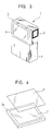
- Taking of photograph using the EVF 2 in the image-capturing device 1 is performed when the external monitor 3 is housed in the main unit 4 with the image display screen 5 facing outward, as shown in Figs. 3 and 5 .
- the image 8 of the object, various operation buttons 9, 9, ..., and a cursor (pointer) 11 in the shape of an arrow are displayed on a screen within the EVF 2 in a manner similar to that for the external monitor 3.
- the cursor 11 is capable of performing a movement and an operation of selecting the various operation buttons 9, 9, ... by operating the touch panel 6 pasted on the image display screen 5 of the external monitor 3 as a pointing device in what is commonly called a GUI (Graphical User Interface) like a track-pad used in a notebook-type personal computer.
- GUI Graphic User Interface
- the cursor 11 is displayed on the screen of the EVF 2, and this cursor 11 is operated by using the touch panel 6 pasted onto the image display screen 5 of the external monitor 3, making it possible to realize nearly the same ease of operation as that when taking a photograph with a combination of the external monitor 3 and the touch panel 6. Therefore, in the image-capturing device, such as a video camera, having an EVF and an external monitor, when the EVF is used, the problem of the ease of operation being reduced when a touch panel is used for an operation can be solved. Moreover, the addition of another operation device used only when the EVF is used is unnecessary. Thus, it is possible to realize similar ease of operation when the EVF is used and when the external monitor is used.
- the image-capturing device of the present invention is an image-capturing device having an electronic viewfinder and an external monitor as two image display systems.
- a touch panel is mounted on the image display screen of the external monitor.
- a pointer which moves within the screen in accordance with an operation of the touch panel, and an operation area for inputting an instruction of various operations which are associated with taking a photograph by specifying and selecting the operation area by the pointer are displayed on the electronic viewfinder. Furthermore, when an image is recorded or replayed by using the electronic viewfinder, the pointer is moved by operating the touch panel in order to select a desired operation area, thereby inputting an instruction of various operations.
- the external monitor when an image is recorded or replayed by using the electronic viewfinder, the external monitor is placed in a power saving mode. Thus, it is possible to extend the operating time when driven by a battery.
Landscapes
- Engineering & Computer Science (AREA)
- Multimedia (AREA)
- Signal Processing (AREA)
- Human Computer Interaction (AREA)
- General Engineering & Computer Science (AREA)
- Theoretical Computer Science (AREA)
- Physics & Mathematics (AREA)
- General Physics & Mathematics (AREA)
- Studio Devices (AREA)
- Viewfinders (AREA)
- Indication In Cameras, And Counting Of Exposures (AREA)
Abstract
Description
- The present invention relates to an image-capturing device having two image display systems which are an electronic viewfinder and an external monitor. The image-capturing device simplifies various operations which are associated with the taking of photographs when a photograph is taken using the electronic viewfinder.
- In image-capturing devices, such as video cameras or still cameras having both an electronic viewfinder (hereinafter abbreviated as an "EVF") and an external monitor, an image-capturing device is known in which transparent switches (commonly called a touch panel), through which it is possible to see an image displayed therebelow, are mounted on the image display screen of an external monitor. Since the touch panel is well known, a description of the operating principles, etc., is omitted.
- In such an image-capturing device using a touch panel as an operation system, an operation area (operation switch) displayed as a two-dimensional image on an image display surface is directly touched by a finger, etc., in order to perform, for example, focus adjustment, brightness adjustment, etc., on a photographic image while taking a photograph.
- However, in an image-capturing device using a touch panel, such as that described above, there is a problem in that the operation when taking a photograph while viewing the external monitor screen is completely different from the operation when taking a photograph while viewing through the EVF.
- When taking a photograph while viewing the external monitor screen, a photographer may perform various adjustments by touching, by a finger, etc., the touch panel on the image of the operation switch which is displayed on the screen at the same time as the photographic image. However, when a photograph is taken while viewing through the EVF, it is impossible to view the EVF and the external monitor screen simultaneously. Therefore, even if an operation switch similar to that displayed on the external monitor screen is displayed on the EVF, it is impossible to perform an operation by touching a specific portion of the touch panel corresponding to the operation switch.
- Therefore, when taking a photograph while viewing through the EVF, an operation must be performed by using a dedicated operation switch, etc., which is mounted separately, requiring a user to perform an operation different from that when taking a photograph while viewing the external monitor screen. This leads to an increased cost of the image-capturing device and a more complex and troublesome user operation.
- In view of the above-described problems, it is an object of the present invention to provide various common operation procedures when an EVF is used and when an external monitor is used in an image-capturing device having two image display systems which are an EVF and an external monitor, and which uses a touch panel as various operation switches while taking a photograph, etc.
- To achieve the above-mentioned object, according to the present invention, there is provided an image-capturing device which comprises an external monitor which has a touch panel mounted on an image display screen, the image display screen having a backlight, and which has an openable/closeable and rotatable mechanism; an electronic viewfinder which is smaller than the external monitor and which has an eyepiece section; and a display unit for displaying a pointer which moves within the screen of the electronic viewfinder in accordance with an operation of the touch panel and displays an operation area for inputting an instruction of various operations which are associated with taking a photograph by specifying and selecting the operation area by the pointer. When an image is recorded or replayed by using the electronic viewfinder, the pointer is moved by operating the touch panel in order to select a desired operation area, thereby inputting an instruction of various operations.
- Therefore, it is possible to provide substantially common methods of various operations when an image is recorded or replayed by using an EVF and when an image is recorded or replayed by using an external monitor.
- In the accompanying drawings, there are shown an illustrative embodiment of the invention from which these and other of its objectives, novel features, and advantages will be readily apparent.
-
-
Fig. 1 is a perspective view showing the entire image-capturing device in a state in which an external monitor is closed. -
Fig. 2 is a perspective view showing the entire image-capturing device in a state in which the external monitor is opened. -
Fig. 3 shows the entire image-capturing device in a state in which the external monitor is closed with the image display screen facing outward. -
Fig. 4 is a perspective view showing an LCD panel and a touch panel of the external monitor. -
Fig. 5 shows a method of moving a pointer by operating the touch panel when taking a photograph by using an EVF. -
Fig. 6 shows a method of selecting an operation button by the pointer by operating the touch panel when taking a photograph by using the EVF. -
Fig. 7 shows the screen of the external monitor when taking a photograph by the external monitor. -
Fig. 8 shows the screen of the EVF when the pointer is moved by operating the touch panel when taking a photograph by using the EVF. -
Fig. 9 shows the screen of the EVF when an operation button is selected by the pointer by operating the touch panel when taking a photograph by using the EVF. - The preferred embodiment of the present invention will be described below with reference to the accompanying drawings.
- As shown in
Figs. 1 and 2 , an image-capturingdevice 1 is a video camera having an electronic viewfinder (EVF) 2 and anexternal monitor 3 as image display systems for displaying an image of an object or a replayed image when taking a photograph or when replaying the image. - Both the EVF 2 and the
external monitor 3, which differ in size, use a liquid-crystal device (LCD), etc., as a display device. - As shown by the arrow in
Fig. 2 , theexternal monitor 3 is supported on amain unit 4 in such a manner as to be openable/closeable and rotatable with respect to themain unit 4. As shown inFig. 4 , atouch panel 6 for use with, for example, an electrostatic-capacitance detection method, which is transparent so that an image displayed on animage display screen 5 can be seen, is pasted onto theexternal monitor 3, that is, theimage display screen 5 of anLCD panel 3a. - In the
video camera 1, taking a photograph using theexternal monitor 3 is performed when theexternal monitor 3 is opened with respect to themain unit 4, as shown inFig. 2 , and while viewing an image 8 (seeFig. 7 ) of the object displayed on theexternal monitor 3. - At this time, various operations which are associated with taking a photograph are performed by the user directly touching, with a finger,
various operation buttons image 8 of the object displayed on thescreen 5 of theexternal monitor 3, for example, as shown inFig. 7 . - More specifically, as described above, the
touch panel 6 for sensing, in a two-dimensional manner, the position at which the finger, etc., of the user touches is pasted on theimage display screen 5 of theexternal monitor 3. Therefore, when the user touches anappropriate operation button 9, the position thereof is sensed by thetouch panel 6, and this is notified to a system control section of thevideo camera 1, whereby a corresponding process is performed. - As described above, in the image-capturing
device 1, when taking a photograph by using theexternal monitor 3, thevarious operation buttons screen 5 of theexternal monitor 3 can be operated as if they were actual operation buttons while viewing the state of theimage 8 of the object on which the operation is to be performed. Therefore, thevideo camera 1 has the feature that user interfacing can be performed more interactively than a conventional operation system. - The
external monitor 3 has the drawback that if external light is too bright, such as while taking a photograph outdoors, the image displayed on thescreen 5 becomes difficult to see and the lifetime of the battery is shortened because the power consumption of a backlight used in the LCD, etc., is large. In order to avoid these drawbacks, taking a photograph is also performed by using the EVF 2. - Taking of photograph using the
EVF 2 in the image-capturingdevice 1 is performed when theexternal monitor 3 is housed in themain unit 4 with theimage display screen 5 facing outward, as shown inFigs. 3 and5 . - As shown in
Figs. 8 and9 , theimage 8 of the object,various operation buttons EVF 2 in a manner similar to that for theexternal monitor 3. - The
cursor 11 is capable of performing a movement and an operation of selecting thevarious operation buttons touch panel 6 pasted on theimage display screen 5 of theexternal monitor 3 as a pointing device in what is commonly called a GUI (Graphical User Interface) like a track-pad used in a notebook-type personal computer. - More specifically, as shown in
Figs. 5 and8 , when the finger is moved in any desired direction while touching thetouch panel 6, thecursor 11 is moved within the screen in a manner similar to the movement traced by the finger on thetouch panel 6. - Also, in the operation of selecting the
operation buttons Figs. 6 and9 , by moving thecursor 11 onto a desiredoperation button 9 and by tapping (hitting thetouch panel 6 and releasing) a finger on thetouch panel 6 at that position, this is notified to the system control section of thevideo camera 1 as if an actual switch was pressed, and a corresponding process is performed. - At this time, there is no need to display the
image 8 of the object and thevarious operation buttons external monitor 3 nor to switch on the backlight. Therefore, in thevideo camera 1, in order to reduce power consumption and to increase the battery-driven operating time when taking a photograph or replaying by the EVF 2, a power saving mode for cutting the power supply to the backlight, which has a high power consumption, is set. As a result of cutting all the signals and power supply to the external monitor 3 (LCD), more power is saved, thereby obtaining a desirable power saving mode. - As described above, in the
video camera 1, when taking a photograph by the EVF 2 when theexternal monitor 3 is closed, thecursor 11 is displayed on the screen of the EVF 2, and thiscursor 11 is operated by using thetouch panel 6 pasted onto theimage display screen 5 of theexternal monitor 3, making it possible to realize nearly the same ease of operation as that when taking a photograph with a combination of theexternal monitor 3 and thetouch panel 6. Therefore, in the image-capturing device, such as a video camera, having an EVF and an external monitor, when the EVF is used, the problem of the ease of operation being reduced when a touch panel is used for an operation can be solved. Moreover, the addition of another operation device used only when the EVF is used is unnecessary. Thus, it is possible to realize similar ease of operation when the EVF is used and when the external monitor is used. - Although in the above-described embodiment an example is described in which the present invention is applied to a video camera, it is possible to apply the present invention to an electronic still camera having an EVF and an external monitor.
- Furthermore, the specific shape and construction of each section shown in the above-described embodiment are only examples exemplifying the present invention, and the technological scope of the present invention should not be limited by these examples.
- As is clear from the foregoing, the image-capturing device of the present invention is an image-capturing device having an electronic viewfinder and an external monitor as two image display systems. A touch panel is mounted on the image display screen of the external monitor. A pointer which moves within the screen in accordance with an operation of the touch panel, and an operation area for inputting an instruction of various operations which are associated with taking a photograph by specifying and selecting the operation area by the pointer are displayed on the electronic viewfinder. Furthermore, when an image is recorded or replayed by using the electronic viewfinder, the pointer is moved by operating the touch panel in order to select a desired operation area, thereby inputting an instruction of various operations. This makes it possible to provide substantially common methods of various operations when an image is recorded or replayed by using an EVF and when an image is recorded or replayed by using an external monitor. As a result, it is possible to prevent an increased cost of the device as a result of providing a dedicated operation system when the electronic viewfinder is used, and because the user does not need to memorize the operations of two systems, operations can be simplified.
- Also, in the image-capturing device of the present invention, when an image is recorded or replayed by using the electronic viewfinder, the external monitor is placed in a power saving mode. Thus, it is possible to extend the operating time when driven by a battery.
- Many different embodiments of the present invention may be constructed without departing from the scope of the present invention. It should be understood that the present invention is not limited to the specific embodiment described in this specification. To the contrary, the present invention is intended to cover various modifications and equivalent arrangements included within the scope of the invention as hereafter claimed. The scope of the following claims is to be accorded the broadest interpretation so as to encompass all such modifications, equivalent structures and functions.
Claims (5)
- An image-capturing device (1) comprising:an external monitor (3) which has a touch panel (6) mounted on an image display screen (5), said image display screen (5) having a backlight, and which has an openable/closeable and rotatable mechanism;an electronic viewfinder (2); characterized by further includingdisplay means for displaying a pointer (11) which moves within a screen of said electronic viewfinder (2) and for displaying within a screen (5) of said electronic viewfinder (2) in a manner similar to that for the external monitor (3) an operation area for inputting an instruction of various operations which are associated with taking a photograph by specifying and selecting a specific portion of the operation area by the pointer (11), wherein said pointer moves within the screen of said electronic viewfinder in accordance with an operation of said touch panel (6), so that, when an image is recorded or replayed by using said electronic viewfinder (2), the pointer (11) is moved by operating the touch panel (6) in order to select a desired portion of the operation area, thereby inputting an instruction of various operations and enabling said electronic viewfinder (2) and said external monitor (3) to perform common methods of various operations associated with recording and replaying an image.
- An image-capturing device according to claim 1, wherein, when an operation of inputting an instruction of various operations is performed by using said electronic viewfinder (2), the image display screen (5) of said external monitor (3) is housed in a main unit (4) of the device with the image display screen (5) of said external monitor (3) facing the outside of the device main unit (4), and the pointer (11) is moved by moving a finger on the touch panel (6).
- An image-capturing device according to claim 1, wherein, when an operation of inputting an instruction of various operations is performed by using said electronic viewfinder (2), an instruction of various operations is input by an area selected by tapping a finger on the touch panel (6).
- An image-capturing device according to claim 1, wherein the operation buttons of the screens of said electronic viewfinder (2) and said external monitor (3) are the same.
- An image-capturing device according to claim 1, wherein, when an image is recorded or replayed by using said electronic viewfinder (2), said external monitor (3) is placed in a power saving mode.
Applications Claiming Priority (2)
| Application Number | Priority Date | Filing Date | Title |
|---|---|---|---|
| JP35435798A JP4123608B2 (en) | 1998-12-14 | 1998-12-14 | Imaging device |
| EP99403130A EP1014708B1 (en) | 1998-12-14 | 1999-12-14 | Image-capturing device |
Related Parent Applications (3)
| Application Number | Title | Priority Date | Filing Date |
|---|---|---|---|
| EP99403130.0 Division | 1999-12-14 | ||
| EP99403130A Division EP1014708B1 (en) | 1998-12-14 | 1999-12-14 | Image-capturing device |
| EP99403130A Division-Into EP1014708B1 (en) | 1998-12-14 | 1999-12-14 | Image-capturing device |
Publications (3)
| Publication Number | Publication Date |
|---|---|
| EP2139227A2 true EP2139227A2 (en) | 2009-12-30 |
| EP2139227A3 EP2139227A3 (en) | 2011-10-19 |
| EP2139227B1 EP2139227B1 (en) | 2012-08-08 |
Family
ID=18437021
Family Applications (2)
| Application Number | Title | Priority Date | Filing Date |
|---|---|---|---|
| EP99403130A Expired - Lifetime EP1014708B1 (en) | 1998-12-14 | 1999-12-14 | Image-capturing device |
| EP09173230A Expired - Lifetime EP2139227B1 (en) | 1998-12-14 | 1999-12-14 | Image-capturing device |
Family Applications Before (1)
| Application Number | Title | Priority Date | Filing Date |
|---|---|---|---|
| EP99403130A Expired - Lifetime EP1014708B1 (en) | 1998-12-14 | 1999-12-14 | Image-capturing device |
Country Status (5)
| Country | Link |
|---|---|
| US (1) | US6778217B1 (en) |
| EP (2) | EP1014708B1 (en) |
| JP (1) | JP4123608B2 (en) |
| KR (1) | KR100634986B1 (en) |
| DE (1) | DE69942004D1 (en) |
Families Citing this family (32)
| Publication number | Priority date | Publication date | Assignee | Title |
|---|---|---|---|---|
| US20020008774A1 (en) * | 2000-07-21 | 2002-01-24 | Kunio Yata | Prompter and signal processing device therefor |
| US7768669B2 (en) * | 2000-09-12 | 2010-08-03 | Canon Kabushiki Kaisha | Image processing apparatus, printer using this apparatus, digital camera using this apparatus, consumable material holder for printer, and printer for digital camera |
| US20020093492A1 (en) * | 2001-01-18 | 2002-07-18 | Baron John M. | System for a navigable display |
| JP2002281356A (en) * | 2001-03-21 | 2002-09-27 | Minolta Co Ltd | Imaging device, information providing device, and information providing system |
| JP4127982B2 (en) * | 2001-05-28 | 2008-07-30 | 富士フイルム株式会社 | Portable electronic devices |
| KR100433396B1 (en) * | 2001-10-29 | 2004-06-02 | 삼성전자주식회사 | On/off shifting appratus and method for electronic equipment |
| AU2003238973A1 (en) * | 2002-06-25 | 2004-01-06 | Deep Video Imaging | Real-time multiple layer display |
| JP3829937B2 (en) * | 2003-07-16 | 2006-10-04 | ソニー株式会社 | Imaging apparatus and imaging system control method |
| US20050110878A1 (en) * | 2003-11-20 | 2005-05-26 | Dalton Dan L. | Managing images captured by a digital camera |
| US8508710B2 (en) * | 2004-12-02 | 2013-08-13 | Hewlett-Packard Development Company, L.P. | Display panel |
| US20060215051A1 (en) * | 2005-03-24 | 2006-09-28 | Fuji Photo Film Co., Ltd. | Display device |
| US20070097245A1 (en) * | 2005-10-31 | 2007-05-03 | Battles Amy E | Digital camera having a touch pad |
| USD611520S1 (en) * | 2008-08-01 | 2010-03-09 | Envisionier Medical Technologies, Inc. | Removable camera screen |
| TW200812371A (en) * | 2006-08-30 | 2008-03-01 | Avermedia Tech Inc | Interactive document camera and system of the same |
| JP5089240B2 (en) * | 2007-05-21 | 2012-12-05 | キヤノン株式会社 | Imaging device |
| KR101373333B1 (en) * | 2007-07-11 | 2014-03-10 | 엘지전자 주식회사 | Portable terminal having touch sensing based image photographing function and image photographing method therefor |
| US20090167507A1 (en) * | 2007-12-07 | 2009-07-02 | Nokia Corporation | User interface |
| JP4508248B2 (en) | 2008-03-03 | 2010-07-21 | ソニー株式会社 | Input device and electronic device |
| JP4600501B2 (en) * | 2008-03-26 | 2010-12-15 | ブラザー工業株式会社 | Image processing device |
| JP5200948B2 (en) * | 2009-01-15 | 2013-06-05 | 株式会社Jvcケンウッド | Electronic device, operation control method, and program |
| US20100275122A1 (en) * | 2009-04-27 | 2010-10-28 | Microsoft Corporation | Click-through controller for mobile interaction |
| JP5613005B2 (en) * | 2010-10-18 | 2014-10-22 | オリンパスイメージング株式会社 | camera |
| JP5677051B2 (en) * | 2010-11-29 | 2015-02-25 | キヤノン株式会社 | IMAGING DEVICE, IMAGING DEVICE CONTROL METHOD, PROGRAM, AND STORAGE MEDIUM |
| JP5645626B2 (en) * | 2010-12-06 | 2014-12-24 | キヤノン株式会社 | Display control apparatus, display control method, program, and storage medium |
| JP5136669B2 (en) * | 2011-03-18 | 2013-02-06 | カシオ計算機株式会社 | Image processing apparatus, image processing method, and program |
| JP5872783B2 (en) * | 2011-03-24 | 2016-03-01 | オリンパス株式会社 | Display device, display method, and display program |
| KR102034583B1 (en) | 2013-02-28 | 2019-10-21 | 엘지전자 주식회사 | Digital device and method for controlling the same |
| JP2016103666A (en) * | 2013-03-11 | 2016-06-02 | パナソニック株式会社 | Electronic apparatus and imaging device |
| JP6128919B2 (en) * | 2013-04-01 | 2017-05-17 | キヤノン株式会社 | Display control apparatus and control method thereof |
| JP5881657B2 (en) * | 2013-09-26 | 2016-03-09 | オリンパス株式会社 | Display device, imaging system, display method, and display program |
| JP6017656B2 (en) * | 2015-10-22 | 2016-11-02 | オリンパス株式会社 | Imaging apparatus and mode switching method in imaging apparatus |
| CN112367471B (en) * | 2016-01-28 | 2022-06-10 | 麦克赛尔株式会社 | Image pickup apparatus |
Family Cites Families (19)
| Publication number | Priority date | Publication date | Assignee | Title |
|---|---|---|---|---|
| JPH04368081A (en) * | 1991-06-14 | 1992-12-21 | Fuji Photo Film Co Ltd | Camcorder |
| JPH06148714A (en) | 1992-11-12 | 1994-05-27 | Nikon Corp | Camera with photometric status display |
| JP3727954B2 (en) * | 1993-11-10 | 2005-12-21 | キヤノン株式会社 | Imaging device |
| JP3496207B2 (en) | 1994-06-22 | 2004-02-09 | ソニー株式会社 | Video camera |
| JPH0879626A (en) | 1994-09-05 | 1996-03-22 | Sony Corp | Video equipment |
| JPH0879578A (en) * | 1994-09-05 | 1996-03-22 | Sony Corp | Video camera system |
| JPH08139980A (en) * | 1994-11-08 | 1996-05-31 | Canon Inc | Imaging device and display device |
| US6633336B2 (en) * | 1994-12-16 | 2003-10-14 | Canon Kabushiki Kaisha | Electronic apparatus and pointing device for imaging |
| US7092024B2 (en) * | 1995-09-21 | 2006-08-15 | Nikon Corporation | Electronic camera having pen input function |
| US5864481A (en) * | 1996-01-22 | 1999-01-26 | Raytheon Company | Integrated, reconfigurable man-portable modular system |
| JP3530679B2 (en) * | 1996-06-14 | 2004-05-24 | キヤノン株式会社 | Imaging device with eyepiece detection function |
| JP3787404B2 (en) * | 1997-02-24 | 2006-06-21 | キヤノン株式会社 | Camera control system and control method thereof |
| WO1998040863A1 (en) * | 1997-03-14 | 1998-09-17 | Tv Interactive Data Corporation | A method of detachably attaching an insert to a remote control base and the resulting remote control |
| FI111892B (en) * | 1997-04-22 | 2003-09-30 | Nokia Oy Ab | Multifunctional communication device |
| JPH10304234A (en) * | 1997-04-24 | 1998-11-13 | Sony Corp | Imaging system and video camera device |
| US6278443B1 (en) * | 1998-04-30 | 2001-08-21 | International Business Machines Corporation | Touch screen with random finger placement and rolling on screen to control the movement of information on-screen |
| US6243080B1 (en) * | 1998-07-14 | 2001-06-05 | Ericsson Inc. | Touch-sensitive panel with selector |
| KR100748859B1 (en) * | 1999-05-28 | 2007-08-13 | 소니 가부시끼 가이샤 | Imaging device |
| JP2001326843A (en) * | 2000-05-18 | 2001-11-22 | Sony Corp | Imaging device and operation method thereof |
-
1998
- 1998-12-14 JP JP35435798A patent/JP4123608B2/en not_active Expired - Fee Related
-
1999
- 1999-12-09 US US09/457,375 patent/US6778217B1/en not_active Expired - Fee Related
- 1999-12-13 KR KR1019990057062A patent/KR100634986B1/en not_active Expired - Fee Related
- 1999-12-14 DE DE69942004T patent/DE69942004D1/en not_active Expired - Lifetime
- 1999-12-14 EP EP99403130A patent/EP1014708B1/en not_active Expired - Lifetime
- 1999-12-14 EP EP09173230A patent/EP2139227B1/en not_active Expired - Lifetime
Also Published As
| Publication number | Publication date |
|---|---|
| KR100634986B1 (en) | 2006-10-16 |
| EP2139227B1 (en) | 2012-08-08 |
| EP2139227A3 (en) | 2011-10-19 |
| EP1014708B1 (en) | 2010-02-10 |
| KR20000048099A (en) | 2000-07-25 |
| DE69942004D1 (en) | 2010-03-25 |
| US6778217B1 (en) | 2004-08-17 |
| JP4123608B2 (en) | 2008-07-23 |
| EP1014708A3 (en) | 2002-01-23 |
| EP1014708A2 (en) | 2000-06-28 |
| JP2000184241A (en) | 2000-06-30 |
Similar Documents
| Publication | Publication Date | Title |
|---|---|---|
| EP2139227B1 (en) | Image-capturing device | |
| US6519003B1 (en) | Camera with combination four-way directional and mode control interface | |
| US6597400B2 (en) | Image pickup apparatus and a method for operating same | |
| US5729289A (en) | Image pick-up device and detachable display device each including means for controlling a predetermined function | |
| JP4670860B2 (en) | Recording / playback device | |
| US7705832B2 (en) | Image display apparatus, and image display method | |
| TW201241732A (en) | Display control device, method and computer program product | |
| JP2000039964A (en) | Handwriting input device | |
| JP4272290B2 (en) | Portable electronic calculator | |
| US7359003B1 (en) | Display, input and form factor for portable instruments | |
| KR20130092196A (en) | Apparatus and method for dispalying shutter key of a camera | |
| US6992661B2 (en) | Electronic device, digital still camera and display control method | |
| JP2003338954A (en) | Digital still camera | |
| JP3730086B2 (en) | Camera-integrated video recording / playback device | |
| US10791262B2 (en) | Camera and display control method of camera | |
| WO2018062181A1 (en) | Camera, camera display control method, and camera display control program | |
| JP2000253288A (en) | Display operation device and imaging device | |
| JP2003186100A (en) | camera | |
| JP2006244290A (en) | Operation device for portable terminal | |
| JP4499551B2 (en) | Display control device | |
| JP2006020225A (en) | Video imaging apparatus | |
| JPH0314370A (en) | Magnetic recording and reproducing device | |
| JP2007189299A (en) | Imaging device | |
| JP2006018059A (en) | Imaging device |
Legal Events
| Date | Code | Title | Description |
|---|---|---|---|
| PUAI | Public reference made under article 153(3) epc to a published international application that has entered the european phase |
Free format text: ORIGINAL CODE: 0009012 |
|
| 17P | Request for examination filed |
Effective date: 20091016 |
|
| AC | Divisional application: reference to earlier application |
Ref document number: 1014708 Country of ref document: EP Kind code of ref document: P |
|
| AK | Designated contracting states |
Kind code of ref document: A2 Designated state(s): DE FR GB |
|
| PUAL | Search report despatched |
Free format text: ORIGINAL CODE: 0009013 |
|
| AK | Designated contracting states |
Kind code of ref document: A3 Designated state(s): DE FR GB |
|
| RIC1 | Information provided on ipc code assigned before grant |
Ipc: H04N 5/232 20060101AFI20110912BHEP |
|
| GRAP | Despatch of communication of intention to grant a patent |
Free format text: ORIGINAL CODE: EPIDOSNIGR1 |
|
| GRAS | Grant fee paid |
Free format text: ORIGINAL CODE: EPIDOSNIGR3 |
|
| GRAA | (expected) grant |
Free format text: ORIGINAL CODE: 0009210 |
|
| AC | Divisional application: reference to earlier application |
Ref document number: 1014708 Country of ref document: EP Kind code of ref document: P |
|
| AK | Designated contracting states |
Kind code of ref document: B1 Designated state(s): DE FR GB |
|
| REG | Reference to a national code |
Ref country code: GB Ref legal event code: FG4D |
|
| REG | Reference to a national code |
Ref country code: DE Ref legal event code: R096 Ref document number: 69944350 Country of ref document: DE Effective date: 20120927 |
|
| PLBE | No opposition filed within time limit |
Free format text: ORIGINAL CODE: 0009261 |
|
| STAA | Information on the status of an ep patent application or granted ep patent |
Free format text: STATUS: NO OPPOSITION FILED WITHIN TIME LIMIT |
|
| 26N | No opposition filed |
Effective date: 20130510 |
|
| REG | Reference to a national code |
Ref country code: DE Ref legal event code: R097 Ref document number: 69944350 Country of ref document: DE Effective date: 20130510 |
|
| PGFP | Annual fee paid to national office [announced via postgrant information from national office to epo] |
Ref country code: DE Payment date: 20141211 Year of fee payment: 16 Ref country code: GB Payment date: 20141219 Year of fee payment: 16 |
|
| PGFP | Annual fee paid to national office [announced via postgrant information from national office to epo] |
Ref country code: FR Payment date: 20141219 Year of fee payment: 16 |
|
| REG | Reference to a national code |
Ref country code: DE Ref legal event code: R119 Ref document number: 69944350 Country of ref document: DE |
|
| GBPC | Gb: european patent ceased through non-payment of renewal fee |
Effective date: 20151214 |
|
| REG | Reference to a national code |
Ref country code: FR Ref legal event code: ST Effective date: 20160831 |
|
| PG25 | Lapsed in a contracting state [announced via postgrant information from national office to epo] |
Ref country code: GB Free format text: LAPSE BECAUSE OF NON-PAYMENT OF DUE FEES Effective date: 20151214 Ref country code: DE Free format text: LAPSE BECAUSE OF NON-PAYMENT OF DUE FEES Effective date: 20160701 |
|
| PG25 | Lapsed in a contracting state [announced via postgrant information from national office to epo] |
Ref country code: FR Free format text: LAPSE BECAUSE OF NON-PAYMENT OF DUE FEES Effective date: 20151231 |