JP4670860B2 - Recording / playback device - Google Patents
Recording / playback device Download PDFInfo
- Publication number
- JP4670860B2 JP4670860B2 JP2007302555A JP2007302555A JP4670860B2 JP 4670860 B2 JP4670860 B2 JP 4670860B2 JP 2007302555 A JP2007302555 A JP 2007302555A JP 2007302555 A JP2007302555 A JP 2007302555A JP 4670860 B2 JP4670860 B2 JP 4670860B2
- Authority
- JP
- Japan
- Prior art keywords
- shape
- display
- images
- displayed
- detected
- Prior art date
- Legal status (The legal status is an assumption and is not a legal conclusion. Google has not performed a legal analysis and makes no representation as to the accuracy of the status listed.)
- Expired - Fee Related
Links
Images


Classifications
-
- G—PHYSICS
- G06—COMPUTING; CALCULATING OR COUNTING
- G06F—ELECTRIC DIGITAL DATA PROCESSING
- G06F3/00—Input arrangements for transferring data to be processed into a form capable of being handled by the computer; Output arrangements for transferring data from processing unit to output unit, e.g. interface arrangements
- G06F3/01—Input arrangements or combined input and output arrangements for interaction between user and computer
- G06F3/017—Gesture based interaction, e.g. based on a set of recognized hand gestures
-
- G—PHYSICS
- G06—COMPUTING; CALCULATING OR COUNTING
- G06F—ELECTRIC DIGITAL DATA PROCESSING
- G06F3/00—Input arrangements for transferring data to be processed into a form capable of being handled by the computer; Output arrangements for transferring data from processing unit to output unit, e.g. interface arrangements
- G06F3/01—Input arrangements or combined input and output arrangements for interaction between user and computer
- G06F3/03—Arrangements for converting the position or the displacement of a member into a coded form
- G06F3/0304—Detection arrangements using opto-electronic means
-
- G—PHYSICS
- G06—COMPUTING; CALCULATING OR COUNTING
- G06F—ELECTRIC DIGITAL DATA PROCESSING
- G06F3/00—Input arrangements for transferring data to be processed into a form capable of being handled by the computer; Output arrangements for transferring data from processing unit to output unit, e.g. interface arrangements
- G06F3/01—Input arrangements or combined input and output arrangements for interaction between user and computer
- G06F3/048—Interaction techniques based on graphical user interfaces [GUI]
- G06F3/0481—Interaction techniques based on graphical user interfaces [GUI] based on specific properties of the displayed interaction object or a metaphor-based environment, e.g. interaction with desktop elements like windows or icons, or assisted by a cursor's changing behaviour or appearance
- G06F3/0482—Interaction with lists of selectable items, e.g. menus
-
- G—PHYSICS
- G06—COMPUTING; CALCULATING OR COUNTING
- G06F—ELECTRIC DIGITAL DATA PROCESSING
- G06F3/00—Input arrangements for transferring data to be processed into a form capable of being handled by the computer; Output arrangements for transferring data from processing unit to output unit, e.g. interface arrangements
- G06F3/01—Input arrangements or combined input and output arrangements for interaction between user and computer
- G06F3/048—Interaction techniques based on graphical user interfaces [GUI]
- G06F3/0484—Interaction techniques based on graphical user interfaces [GUI] for the control of specific functions or operations, e.g. selecting or manipulating an object, an image or a displayed text element, setting a parameter value or selecting a range
- G06F3/04845—Interaction techniques based on graphical user interfaces [GUI] for the control of specific functions or operations, e.g. selecting or manipulating an object, an image or a displayed text element, setting a parameter value or selecting a range for image manipulation, e.g. dragging, rotation, expansion or change of colour
-
- G—PHYSICS
- G06—COMPUTING; CALCULATING OR COUNTING
- G06F—ELECTRIC DIGITAL DATA PROCESSING
- G06F3/00—Input arrangements for transferring data to be processed into a form capable of being handled by the computer; Output arrangements for transferring data from processing unit to output unit, e.g. interface arrangements
- G06F3/01—Input arrangements or combined input and output arrangements for interaction between user and computer
- G06F3/048—Interaction techniques based on graphical user interfaces [GUI]
- G06F3/0484—Interaction techniques based on graphical user interfaces [GUI] for the control of specific functions or operations, e.g. selecting or manipulating an object, an image or a displayed text element, setting a parameter value or selecting a range
- G06F3/0485—Scrolling or panning
Description
本発明は、例えば大量の画像の中から目的の画像を検索する際の操作性を向上させた記録再生装置に関する。 The present invention relates to a recording / reproducing apparatus with improved operability when searching for a target image from a large number of images, for example.
近年、半導体メモリの大容量化および低価格化が進んでおり、PDA(Personal Digital Assistant)やデジタルカメラなどの携帯機器でも大容量の半導体メモリが使用されるようになってきている。これに伴い、1つの記録媒体に記録可能な画像数は増加の一途を辿っており、記録媒体に記録された大量の画像の中から目的の画像を簡単な操作で短時間に見つけ出すためのインタフェースが求められている。 2. Description of the Related Art In recent years, the capacity and cost of semiconductor memories have been increasing, and large capacity semiconductor memories have been used in portable devices such as PDAs (Personal Digital Assistants) and digital cameras. Along with this, the number of images that can be recorded on one recording medium is steadily increasing, and an interface for finding a target image in a short time by a simple operation from a large number of images recorded on the recording medium. Is required.
この種のインタフェースの中で最も一般的であるのが、複数のサムネイル画像を一括して表示させ、この画像を十字キーやジョグダイヤル等で順次送っていく手法である。しかし、携帯機器に設置されている表示領域は筐体のサイズに比例するため狭くなり、結果的にサムネイル表示を行った際に、一度に表示されるサムネイル画の総数が少なくなるため、ファイルの検索がしにくいという欠点があった。また、操作のために十字キーやジョグダイヤルを携帯機器に取り付ける必要があるため、その分だけ筐体が大きくなったり、表示領域が狭くなったりするというのも問題であった。 The most common method of this type is to display a plurality of thumbnail images at a time and send these images sequentially with the cross key or jog dial. However, the display area installed on the mobile device is small because it is proportional to the size of the housing. As a result, when thumbnails are displayed, the total number of thumbnail images displayed at one time decreases, so There was a drawback that it was difficult to search. Further, since it is necessary to attach a cross key or a jog dial to the portable device for operation, there is a problem that the housing becomes larger or the display area becomes smaller accordingly.
前者の問題を解決するための手段として、近年、下記特許文献1のように、サムネイル画像を三次元的に配置することで、小型の携帯機器の狭い表示領域にあっても、ユーザが多数のサムネイルを容易に確認できるようにし、ファイルの検索を容易にする手法が提案されている。
As means for solving the former problem, in recent years, as shown in
また、後者の問題を解決するため、下記特許文献2のように、タッチパネルを搭載することで十字キーやジョグダイヤル等の入力装置の搭載を不要にし、大量の画像の中から目的の画像を検索する際の使い勝手を向上させる手法が提案されている。
しかしながら、特許文献1の手法では、サムネイル画像の三次元的配置により視認性は向上するものの、インタフェースの操作性自体は、十字キー・ジョグダイヤル・タッチパネル等の搭載を想定しているため、従来の携帯機器と違いが見られない。
また、特許文献2の手法においても、タッチパネルを搭載したため、十字キーやジョグダイヤル等の入力装置の排除による、表示領域の拡大に伴う視認性の向上効果は見られるものの、同発明のタッチパネルで入力可能なのは「押す」「離す」と単純な「回転」動作のみであり、結果的に十字キーとジョグダイヤルの機能をタッチパネルで再現したに過ぎず、操作性の面では、それらと比べて操作性に大きな向上が見られない。
However, in the method of
Also, in the method of Patent Document 2, since the touch panel is mounted, the improvement of the visibility due to the expansion of the display area can be seen by eliminating the input device such as the cross key and the jog dial, but the touch panel of the invention can be used for input. Only “push”, “release” and simple “rotate” movements, and as a result, the functions of the cross key and jog dial are only reproduced on the touch panel. In terms of operability, the operability is larger than those. There is no improvement.
従来から携帯機器には、その筐体の小ささ故に小型のボタンや十字キー、タッチパネルが搭載されているため、操作性は必ずしも良いとは言えず、それらに替わる操作性の良好なユーザインタフェースが望まれている。また、従来のインタフェースは使用できるようになるまでに、説明書を読んだ上で練習が必要なものが多く、不慣れな人間には直感的に解り難いという問題があった。 Conventionally, portable devices have been equipped with small buttons, cross keys, and touch panels due to the small size of the housing, so operability is not always good, and there is a user interface with good operability to replace them. It is desired. Also, until the conventional interface can be used, there are many things that need to be practiced after reading the manual, which is difficult for an unfamiliar person to understand intuitively.
本発明は、このような事情を考慮してなされたものであり、携帯機器等の小型の機器においても、大量の画像の中から目的の画像を検索する際の操作性を向上させる、直感的なインタフェース機能を備えた記録再生装置を提供することを目的とする。 The present invention has been made in consideration of such circumstances, and is an intuitive device that improves operability when searching for a target image from a large number of images even in a small device such as a portable device. It is an object of the present invention to provide a recording / reproducing apparatus having a simple interface function.
上記課題を解決するための請求項1の発明は、複数の画像をグループ分けして蓄積する記録手段と、前記記録手段に蓄積された画像を表示する表示手段と、所定形状の人体部分又は物体を検出する検出手段と、前記検出手段により検出された人体部分又は物体の形状に応じて、前記表示手段に表示させる画像を切り替える表示切替手段とを具備することを特徴としている。
The invention of
また請求項2の発明は、請求項1において、前記表示切替手段は、前記検出手段により検出された人体部分又は物体の形状が第1の形状であるとき、前記表示された画像を切り替えるための第1のオブジェクトを、前記第1の形状の人体部分又は物体の動きに連動して表示することを特徴としている。 According to a second aspect of the present invention, in the first aspect, the display switching unit switches the displayed image when the shape of the human body part or the object detected by the detection unit is the first shape. The first object is displayed in conjunction with the movement of the human body part or the object having the first shape.
また請求項3の発明は、請求項1において、前記表示切替手段は、前記検出手段により検出された人体部分又は物体の形状が第2の形状であるとき、前記表示された画像を切り替えるための第2のオブジェクトを、前記第2の形状の人体部分又は物体の動きに連動して表示し、且つ該人体部分又は物体の動きに連動して前記表示された画像を移動させて切り替えることを特徴としている。 According to a third aspect of the present invention, in the first aspect, the display switching unit switches the displayed image when the shape of the human body part or the object detected by the detection unit is the second shape. The second object is displayed in conjunction with the movement of the human body part or object having the second shape, and the displayed image is moved and switched in conjunction with the movement of the human body part or object. It is said.
また請求項4の発明は、請求項1において、前記表示切替手段は、前記検出手段により検出された人体部分又は物体の形状が第3の形状であるとき、前記表示された画像を切り替えるための第3のオブジェクトを、前記第3の形状の人体部分又は物体の動きに連動して表示し、且つ該人体部分又は物体の動きに連動して前記表示された画像を移動させて切り替えることを特徴としている。 According to a fourth aspect of the present invention, in the first aspect, the display switching means switches the displayed image when the shape of the human body part or the object detected by the detection means is the third shape. A third object is displayed in conjunction with the movement of the human body part or object having the third shape, and the displayed image is moved and switched in conjunction with the movement of the human body part or object. It is said.
また請求項5の発明は、請求項3において、前記表示切替手段は、前記検出手段により検出された前記第2の形状の人体部分又は物体の移動速度が所定速度以上のときは、前記移動速度が所定速度以下のときの画像移動速度よりも速く該画像を移動させることを特徴としている。 According to a fifth aspect of the present invention, in the third aspect, the display switching means is configured such that when the moving speed of the human body part or object having the second shape detected by the detecting means is equal to or higher than a predetermined speed, the moving speed The image is moved faster than the image moving speed when is less than or equal to a predetermined speed.
また請求項6の発明は、請求項4において、前記表示切替手段は、前記検出手段により検出された前記第3の形状の人体部分又は物体の移動速度が所定速度以上のときは、前記移動速度が所定速度以下のときの画像移動速度よりも速く該画像を移動させることを特徴としている。 The invention according to claim 6 provides the display switching means according to claim 4, wherein the moving speed of the human body part or object having the third shape detected by the detecting means is equal to or higher than a predetermined speed. The image is moved faster than the image moving speed when is less than or equal to a predetermined speed.
また請求項7〜12の発明は、請求項1〜6において、前記表示手段は、メイングループの画像を中央水平方向に表示し、該メイングループに隣接するグループの画像を、前記表示されたメイングループの画像の上下に表示することを特徴としている。
Further, in the inventions of claims 7 to 12, in the
また請求項13の発明は、請求項9において、前記表示切替手段は、前記表示された画像を水平方向に移動させることを特徴としている。
The invention according to
また請求項14の発明は、請求項10において、前記表示切替手段は、前記表示された画像を上下方向に移動させることを特徴としている。
The invention according to claim 14 is characterized in that, in
また請求項15の発明は、請求項1において、前記検出手段は、CCD又はCMOSイメージャを備え、前記表示手段は液晶パネルを備えていることを特徴としている。
The invention of claim 15 is characterized in that, in
また請求項16の発明は、請求項1において、前記検出手段および表示手段は、光センサ内蔵の液晶パネルを備えていることを特徴としている。
The invention of claim 16 is characterized in that, in
また請求項17の発明は、請求項1において、前記表示手段は、前記メイングループの画像のグループ名を同時に表示することを特徴としている。
The invention of claim 17 is characterized in that, in
(1)請求項1〜17に記載の発明によれば、ユーザが、記録再生装置の記録媒体に記録された大量の画像の中から目的の画像を見つける際に、所定の形状の人体部分又は物体、例えば手先のジェスチャにより、製品に触れることなく直感的な操作が可能となるため、製品のサイズに影響されることなく、良好な操作性で目的の画像を迅速に見つけることができる。特に、操作性の良い十分な大きさのボタンやタッチパネルを搭載するのが困難な、デジタルカメラやPDA等の小型製品において本発明は有効である。
(1) According to the invention described in
また、本発明では、人体部分又は物体の形状に応じて、すなわち例えば手先のジェスチャの使い分けにより、複数の異なる操作を指示することができるため、従来のように異なる操作ごとに対応した釦等を用意する必要がなく、製品に余分な釦をつけたり、画面上に操作用のアイコンを表示する必要がなくなり、空いたスペース分、表示画面を拡大したり、製品を小型化することが可能となる。また、前記指先のジェスチャは、ユーザが日常生活で行っている動作を連想させる動きを採用しているため、特に訓練の必要も無く、ユーザは機器を直感的に操作することができる。
(2)また、請求項5,6に記載の発明によれば、表示画像を高速度で移動させることができ、目的の画像をより迅速に見つけることができる。
(3)また、請求項7〜12に記載の発明によれば、メイングループの画像のみならずそれに隣接するグループの画像も視認することができ、画像の検索がしやすい。
(4)また、請求項16に記載の発明によれば、装置構成が簡単化される。
(5)また、請求項17に記載の発明によれば、メイングループの画像のグループ名を容易に認識することができる。
Further, in the present invention, a plurality of different operations can be instructed according to the shape of the human body part or the object, that is, for example, by using different gestures at the hand. There is no need to prepare, no need to add extra buttons to the product or display operation icons on the screen, and the display screen can be enlarged or the product can be reduced in size by an empty space. . In addition, since the gesture of the fingertip adopts a movement reminiscent of the action that the user performs in daily life, the user can intuitively operate the device without the need for training.
(2) According to the inventions described in claims 5 and 6, the display image can be moved at a high speed, and the target image can be found more quickly.
(3) According to the inventions of claims 7 to 12, not only the image of the main group but also the image of the group adjacent to the image can be visually recognized, and the image can be easily searched.
(4) According to the invention as set forth in claim 16, the device configuration is simplified.
(5) According to the invention as set forth in claim 17, the group name of the main group image can be easily recognized.
以下、図面を参照しながら本発明の実施の形態を説明するが、本発明は下記の実施形態例に限定されるものではない。 Hereinafter, embodiments of the present invention will be described with reference to the drawings, but the present invention is not limited to the following embodiments.
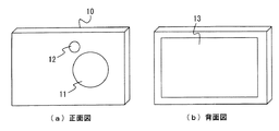
図1は本発明の第1の実施形態例に係る記録再生装置10の外観図である。この記録再生装置10は、携帯電話やPDA等のカメラ付の携帯情報表示端末、あるいはデジタルスチルカメラであり、筐体正面には図1(a)に示すように被写体からの被写体光を取り込むための撮影窓11と、被写体に向けて補助光を照射するための照明窓12が配設されている。また、この記録再生装置10の筐体背面には、図1(b)に示すように、LCDパネル等の画像表示装置13が配設されている。
FIG. 1 is an external view of a recording / reproducing
図2は、記録再生装置10の内部構成例を示したブロック図である。図2において、レンズ、絞り、フィルタ等を備えた光学部20(検出手段)から入力された撮像光は、イメージャ21(検出手段)等の撮像素子により光電変換されて、アナログデータをデジタルデータに変換するA/D変換部22に供給される。デジタルデータに変換された画像データは、静止画像データを圧縮処理する信号処理回路23により処理されて記録部28(記録手段)に記録される。
FIG. 2 is a block diagram showing an example of the internal configuration of the recording / reproducing
記録部28は、取り外し可能な記録メディアであっても、内蔵のハードディスクやフラッシュメモリであっても良い。撮影者は、電源スイッチ、シャッタ等を備える操作部26より、電源のON/OFFや撮像操作を行うことが可能である。
The
記録再生装置10は撮影モードと閲覧(再生)モードを持ち、画像再生時には、画像表示装置13を備えた表示部27(表示手段)により、記録部28に保存してある画像データを随時読み出して表示可能である。
The recording / reproducing
24は、後述する、光学部20およびイメージャ21により検出された人体部分又は物体、例えば手の、画像認識用の輪郭範囲の設定値、比較用のテンプレート画像や所定のパラメータ、プログラム等が記録された、書き換え可能なフラッシュメモリである。
25は、記録再生装置10内の処理を制御するCPU(表示切替手段)であり、前記フラッシュメモリ24より、随時必要なデータを読み出し、演算し、記録部28への書き込み処理等を行う。尚、図2において補助光を照射する光源等は図示省略している。
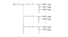
前記記録部28内のデータ構造は例えば図3のようになっており、画像データは撮影日時や撮影場所(GPS)ごとにグループ分けされた後、グループごとに記録される。たとえば、GPS搭載であれば、全ての画像データは撮影時のGPS情報をもとに、撮影場所ごとにグループ分けされているものとする。
The data structure in the
次に、記録再生装置10の閲覧モード時の表示画面及び操作方法を図4〜図16とともに説明する。尚図6はCPU25が実行する処理のフローチャートを示している。
Next, a display screen and an operation method in the browsing mode of the recording / reproducing
図4は記録再生装置10の閲覧モードにおける画像表示装置13の表示画面40を示している。表示画面40には、現在閲覧しているグループ41の画像データがサムネイル形式で画面中央に2列になって表示されている。グループ41のうち、点線で示されている部分は画面40の表示範囲外の部分であり、ユーザは、後述する、例えば仮想の手による直感的操作によって、グループ41を水平方向にスクロールさせることによって見ることができる。
FIG. 4 shows the
また、グループ41のグループ名48は、その作成日時・枚数と共に表示画面40上に表示されている。また、グループ41の一つ前のグループであるグループ42と、一つ後のグループであるグループ43が、グループ41の上下に放射状に表示されており、さらに、それらに続くグループ44〜グループ47も表示画面40の表示領域の外に放射状に配置されている。ユーザは後述する操作により、前記グループ全体を風車の羽根ように回転させることで、現在閲覧しているグループを順次変えることができる。
The
ここで、図6のステップS1において、図5(b)のように、記録再生装置10に対して表示装置13の反対面(撮影窓11、照明窓12側の面)に、ユーザが手50をかざすと、記録再生装置10に設けられた撮影窓11内の光学部20がその様子を画像として取り込む。
Here, in step S1 of FIG. 6, as shown in FIG. 5B, the user has a
この際、光学部20内のレンズはワイド端に固定されている。また、周囲が暗くユーザの手を撮影できない場合は、照明窓12から補助光を照射し、その光に照らされたユーザの手を撮影する。CPU25は、撮影窓11から撮像した画像信号を入力し、現在撮像中の範囲についての画像認識を利用した手位置検出を行う。適用可能な画像認識の手法としては、例えば、画像信号の色情報を基に肌色分布を検出して手の輪郭を含む範囲を特定し、あらかじめフラッシュメモリ24に記憶していた複数の手形態のテンプレートと比較して、手の存在の有無を判定する手法などが挙げられる。
At this time, the lens in the
ここで、図5(b)のように、ユーザがジェスチャとしてパー状態(第1の形状)で手50をかざすと、記録再生装置10に設けられた撮影窓11がその様子を画像として取り込み(ステップS1)、CPU25によってパー状態か否かが判定される(ステップS2)。そして、パー状態であると判定されると、チャートAを示す図7のステップS2−1において、図5(a)のように表示画面40にパー形状のアイコン51(第1のオブジェクト)を影がついた状態で表示する。この影は、アイコン51が表示画面40上のサムネイル画像に接触しておらず、この状態ではサムネイル画像を操作できないことを、ユーザに直感的に伝える効果を持つ。
Here, as shown in FIG. 5B, when the user holds the
この状態で、図7のステップS2−2において、手50が動いたか否かが判定される。そして図8(b)のように、矢印60の方向にユーザが手50を動かしたことが判定されると、図7のステップS2−3において、図8(a)の表示画面40上のアイコン51も、同様に矢印61の方向に動かす。矢印60の方向以外でも、ユーザが撮像範囲内で手50を動かせば、それに対応してアイコン51も表示画面40上で動く。また、手50が撮像範囲外に移動し、手が検出されなくなると、表示画面40上のアイコン51の表示を消し(図6のステップS5)、再度撮像範囲内に手50が入り、手が検出されると、表示画面40上にアイコン51を表示する(図7のステップS2−1)。
In this state, in step S2-2 in FIG. 7, it is determined whether or not the
また、図9(b)のように、ユーザが人差し指のみ垂直に立てた状態(第2の形状)で手70をかざすと、記録再生装置10に設けられた撮影窓11がその様子を画像として取り込み(ステップS1)、CPU25によって指差し状態(縦)か否かが判定される(ステップS3)。縦の指差し状態であると判定されると、チャートBを示す図10のステップS3−1において、図9(a)のように表示画面40に指差し形状(縦)のアイコン71(第2のオブジェクト)を影無しで表示する。ここで影がないことにより、アイコン71は表示画面40上のサムネイル画像に接触しており、サムネイル画像を操作可能であることをユーザに直感的に伝える効果を持つ。
Further, as shown in FIG. 9B, when the user holds the
この状態で、図10のステップS3−2において手70が動いたか否かが判定される。そして図11(b)のように、矢印80の方向にユーザが手70を動かしたことが判定されると、図10のステップS3−3において、図11(a)の表示画面40上のアイコン71も、同様に矢印81の方向に動かす。
In this state, it is determined whether or not the
さらに図10のステップS3−4において、手70が水平方向に動いたか否かが判定され、水平方向に動いた場合はステップS3−5において、表示画面40上のグループ41も水平にスクロールし、ユーザはグループ41の内容を容易に閲覧することができる。例えば、図9(a)において、表示画面40の表示範囲外にある画像72を見たい場合、ユーザは図11(b)のように水平方向80に手70を動かすことで、図11(a)のように表示画面40上のアイコン71が水平方向81に動き、画像72を表示画面40の表示範囲内へスクロールさせることができる。
Further, in step S3-4 in FIG. 10, it is determined whether or not the
また、図11(b)において、ユーザが矢印80と逆の方向に手70を動かした場合は、グループ41も水平方向81とは逆の向きにスクロールし、前記と逆向きに同様のスクロール操作が可能である。また、手70が撮像範囲外に移動し、手が検出されなくなると、表示画面40上のアイコン71の表示を消し(図6のステップS5)、再度撮像範囲内に手70が入り、手が検出されると、表示画面40上にアイコン71を表示する(図10のステップS3−1)。
In FIG. 11B, when the user moves the
また前記スクロールの際の特徴として、ユーザの手70を動かす速度がある閾値以上の場合、グループ41は慣性を持ってスクロールし続け、手70をスクロールと逆方向に動かすと、スクロールを止めることが出来る。ユーザの手70を動かす速度がある閾値以下の場合は、グループ41は手70の移動量に応じて一定量スクロールする。この閾値は予め設定されているが、ユーザが自身で設定できるようにしても良い。
Further, as a feature of the scroll, when the speed of moving the user's
このようにユーザの手70の移動速度に応じてスクロール速度を変更する処理は、例えば図6のチャートB´を示す図12のフローチャートに沿って実行される。
Thus, the process which changes scroll speed according to the moving speed of the user's
図12において、ステップS3−1〜S3−4は図10のステップS3−1〜S3−4と同一の処理を行う。次にステップS30−1において、ユーザの手70の移動速度が所定の閾値以上か否かを判定し、閾値以上である場合はステップS30−2において手70の移動方向を判定する。
In FIG. 12, steps S3-1 to S3-4 perform the same processing as steps S3-1 to S3-4 in FIG. Next, in step S30-1, it is determined whether or not the moving speed of the user's
手70の移動方向が右である場合は、ステップ30−3において表示画面40上のグループ41(サムネイル画像)を慣性をもって右方向へスクロールし続け、その後手70が左に動いたことがステップS30−4において判定されると前記スクロールを停止させる(ステップS30−5)。
If the moving direction of the
また手の移動方向が左である場合は、ステップ30−6において表示画面40上のグループ41(サムネイル画像)を慣性をもって左方向へスクロールし続け、その後手70が右に動いたことがステップS30−7において判定されると前記スクロールを停止させる(ステップS30−5)。
If the moving direction of the hand is left, in step 30-6, the group 41 (thumbnail image) on the
また前記ステップS30−1において、ユーザの手70の移動速度が閾値以上ではない場合は、ステップS30−8において手の移動方向が右であるか否かが判定される。
In step S30-1, if the moving speed of the user's
そして、手70の移動方向が右である場合は、ステップS30−9において表示画面40上のグループ41のサムネイル画像を手70の移動速度に比例した枚数分、右方向へスクロールし、手70の移動方向が左である場合は、ステップS30−10において表示画面40上のグループ41のサムネイル画像を手70の移動速度に比例した枚数分、左方向へスクロールする。
If the moving direction of the
また、図13(b)のように、ユーザが人差し指のみを水平に伸ばした状態(第3の形状)で手90をかざすと、記録再生装置10に設けられた撮影窓11がその様子を画像として取り込み(図6のステップS1)、CPU25によって指差し状態(横)か否かが判定される(ステップS4)。
As shown in FIG. 13B, when the user holds his / her
そして横の指差し状態であると判定されると、図6のチャートCを示す図14のステップS4−1において、図13(a)のように表示画面40に指差し形状のアイコン91(第3のオブジェクト)を影無しで表示する。ここで影がないことにより、アイコン91は表示画面40上のサムネイル画像に接触しており、サムネイル画像を操作可能であることをユーザに直感的に伝える効果を持つ。
If it is determined that the finger is in the horizontal pointing state, in step S4-1 in FIG. 14 showing the chart C in FIG. 6, the pointing icon 91 (the first icon 91) is displayed on the
この状態で図14のステップS4−2において手90が動いたか否かが判定される。そして図15(b)のように、矢印100の方向にユーザが手90を動かしたことが判定されると、図14のステップS4−3において、図15(a)の表示画面40上のアイコン91も、同様に矢印101方向に動かす。
In this state, it is determined whether or not the
さらに図14のステップS4−4において手90が垂直方向に動いたか否かが判定され、垂直方向に動いた場合はステップS4−5において、表示画面40上のグループ41を図15の回転方向103に沿って回転させ、図13のグループ43のあった場所に移動させる。また同時に、図13のグループ42は図15の回転方向102に沿って回転し、図13のグループ41のあった場所に移動し、図13のグループ42のあった場所には、その次のグループであるグループ44が表示画面40外から回転してきて表示される。そして最後に、グループ42のグループ名104が表示画面40上に表示される。
Further, in step S4-4 in FIG. 14, it is determined whether or not the
上記の操作により、ユーザは閲覧中のグループを図13に示すグループ41から図15に示すグループ42に変更することができる。例えば、図13(a)において、グループ42にある画像92を見たい場合、ユーザが図15(b)のように垂直方向100に手90を動かすことで、図15(a)のように表示画面40上のアイコン91が垂直方向101に動き、それに伴いグループ42が矢印102の方向に回転し、中央の閲覧中のグループとなることで、画像92を見ることができる。
Through the above operation, the user can change the group being browsed from the
また、図15(b)において、手90を垂直方向100の向きと逆に動かした場合、表示画面40上のアイコン91も垂直方向101と逆に動き、それに伴いグループ41は回転方向102と逆向きに回転した後、グループ42のあった場所に移動する。即ち、前記と逆向きに同様の操作で、グループを切り替えることが可能である。また、手90が撮像範囲外に移動し、手が検出されなくなると、表示画面40上のアイコン91の表示を消し(図6のステップS5)、再度撮像範囲内に手90が入り、手が検出されると、表示画面40上にアイコン91を表示する(図14のステップS4−1)。
15B, when the
また前記グループを切り替える際の操作の特徴として、図15(b)において、ユーザの手90を動かす速度がある閾値以上の場合、各グループは慣性を持って回転し続け、手90を回転と逆方向に動かすと、回転を止めることが出来る。ユーザの手90を動かす速度がある閾値以下の場合は、各グループは手90の移動量に応じて一定回数(回転角度)回転する。上記の閾値は予め設定されているが、ユーザが自身で設定できるようにしても良い。
Further, as a feature of the operation when switching the groups, in FIG. 15B, when the speed of moving the user's
このようにユーザの手90の移動速度に応じて各グループの回転速度を変更する処理は、例えば図6のチャートC´を示す図16のフローチャートに沿って実行される。
Thus, the process which changes the rotational speed of each group according to the moving speed of the user's
図16において、ステップS4−1〜S4−4は図14のステップS4−1〜S4−4と同一の処理を行う。次にステップS40−1において、ユーザの手90の移動速度が所定の閾値以上か否かを判定し、閾値以上である場合はステップS40−2において手90の移動方向を判定する。
In FIG. 16, steps S4-1 to S4-4 perform the same processing as steps S4-1 to S4-4 in FIG. Next, in step S40-1, it is determined whether or not the moving speed of the user's
手90の移動方向が下向きである場合は、ステップ40−3において表示画面40上のグループ全体を慣性をもって下方向へ回転させ、その後手90が上に動いたことがステップS40−4において判定されると前記回転を停止させる(ステップS40−5)。
If the movement direction of the
また手の移動方向が上である場合は、ステップ40−6において表示画面40上のグループ全体を慣性をもって上方向へ回転させ続け、その後手90が下に動いたことがステップS40−7において判定されると前記回転を停止させる(ステップS40−5)。
If the moving direction of the hand is upward, it is determined in step S40-7 that the entire group on the
また前記ステップS40−1において、ユーザの手90の移動速度が閾値以上ではない場合は、ステップS40−8において手の移動方向が下向きであるか否かが判定される。
In step S40-1, if the moving speed of the user's
そして、手90の移動方向が下向きである場合は、ステップS40−9において表示画面40上のグループ全体を手90の移動速度に比例した分、下方向へ回転し、手90の移動方向が上方向である場合は、ステップS40−10において表示画面40上のグループ全体を手90の移動速度に比例した分、上方向へ回転させる。
If the moving direction of the
また、ユーザが上記のパー状態、指差し状態(縦)及び指差し状態(横)以外の形で、手をかざした場合、記録再生装置10に設けられた撮影窓11がその様子を画像として取り込み(図6のステップS1)、CPU25によって上記の3状態以外であると認識され(図6のステップS2〜S4)、表示画面40上の手のアイコンを消去する(図6のステップS5)。この状態では、ユーザは表示画面40上のグループ及び画像に対してスクロール及び回転操作ができず、画面40上の画像をゆっくり閲覧することができる。
Further, when the user holds his / her hand in a form other than the par state, the pointing state (vertical), and the pointing state (horizontal), the shooting
また、上記の実施例では、GPSによる位置情報を用いたグループ分けをおこなったが、グループ分けの手法はこれに限らず、例えば、日時やWi-Fi(無線LAN)による位置情報、画像の顔認識による特徴分析等を基にグループ分けを行っても良い。 In the above embodiment, the grouping using the position information by GPS is performed. However, the grouping method is not limited to this. For example, the position information by date and time, Wi-Fi (wireless LAN), the face of the image, etc. Grouping may be performed based on feature analysis based on recognition.
次に、図17乃至図19を参照して、本発明の第2の実施形態例を説明する。 Next, a second embodiment of the present invention will be described with reference to FIGS.
図17(b)のように、記録再生装置110は画像表示装置111を具備する携帯電話やPDA等のカメラ付の携帯情報表示端末、あるいはデジタルスチルカメラである。画像表示装置111はバックライト付の液晶表示兼撮像装置であり、同装置は液晶のTFTトランジスタ内に微少な光センサを形成しており、画像表示装置111上に物体がかざされると、液晶部の光センサが物体の形状を画像として取り込むことが可能である。また、暗所においてもバックライトの照射光によって物体を照らし、その反射光により画像を得ることが可能である。
As shown in FIG. 17B, the recording / reproducing
本実施形態例の記録再生装置110の内部構成は図2と略同様に構成されるが、A/D変換部22の入力側には図2の光学部20およびイメージャ21の出力の代わりに、前記液晶部の光センサの検出信号を取り込む構成となっている。
The internal configuration of the recording / reproducing
図17(a)に、記録再生装置110の閲覧モードにおける画像表示装置111の表示画面40を示す。この表示画面40は、第1の実施形態例とまったく同一である。
FIG. 17A shows the
ここで、図17(b)のように、記録再生装置110に対して画像表示装置111上に、ユーザがパーの状態で手50をかざすと、画像表示装置111がその様子を画像として取り込む。CPU25は、画像表示装置111が取り込んだ画像信号を入力し、現在撮像中の範囲についての画像認識を利用した手位置検出を行う。適用可能な画像認識の手法としては、前記同様に例えば、画像信号の色情報を基に肌色分布を検出して手の輪郭を含む範囲を特定し、あらかじめ記憶していた複数の手形態のテンプレートと比較して、手の存在の有無を判定する手法などが挙げられる。こうしてユーザのパー状態の手50が検出された場合、図17(a)のように表示画面40にパー形状のアイコン51を影がついた状態で表示する。パー状態での表示画面40上の操作方法に関しては前記図6〜図8の動作と同じであるので、ここでは説明を省く。
Here, as shown in FIG. 17B, when the user holds his / her
また、図18(b)のように、ユーザが人差し指のみを垂直に立てた状態で手70をかざすと、記録再生装置110に設けられた画像表示装置111がその様子を画像として取り込み、CPU25によって指差し状態(縦)として検出される。そして、図18(a)のように表示画面40に指差し状態(縦)のアイコン71を影無しで表示する。指差し状態(縦)での表示画面40上の操作方法に関しては前記図9〜図12の動作と同じであるので、ここでは説明を省く。
Further, as shown in FIG. 18B, when the user holds his / her
また図19(b)のように、ユーザが人差し指のみを水平に伸ばした状態で手90をかざすと、記録再生装置110に設けられた画像表示装置111がその様子を画像として取り込み、CPU25によって指差し状態(横)として検出される。そして、図19(a)のように表示画面40に指差し状態(横)のアイコン91を影無しで表示する。指差し状態(横)の操作に関しては前記図13〜図16の動作と同じであるので、ここでは説明を省く。
Further, as shown in FIG. 19B, when the user holds his
また、ユーザが上記のパー状態、指差し状態(縦)及び指差し状態(横)以外の形で、手をかざした場合、記録再生装置110に設けられた画像表示装置111がその様子を画像として取り込み、CPU25によって上記の3状態以外であると認識され、表示画面40上の手のアイコンを消去する(図6のフローチャート)。この状態では、前記第1の実施形態例の場合と同様に、ユーザは表示画面40上のグループ及び画像に対してスクロール及び回転操作ができず、表示画面40上の画像をゆっくり閲覧することができる。
Further, when the user holds his / her hand in a form other than the par state, the pointing state (vertical), and the pointing state (horizontal), the
尚、表示画面40上での画像の切り替え(グループのスクロール、グループ全体の回転)はユーザの手50,70,90の3つの形状によるものに限らず、他の形状、例えば、グー、チョキ状態を用いてもよく、また形状の異なる複数の物体を用いてもよい。
The switching of images on the display screen 40 (group scrolling, rotation of the entire group) is not limited to the three shapes of the user's
10,110…記録再生装置、11…撮影窓、12…照明窓、13,111…画像表示装置、20…光学部、21…イメージャ、22…A/D変換部、23…信号処理回路、24…フラッシュメモリ、25…CPU、26…操作部、27…表示部、28…記録部、40…表示画面、41〜47…グループ、48…グループ名、50,70,90…手、51…影つきのアイコン、71,91…影無しのアイコン。 DESCRIPTION OF SYMBOLS 10,110 ... Recording / reproducing apparatus, 11 ... Shooting window, 12 ... Illumination window, 13,111 ... Image display apparatus, 20 ... Optical part, 21 ... Imager, 22 ... A / D conversion part, 23 ... Signal processing circuit, 24 ... Flash memory, 25 ... CPU, 26 ... Operating section, 27 ... Display section, 28 ... Recording section, 40 ... Display screen, 41-47 ... Group, 48 ... Group name, 50, 70, 90 ... Hand, 51 ... Shadow Attached icons, 71, 91 ... Icons without shadows.
Claims (11)
自装置の筐体の一面に設けられた表示領域に前記複数の画像を表示する表示手段と、
前記筐体の一面とは反対の面に設けられた検出領域に近接して位置する第1形状の操作体を検出する検出手段と、
前記第1形状の操作体が検出されると、前記第1形状の操作体に対応するオブジェクトを前記表示領域に表示し、さらに前記第1形状の操作体の移動が検出されると、前記操作体の形状毎に定められた移動パターンに従って、前記第1形状の操作体の移動に連動して、前記表示領域上で前記複数の画像を基準点に対して回転させて表示する表示制御手段と
を備える携帯型表示装置。 Recording means for recording a plurality of images;
And Table Shimesuru display means said plurality of images on a display region provided on one surface of the housing of the apparatus,
Detecting means for detecting a first shape operating body located in the vicinity of a detection region provided on a surface opposite to the one surface of the housing;
When the operation of the first shape is detected, the object corresponding to the operation of the first shape is displayed on the display area, further movement of the operator of the first shape is detected, the operation Display control means for rotating and displaying the plurality of images with respect to a reference point on the display area in conjunction with movement of the first shape operating body according to a movement pattern determined for each body shape; A portable display device comprising:
前記表示制御手段は、前記第1形状の操作体の移動速度が閾値以上である場合に、前記表示領域上で前記複数の画像を前記基準点に対して慣性を伴って回転させて表示する、請求項1に記載の携帯型表示装置。 Further comprising a calculating means for calculating a moving speed of the operation of the first shape to be moved in proximity to the detection area,
It said display control means, when the moving speed of the operation of the first shape is greater than or equal to the threshold value, rotate and displays with a inertial for the plurality of images said reference point on said display area The portable display device according to claim 1 .
前記表示制御手段は、前記第2形状の操作体が検出されると、前記第2形状の操作体に対応するオブジェクトを前記表示領域に表示し、さらに前記第2形状の操作体の移動が検出されると、前記第2形状の操作体の移動に連動して、前記表示領域上で前記複数の画像をスクロールさせて表示する、請求項1に記載の携帯型表示装置。 Before Symbol detection means detects the operation of the different second shape and the first shape, located in proximity to the detection area,
Said display control means, when the operation of the second shape is detected, the object corresponding to the operation of the second shape displayed on the display area, further movement of the second shape of the operating body Once detected, the in conjunction with the movement of the second shape operating body, the display region scan to crawl the plurality of images displayed, the portable display device according to claim 1.
前記表示制御手段は、前記第2形状の操作体の移動速度が閾値以上である場合に、前記表示領域上で前記複数の画像を慣性を伴ってスクロールさせて表示する、請求項4に記載の携帯型表示装置。 Further comprising a calculating means for calculating a moving speed of the operation of the second shape which moves in proximity to the detection area,
Said display control means, when the moving speed of the operation of the second shape is not less than the threshold value, the plurality of images on the display area to display by scrolling with the inertia, to claim 4 The portable display device described.
自装置の筐体の一面に設けられた表示領域に複数の画像を表示し、
前記筐体の一面とは反対の面に設けられた検出領域に近接して位置する第1形状の操作体を検出し、
前記第1形状の操作体が検出されると、前記第1形状の操作体に対応するオブジェクトを前記表示領域に表示し、さらに前記第1形状の操作体の移動が検出されると、前記操作体の形状毎に定められた移動パターンに従って、前記第1形状の操作体の移動に連動して、前記表示領域上で前記複数の画像を基準点に対して回転させて表示すること
を含む表示方法。 In a portable display device,
A plurality of images on a display region provided on one surface of the housing of the apparatus and Viewing,
Wherein the one surface of the housing to detect the operation of the first shape located proximate to the detection area on the opposite side,
When the operation of the first shape is detected, the object corresponding to the operation of the first shape is displayed on the display area, further movement of the operator of the first shape is detected, the operation according to the movement pattern defined for each shape of the body, in conjunction with the movement of the operator of the first shape, the display comprises displaying rotated relative to a reference point of the plurality of images on said display region Method.
自装置の筐体の一面に設けられた表示領域に複数の画像を表示し、
前記筐体の一面とは反対の面に設けられた検出領域に近接して位置する第1形状の操作体を検出し、
前記第1形状の操作体が検出されると、前記第1形状の操作体に対応するオブジェクトを前記表示領域に表示し、さらに前記第1形状の操作体の移動が検出されると、前記操作体の形状毎に定められた移動パターンに従って、前記第1形状の操作体の移動に連動して、前記表示領域上で前記複数の画像を基準点に対して回転させて表示すること
を含む表示方法をコンピュータに実行させるためのプログラム。
In a portable display device,
A plurality of images on a display region provided on one surface of the housing of the apparatus and Viewing,
Wherein the one surface of the housing to detect the operation of the first shape located proximate to the detection area on the opposite side,
When the operation of the first shape is detected, the object corresponding to the operation of the first shape is displayed on the display area, further movement of the operator of the first shape is detected, the operation according to the movement pattern defined for each shape of the body, in conjunction with the movement of the operator of the first shape, the display comprises displaying rotated relative to a reference point of the plurality of images on said display region A program for causing a computer to execute the method.
Priority Applications (3)
| Application Number | Priority Date | Filing Date | Title |
|---|---|---|---|
| JP2007302555A JP4670860B2 (en) | 2007-11-22 | 2007-11-22 | Recording / playback device |
| US12/272,017 US8872760B2 (en) | 2007-11-22 | 2008-11-17 | Recording and reproducing apparatus |
| US14/497,456 US9529444B2 (en) | 2007-11-22 | 2014-09-26 | Recording and reproducing apparatus |
Applications Claiming Priority (1)
| Application Number | Priority Date | Filing Date | Title |
|---|---|---|---|
| JP2007302555A JP4670860B2 (en) | 2007-11-22 | 2007-11-22 | Recording / playback device |
Publications (2)
| Publication Number | Publication Date |
|---|---|
| JP2009129142A JP2009129142A (en) | 2009-06-11 |
| JP4670860B2 true JP4670860B2 (en) | 2011-04-13 |
Family
ID=40669285
Family Applications (1)
| Application Number | Title | Priority Date | Filing Date |
|---|---|---|---|
| JP2007302555A Expired - Fee Related JP4670860B2 (en) | 2007-11-22 | 2007-11-22 | Recording / playback device |
Country Status (2)
| Country | Link |
|---|---|
| US (2) | US8872760B2 (en) |
| JP (1) | JP4670860B2 (en) |
Cited By (1)
| Publication number | Priority date | Publication date | Assignee | Title |
|---|---|---|---|---|
| WO2013175847A1 (en) | 2012-05-22 | 2013-11-28 | ソニー株式会社 | Image processing device, image processing method, and program |
Families Citing this family (38)
| Publication number | Priority date | Publication date | Assignee | Title |
|---|---|---|---|---|
| US7459624B2 (en) | 2006-03-29 | 2008-12-02 | Harmonix Music Systems, Inc. | Game controller simulating a musical instrument |
| EP2206540A1 (en) | 2007-06-14 | 2010-07-14 | Harmonix Music Systems, Inc. | System and method for simulating a rock band experience |
| US8678896B2 (en) | 2007-06-14 | 2014-03-25 | Harmonix Music Systems, Inc. | Systems and methods for asynchronous band interaction in a rhythm action game |
| WO2010006054A1 (en) | 2008-07-08 | 2010-01-14 | Harmonix Music Systems, Inc. | Systems and methods for simulating a rock and band experience |
| US8465366B2 (en) | 2009-05-29 | 2013-06-18 | Harmonix Music Systems, Inc. | Biasing a musical performance input to a part |
| US9981193B2 (en) | 2009-10-27 | 2018-05-29 | Harmonix Music Systems, Inc. | Movement based recognition and evaluation |
| WO2011056657A2 (en) * | 2009-10-27 | 2011-05-12 | Harmonix Music Systems, Inc. | Gesture-based user interface |
| US8702485B2 (en) | 2010-06-11 | 2014-04-22 | Harmonix Music Systems, Inc. | Dance game and tutorial |
| KR101224035B1 (en) * | 2009-12-14 | 2013-01-18 | 주식회사 케이티 | Apparatus and method for displaying background image |
| US8874243B2 (en) | 2010-03-16 | 2014-10-28 | Harmonix Music Systems, Inc. | Simulating musical instruments |
| JP4943527B2 (en) * | 2010-03-25 | 2012-05-30 | シャープ株式会社 | Image display operation device and image forming apparatus having the same |
| KR101743948B1 (en) | 2010-04-07 | 2017-06-21 | 삼성전자주식회사 | Method for hover sensing in the interactive display and method for processing hover sensing image |
| US8562403B2 (en) | 2010-06-11 | 2013-10-22 | Harmonix Music Systems, Inc. | Prompting a player of a dance game |
| US9358456B1 (en) | 2010-06-11 | 2016-06-07 | Harmonix Music Systems, Inc. | Dance competition game |
| US9134800B2 (en) * | 2010-07-20 | 2015-09-15 | Panasonic Intellectual Property Corporation Of America | Gesture input device and gesture input method |
| US9024166B2 (en) | 2010-09-09 | 2015-05-05 | Harmonix Music Systems, Inc. | Preventing subtractive track separation |
| JP2012089112A (en) * | 2010-09-22 | 2012-05-10 | Nikon Corp | Image display device |
| US8854802B2 (en) | 2010-10-22 | 2014-10-07 | Hewlett-Packard Development Company, L.P. | Display with rotatable display screen |
| US9489102B2 (en) * | 2010-10-22 | 2016-11-08 | Hewlett-Packard Development Company, L.P. | System and method of modifying lighting in a display system |
| US20120102439A1 (en) * | 2010-10-22 | 2012-04-26 | April Slayden Mitchell | System and method of modifying the display content based on sensor input |
| US9164581B2 (en) | 2010-10-22 | 2015-10-20 | Hewlett-Packard Development Company, L.P. | Augmented reality display system and method of display |
| JP5479414B2 (en) * | 2010-11-24 | 2014-04-23 | キヤノン株式会社 | Information processing apparatus and control method thereof |
| US20120194415A1 (en) * | 2011-01-31 | 2012-08-02 | Honeywell International Inc. | Displaying an image |
| US20120194692A1 (en) * | 2011-01-31 | 2012-08-02 | Hand Held Products, Inc. | Terminal operative for display of electronic record |
| US8717318B2 (en) * | 2011-03-29 | 2014-05-06 | Intel Corporation | Continued virtual links between gestures and user interface elements |
| US9417703B2 (en) | 2011-04-20 | 2016-08-16 | Koninklijke Philips N.V. | Gesture based control of element or item |
| JP5994434B2 (en) * | 2011-10-07 | 2016-09-21 | カシオ計算機株式会社 | Electronic device and program |
| USD748136S1 (en) * | 2013-02-23 | 2016-01-26 | Samsung Electronics Co., Ltd. | Display screen or portion thereof with icon |
| US10220303B1 (en) | 2013-03-15 | 2019-03-05 | Harmonix Music Systems, Inc. | Gesture-based music game |
| KR20150110032A (en) * | 2014-03-24 | 2015-10-02 | 삼성전자주식회사 | Electronic Apparatus and Method for Image Data Processing |
| US10782787B2 (en) * | 2014-06-06 | 2020-09-22 | Adobe Inc. | Mirroring touch gestures |
| JP6447179B2 (en) * | 2015-01-28 | 2019-01-09 | 富士ゼロックス株式会社 | Information input system and input device |
| CN104714642A (en) * | 2015-03-02 | 2015-06-17 | 惠州Tcl移动通信有限公司 | Mobile terminal and gesture recognition processing method and system thereof |
| JP6354653B2 (en) * | 2015-04-25 | 2018-07-11 | 京セラドキュメントソリューションズ株式会社 | Augmented reality operation system and augmented reality operation program |
| US10558278B2 (en) | 2017-07-11 | 2020-02-11 | Apple Inc. | Interacting with an electronic device through physical movement |
| US10937240B2 (en) | 2018-01-04 | 2021-03-02 | Intel Corporation | Augmented reality bindings of physical objects and virtual objects |
| JP7155613B2 (en) * | 2018-05-29 | 2022-10-19 | 富士フイルムビジネスイノベーション株式会社 | Information processing device and program |
| US20220374085A1 (en) * | 2021-05-19 | 2022-11-24 | Apple Inc. | Navigating user interfaces using hand gestures |
Citations (10)
| Publication number | Priority date | Publication date | Assignee | Title |
|---|---|---|---|---|
| JPH03122736U (en) * | 1990-03-29 | 1991-12-13 | ||
| JPH0784714A (en) * | 1993-06-29 | 1995-03-31 | Casio Comput Co Ltd | Command processor |
| JPH09185456A (en) * | 1995-04-28 | 1997-07-15 | Matsushita Electric Ind Co Ltd | Interface device |
| JP2000105772A (en) * | 1998-07-28 | 2000-04-11 | Sharp Corp | Information managing device |
| JP2000187554A (en) * | 1998-12-24 | 2000-07-04 | Casio Comput Co Ltd | Input device |
| JP2003330611A (en) * | 2002-05-16 | 2003-11-21 | Sony Corp | Input method and input device |
| JP2004104594A (en) * | 2002-09-11 | 2004-04-02 | Toshiba Corp | Digital still camera and method for inputting user instruction |
| JP2006040050A (en) * | 2004-07-28 | 2006-02-09 | Olympus Corp | Reproduction device, camera and display switching method for reproduction device |
| JP2006323260A (en) * | 2005-05-20 | 2006-11-30 | Mitsubishi Electric Corp | Display device incorporating optical sensor |
| JP2007128497A (en) * | 2005-10-05 | 2007-05-24 | Sony Corp | Display apparatus and method thereof |
Family Cites Families (7)
| Publication number | Priority date | Publication date | Assignee | Title |
|---|---|---|---|---|
| JPH03122736A (en) | 1989-10-05 | 1991-05-24 | Toshiba Corp | Data processor |
| US5594469A (en) * | 1995-02-21 | 1997-01-14 | Mitsubishi Electric Information Technology Center America Inc. | Hand gesture machine control system |
| CN1183151A (en) * | 1995-04-28 | 1998-05-27 | 松下电器产业株式会社 | Interface device |
| JPH09237151A (en) | 1996-03-01 | 1997-09-09 | Gijutsu Kenkyu Kumiai Shinjoho Shiyori Kaihatsu Kiko | Graphical user interface |
| US6501515B1 (en) * | 1998-10-13 | 2002-12-31 | Sony Corporation | Remote control system |
| JP3122736B2 (en) | 1999-03-24 | 2001-01-09 | 財団法人地球環境産業技術研究機構 | Bipolar plate for water electrolysis tank and method for producing the same |
| WO2006074266A2 (en) * | 2005-01-05 | 2006-07-13 | Hillcrest Laboratories, Inc. | Scaling and layout methods and systems for handling one-to-many objects |
-
2007
- 2007-11-22 JP JP2007302555A patent/JP4670860B2/en not_active Expired - Fee Related
-
2008
- 2008-11-17 US US12/272,017 patent/US8872760B2/en active Active
-
2014
- 2014-09-26 US US14/497,456 patent/US9529444B2/en active Active
Patent Citations (10)
| Publication number | Priority date | Publication date | Assignee | Title |
|---|---|---|---|---|
| JPH03122736U (en) * | 1990-03-29 | 1991-12-13 | ||
| JPH0784714A (en) * | 1993-06-29 | 1995-03-31 | Casio Comput Co Ltd | Command processor |
| JPH09185456A (en) * | 1995-04-28 | 1997-07-15 | Matsushita Electric Ind Co Ltd | Interface device |
| JP2000105772A (en) * | 1998-07-28 | 2000-04-11 | Sharp Corp | Information managing device |
| JP2000187554A (en) * | 1998-12-24 | 2000-07-04 | Casio Comput Co Ltd | Input device |
| JP2003330611A (en) * | 2002-05-16 | 2003-11-21 | Sony Corp | Input method and input device |
| JP2004104594A (en) * | 2002-09-11 | 2004-04-02 | Toshiba Corp | Digital still camera and method for inputting user instruction |
| JP2006040050A (en) * | 2004-07-28 | 2006-02-09 | Olympus Corp | Reproduction device, camera and display switching method for reproduction device |
| JP2006323260A (en) * | 2005-05-20 | 2006-11-30 | Mitsubishi Electric Corp | Display device incorporating optical sensor |
| JP2007128497A (en) * | 2005-10-05 | 2007-05-24 | Sony Corp | Display apparatus and method thereof |
Cited By (2)
| Publication number | Priority date | Publication date | Assignee | Title |
|---|---|---|---|---|
| WO2013175847A1 (en) | 2012-05-22 | 2013-11-28 | ソニー株式会社 | Image processing device, image processing method, and program |
| US10360706B2 (en) | 2012-05-22 | 2019-07-23 | Sony Corporation | Device method and program for adjusting a display state of a superimposed image |
Also Published As
| Publication number | Publication date |
|---|---|
| US8872760B2 (en) | 2014-10-28 |
| US20090135135A1 (en) | 2009-05-28 |
| JP2009129142A (en) | 2009-06-11 |
| US9529444B2 (en) | 2016-12-27 |
| US20150012894A1 (en) | 2015-01-08 |
Similar Documents
| Publication | Publication Date | Title |
|---|---|---|
| JP4670860B2 (en) | Recording / playback device | |
| US10152222B2 (en) | Digital image processing device and associated methodology of performing touch-based image scaling | |
| JP3977684B2 (en) | Digital still camera | |
| US8760418B2 (en) | Display control apparatus, display control method and display control program | |
| JP5259315B2 (en) | Image search device, digital camera, image search method, and image search program | |
| RU2541852C2 (en) | Device and method of controlling user interface based on movements | |
| US20160170585A1 (en) | Display control device, method and computer program product | |
| US20120154305A1 (en) | Image display control apparatus and image display control method | |
| US20110063236A1 (en) | Information processing device, display method and program | |
| JP2005234993A (en) | Image display device and image display method | |
| US20100103136A1 (en) | Image display device, image display method, and program product | |
| JP2008204402A (en) | User interface device | |
| WO2006036069A1 (en) | Information processing system and method | |
| EP1014708A2 (en) | Image-capturing device | |
| US20100097337A1 (en) | Method for operating page and electronic device | |
| JP2009140368A (en) | Input device, display device, input method, display method, and program | |
| US20130088429A1 (en) | Apparatus and method for recognizing user input | |
| KR20110074663A (en) | Information processing apparatus and control method therefor | |
| JP2009187426A (en) | Recording and reproducing device | |
| WO2016196988A1 (en) | Quick review of captured image data | |
| CN112714253B (en) | Video recording method and device, electronic equipment and readable storage medium | |
| JP4190935B2 (en) | Mobile terminal device | |
| JP2005025268A (en) | Electronic device and method for controlling display | |
| KR101126867B1 (en) | Photographing method of wireless terminal capable of photographing shot mode using touch pattern | |
| CN112492205B (en) | Image preview method and device and electronic equipment |
Legal Events
| Date | Code | Title | Description |
|---|---|---|---|
| A977 | Report on retrieval |
Free format text: JAPANESE INTERMEDIATE CODE: A971007 Effective date: 20091225 |
|
| A131 | Notification of reasons for refusal |
Free format text: JAPANESE INTERMEDIATE CODE: A131 Effective date: 20100105 |
|
| A521 | Request for written amendment filed |
Free format text: JAPANESE INTERMEDIATE CODE: A523 Effective date: 20100301 |
|
| A131 | Notification of reasons for refusal |
Free format text: JAPANESE INTERMEDIATE CODE: A131 Effective date: 20100622 |
|
| A521 | Request for written amendment filed |
Free format text: JAPANESE INTERMEDIATE CODE: A523 Effective date: 20100706 |
|
| TRDD | Decision of grant or rejection written | ||
| A01 | Written decision to grant a patent or to grant a registration (utility model) |
Free format text: JAPANESE INTERMEDIATE CODE: A01 Effective date: 20101221 |
|
| A01 | Written decision to grant a patent or to grant a registration (utility model) |
Free format text: JAPANESE INTERMEDIATE CODE: A01 |
|
| A61 | First payment of annual fees (during grant procedure) |
Free format text: JAPANESE INTERMEDIATE CODE: A61 Effective date: 20110103 |
|
| R151 | Written notification of patent or utility model registration |
Ref document number: 4670860 Country of ref document: JP Free format text: JAPANESE INTERMEDIATE CODE: R151 |
|
| FPAY | Renewal fee payment (event date is renewal date of database) |
Free format text: PAYMENT UNTIL: 20140128 Year of fee payment: 3 |
|
| R250 | Receipt of annual fees |
Free format text: JAPANESE INTERMEDIATE CODE: R250 |
|
| R250 | Receipt of annual fees |
Free format text: JAPANESE INTERMEDIATE CODE: R250 |
|
| R250 | Receipt of annual fees |
Free format text: JAPANESE INTERMEDIATE CODE: R250 |
|
| R250 | Receipt of annual fees |
Free format text: JAPANESE INTERMEDIATE CODE: R250 |
|
| R250 | Receipt of annual fees |
Free format text: JAPANESE INTERMEDIATE CODE: R250 |
|
| R250 | Receipt of annual fees |
Free format text: JAPANESE INTERMEDIATE CODE: R250 |
|
| R250 | Receipt of annual fees |
Free format text: JAPANESE INTERMEDIATE CODE: R250 |
|
| LAPS | Cancellation because of no payment of annual fees |