EP2139095A2 - Power tool including hybrid electric motor design - Google Patents
Power tool including hybrid electric motor design Download PDFInfo
- Publication number
- EP2139095A2 EP2139095A2 EP09251644A EP09251644A EP2139095A2 EP 2139095 A2 EP2139095 A2 EP 2139095A2 EP 09251644 A EP09251644 A EP 09251644A EP 09251644 A EP09251644 A EP 09251644A EP 2139095 A2 EP2139095 A2 EP 2139095A2
- Authority
- EP
- European Patent Office
- Prior art keywords
- housing
- motor
- motor housing
- power tool
- armature
- Prior art date
- Legal status (The legal status is an assumption and is not a legal conclusion. Google has not performed a legal analysis and makes no representation as to the accuracy of the status listed.)
- Granted
Links
Images


Classifications
-
- H—ELECTRICITY
- H02—GENERATION; CONVERSION OR DISTRIBUTION OF ELECTRIC POWER
- H02K—DYNAMO-ELECTRIC MACHINES
- H02K5/00—Casings; Enclosures; Supports
- H02K5/04—Casings or enclosures characterised by the shape, form or construction thereof
- H02K5/16—Means for supporting bearings, e.g. insulating supports or means for fitting bearings in the bearing-shields
- H02K5/167—Means for supporting bearings, e.g. insulating supports or means for fitting bearings in the bearing-shields using sliding-contact or spherical cap bearings
- H02K5/1672—Means for supporting bearings, e.g. insulating supports or means for fitting bearings in the bearing-shields using sliding-contact or spherical cap bearings radially supporting the rotary shaft at both ends of the rotor
-
- B—PERFORMING OPERATIONS; TRANSPORTING
- B25—HAND TOOLS; PORTABLE POWER-DRIVEN TOOLS; MANIPULATORS
- B25F—COMBINATION OR MULTI-PURPOSE TOOLS NOT OTHERWISE PROVIDED FOR; DETAILS OR COMPONENTS OF PORTABLE POWER-DRIVEN TOOLS NOT PARTICULARLY RELATED TO THE OPERATIONS PERFORMED AND NOT OTHERWISE PROVIDED FOR
- B25F5/00—Details or components of portable power-driven tools not particularly related to the operations performed and not otherwise provided for
- B25F5/02—Construction of casings, bodies or handles
-
- H—ELECTRICITY
- H02—GENERATION; CONVERSION OR DISTRIBUTION OF ELECTRIC POWER
- H02K—DYNAMO-ELECTRIC MACHINES
- H02K5/00—Casings; Enclosures; Supports
- H02K5/04—Casings or enclosures characterised by the shape, form or construction thereof
- H02K5/14—Means for supporting or protecting brushes or brush holders
- H02K5/143—Means for supporting or protecting brushes or brush holders for cooperation with commutators
- H02K5/145—Fixedly supported brushes or brush holders, e.g. leaf or leaf-mounted brushes
-
- H—ELECTRICITY
- H02—GENERATION; CONVERSION OR DISTRIBUTION OF ELECTRIC POWER
- H02K—DYNAMO-ELECTRIC MACHINES
- H02K7/00—Arrangements for handling mechanical energy structurally associated with dynamo-electric machines, e.g. structural association with mechanical driving motors or auxiliary dynamo-electric machines
- H02K7/08—Structural association with bearings
- H02K7/083—Structural association with bearings radially supporting the rotary shaft at both ends of the rotor
-
- H—ELECTRICITY
- H02—GENERATION; CONVERSION OR DISTRIBUTION OF ELECTRIC POWER
- H02K—DYNAMO-ELECTRIC MACHINES
- H02K7/00—Arrangements for handling mechanical energy structurally associated with dynamo-electric machines, e.g. structural association with mechanical driving motors or auxiliary dynamo-electric machines
- H02K7/14—Structural association with mechanical loads, e.g. with hand-held machine tools or fans
- H02K7/145—Hand-held machine tool
-
- H—ELECTRICITY
- H02—GENERATION; CONVERSION OR DISTRIBUTION OF ELECTRIC POWER
- H02K—DYNAMO-ELECTRIC MACHINES
- H02K9/00—Arrangements for cooling or ventilating
- H02K9/02—Arrangements for cooling or ventilating by ambient air flowing through the machine
- H02K9/04—Arrangements for cooling or ventilating by ambient air flowing through the machine having means for generating a flow of cooling medium
- H02K9/06—Arrangements for cooling or ventilating by ambient air flowing through the machine having means for generating a flow of cooling medium with fans or impellers driven by the machine shaft
Definitions
- the present invention relates to power tools, and more particularly to electric motors for use with power tools.
- Can motors typically include a housing in the form of a cylindrical can in which essentially all of the components of the motor are received, including the armature, magnets, brushes, motor housing, fan, and bearings.
- Most DC battery-powered tools incorporate a can motor to drive the power tool output due to the simplicity of assembly and low cost of can motors.
- Can motors are often preassembled, thereby simplifying assembly of the can motors in power tools. Because the motor components are disposed within a can, a can motor can be operated without the motor being mounted in a product.
- can motors include several mounting holes on the front of the can to facilitate attachment to a product or gear train. Such mounting holes on the front of the can simplifies alignment of the motor shaft with the product or gear train with which the can motor is used.
- the power tool housing must be sized to accommodate the can.
- screw bosses in the power tool housing must be located outside of the outer periphery of the can, which often creates dead or unused space between the tool housing and the motor, often imposing limitations on the size of the power tool.
- the larger the power tool the more difficult it is for some users to operate. For example, increasing the length of a drill also increases the distance of the drill's center of mass from the operator's hand, requiring more work from the operator to maneuver the drill, potentially leading to premature fatigue.
- Can motors also often restrict the dimensions of the fan used to cool the motor because the outer diameter of the fan is limited by the inner diameter of the can.
- air circulation within the can is oftentimes limited. The combination of the limited fan size and limited air circulation in the can often decreases the cooling capability of the can motor.
- Open frame motors are often used in power tools, but typically at a greater cost and greater difficulty of manufacturing compared to can motors.
- Open frame motors typically include an armature and a permanent magnet rolled flux ring field.
- Open frame motors must be installed within a power tool prior to their operation because the individual components of the motor are not contained within a common housing inside the tool housing as in a can motor.
- Open frame motors typically contain fewer components than can motors (specifically, the can or can housing is omitted).
- the components of an open frame motor are often installed in tool housings individually, often leading to difficulty associated with controlling the component centerline relationships and attachment of the bearings, gear train, and permanent magnet field to the power tool housing. As a result, tool housings incorporating open frame motors must often be manufactured using closer or tighter tolerances.
- the present invention provides, in one aspect, an electric motor for use with a power tool including a housing.
- the electric motor includes a motor housing having a first end and an open second end, a first bearing coupled to the first end of the motor housing, a plurality of magnets coupled to the motor housing, and an armature having a first end and a second end.
- the first end of the armature is rotatably supported by the first bearing.
- the second end of the armature protrudes from the open second end of the motor housing without being supported by the open second end of the motor housing.
- the electric motor also includes a second bearing coupled to the second end of the armature.
- the motor housing is supportable by a first portion of the power tool housing.
- the second bearing is supportable by a second portion of the power tool housing.
- the present invention provides, in another aspect, a power tool including a power tool housing and a motor housing supported by a first portion of the power tool housing.
- the motor housing has a first end and an open second end.
- the power tool also includes a first bearing coupled to the first end of the motor housing, a plurality of magnets coupled to the motor housing, and an armature having a first end and a second end.
- the first end of the armature is rotatably supported by the first bearing.
- the second end of the armature protrudes from the open second end of the motor housing without being supported by the open second end of the motor housing.
- the power tool further includes a second bearing coupled to the second end of the armature and supported by a second portion of the power tool housing.
- FIG. 1 is an exploded perspective view of a power tool and an electric motor of the present invention.
- FIG. 2 is a reverse, exploded perspective view of the power tool and electric motor of FIG. 1 .
- FIG. 3 is an assembled, rear perspective view of the power tool of FIG. 1 , illustrating a portion of the power tool housing cut away to expose the electric motor.
- FIG. 4 is a side view of the power tool of FIG. 3 .
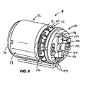
- FIG. 5 is an assembled, rear perspective view of the electric motor of FIG. 1 .
- FIG. 6 is an exploded, rear perspective view of a brush assembly of the electric motor of FIG. 1 .
- FIGS. 1 and 2 illustrate a battery-operated power tool 10 including a housing 14, a "hybrid” can-type/open frame electric motor 18 supported within the housing 14, and an output (e.g., a chuck assembly 22) drivably coupled to the motor 18 through an intermediate gear train or transmission 26 (see FIGS. 3 and 4 ).
- the tool housing 14 is formed of two interconnected housing shells 30, 34. Alternatively, the tool housing 14 may be formed using more than two shells 30, 34.
- the motor 18 is shown and described in connection with the power tool 10 (i.e., a hand-held drill), it should be understood that the motor 18 may be used with other battery-operated tools or corded tools. As another alternative, the motor 18 may be used with other products or devices besides power tools.
- the motor 18 includes a motor housing 42 and an armature 46 supported for rotation within the motor housing 42.
- opposed permanent magnets 50 are coupled to an sinner surface 54 of the motor housing 42 (using adhesives, etc.) and arranged such that the inwardly-facing poles of the magnets 50 are different from each other (i.e., one of the magnets 50 has an inwardly-facing "north" pole, while the other magnet 50 has an inwardly-facing "south” pole).
- a flux ring 58 is disposed about the motor housing 42 to focus the magnetic field generated by the magnets 50 within the interior of the motor housing 42.
- the armature 46 includes a shaft 62 and a plurality of coils or windings 66 couplet to the shaft 62 for co-mtation with the shaft 62.
- an electrical current is passed through each of the windings 66 in a direction substantially normal to the flux lines of the magnetic field generated by the permanent magnets 50, thereby imparting a torque on the armature 46.
- the direction of the electrical current through the windings 66 is switched during rotation of the armature 46 by a brush assembly 134 and commutator 154 (described in greater detail below), thereby resulting in a substantially continuous application of torque on the armature 46.
- the motor 18 is operable as a permanent magnet motor.
- electromagnets may be substituted for the permanent magnets 50 on the motor housing 42.
- the motor housing 42 includes a first end 70 having a face plate 74 and an open second end 78 (see FIG. 2 ).
- the face plate 74 includes an aperture 82 coaxial with a longitudinal axis 86 of the motor 18 in which a bearing 90 (e.g., a ball bearing, a bushing or sleeve bearing, etc.) is received (e.g., using an interference or press-fit, etc.).
- the face plate 74 also includes a plurality of mounting apertures 94 spaced from the longitudinal axis 86. As is discussed in greater detail below, the mounting apertures 94 facilitate alignment and interconnection of the motor 18 with other components of the power tool 10 (e.g., the transmission 26).
- the mounting apertures 94 may be threaded to receive corresponding threaded fasteners to interconnect the motor 18 with the transmission 26.
- a first or front end 98 of the shaft 62 is rotatably supported by the bearing 90 in the face plate 74.
- the front end 98 of the shaft 62 may be secured to the bearing 90 using an interference or press-fit.
- the front end 98 of the shaft 62 may include a coupling or one or more features defined thereon (e.g., splines, a keyway, etc.) to facilitate interconnection with the transmission 26 of the power tool 10.
- each housing shell 30, 34 includes a mount or receptacle 110 in which the bearing 106 is at least partially received and supported (only one of which is shown in FIGS. 3 and 4 ).
- the bearing 106 is captured within the receptacles 110 when the housing shells 30, 34 are connected, thereby securing the bearing 106 in the tool housing 14.
- the receptacles 110, and therefore the bearing 106, are coaxial with the longitudinal axis 86 of the motor 18 to maintain the alignment of the armature 46 with the longitudinal axis 86.
- each of the tool housing shells 30, 34 includes a fastening boss 114 on either side of the receptacle 110.
- corresponding fasteners are received in the bosses 114 to secure the housing shells 30, 34 to each other.
- the bosses 114 may be positioned relatively close to the receptacle 110 in each of the shells 30, 34. Specifically, the bosses 114 may be spaced from each other by a dimension S that is less than an outer diameter D1 of the motor housing 42 (see FIGS. 1 and 4 ).
- a conventional drill using a can motor typically includes fastening bosses on either side of the can separated by a distance that is greater than the outer diameter of the can.
- the spacing between the fastening bosses 114 on either side of the bearing 106 may be reduced, thereby allowing the overall size of the rear of the tool housing 14 to be reduced.
- the motor 18 also includes a fan 118 coupled for co-rotation with the armature 46.
- the fan 118 is coupled to the shaft 62 between the plurality of windings 66 and the rear end 102 of the shaft 62 using a plurality of tabs 120 on the fan 118 that are received between adjacent windings 66 on the armature 46. Adhesive may be used to secure the fan 118 to the armature 46.
- the fan 118 remains located outside the motor housing 42 between the open end 78 of the motor housing 42 and the bearing 106.
- the size of the fan 118 is not limited by the size of the motor bousing 42 (specifically, the outer diameter D1 of the motor housing 42).
- the fan 118 includes a plurality of blades 122 having respective blade tips 126 that circumscribe an outer diameter D2 of the fan 118.
- the outer diameter D2 of the fan 118 is at least as large as the outer diameter D1 of the motor housing 42.
- the fan 118 may be sized such that its outer diameter D2 is greater than the outer diameter D1 of the motor housing 42.
- each of the housing shells 30, 34 includes a plurality of cooling or exhaust apertures 130 proximate the fan 118 when the power tool 10 is assembled.
- rotation of the fan 118 with the armature 46 generates an airflow through the motor 18 to cool or remove heat from the motor 18.
- the heated airflow is subsequently exhausted through the apertures 130 in the tool housing 14.
- the power tool 10 further includes a brush assembly 134 supported by the power tool housing 14 and positioned outside the motor housing 42 between the open end 78 of the motor housing 42 and the rear end 102 of the shaft 62 (see FIGS. 3 and 4 ).
- the brush assembly 134 includes a holder 138 supported directly by the power tool housing 14 and a plurality of brushes 142 supported by the holder 138.
- the holder 138 defines an outer diameter D3 that is at least as large as the outer diameter D1 of the motor housing 42.
- the holder 138 maybe sized such that its outer diameter D3 is approximately equal to, greater than, or less than the outer diameter D1 of the motor housing 42.
- the brush holder 138 acts as a baffle to redirect the airflow generated by the fan 118 outside the tool housing 14 through the ventilation ports or cooling apertures 130 in the tool housing 14 (see FIGS. 1 and 2 ).
- each of the brushes 142 includes a contact pad 150 for slidably engaging the commutator 154 on the armature 46, which is responsible for reversing the direction of current flow through the windings 66 during operation of the motor 18.
- Each of the brushes 142 also includes an electrical lead 158 to electrically connect to a power source (e.g., a battery 162 of the power tool 10, etc.). As shown in FIGS. 5 and 6 , the electrical leads 158 initially extend from the brush holder 138 in a direction substantially normal to the longitudinal axis 86 of the motor 18.
- the electrical leads 158 extend downwardly from the holder 138, and then extend in a direction parallel to the axis 86 toward a trigger switch 166 of the power tool 10 (see FIG. 4 ).
- a conventional drill using a can motor typically includes a brush assembly positioned inside the can and electrical leads extending from the rear of the can in a direction substantially parallel with the longitudinal axis of the can motor before being redirected forwardly toward the trigger switch of the drill.
- the electrical leads 158 need not be redirected in this manner, thereby allowing the overall size (i.e., length) of the rear of the tool housing 14 to be reduced to provide a more compact power tool 10. Reducing the overall size of the power tool 10, in turn, would allow the operator to more comfortably use the power tool 10 over a longer period of time and reduce premature operator fatigue.
- the motor 18 achieves the benefits of a can motor and an open frame motor while substantially eliminating the drawbacks or disadvantages associated with each of the can motor and the open frame motor.
- the front portion 170 of the motor 18 including the motor housing 42 and face plate 74 facilitates alignment of the motor 18 with the chuck assembly 22 and the transmission 26 without requiring close or tight tolerances on the tool housing 14 to directly attach the magnets 50 or the front end 98 of the armature shaft 62 directly to the power tool housing 14, which is otherwise necessary with a conventional open frame motor.
- incorporating the motor housing 42 with the front portion 170 of the motor 18 obviates the need for a rolled flux ring arrangement, which is otherwise utilized with a conventional open frame motor.
- the rear portion 174 of the motor 18 including the fan 118 and the brush assembly 134 maybe sized without being constrained or limited by the size of the motor housing 42.
- the fan 118 may be sized having an outer diameter D2 approximately equal to or greater than the outer diameter D1 of the motor housing 42 to increase the cooling airflow through the motor 18, thereby enhancing the overall efficiency of the motor.
- the electrical leads 158 of the brushes 142 may extend from the holder 138 in a direction substantially normal to the longitudinal axis 86 of the motor 18, thereby reducing the overall size (i.e., length) of the rear of the tool housing 14. Reducing the overall size of the power tool 10, in turn, would allow the operator to more comfortably use the power tool 10 over a longer period of time and reduce premature operator fatigue.
- positioning the bearing 106 outside the motor housing 42 allows the spacing between the fastening bosses 114 on either side of the bearing 106 to be reduced, thereby allowing the overall size (i.e., diameter) of the rear of the tool housing 14 to be reduced to provide a more compact power tool 10.
- Directly supporting the bearing 106 with the tool housing 14 also eliminates the necessity of a commutator bearing plate, which is otherwise required in conventional can motors. The elimination of the commutator bearing plate yields an increased airflow past the motor 18 and reduces the amount of material used in the motor 18, and therefore the weight and cost of the power tool 10.
- An electric motor for use with a power tool may include a power tool housing, the power tool housing including a first portion and a second portion, the electric motor comprising:
- the electric motor may further comprises a fan coupled for co-rotation with the armature, wherein the fan is positioned outside of the motor housing between the open second end of the motor housing and the second end of the armature.
- the fan may include a plurality of blades having respective blade tips that circumscribe an outer diameter of the fan, and wherein the outer diameter of the fan is at least as large as an outer diameter of the motor housing.
- the electric motor may further comprises a brush assembly supportable by the power tool housing and positioned outside the motor housing between the open second end of the motor housing and the second end of the armature.
- the electric motor may further comprises a fan coupled for co-rotation with the armature, wherein the fan is positioned outside the motor housing between the open second end of the motor housing and the brush assembly.
- the brush assembly may include:
- the armature may define a longitudinal axis, and wherein the electrical lead of the at least one brush extends from the brush holder in a direction substantially normal to the longitudinal axis.
- An outer diameter of the brush holder may be at least as large as an outer diameter of the motor housing.
- the first bearing may be one of a ball bearing and a sleeve bearing.
- the second beating may be one of a ball bearing and a sleeve bearing.
- a power tool may comprise:
- the power tool may further comprise a fan coupled for co-rotation with the armature, wherein the fan is positioned outside of the motor housing between the open second end of the motor housing and the second end of the armature.
- the fan may include a plurality of blades having respective blade tips that circumscribe an outer diameter of the fan, and wherein the outer diameter of the fan is at least as large as an outer diameter of the motor housing.
- the power tool may further comprise a brush assembly supported by the power tool hosing and positioned outside of the motor housing between the open second end of the motor housing and the second end of the armature.
- the power tool may further comprise further comprising a fan coupled for co-rotation with the armature, wherein the fan is positioned outside of the motor housing between the open second end of the motor housing and the brush assembly.
- the brush assembly may include:
- the armature may define a longitudinal axis, and wherein the electrical lead of the at least one brush extends from the brush holder in a direction substantially normal to the longitudinal axis.
- An outer diameter of the brush holder may be at least as large as an outer diameter of the motor housing.
- the first bearing may be one of a ball bearing and a sleeve bearing.
- the second bearing may be one of a ball bearing and a sleeve bearing.
Landscapes
- Engineering & Computer Science (AREA)
- Power Engineering (AREA)
- Mechanical Engineering (AREA)
- Connection Of Motors, Electrical Generators, Mechanical Devices, And The Like (AREA)
- Motor Or Generator Frames (AREA)
- Iron Core Of Rotating Electric Machines (AREA)
Abstract
Description
- The present invention relates to power tools, and more particularly to electric motors for use with power tools.
- In the field of power tools, and specifically in the field of battery-powered hand tools such as drills, two types of motors are known and used - a self-contained "can-type" or "can" motor and an "open frame" motor.
- Can motors typically include a housing in the form of a cylindrical can in which essentially all of the components of the motor are received, including the armature, magnets, brushes, motor housing, fan, and bearings. Most DC battery-powered tools incorporate a can motor to drive the power tool output due to the simplicity of assembly and low cost of can motors. Can motors are often preassembled, thereby simplifying assembly of the can motors in power tools. Because the motor components are disposed within a can, a can motor can be operated without the motor being mounted in a product. Typically, can motors include several mounting holes on the front of the can to facilitate attachment to a product or gear train. Such mounting holes on the front of the can simplifies alignment of the motor shaft with the product or gear train with which the can motor is used.
- Though assembly of can motors into a power tool is oftentimes fairly simple and cost efficient, the power tool housing must be sized to accommodate the can. For example, screw bosses in the power tool housing must be located outside of the outer periphery of the can, which often creates dead or unused space between the tool housing and the motor, often imposing limitations on the size of the power tool. The larger the power tool, the more difficult it is for some users to operate. For example, increasing the length of a drill also increases the distance of the drill's center of mass from the operator's hand, requiring more work from the operator to maneuver the drill, potentially leading to premature fatigue.
- Can motors also often restrict the dimensions of the fan used to cool the motor because the outer diameter of the fan is limited by the inner diameter of the can. In addition, air circulation within the can is oftentimes limited. The combination of the limited fan size and limited air circulation in the can often decreases the cooling capability of the can motor.
- Open frame motors are often used in power tools, but typically at a greater cost and greater difficulty of manufacturing compared to can motors. Open frame motors typically include an armature and a permanent magnet rolled flux ring field. Open frame motors must be installed within a power tool prior to their operation because the individual components of the motor are not contained within a common housing inside the tool housing as in a can motor. Open frame motors typically contain fewer components than can motors (specifically, the can or can housing is omitted). The components of an open frame motor are often installed in tool housings individually, often leading to difficulty associated with controlling the component centerline relationships and attachment of the bearings, gear train, and permanent magnet field to the power tool housing. As a result, tool housings incorporating open frame motors must often be manufactured using closer or tighter tolerances.
- The present invention provides, in one aspect, an electric motor for use with a power tool including a housing. The electric motor includes a motor housing having a first end and an open second end, a first bearing coupled to the first end of the motor housing, a plurality of magnets coupled to the motor housing, and an armature having a first end and a second end. The first end of the armature is rotatably supported by the first bearing. The second end of the armature protrudes from the open second end of the motor housing without being supported by the open second end of the motor housing. The electric motor also includes a second bearing coupled to the second end of the armature. The motor housing is supportable by a first portion of the power tool housing. The second bearing is supportable by a second portion of the power tool housing.
- The present invention provides, in another aspect, a power tool including a power tool housing and a motor housing supported by a first portion of the power tool housing. The motor housing has a first end and an open second end. The power tool also includes a first bearing coupled to the first end of the motor housing, a plurality of magnets coupled to the motor housing, and an armature having a first end and a second end. The first end of the armature is rotatably supported by the first bearing. The second end of the armature protrudes from the open second end of the motor housing without being supported by the open second end of the motor housing. The power tool further includes a second bearing coupled to the second end of the armature and supported by a second portion of the power tool housing.
- Further aspects of the invention are provided in the appended claims.
- Other features and aspects of the invention will become apparent by consideration of the following detailed description and accompanying drawings.
-
FIG. 1 is an exploded perspective view of a power tool and an electric motor of the present invention. -
FIG. 2 is a reverse, exploded perspective view of the power tool and electric motor ofFIG. 1 . -
FIG. 3 is an assembled, rear perspective view of the power tool ofFIG. 1 , illustrating a portion of the power tool housing cut away to expose the electric motor. -
FIG. 4 is a side view of the power tool ofFIG. 3 . -
FIG. 5 is an assembled, rear perspective view of the electric motor ofFIG. 1 . -
FIG. 6 is an exploded, rear perspective view of a brush assembly of the electric motor ofFIG. 1 . - Before any embodiments of the invention are explained in detail, it is to be understood that the invention is not limited in its application to the details of construction and the arrangement of components set forth in the following description or illustrated in the following drawings. The invention is capable of other embodiments and of being practiced or of being carried out in various ways. Also, it is to be understood that the phraseology and terminology used herein is for the purpose of description and should not be regarded as limiting.
-
FIGS. 1 and2 illustrate a battery-operatedpower tool 10 including ahousing 14, a "hybrid" can-type/open frameelectric motor 18 supported within thehousing 14, and an output (e.g., a chuck assembly 22) drivably coupled to themotor 18 through an intermediate gear train or transmission 26 (seeFIGS. 3 and4 ). Thetool housing 14 is formed of two interconnectedhousing shells tool housing 14 may be formed using more than twoshells motor 18 is shown and described in connection with the power tool 10 (i.e., a hand-held drill), it should be understood that themotor 18 may be used with other battery-operated tools or corded tools. As another alternative, themotor 18 may be used with other products or devices besides power tools. - With reference to
FIGS. 1 and2 , themotor 18 includes amotor housing 42 and anarmature 46 supported for rotation within themotor housing 42. With reference toFIG. 2 , opposed permanent magnets 50 are coupled to ansinner surface 54 of the motor housing 42 (using adhesives, etc.) and arranged such that the inwardly-facing poles of the magnets 50 are different from each other (i.e., one of the magnets 50 has an inwardly-facing "north" pole, while the other magnet 50 has an inwardly-facing "south" pole). Aflux ring 58 is disposed about themotor housing 42 to focus the magnetic field generated by the magnets 50 within the interior of themotor housing 42. - The
armature 46 includes ashaft 62 and a plurality of coils orwindings 66 couplet to theshaft 62 for co-mtation with theshaft 62. In operation of themotor 18, an electrical current is passed through each of thewindings 66 in a direction substantially normal to the flux lines of the magnetic field generated by the permanent magnets 50, thereby imparting a torque on thearmature 46. The direction of the electrical current through thewindings 66 is switched during rotation of thearmature 46 by abrush assembly 134 and commutator 154 (described in greater detail below), thereby resulting in a substantially continuous application of torque on thearmature 46. In this manner, themotor 18 is operable as a permanent magnet motor. Alternatively, electromagnets may be substituted for the permanent magnets 50 on themotor housing 42. - With reference to
FIG. 1 , themotor housing 42 includes afirst end 70 having a face plate 74 and an open second end 78 (seeFIG. 2 ). With reference toFIG. 1 , the face plate 74 includes an aperture 82 coaxial with a longitudinal axis 86 of themotor 18 in which a bearing 90 (e.g., a ball bearing, a bushing or sleeve bearing, etc.) is received (e.g., using an interference or press-fit, etc.). The face plate 74 also includes a plurality of mounting apertures 94 spaced from the longitudinal axis 86. As is discussed in greater detail below, the mounting apertures 94 facilitate alignment and interconnection of themotor 18 with other components of the power tool 10 (e.g., the transmission 26). The mounting apertures 94 may be threaded to receive corresponding threaded fasteners to interconnect themotor 18 with thetransmission 26. - With reference to
FIG. 1 , a first orfront end 98 of theshaft 62 is rotatably supported by the bearing 90 in the face plate 74. Thefront end 98 of theshaft 62 may be secured to the bearing 90 using an interference or press-fit. Although not shown in the drawings, thefront end 98 of theshaft 62 may include a coupling or one or more features defined thereon (e.g., splines, a keyway, etc.) to facilitate interconnection with thetransmission 26 of thepower tool 10. - With reference to
FIG. 4 , the entire length of each of thewindings 66 is enclosed within themotor housing 42, while a second orrear end 102 of theshaft 62 protrudes from theopen md 78 of themotor housing 42 without being supported by theopen end 78 of themotor housing 42. Therear end 102 of theshaft 62 is rotatably supported by a bearing 106 (e.g., a ball bearing, a bushing or sleeve bearing, etc.) directly supported by the tool housing 14 (see alsoFIGS. 1 and2 ). Specifically, eachhousing shell receptacle 110 in which thebearing 106 is at least partially received and supported (only one of which is shown inFIGS. 3 and4 ). Thebearing 106 is captured within thereceptacles 110 when thehousing shells bearing 106 in thetool housing 14. Thereceptacles 110, and therefore thebearing 106, are coaxial with the longitudinal axis 86 of themotor 18 to maintain the alignment of thearmature 46 with the longitudinal axis 86. - With continued reference to
FIGS. 3 and4 , each of thetool housing shells fastening boss 114 on either side of thereceptacle 110. When thehousing shells bosses 114 to secure thehousing shells bearing 106 is positioned outside themotor housing 42, thebosses 114 may be positioned relatively close to thereceptacle 110 in each of theshells bosses 114 may be spaced from each other by a dimension S that is less than an outer diameter D1 of the motor housing 42 (seeFIGS. 1 and4 ). In contrast, a conventional drill using a can motor typically includes fastening bosses on either side of the can separated by a distance that is greater than the outer diameter of the can. As such, by positioning thebearing 106 outside themotor housing 42, the spacing between thefastening bosses 114 on either side of thebearing 106 may be reduced, thereby allowing the overall size of the rear of thetool housing 14 to be reduced. - With reference to
FIGS. 1 and2 , themotor 18 also includes afan 118 coupled for co-rotation with thearmature 46. Specifically, thefan 118 is coupled to theshaft 62 between the plurality ofwindings 66 and therear end 102 of theshaft 62 using a plurality oftabs 120 on thefan 118 that are received betweenadjacent windings 66 on thearmature 46. Adhesive may be used to secure thefan 118 to thearmature 46. When thearmature 46 is inserted into themotor housing 42, thefan 118 remains located outside themotor housing 42 between theopen end 78 of themotor housing 42 and thebearing 106. By positioning thefan 118 outside themotor housing 42, the size of thefan 118 is not limited by the size of the motor bousing 42 (specifically, the outer diameter D1 of the motor housing 42). With reference toFIG. 1 , thefan 118 includes a plurality ofblades 122 havingrespective blade tips 126 that circumscribe an outer diameter D2 of thefan 118. As shown inFIGS. 1 and4 , the outer diameter D2 of thefan 118 is at least as large as the outer diameter D1 of themotor housing 42. Alternatively, thefan 118 may be sized such that its outer diameter D2 is greater than the outer diameter D1 of themotor housing 42. With reference toFIG. 1 , each of thehousing shells exhaust apertures 130 proximate thefan 118 when thepower tool 10 is assembled. In operation of thepower tool 10, rotation of thefan 118 with thearmature 46 generates an airflow through themotor 18 to cool or remove heat from themotor 18. The heated airflow is subsequently exhausted through theapertures 130 in thetool housing 14. - The
power tool 10 further includes abrush assembly 134 supported by thepower tool housing 14 and positioned outside themotor housing 42 between theopen end 78 of themotor housing 42 and therear end 102 of the shaft 62 (seeFIGS. 3 and4 ). As shown inFIG. 6 , thebrush assembly 134 includes aholder 138 supported directly by thepower tool housing 14 and a plurality ofbrushes 142 supported by theholder 138. With reference toFIG. 1 , theholder 138 defines an outer diameter D3 that is at least as large as the outer diameter D1 of themotor housing 42. Alternatively, theholder 138 maybe sized such that its outer diameter D3 is approximately equal to, greater than, or less than the outer diameter D1 of themotor housing 42. In addition to supporting thebrushes 142, thebrush holder 138 acts as a baffle to redirect the airflow generated by thefan 118 outside thetool housing 14 through the ventilation ports or coolingapertures 130 in the tool housing 14 (seeFIGS. 1 and2 ). - With reference to
FIG. 6 , each of thebrushes 142 includes acontact pad 150 for slidably engaging thecommutator 154 on thearmature 46, which is responsible for reversing the direction of current flow through thewindings 66 during operation of themotor 18. Each of thebrushes 142 also includes anelectrical lead 158 to electrically connect to a power source (e.g., abattery 162 of thepower tool 10, etc.). As shown inFIGS. 5 and6 , theelectrical leads 158 initially extend from thebrush holder 138 in a direction substantially normal to the longitudinal axis 86 of themotor 18. Specifically, theelectrical leads 158 extend downwardly from theholder 138, and then extend in a direction parallel to the axis 86 toward atrigger switch 166 of the power tool 10 (seeFIG. 4 ). In contrast, a conventional drill using a can motor typically includes a brush assembly positioned inside the can and electrical leads extending from the rear of the can in a direction substantially parallel with the longitudinal axis of the can motor before being redirected forwardly toward the trigger switch of the drill. As such, by positioning thebrush assembly 134 outside themotor housing 42, theelectrical leads 158 need not be redirected in this manner, thereby allowing the overall size (i.e., length) of the rear of thetool housing 14 to be reduced to provide a morecompact power tool 10. Reducing the overall size of thepower tool 10, in turn, would allow the operator to more comfortably use thepower tool 10 over a longer period of time and reduce premature operator fatigue. - With reference to
FIG. 4 , themotor 18 achieves the benefits of a can motor and an open frame motor while substantially eliminating the drawbacks or disadvantages associated with each of the can motor and the open frame motor. Specifically, the front portion 170 of themotor 18 including themotor housing 42 and face plate 74 facilitates alignment of themotor 18 with thechuck assembly 22 and thetransmission 26 without requiring close or tight tolerances on thetool housing 14 to directly attach the magnets 50 or thefront end 98 of thearmature shaft 62 directly to thepower tool housing 14, which is otherwise necessary with a conventional open frame motor. In addition, incorporating themotor housing 42 with the front portion 170 of themotor 18 obviates the need for a rolled flux ring arrangement, which is otherwise utilized with a conventional open frame motor. - Also, the rear portion 174 of the
motor 18 including thefan 118 and thebrush assembly 134 maybe sized without being constrained or limited by the size of themotor housing 42. As a result, thefan 118 may be sized having an outer diameter D2 approximately equal to or greater than the outer diameter D1 of themotor housing 42 to increase the cooling airflow through themotor 18, thereby enhancing the overall efficiency of the motor. In addition, theelectrical leads 158 of thebrushes 142 may extend from theholder 138 in a direction substantially normal to the longitudinal axis 86 of themotor 18, thereby reducing the overall size (i.e., length) of the rear of thetool housing 14. Reducing the overall size of thepower tool 10, in turn, would allow the operator to more comfortably use thepower tool 10 over a longer period of time and reduce premature operator fatigue. - Further, positioning the
bearing 106 outside themotor housing 42 allows the spacing between thefastening bosses 114 on either side of thebearing 106 to be reduced, thereby allowing the overall size (i.e., diameter) of the rear of thetool housing 14 to be reduced to provide a morecompact power tool 10. Directly supporting the bearing 106 with thetool housing 14 also eliminates the necessity of a commutator bearing plate, which is otherwise required in conventional can motors. The elimination of the commutator bearing plate yields an increased airflow past themotor 18 and reduces the amount of material used in themotor 18, and therefore the weight and cost of thepower tool 10. - One or more preferred embodiments of the invention have been describe above, however, these are not meant to limit the scope or use or functionality of the invention, some, but not all, aspects of which are summarized in the following paragraphs.
- An electric motor for use with a power tool may include a power tool housing, the power tool housing including a first portion and a second portion, the electric motor comprising:
- a motor housing having a first end and an open second end;
- a first bearing coupled to the first end of the motor housing;
- a plurality of magnets coupled to the motor housing;
- an armature having a first end and a second end, the first end of the armature being rotatably supported by the first bearing, the second end of the armature protruding from the open second end of the motor housing without being supported by the open second end of the motor housing; and
- a second bearing coupled to the second end of the armature;
- The electric motor may further comprises a fan coupled for co-rotation with the armature, wherein the fan is positioned outside of the motor housing between the open second end of the motor housing and the second end of the armature.
- The fan may include a plurality of blades having respective blade tips that circumscribe an outer diameter of the fan, and wherein the outer diameter of the fan is at least as large as an outer diameter of the motor housing.
- The electric motor may further comprises a brush assembly supportable by the power tool housing and positioned outside the motor housing between the open second end of the motor housing and the second end of the armature.
- The electric motor may further comprises a fan coupled for co-rotation with the armature, wherein the fan is positioned outside the motor housing between the open second end of the motor housing and the brush assembly.
- The brush assembly may include:
- a brush holder;
- at least one brush supported by the brush holder; and
- an electrical lead extending from the at least one brush.
- The armature may define a longitudinal axis, and wherein the electrical lead of the at least one brush extends from the brush holder in a direction substantially normal to the longitudinal axis.
- An outer diameter of the brush holder may be at least as large as an outer diameter of the motor housing.
- The first bearing may be one of a ball bearing and a sleeve bearing.
- The second beating may be one of a ball bearing and a sleeve bearing.
- A power tool may comprise:
- a power tool housing;
- a motor housing supported by a first portion of the power tool housing, the motor housing having a first end and an open second end;
- a first bearing coupled to the first end of the motor housing;
- a plurality of magnets coupled to the motor housing;
- an armature having a first end and a second end, the first end of the armature being rotatably supported by the first bearing, the second end of the armature protruding from the open second end of the motor housing without being supported by the open second end of the motor housing; and
- a second bearing coupled to the second end of the armature and supported by a second portion of the power tool hosing
- The power tool may further comprise a fan coupled for co-rotation with the armature, wherein the fan is positioned outside of the motor housing between the open second end of the motor housing and the second end of the armature.
- The fan may include a plurality of blades having respective blade tips that circumscribe an outer diameter of the fan, and wherein the outer diameter of the fan is at least as large as an outer diameter of the motor housing.
- The power tool may further comprise a brush assembly supported by the power tool hosing and positioned outside of the motor housing between the open second end of the motor housing and the second end of the armature.
- The power tool may further comprise further comprising a fan coupled for co-rotation with the armature, wherein the fan is positioned outside of the motor housing between the open second end of the motor housing and the brush assembly.
- The brush assembly may include:
- a brush holder;
- at least one brash supported by the brush bolder; and
- an electrical lead extending from the at least one brush.
- The armature may define a longitudinal axis, and wherein the electrical lead of the at least one brush extends from the brush holder in a direction substantially normal to the longitudinal axis.
- An outer diameter of the brush holder may be at least as large as an outer diameter of the motor housing.
- The first bearing may be one of a ball bearing and a sleeve bearing.
- The second bearing may be one of a ball bearing and a sleeve bearing.
Claims (15)
- An electric motor for use with a power tool including a power tool housing, the power tool housing including a first portion and a second portion, the electric motor comprising:a motor housing having a first end and an open second end;a first bearing coupled to the first end of the motor housing;a plurality of magnets coupled to the motor housing;an armature having a first end and a second end, the first end of the armature being rotatably supported by the first bearing, the second end of the armature protruding from the open second end of the motor housing without being supported by the open second end of the motor housing; anda second bearing coupled to the second end of the armature;wherein the motor housing is supportable by the first portion of the power tool housing, and wherein the second bearing is supportable by the second portion of the power tool housing.
- The electric motor of claim 1, further comprising a fan coupled for co-rotation with the armature, wherein the fan is positioned outside of the motor housing between the open second end of the motor housing and the second end of the armature.
- The electric motor of claims 1 or 2, wherein the fan includes a plurality of blades having respective blade tips that circumscribe an outer diameter of the fan, and wherein the outer diameter of the fan is at least as large as an outer diameter of the motor housing.
- The electric motor of any preceding claim, further comprising a brush assembly supportable by the power tool housing and positioned outside the motor housing between the open second end of the motor housing and the second end of the armature.
- The electric motor of claim 5, further comprising a fan coupled for co-rotation with the armature, wherein the fan is positioned outside the motor housing between the open second end of the motor housing and the brush assembly.
- The electric motor of claims 4 or 5, wherein the brush assembly includes:a brush holder;at least one brush supported by the brush holder; andan electrical lead extending from the at least one brush.
- The electric motor of claim 6, wherein the armature defines a longitudinal axis, and wherein the electrical lead of the at least one brush extends from the brush holder in a direction substantially normal to the longitudinal axis.
- The electric motor of claim 6, wherein an outer diameter of the brush holder is at least as large as an outer diameter of the motor housing.
- A power tool comprising:a power tool housing;a motor housing supported by a first portion of the power tol housing, the motor housing having a first end end an open second end;a first bearing coupled to the first end of the motor housing;a plurality of magnets coupled to the motor housing;an armature having a first end and a second end, the first end of the armature being rotatably supported by the first bearing, the second end of the armature protruding from the open second end of the motor housing without being supported by the open second end of the motor housing; anda second bearing coupled to the second end of the armature and supported by a second portion of the power tool housing.
- The power tool of claim 9, further comprising a fan coupled for co-rotation with the armature, wherein the fan is positioned outside of the motor housing between the open second end of the motor hosing and the second end of the armature.
- The power tool of claims 9 or 10, wherein the fan includes a plurality of blades having respective blade tips that circumscribe an outer diameter of the fan, and wherein the outer diameter of the fan is at least as large as an outer diameter of the motor housing.
- The power tool of any one of claims 9 to 11, further comprising a brush assembly supported by the power tool housing and positioned outside of the motor housing between the open second end of the motor housing and the second end of the armature.
- The power tool of claim 12, further comprising a fan coupled for co-rotation with the armature, wherein the fan is positioned outside of the motor housing between the open second end of the motor housing and the brush assembly.
- The power tool of claims 12 or 13, wherein the brush assembly includes:a brush holder;at least one brush supported by the brush holder; andan electrical lead extending from the at least one brush.
- The power tool of claim 14, wherein the armature defines a longitudinal axis, and wherein the electrical lead of the at least one brush extends from the brush holder in a direction substantially normal to the longitudinal axis.
Applications Claiming Priority (2)
| Application Number | Priority Date | Filing Date | Title |
|---|---|---|---|
| US7580508P | 2008-06-26 | 2008-06-26 | |
| US12/417,777 US8508084B2 (en) | 2008-06-26 | 2009-04-03 | Power tool including hybrid electric motor design |
Publications (3)
| Publication Number | Publication Date |
|---|---|
| EP2139095A2 true EP2139095A2 (en) | 2009-12-30 |
| EP2139095A3 EP2139095A3 (en) | 2012-05-02 |
| EP2139095B1 EP2139095B1 (en) | 2015-10-28 |
Family
ID=40996599
Family Applications (1)
| Application Number | Title | Priority Date | Filing Date |
|---|---|---|---|
| EP09251644.2A Active EP2139095B1 (en) | 2008-06-26 | 2009-06-25 | Power tool including hybrid electric motor design |
Country Status (2)
| Country | Link |
|---|---|
| US (1) | US8508084B2 (en) |
| EP (1) | EP2139095B1 (en) |
Cited By (1)
| Publication number | Priority date | Publication date | Assignee | Title |
|---|---|---|---|---|
| EP4436753A2 (en) * | 2021-11-23 | 2024-10-02 | Hilti Aktiengesellschaft | Hand-held power tool |
Families Citing this family (18)
| Publication number | Priority date | Publication date | Assignee | Title |
|---|---|---|---|---|
| DE102008059599A1 (en) * | 2008-11-28 | 2010-06-02 | Aeg Electric Tools Gmbh | power tool |
| CN101651396B (en) * | 2009-09-23 | 2012-05-23 | 杭州天铭机电工具有限公司 | Direct current motor |
| DE102010003583A1 (en) * | 2010-04-01 | 2011-10-06 | Robert Bosch Gmbh | Hand-held power tool |
| US9450472B2 (en) | 2010-06-14 | 2016-09-20 | Black & Decker, Inc. | Rotor assembly for brushless motor for a power tool |
| EP2465647A3 (en) * | 2010-12-20 | 2013-01-16 | HILTI Aktiengesellschaft | Hand tool machine with air circulation element |
| JP5725354B2 (en) * | 2011-08-19 | 2015-05-27 | 日立工機株式会社 | Electric tool |
| WO2014036003A1 (en) * | 2012-08-27 | 2014-03-06 | Ingersoll-Rand Company | Power tool housing construction |
| US20140091648A1 (en) * | 2012-10-02 | 2014-04-03 | Makita Corporation | Electric power tool |
| US20140124231A1 (en) | 2012-11-06 | 2014-05-08 | Milwaukee Electric Tool Corporation | Electric motor for a power tool |
| US10432045B2 (en) * | 2012-11-06 | 2019-10-01 | Milwaukee Electric Tool Corporation | Electric motor for a power tool |
| US8561302B1 (en) * | 2013-02-03 | 2013-10-22 | Frank August Barcatta | Electrically driven linear cutter |
| US10181767B2 (en) * | 2013-08-09 | 2019-01-15 | Black & Decker Inc. | Brush assembly with brush card mount with brush holders having base and main portion pieces |
| US9991770B2 (en) | 2013-08-09 | 2018-06-05 | Black & Decker Inc. | Spring post for brush card for a power tool |
| US9866078B2 (en) | 2014-01-29 | 2018-01-09 | Black & Decker Inc. | Brush assembly mount |
| GB201413008D0 (en) * | 2014-07-23 | 2014-09-03 | Black & Decker Inc | A range of power tools |
| CN107546885A (en) * | 2016-06-28 | 2018-01-05 | 德昌电机(深圳)有限公司 | Rotor, the manufacture method of rotor, motor and electric tool |
| EP3697575A4 (en) | 2017-10-20 | 2021-11-17 | Milwaukee Electric Tool Corporation | POWER TOOL BEARING RETAINER |
| US11545871B2 (en) | 2020-09-02 | 2023-01-03 | Snap-On Incorporated | Tool housing and motor exhaust management |
Family Cites Families (52)
| Publication number | Priority date | Publication date | Assignee | Title |
|---|---|---|---|---|
| US2082264A (en) | 1935-06-22 | 1937-06-01 | Scruggs Loyd | Electric motor |
| US2294713A (en) | 1940-03-23 | 1942-09-01 | Allover Mfg Co | Electric hair clipper |
| US2456571A (en) | 1947-09-13 | 1948-12-14 | Singer Mfg Co | Portable electric tool |
| DE1014211B (en) * | 1952-09-18 | 1957-08-22 | Bosch Gmbh Robert | Hand machine tool with an electric drive motor, which is housed in an insulated metallic outer housing |
| US3344291A (en) | 1964-11-23 | 1967-09-26 | Millers Falls Co | Double insulated hand tool |
| US3430084A (en) | 1966-07-06 | 1969-02-25 | Rockwell Mfg Co | Electric motor and brush assembly for a portable tool |
| DE1628045B2 (en) | 1967-01-13 | 1974-01-10 | Robert Bosch Gmbh, 7000 Stuttgart | Hammer device with a drive motor installed transversely to the direction of impact |
| US3430709A (en) * | 1967-10-02 | 1969-03-04 | Black & Decker Mfg Co | Motion transmission mechanism for impact tools |
| US3426227A (en) * | 1967-10-04 | 1969-02-04 | Black & Decker Mfg Co | Motor field mounting |
| US3651707A (en) * | 1970-07-22 | 1972-03-28 | Thor Power Tool Co | Portable power tool construction |
| US4342929A (en) | 1979-07-13 | 1982-08-03 | Black & Decker Inc. | Electric motor wherein low temperature polymeric housing supports heat dissipating portions through heat resisting polymeric bridging member |
| US4574471A (en) | 1983-03-31 | 1986-03-11 | Black & Decker Inc. | Methods of assembling components of an electric motor |
| DE3536464A1 (en) * | 1985-10-12 | 1987-04-16 | Licentia Gmbh | Electric tool having a drive motor which is mounted in a plastic housing |
| IT1223913B (en) | 1988-11-17 | 1990-09-29 | Magneti Marelli Spa | ALTERNATOR WITH FORCED VENTILATION PARTICULARLY FOR VEHICLES |
| US4979303A (en) | 1989-02-21 | 1990-12-25 | Han Xiaowen S | Self hair cutting device |
| DE4019894A1 (en) * | 1989-07-15 | 1991-04-11 | Ceka Elektrowerkzeuge Ag & Co | Hand held electric power tool with pistol grip handle - has motor and main weight concentrated in handle with short tool spindle for improved location and drive control via geared transmission |
| US5349785A (en) | 1992-11-30 | 1994-09-27 | Black & Decker Inc. | Motor support for orbital polisher |
| ES2194044T3 (en) * | 1994-07-26 | 2003-11-16 | Black & Decker Inc | MOTORIZED TOOL WITH MODULAR DRIVE SYSTEM AND MODULAR DRIVE SYSTEM ASSEMBLY METHOD. |
| JPH08140308A (en) | 1994-11-10 | 1996-05-31 | Mitsubishi Electric Corp | Vehicle charging generator |
| DE19521425B4 (en) * | 1995-06-14 | 2007-03-29 | Robert Bosch Gmbh | Hand tool with electric motor, and their electric motor with centering rings on the front sides of the pole tube |
| JP3622350B2 (en) | 1996-08-09 | 2005-02-23 | 株式会社デンソー | Rotating electric machine |
| JP3674270B2 (en) * | 1997-04-23 | 2005-07-20 | 松下電工株式会社 | Electric tool |
| JP2000116072A (en) | 1998-10-01 | 2000-04-21 | Makita Corp | Mounting structure for brush holder |
| DE19941620A1 (en) | 1999-09-01 | 2001-03-08 | Bosch Gmbh Robert | Hand tool |
| EP1100182A1 (en) | 1999-11-12 | 2001-05-16 | General Electric Company | Fan cooled electric motors with increased thermal dissipation |
| DE20000223U1 (en) | 2000-01-10 | 2001-05-23 | Robert Bosch Gmbh, 70469 Stuttgart | Angle grinder with electric drive |
| DE10063619B4 (en) | 2000-12-20 | 2010-02-18 | Trw Automotive Electronics & Components Gmbh & Co. Kg | Drive unit for blowers in vehicles |
| DE10065771A1 (en) | 2000-12-30 | 2002-07-04 | Bosch Gmbh Robert | Hand tool |
| US6903475B2 (en) * | 2001-02-23 | 2005-06-07 | Black & Decker Inc. | Stator assembly with an overmolding that secures magnets to a flux ring and the flux ring to a stator housing |
| JP3711877B2 (en) * | 2001-03-02 | 2005-11-02 | 日立工機株式会社 | Electric tool |
| GB0111535D0 (en) | 2001-05-11 | 2001-07-04 | Johnson Electric Sa | Gear motor for power tool |
| JP4164262B2 (en) | 2001-12-07 | 2008-10-15 | 日立工機株式会社 | Power tool and insulation method thereof |
| GB2385715A (en) | 2002-02-07 | 2003-08-27 | Johnson Electric Sa | Double Bladed Fan |
| GB2385017B (en) | 2002-02-08 | 2005-06-29 | Black & Decker Inc | Drilling and/or hammering tool |
| US6719541B2 (en) | 2002-04-30 | 2004-04-13 | Northland/Scott Fetzer Company | Fan assembly with application to vacuum cleaners |
| DE10242738A1 (en) | 2002-09-13 | 2005-01-20 | Robert Bosch Gmbh | Hand tool machine, in particular angle grinder |
| GB0229969D0 (en) * | 2002-12-21 | 2003-01-29 | Johnson Electric Sa | A motor and gearbox combination |
| US7063170B2 (en) * | 2003-02-26 | 2006-06-20 | Black & Decker Inc. | Flexible power tool motor pack and method of making the same |
| US7121445B2 (en) | 2003-04-22 | 2006-10-17 | Credo Technology Corporation | Power tool housing |
| DE10319460A1 (en) | 2003-04-29 | 2004-11-18 | Robert Bosch Gmbh | Electric hand machine tool with electric motor drive |
| JP4374909B2 (en) | 2003-05-27 | 2009-12-02 | パナソニック電工株式会社 | Brushless motor |
| JPWO2005101616A1 (en) | 2004-04-15 | 2008-03-06 | 株式会社ミツバ | Brushless motor |
| TWI326631B (en) | 2004-04-28 | 2010-07-01 | Sankyo Seisakusho Kk | Machine tool and detachable/attachable motor |
| JP4639061B2 (en) | 2004-07-29 | 2011-02-23 | 株式会社マキタ | Electric tool |
| JP4487836B2 (en) | 2005-04-20 | 2010-06-23 | 日立工機株式会社 | Electric tool |
| JP2007028743A (en) * | 2005-07-14 | 2007-02-01 | Hitachi Koki Co Ltd | Commutator motor rotor and electric tool including the same |
| CN2858198Y (en) | 2005-07-27 | 2007-01-17 | 苏州宝时得电动工具有限公司 | Electromotion tool |
| JP4692288B2 (en) * | 2006-01-11 | 2011-06-01 | 日立工機株式会社 | Electric tool and assembling method thereof |
| JP4797779B2 (en) | 2006-04-27 | 2011-10-19 | 株式会社デンソー | AC generator for vehicles |
| JP4756474B2 (en) | 2006-07-20 | 2011-08-24 | 日立工機株式会社 | Electric tool |
| SE531738C2 (en) | 2006-09-01 | 2009-07-28 | Husqvarna Ab | Drilling machine |
| DE102006059336A1 (en) * | 2006-12-15 | 2008-06-19 | A & M Electric Tools Gmbh | Handheld electrical machine tool comprises an electrical drive motor with a stator having a magnet arrangement fixed in an oscillating manner in a housing to form the damping body of an oscillation damper |
-
2009
- 2009-04-03 US US12/417,777 patent/US8508084B2/en active Active
- 2009-06-25 EP EP09251644.2A patent/EP2139095B1/en active Active
Cited By (1)
| Publication number | Priority date | Publication date | Assignee | Title |
|---|---|---|---|---|
| EP4436753A2 (en) * | 2021-11-23 | 2024-10-02 | Hilti Aktiengesellschaft | Hand-held power tool |
Also Published As
| Publication number | Publication date |
|---|---|
| US8508084B2 (en) | 2013-08-13 |
| EP2139095B1 (en) | 2015-10-28 |
| US20090322166A1 (en) | 2009-12-31 |
| EP2139095A3 (en) | 2012-05-02 |
Similar Documents
| Publication | Publication Date | Title |
|---|---|---|
| US8508084B2 (en) | Power tool including hybrid electric motor design | |
| US11646626B2 (en) | Brushless motor for a power tool | |
| JP3600860B2 (en) | Roller with built-in motor and unit for roller with built-in motor | |
| EP1715565B1 (en) | Power tool | |
| EP2158063B1 (en) | Power tool | |
| US8816544B2 (en) | Power tool with a housing including a guide portion for guiding cooling air along a switching circuit board | |
| US8567521B2 (en) | Power tool | |
| JP5454777B2 (en) | Electric tool | |
| US20120313464A1 (en) | Electric tools | |
| JP2010173042A (en) | Power tool | |
| US20150041167A1 (en) | Electric working machine | |
| CN220022577U (en) | Power tool and electric motor assembly | |
| EP1621293A2 (en) | Power tool | |
| CN215990384U (en) | electrical tools | |
| EP4113795A2 (en) | Motor rotor with sleeve for retention of magnet ring | |
| EP4102687A2 (en) | Overmolded rotor structure | |
| CN101656454A (en) | Power tool including hybrid electric motor design | |
| GB2480137A (en) | Suppression of commutator-sourced interference in an electric tool | |
| JP5024609B2 (en) | Electric tool | |
| EP3603894B1 (en) | Power tool | |
| JP7791996B2 (en) | manual machine tools | |
| CN215646639U (en) | Parallel direct current motor driving device |
Legal Events
| Date | Code | Title | Description |
|---|---|---|---|
| PUAI | Public reference made under article 153(3) epc to a published international application that has entered the european phase |
Free format text: ORIGINAL CODE: 0009012 |
|
| AK | Designated contracting states |
Kind code of ref document: A2 Designated state(s): AT BE BG CH CY CZ DE DK EE ES FI FR GB GR HR HU IE IS IT LI LT LU LV MC MK MT NL NO PL PT RO SE SI SK TR |
|
| PUAL | Search report despatched |
Free format text: ORIGINAL CODE: 0009013 |
|
| AK | Designated contracting states |
Kind code of ref document: A3 Designated state(s): AT BE BG CH CY CZ DE DK EE ES FI FR GB GR HR HU IE IS IT LI LT LU LV MC MK MT NL NO PL PT RO SE SI SK TR |
|
| AX | Request for extension of the european patent |
Extension state: AL BA RS |
|
| RIC1 | Information provided on ipc code assigned before grant |
Ipc: H02K 1/18 20060101ALI20120328BHEP Ipc: H02K 5/16 20060101AFI20120328BHEP Ipc: H02K 9/06 20060101ALI20120328BHEP Ipc: H02K 5/20 20060101ALI20120328BHEP Ipc: H02K 5/14 20060101ALI20120328BHEP Ipc: B25F 5/02 20060101ALI20120328BHEP |
|
| 17P | Request for examination filed |
Effective date: 20121025 |
|
| GRAP | Despatch of communication of intention to grant a patent |
Free format text: ORIGINAL CODE: EPIDOSNIGR1 |
|
| RIC1 | Information provided on ipc code assigned before grant |
Ipc: H02K 5/20 20060101ALI20150410BHEP Ipc: B25F 5/02 20060101ALI20150410BHEP Ipc: H02K 5/16 20060101AFI20150410BHEP Ipc: H02K 1/18 20060101ALI20150410BHEP Ipc: H02K 9/06 20060101ALI20150410BHEP Ipc: H02K 5/14 20060101ALI20150410BHEP |
|
| INTG | Intention to grant announced |
Effective date: 20150512 |
|
| GRAS | Grant fee paid |
Free format text: ORIGINAL CODE: EPIDOSNIGR3 |
|
| GRAA | (expected) grant |
Free format text: ORIGINAL CODE: 0009210 |
|
| AK | Designated contracting states |
Kind code of ref document: B1 Designated state(s): AT BE BG CH CY CZ DE DK EE ES FI FR GB GR HR HU IE IS IT LI LT LU LV MC MK MT NL NO PL PT RO SE SI SK TR |
|
| REG | Reference to a national code |
Ref country code: CH Ref legal event code: EP |
|
| REG | Reference to a national code |
Ref country code: AT Ref legal event code: REF Ref document number: 758401 Country of ref document: AT Kind code of ref document: T Effective date: 20151115 |
|
| REG | Reference to a national code |
Ref country code: IE Ref legal event code: FG4D |
|
| REG | Reference to a national code |
Ref country code: DE Ref legal event code: R096 Ref document number: 602009034460 Country of ref document: DE |
|
| REG | Reference to a national code |
Ref country code: LT Ref legal event code: MG4D |
|
| REG | Reference to a national code |
Ref country code: NL Ref legal event code: MP Effective date: 20151028 |
|
| REG | Reference to a national code |
Ref country code: AT Ref legal event code: MK05 Ref document number: 758401 Country of ref document: AT Kind code of ref document: T Effective date: 20151028 |
|
| PG25 | Lapsed in a contracting state [announced via postgrant information from national office to epo] |
Ref country code: IS Free format text: LAPSE BECAUSE OF FAILURE TO SUBMIT A TRANSLATION OF THE DESCRIPTION OR TO PAY THE FEE WITHIN THE PRESCRIBED TIME-LIMIT Effective date: 20160228 Ref country code: NO Free format text: LAPSE BECAUSE OF FAILURE TO SUBMIT A TRANSLATION OF THE DESCRIPTION OR TO PAY THE FEE WITHIN THE PRESCRIBED TIME-LIMIT Effective date: 20160128 Ref country code: NL Free format text: LAPSE BECAUSE OF FAILURE TO SUBMIT A TRANSLATION OF THE DESCRIPTION OR TO PAY THE FEE WITHIN THE PRESCRIBED TIME-LIMIT Effective date: 20151028 Ref country code: IT Free format text: LAPSE BECAUSE OF FAILURE TO SUBMIT A TRANSLATION OF THE DESCRIPTION OR TO PAY THE FEE WITHIN THE PRESCRIBED TIME-LIMIT Effective date: 20151028 Ref country code: HR Free format text: LAPSE BECAUSE OF FAILURE TO SUBMIT A TRANSLATION OF THE DESCRIPTION OR TO PAY THE FEE WITHIN THE PRESCRIBED TIME-LIMIT Effective date: 20151028 Ref country code: LT Free format text: LAPSE BECAUSE OF FAILURE TO SUBMIT A TRANSLATION OF THE DESCRIPTION OR TO PAY THE FEE WITHIN THE PRESCRIBED TIME-LIMIT Effective date: 20151028 Ref country code: ES Free format text: LAPSE BECAUSE OF FAILURE TO SUBMIT A TRANSLATION OF THE DESCRIPTION OR TO PAY THE FEE WITHIN THE PRESCRIBED TIME-LIMIT Effective date: 20151028 |
|
| PG25 | Lapsed in a contracting state [announced via postgrant information from national office to epo] |
Ref country code: FI Free format text: LAPSE BECAUSE OF FAILURE TO SUBMIT A TRANSLATION OF THE DESCRIPTION OR TO PAY THE FEE WITHIN THE PRESCRIBED TIME-LIMIT Effective date: 20151028 Ref country code: GR Free format text: LAPSE BECAUSE OF FAILURE TO SUBMIT A TRANSLATION OF THE DESCRIPTION OR TO PAY THE FEE WITHIN THE PRESCRIBED TIME-LIMIT Effective date: 20160129 Ref country code: PT Free format text: LAPSE BECAUSE OF FAILURE TO SUBMIT A TRANSLATION OF THE DESCRIPTION OR TO PAY THE FEE WITHIN THE PRESCRIBED TIME-LIMIT Effective date: 20160229 Ref country code: AT Free format text: LAPSE BECAUSE OF FAILURE TO SUBMIT A TRANSLATION OF THE DESCRIPTION OR TO PAY THE FEE WITHIN THE PRESCRIBED TIME-LIMIT Effective date: 20151028 Ref country code: SE Free format text: LAPSE BECAUSE OF FAILURE TO SUBMIT A TRANSLATION OF THE DESCRIPTION OR TO PAY THE FEE WITHIN THE PRESCRIBED TIME-LIMIT Effective date: 20151028 Ref country code: PL Free format text: LAPSE BECAUSE OF FAILURE TO SUBMIT A TRANSLATION OF THE DESCRIPTION OR TO PAY THE FEE WITHIN THE PRESCRIBED TIME-LIMIT Effective date: 20151028 Ref country code: LV Free format text: LAPSE BECAUSE OF FAILURE TO SUBMIT A TRANSLATION OF THE DESCRIPTION OR TO PAY THE FEE WITHIN THE PRESCRIBED TIME-LIMIT Effective date: 20151028 |
|
| REG | Reference to a national code |
Ref country code: FR Ref legal event code: PLFP Year of fee payment: 8 |
|
| PG25 | Lapsed in a contracting state [announced via postgrant information from national office to epo] |
Ref country code: CZ Free format text: LAPSE BECAUSE OF FAILURE TO SUBMIT A TRANSLATION OF THE DESCRIPTION OR TO PAY THE FEE WITHIN THE PRESCRIBED TIME-LIMIT Effective date: 20151028 |
|
| REG | Reference to a national code |
Ref country code: DE Ref legal event code: R097 Ref document number: 602009034460 Country of ref document: DE |
|
| PG25 | Lapsed in a contracting state [announced via postgrant information from national office to epo] |
Ref country code: SK Free format text: LAPSE BECAUSE OF FAILURE TO SUBMIT A TRANSLATION OF THE DESCRIPTION OR TO PAY THE FEE WITHIN THE PRESCRIBED TIME-LIMIT Effective date: 20151028 Ref country code: RO Free format text: LAPSE BECAUSE OF FAILURE TO SUBMIT A TRANSLATION OF THE DESCRIPTION OR TO PAY THE FEE WITHIN THE PRESCRIBED TIME-LIMIT Effective date: 20151028 Ref country code: DK Free format text: LAPSE BECAUSE OF FAILURE TO SUBMIT A TRANSLATION OF THE DESCRIPTION OR TO PAY THE FEE WITHIN THE PRESCRIBED TIME-LIMIT Effective date: 20151028 Ref country code: EE Free format text: LAPSE BECAUSE OF FAILURE TO SUBMIT A TRANSLATION OF THE DESCRIPTION OR TO PAY THE FEE WITHIN THE PRESCRIBED TIME-LIMIT Effective date: 20151028 |
|
| PLBE | No opposition filed within time limit |
Free format text: ORIGINAL CODE: 0009261 |
|
| STAA | Information on the status of an ep patent application or granted ep patent |
Free format text: STATUS: NO OPPOSITION FILED WITHIN TIME LIMIT |
|
| 26N | No opposition filed |
Effective date: 20160729 |
|
| PG25 | Lapsed in a contracting state [announced via postgrant information from national office to epo] |
Ref country code: SI Free format text: LAPSE BECAUSE OF FAILURE TO SUBMIT A TRANSLATION OF THE DESCRIPTION OR TO PAY THE FEE WITHIN THE PRESCRIBED TIME-LIMIT Effective date: 20151028 |
|
| PG25 | Lapsed in a contracting state [announced via postgrant information from national office to epo] |
Ref country code: BE Free format text: LAPSE BECAUSE OF FAILURE TO SUBMIT A TRANSLATION OF THE DESCRIPTION OR TO PAY THE FEE WITHIN THE PRESCRIBED TIME-LIMIT Effective date: 20151028 |
|
| PG25 | Lapsed in a contracting state [announced via postgrant information from national office to epo] |
Ref country code: MC Free format text: LAPSE BECAUSE OF FAILURE TO SUBMIT A TRANSLATION OF THE DESCRIPTION OR TO PAY THE FEE WITHIN THE PRESCRIBED TIME-LIMIT Effective date: 20151028 |
|
| REG | Reference to a national code |
Ref country code: CH Ref legal event code: PL |
|
| REG | Reference to a national code |
Ref country code: IE Ref legal event code: MM4A |
|
| PG25 | Lapsed in a contracting state [announced via postgrant information from national office to epo] |
Ref country code: CH Free format text: LAPSE BECAUSE OF NON-PAYMENT OF DUE FEES Effective date: 20160630 Ref country code: LI Free format text: LAPSE BECAUSE OF NON-PAYMENT OF DUE FEES Effective date: 20160630 |
|
| PG25 | Lapsed in a contracting state [announced via postgrant information from national office to epo] |
Ref country code: IE Free format text: LAPSE BECAUSE OF NON-PAYMENT OF DUE FEES Effective date: 20160625 |
|
| REG | Reference to a national code |
Ref country code: FR Ref legal event code: PLFP Year of fee payment: 9 |
|
| PG25 | Lapsed in a contracting state [announced via postgrant information from national office to epo] |
Ref country code: CY Free format text: LAPSE BECAUSE OF FAILURE TO SUBMIT A TRANSLATION OF THE DESCRIPTION OR TO PAY THE FEE WITHIN THE PRESCRIBED TIME-LIMIT Effective date: 20151028 Ref country code: HU Free format text: LAPSE BECAUSE OF FAILURE TO SUBMIT A TRANSLATION OF THE DESCRIPTION OR TO PAY THE FEE WITHIN THE PRESCRIBED TIME-LIMIT; INVALID AB INITIO Effective date: 20090625 |
|
| REG | Reference to a national code |
Ref country code: FR Ref legal event code: PLFP Year of fee payment: 10 |
|
| PG25 | Lapsed in a contracting state [announced via postgrant information from national office to epo] |
Ref country code: MT Free format text: LAPSE BECAUSE OF NON-PAYMENT OF DUE FEES Effective date: 20160630 Ref country code: MK Free format text: LAPSE BECAUSE OF FAILURE TO SUBMIT A TRANSLATION OF THE DESCRIPTION OR TO PAY THE FEE WITHIN THE PRESCRIBED TIME-LIMIT Effective date: 20151028 Ref country code: LU Free format text: LAPSE BECAUSE OF NON-PAYMENT OF DUE FEES Effective date: 20160625 Ref country code: TR Free format text: LAPSE BECAUSE OF FAILURE TO SUBMIT A TRANSLATION OF THE DESCRIPTION OR TO PAY THE FEE WITHIN THE PRESCRIBED TIME-LIMIT Effective date: 20151028 |
|
| PG25 | Lapsed in a contracting state [announced via postgrant information from national office to epo] |
Ref country code: BG Free format text: LAPSE BECAUSE OF FAILURE TO SUBMIT A TRANSLATION OF THE DESCRIPTION OR TO PAY THE FEE WITHIN THE PRESCRIBED TIME-LIMIT Effective date: 20151028 |
|
| PGFP | Annual fee paid to national office [announced via postgrant information from national office to epo] |
Ref country code: DE Payment date: 20250627 Year of fee payment: 17 |
|
| PGFP | Annual fee paid to national office [announced via postgrant information from national office to epo] |
Ref country code: GB Payment date: 20250627 Year of fee payment: 17 |
|
| PGFP | Annual fee paid to national office [announced via postgrant information from national office to epo] |
Ref country code: FR Payment date: 20250625 Year of fee payment: 17 |