EP2139094A1 - Stator and connecting arrangement of an electric machine - Google Patents
Stator and connecting arrangement of an electric machine Download PDFInfo
- Publication number
- EP2139094A1 EP2139094A1 EP08159055A EP08159055A EP2139094A1 EP 2139094 A1 EP2139094 A1 EP 2139094A1 EP 08159055 A EP08159055 A EP 08159055A EP 08159055 A EP08159055 A EP 08159055A EP 2139094 A1 EP2139094 A1 EP 2139094A1
- Authority
- EP
- European Patent Office
- Prior art keywords
- stator
- coil terminals
- stator according
- carrier element
- connection
- Prior art date
- Legal status (The legal status is an assumption and is not a legal conclusion. Google has not performed a legal analysis and makes no representation as to the accuracy of the status listed.)
- Granted
Links
- 239000004020 conductor Substances 0.000 claims description 61
- 238000004804 winding Methods 0.000 claims description 29
- 239000000565 sealant Substances 0.000 claims description 2
- 238000005192 partition Methods 0.000 claims 1
- 238000004080 punching Methods 0.000 claims 1
- RYGMFSIKBFXOCR-UHFFFAOYSA-N Copper Chemical compound [Cu] RYGMFSIKBFXOCR-UHFFFAOYSA-N 0.000 description 4
- 239000012212 insulator Substances 0.000 description 4
- 229910052802 copper Inorganic materials 0.000 description 3
- 239000010949 copper Substances 0.000 description 3
- 238000004519 manufacturing process Methods 0.000 description 3
- 230000002093 peripheral effect Effects 0.000 description 3
- 238000005476 soldering Methods 0.000 description 3
- 238000003466 welding Methods 0.000 description 3
- 229910000831 Steel Inorganic materials 0.000 description 2
- 238000005260 corrosion Methods 0.000 description 2
- 230000007797 corrosion Effects 0.000 description 2
- 238000013461 design Methods 0.000 description 2
- 238000003780 insertion Methods 0.000 description 2
- 230000037431 insertion Effects 0.000 description 2
- 238000009413 insulation Methods 0.000 description 2
- 238000003475 lamination Methods 0.000 description 2
- 239000000463 material Substances 0.000 description 2
- 229920001296 polysiloxane Polymers 0.000 description 2
- 229920005989 resin Polymers 0.000 description 2
- 239000011347 resin Substances 0.000 description 2
- 238000007789 sealing Methods 0.000 description 2
- 239000010959 steel Substances 0.000 description 2
- XAGFODPZIPBFFR-UHFFFAOYSA-N aluminium Chemical compound [Al] XAGFODPZIPBFFR-UHFFFAOYSA-N 0.000 description 1
- 229910052782 aluminium Inorganic materials 0.000 description 1
- 238000005452 bending Methods 0.000 description 1
- 239000003795 chemical substances by application Substances 0.000 description 1
- 238000011161 development Methods 0.000 description 1
- 230000018109 developmental process Effects 0.000 description 1
- 238000004049 embossing Methods 0.000 description 1
- 238000005516 engineering process Methods 0.000 description 1
- 239000000945 filler Substances 0.000 description 1
- 238000001746 injection moulding Methods 0.000 description 1
- 239000004922 lacquer Substances 0.000 description 1
- 238000000034 method Methods 0.000 description 1
- 238000012986 modification Methods 0.000 description 1
- 230000004048 modification Effects 0.000 description 1
- 239000000243 solution Substances 0.000 description 1
- 230000001360 synchronised effect Effects 0.000 description 1
- 230000007704 transition Effects 0.000 description 1
Images


Classifications
-
- H—ELECTRICITY
- H02—GENERATION; CONVERSION OR DISTRIBUTION OF ELECTRIC POWER
- H02K—DYNAMO-ELECTRIC MACHINES
- H02K3/00—Details of windings
- H02K3/46—Fastening of windings on the stator or rotor structure
- H02K3/52—Fastening salient pole windings or connections thereto
- H02K3/521—Fastening salient pole windings or connections thereto applicable to stators only
- H02K3/522—Fastening salient pole windings or connections thereto applicable to stators only for generally annular cores with salient poles
-
- H—ELECTRICITY
- H02—GENERATION; CONVERSION OR DISTRIBUTION OF ELECTRIC POWER
- H02K—DYNAMO-ELECTRIC MACHINES
- H02K7/00—Arrangements for handling mechanical energy structurally associated with dynamo-electric machines, e.g. structural association with mechanical driving motors or auxiliary dynamo-electric machines
- H02K7/006—Structural association of a motor or generator with the drive train of a motor vehicle
-
- H—ELECTRICITY
- H02—GENERATION; CONVERSION OR DISTRIBUTION OF ELECTRIC POWER
- H02K—DYNAMO-ELECTRIC MACHINES
- H02K2203/00—Specific aspects not provided for in the other groups of this subclass relating to the windings
- H02K2203/09—Machines characterised by wiring elements other than wires, e.g. bus rings, for connecting the winding terminations
-
- H—ELECTRICITY
- H02—GENERATION; CONVERSION OR DISTRIBUTION OF ELECTRIC POWER
- H02K—DYNAMO-ELECTRIC MACHINES
- H02K2203/00—Specific aspects not provided for in the other groups of this subclass relating to the windings
- H02K2203/12—Machines characterised by the bobbins for supporting the windings
Definitions
- the invention relates to a stator for an electric machine according to the preamble of patent claim 1.
- a generic stator is used for example in the DE 10 2006 021 898 A1 the assignee of the present invention.
- the coils are wound from a wire around two insulator arranged on the stator end side, wherein the coil ends are bent from the winding plane in the radial direction and inserted into an insulating body in wire guide sections, which dive into the receiving space of the connecting conductor accommodating support structure. In this receiving space, the coil ends are bent again for interconnection with the connecting conductors and indeed in the circumferential direction of the stator.
- stator of the electric machine designed there as an external rotor When mounting the stator of the electric machine designed there as an external rotor, first the stator coils are pushed from radially outside onto the stator teeth and in a further step the supporting structure with the connecting conductors of the, the connection side pushed forward opposite end of the stator until it comes to the wire guide sections to the plant. Thereafter, with the assistance of separate connection elements, the interconnection of the coil ends with the connecting conductors can take place.
- the described interconnection device is advantageous in an external rotor motor, but only partially applicable to an internal rotor. Regardless of the Verschaltungstine the handling of the coil ends and in particular bending points is critical, because at these the sensitive lacquer layer can rupture and attack moisture, which can lead to corrosion and failure of winding components in a row.
- stator of the aforementioned type so that in particular its interconnection device designed more reliable, insensitive to manufacturing and assembly tolerances and equally suitable for an internal or external rotor motor.
- a stator for an electric machine with an annular stator yoke on which in the circumferential direction a plurality of radially projecting stator teeth is arranged, arranged on which coils with coil terminals are.
- ring-shaped connecting conductors are provided on the stator, which are arranged concentrically to each other and electrically insulated from each other in an adjacent to the coils interconnection region of a support member and connected there in a predetermined manner with the coil terminals.
- the stator is characterized in particular in that the coil terminals axially emerge from the coils with respect to the stator and that recesses are formed in a wall region of the carrier element to the coil terminals, through which the coil terminals are inserted axially into the interconnection region of the carrier element, wherein the wall region the support member radially covers the exit region of the coil terminals from the coils.
- a winding plane is defined by the wound winding conductor, eg a winding wire.
- the proposed solution has the advantage that the coil terminals located after winding in a winding plane can remain axially aligned within this winding plane and are available for the connection to the connecting conductors.
- the support element accommodating the connection conductor is brought axially to the connection side of the stator, wherein the coil connections can be introduced into the connection region by recesses provided in the wall region.
- the wall region of the carrier element covers the exit region of the coil connections from the coils.
- the coils are arranged with at least one insulating body on the teeth, wherein the coil terminals are laid in the insulating body.
- Such insulating or winding body isolates the coil conductor relative to the stator yoke and at the same time limits a winding region, so that the coil can be made compact and permanently dimensionally stable.
- the support element can be supported on a plurality of insulating bodies on the stator, wherein these form at least one common axial and / or radial contact surface.
- the coil terminals provided for connection to the connecting conductors can be formed directly by the coil end of the coils.
- the winding ends can also be fixed to the insulating or winding bodies with strain relief and connected there to contact sections of contact elements which are likewise fixed to the winding body and in this case form the coil terminals.
- the winding end remain axially aligned in the winding plane and during assembly of the coils and the interconnecting device on the stator force-free.
- the contact portions with the winding end connected there are also inserted axially through the windows or recesses of the carrier element in the Verschaltungs Scheme of the support element.
- the support element is a one-sided open plastic profile with a bottom and adjoining side walls that limit the wiring area to the outside.
- a plurality of separating webs are provided within the carrier element, which are preferably incorporated integrally with the base body of the carrier element.
- the dividers project beyond the connecting conductors, so that an electrical contact between a coil connection takes place only at the designated locations and otherwise between the potential-carrying conductors insulation gaps are generated.
- the side walls are shaped so that they project beyond the dividers.
- a trough-shaped receiving space is created as an interconnecting area, which is provided with a sealing means, e.g. can be sealed or potted with a cover element or with a resin, silicone or other filler, wherein the connecting conductor, the coil end, the coil terminals and their mutual contact areas and the window of the support element are sealed.
- a sealing means e.g. can be sealed or potted with a cover element or with a resin, silicone or other filler, wherein the connecting conductor, the coil end, the coil terminals and their mutual contact areas and the window of the support element are sealed.
- connection areas can be formed in a simple manner as embossing or stamping elements on the connecting conductors.
- a connecting conductor is particularly suitable a band or wire-shaped material with a low electrical resistance, preferably copper, which is bent to be arranged in the Verschaltungs Scheme in a ring shape.
- the annular connecting conductors can be closed in the circumferential direction or preferably open to have a movement latitude in thermally induced changes in length.
- the connecting conductors can be arranged axially staggered on the stator.
- the carrier element can rest against the stator with a side wall and be supported there, wherein the coil connections projecting through the recesses into the connection region can be connected directly.
- the connecting conductors can also be arranged radially staggered on the stator, wherein the carrier element can abut against the stator with a bottom area lying opposite the open side and can be supported there.
- the coil terminals projecting axially through the recesses into the interconnection area are bent radially by 90 ° within the interconnection area so that they intersect the connection conductors and can be interconnected by means of the connection areas projecting from them.
- connecting conductors are connected to connecting conductors, which are likewise arranged in an insertion section formed on the carrier element and can likewise be cast there with a sealing agent.
- Fig. 1 schematically shows an electric machine 10, more specifically, a permanent magnet synchronous electric machine in internal rotor type, with a about a rotor shaft
- the rotor 14 comprises a cup-shaped, formed from a steel sheet rotor support 18, on the cylindrical outer peripheral surface of a laminated rotor laminated core 20 is arranged, which carries a plurality of mutually spaced permanent magnet 22.
- the stator 16 comprises a metallic, for example, made of an aluminum or a steel material annular stator 24, in the recess of a likewise formed of laminations annular stator lamination 26 is arranged.
- the stator support 24 may thus constitute an external or an intermediate housing of the electric machine 10.
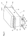
- the laminated stator core 26 is segmented and made of a plurality of identical, T-shaped stator segments 28 (FIG. Fig. 2 ), which are received by the stator 24 and held together.
- Each of the stator segments 28 has a yoke region 30 and a tooth 32 directed radially inward on the stator 16, which tooth is equipped with a single coil 36 to form the winding 34.
- the coil ends of the individual coils 36 are, as will be explained in more detail in the further course of the description, by means of a in Fig. 1 only schematically illustrated interconnecting device 38 connected and connected to a power electronics not shown in the drawing, soft to operate the electric machine 10, the winding 34 can act on a variable-phase current and amplitude.
- the individual coils 36 are wound before the assembly of the stator 16 by means of two, consisting of a heat-resistant plastic insulating or bobbins 40, 42 of a copper wire around the teeth 32 and there are formed by a radially inward into the FIGS. 1 . 2 Concealed tooth head secured against slipping.
- the bobbins 40, 42 each include a front side on the laminated core 26 adjacent base portion 44 ( Fig. 1 ) and two of them approximately at right angles protruding legs 40a, b; 42a, b which limit the winding area in the radial direction.
- the insulating body 40, 42 may also simultaneously cover the longitudinal sides of the teeth 32 and also in one piece, ie be performed together, wherein at least one parting line is provided for mounting them on the teeth 32. To compensate for tolerances, a mutual overlap of the subregions is advantageous in the region of the parting line.
- the teeth 32 can be encapsulated to form the insulating body on the longitudinal and end sides with a plastic, so that the entire, the winding area delimiting peripheral surface of a tooth 32 is isolated.
- each of the insulating body 40 with respect to the stator 16 axially exiting contact elements 50 has a U-shaped bent contact portion 50a and a strip-shaped contact portion 50b in the form of a pin.
- a winding end 36a, b coming from the angular range and guided within the limb 46a in each case is inserted, where it is preferably firmly bonded, eg, by soldering or welding, and thus set relieved of strain.
- connection conductors 52a-c are designed as band conductors made of copper and bent into a preferably open ring.
- a band-shaped connecting conductor 53a-c is connected, the free end of which has an eyelet into which a contact pin 54a-c is soldered or welded in order to connect a power cable.
- the connection conductors 52a-c have over-connection areas 52, which have been formed by a forming process in the present example, with respect to their base bodies.
- the coils 36 are connected according to a delta connection.
- the particular type of wiring is irrelevant to the following explanations, i.
- a star connection or still another connection could also be realized by using a further, fourth connection conductor.
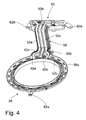
- connection conductors 52a-c are accommodated by an annular carrier element 56 formed as a plastic, as in FIG Fig. 4 shown.
- the support member 56 is supported in Fig. 1 axially on the insulators 40 of the coils 36 and is also centered radially by the defined by these inner peripheral surface.
- On the support member 56 also a directed radially outward insertion portion 58 is formed or arranged for mutually insulated receiving the three terminal conductors 53a-c, which at the free end of a terminal housing 60 for receiving and connecting the contact pin 54a-c is formed.
- the assembly formed from the elements 56, 58, 60 and preferably produced as injection-molded parts comprises a plurality of fastening sections 62 ae, which are screwed to the stator carrier 24 by means of bolts.
- fastening sections 62 ae which are screwed to the stator carrier 24 by means of bolts.
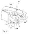
- Fig. 5 shows a detail of a perspective sectional view of the support structure 56, which is designed as a unilaterally open profile with a stepped bottom 56a, b and perpendicularly projecting side walls 56c, d, e and by dividers 56f, g for the isolated arrangement of the connecting conductors 52a-c in a plurality of annular chambers 56h-k is divided. It can be seen that the side walls 56c, d overhang the separating webs 56f, g and the wall region 56e, thereby forming an open annular space adjacent to the annular chambers 56h-k as a connecting region 56o, in which the connecting conductors 52a-c with the coil terminals 50b are electrically connected.
- the dividing webs 56f, g at the exit positions of the coil terminals 50b for avoiding short circuits with respect to the connecting conductors 52a-c are provided with elevations 56I which, as in FIG Fig. 6 can be used as a support of the coil terminals 50b.
- a number of windows 56m corresponding to the coil terminals 50b are formed, through which the coil terminals 50b, which are initially oriented axially on the stator 16, are passed.
- the in Fig. 4 illustrated unit as in Fig.1 schematically shown on the stator 16 and fixed there by means of the mounting portions 62 ae. It is based on the perspective Statorausiteses the Fig. 6 It can be seen that the carrier element 56 with the connecting conductors 52a, b, c is thus located directly axially adjacent to the exit regions of the coil terminals 50b from the coils 36 and covers them radially.
- the coil terminals or pins 50b are already passed through the formed in the support member 56 window 56m and bent within the annular space or Verschaltungs Schemees 56o by 90 ° radially inward so that they are initially spaced from the connecting conductors 52a-c and only with their raised connection areas 52e come into contact.
- the pins are 50b at the same time at the elevations 56I formed there of the dividing webs 56f, g and are supported there. It can be seen that in each case two coil terminals 50b of in each case two directly adjacent coils 36 are electrically connected to one of the connecting conductors 52a-c.
- the contacting is preferably cohesively, for example by soldering or welding.
- connection areas 52e are made longer in the circumferential direction of a connection conductor 52a-c than the coil terminals 50b extend in this direction, so that tolerance-related positioning deviations of the contact points occurring in the parts production and / or assembly pose no problems. It will also be seen that also the U-shaped terminal portions 50a with the winding ends 36a, b connected therein are passed through the windows 56m and are thus also in the interconnecting area 56o.
- connection conductors 52a-c To protect the connecting conductors 52a-c, the coil terminals 50b and the contact areas of the winding end 36a, b, and the connecting conductor 53a-c against corrosion and also to increase the stability of the interconnection device of the connection area 56o of the support member 56 is complete after connection with a sealant , For example, with a resin or silicone potted, wherein the windows 56m and projecting beyond the coils contact elements 50, including the contact portions 50b are completely sealed from the environment.
- a sealant For example, with a resin or silicone potted, wherein the windows 56m and projecting beyond the coils contact elements 50, including the contact portions 50b are completely sealed from the environment.
- the pins 50b may also be designed with slots, these each take a bent by a connecting conductor 52a-c connection area and there by soldering, welding o.ä. can be connected.
- the connecting regions of the connecting conductors 52a-c can also be crimped in a manner already known with the coil terminals.
- the coil wire or a contact pin can preferably be inserted into a region formed from the base region and a connecting region projecting therefrom, and then the protruding connecting region can be bent over, wherein a coil connection is fixed to the connecting conductor.
- the coil terminals can also be formed directly by the coil end of the coils.
- these can also be arranged axially staggered relative to the stator and the other elements can be adapted accordingly if necessary.
- the special design of the electrical machine with respect to the basic design of the stator interconnection device is irrelevant; For example, it may also be an external-type electric machine.
Landscapes
- Engineering & Computer Science (AREA)
- Power Engineering (AREA)
- Insulation, Fastening Of Motor, Generator Windings (AREA)
- Windings For Motors And Generators (AREA)
Abstract
Description
Die Erfindung betrifft einen Stator für eine elektrische Maschine gemäß dem Oberbegriff des Patentanspruchs 1.The invention relates to a stator for an electric machine according to the preamble of patent claim 1.
Ein gattungsgemäßer Stator wird beispielsweise in der
Die erläuterte Verschaltungseinrichtung ist bei einem Außenläufermotor vorteilhaft, jedoch bei einem Innenläufer nur bedingt anwendbar. Unabhängig von der Verschaltungsvariante ist die Handhabung der Spulenenden und insbesondere Biegestellen kritisch, weil an diesen die empfindliche Lackschicht aufreißen und Feuchtigkeit angreifen kann, welche in Folge zu Korrosionserscheinungen und zum Ausfall von Wicklungskomponenten führen kann.The described interconnection device is advantageous in an external rotor motor, but only partially applicable to an internal rotor. Regardless of the Verschaltungsvariante the handling of the coil ends and in particular bending points is critical, because at these the sensitive lacquer layer can rupture and attack moisture, which can lead to corrosion and failure of winding components in a row.
Es ist die Aufgabe der vorliegenden Erfindung, einen Stator der vorgenannten Art so zu verbessern, dass insbesondere dessen Verschaltungseinrichtung prozesssicherer gestaltet, gegenüber Fertigungs- und Montagetoleranzen unempfindlich und gleichermaßen für einen Innen- oder Außenläufermotor geeignet ist.It is the object of the present invention to improve a stator of the aforementioned type so that in particular its interconnection device designed more reliable, insensitive to manufacturing and assembly tolerances and equally suitable for an internal or external rotor motor.
Die Erfindung löst diese Aufgabe bei einem Stator der eingangs genannten Art durch die im Kennzeichen des Patentanspruchs 1 aufgeführten Merkmale. Vorteilhafte Ausgestaltungen der Erfindungen sind in den Unteransprüchen wiedergegeben.The invention solves this problem in a stator of the type mentioned by the features listed in the characterizing part of patent claim 1. Advantageous embodiments of the invention are given in the subclaims.
Gemäß der Erfindung wird ein Stator für eine elektrische Maschine mit einem ringförmigen Statorjoch vorgeschlagen, an dem in Umfangsrichtung eine Mehrzahl radial abragender Statorzähne angeordnet ist, an denen Spulen mit Spulenanschlüssen angeordnet sind. Zur Verschaltung mit den Spulenanschlüssen sind an dem Stator ringförmige Verbindungsleiter vorgesehen, die konzentrisch zueinander und elektrisch gegeneinander isoliert in einem zu den Spulen benachbarten Verschaltungsbereich eines Trägerelementes angeordnet und dort in einer vorbestimmten Weise mit den Spulenanschlüssen verbunden sind.According to the invention, a stator for an electric machine with an annular stator yoke is proposed, on which in the circumferential direction a plurality of radially projecting stator teeth is arranged, arranged on which coils with coil terminals are. For connection to the coil terminals ring-shaped connecting conductors are provided on the stator, which are arranged concentrically to each other and electrically insulated from each other in an adjacent to the coils interconnection region of a support member and connected there in a predetermined manner with the coil terminals.
Der Stator zeichnet sich insbesondere dadurch aus, dass die Spulenanschlüsse bezüglich des Stators axial aus den Spulen austreten und dass in einem Wandungsbereich des Trägerelementes zu den Spulenanschlüssen korrespondierende Ausnehmungen ausgebildet sind, durch welche die Spulenanschlüsse in den Verschaltungsbereich des Trägerelements axial eingeführt sind, wobei der Wandungsbereich des Trägerelements den Austrittsbereich der Spulenanschlüsse aus den Spulen radial überdeckt.The stator is characterized in particular in that the coil terminals axially emerge from the coils with respect to the stator and that recesses are formed in a wall region of the carrier element to the coil terminals, through which the coil terminals are inserted axially into the interconnection region of the carrier element, wherein the wall region the support member radially covers the exit region of the coil terminals from the coils.
Beim Bewickeln der Spulen wird durch den gewundenen Wickelleiter, z.B. einem Wickeldraht, eine Windungsebene definiert. Die vorgeschlagene Lösung bietet den Vorteil, dass die nach dem Bewickeln in einer Windungsebene liegenden Spulenanschlüsse axial ausgerichtet innerhalb dieser Windungsebene verbleiben können und für die Verschaltung mit den Verbindungsleitern zur Verfügung stehen. Dazu wird das die Verbindungsleiter beherbergende Tragelement an die Verschaltungsseite des Stators axial herangeführt, wobei die Spulenanschlüsse durch im Wandungsbereich vorgesehene Ausnehmungen in den Verschaltungsbereich eingeführt werden können. Bei erfolgter Anlage überdeckt der Wandungsbereich des Trägerelementes den Austrittsbereich der Spulenanschlüsse aus den Spulen. Somit ist der Übergang der Spulenanschlüsse in den Verschaltungsbereich möglich, ohne dass diese dazu aus deren Windungsebene abgebogen werden müssen.When winding the coils, a winding plane is defined by the wound winding conductor, eg a winding wire. The proposed solution has the advantage that the coil terminals located after winding in a winding plane can remain axially aligned within this winding plane and are available for the connection to the connecting conductors. For this purpose, the support element accommodating the connection conductor is brought axially to the connection side of the stator, wherein the coil connections can be introduced into the connection region by recesses provided in the wall region. When the system has been completed, the wall region of the carrier element covers the exit region of the coil connections from the coils. Thus, the transition of the coil terminals into the interconnection area possible, without that they have to be bent from the winding level.
Vorteilhafte Weiterbildungen und Ausgestaltungen der Erfindungen sind in den Unteransprüchen angegeben.Advantageous developments and refinements of the inventions are specified in the subclaims.
Mit Vorteil sind die Spulen mit zumindest einem Isolierkörper an den Zähnen angeordnet, wobei die Spulenanschlüsse in dem Isolierkörper verlegt sind. Ein solcher Isolier- bzw. Wickelkörper isoliert den Spulenleiter gegenüber dem Statorjoch und begrenzt gleichzeitig einen Wickelbereich, so dass die Spule kompakt und dauerhaft formstabil ausgebildet werden kann.Advantageously, the coils are arranged with at least one insulating body on the teeth, wherein the coil terminals are laid in the insulating body. Such insulating or winding body isolates the coil conductor relative to the stator yoke and at the same time limits a winding region, so that the coil can be made compact and permanently dimensionally stable.
Mit besonderem Vorteil kann sich das Trägerelement an mehreren Isolierkörpern am Stator abstützen, wobei diese zumindest eine gemeinsame axiale und/oder radiale Anlagefläche ausbilden.With particular advantage, the support element can be supported on a plurality of insulating bodies on the stator, wherein these form at least one common axial and / or radial contact surface.
Die zur Verschaltung mit den Verbindungsleitern vorgesehenen Spulenanschlüsse können direkt durch die Wicklungsende der Spulen gebildet werden. Alternativ können die Wicklungsenden auch an den Isolier- bzw. Wickelkörpern zugentlastet festgelegt sein und dort mit Kontaktabschnitten von Kontaktelementen verbunden sein, welche ebenfalls an den Wickelkörper fixiert sind und in diesem Fall die Spulenanschlüsse ausbilden. Auch hierbei verbleiben die Wicklungsende axial ausgerichtet in der Windungsebene und bei der Montage der Spulen und der Verschaltungseinrichtung am Stator kräftefrei.The coil terminals provided for connection to the connecting conductors can be formed directly by the coil end of the coils. Alternatively, the winding ends can also be fixed to the insulating or winding bodies with strain relief and connected there to contact sections of contact elements which are likewise fixed to the winding body and in this case form the coil terminals. Here, too, the winding end remain axially aligned in the winding plane and during assembly of the coils and the interconnecting device on the stator force-free.
Gemäß einer bevorzugten Ausführungsform sind die Kontaktabschnitte mit den dort verbundenen Wicklungsende ebenfalls durch die Fenster bzw. Ausnehmungen des Trägerelementes in den Verschaltungsbereich des Trägerelementes axial eingeführt.According to a preferred embodiment, the contact portions with the winding end connected there are also inserted axially through the windows or recesses of the carrier element in the Verschaltungsbereich of the support element.
Es ist gemäß einer weiteren Ausgestaltung der Erfindung fertigungstechnisch äußerst zweckmäßig, das Trägerelement als einseitig offenes Kunststoff-Profil mit einem Boden und mit daran anschließenden Seitenwandungen auszuführen, die den Verschaltungsbereich nach außen begrenzen. Zur gegenseitig isolierten Anordnung der Verbindungsleiter sind innerhalb des Trägerelementes mehrere Trennstege vorgesehen, die vorzugsweise integral mit dem Grundkörper des Trägerelementes eingebracht werden. Für die weitere Verschaltung ist es sinnvoll, wenn die Trennstege die Verbindungsleiter überragen, so dass ein elektrischer Kontakt zwischen einem Spulenanschluss nur an den dafür vorgesehenen Stellen erfolgt und ansonsten zwischen den potentialführenden Leitern Isolationszwischenräume erzeugt werden. Die Seitenwandungen sind so geformt, dass diese die Trennstege überragen. Damit wird als Verschaltungsbereich ein wannenförmiger Aufnahmeraum geschaffen, welcher mit einem Dichtmittel, z.B. mit einem Deckelement oder mit einem Harz, Silikon oder einem anderen Füllstoff dichtend verschlossen bzw. vergossen werden kann, wobei die Verbindungsleiter, die Wicklungsende, die Spulenanschlüsse und deren gegenseitige Kontaktbereiche sowie die Fenster des Trägerelementes dichtend verschlossen sind.It is according to a further embodiment of the invention manufacturing technology extremely expedient to perform the support element as a one-sided open plastic profile with a bottom and adjoining side walls that limit the wiring area to the outside. For mutually insulated arrangement of the connecting conductors, a plurality of separating webs are provided within the carrier element, which are preferably incorporated integrally with the base body of the carrier element. For the further interconnection, it is useful if the dividers project beyond the connecting conductors, so that an electrical contact between a coil connection takes place only at the designated locations and otherwise between the potential-carrying conductors insulation gaps are generated. The side walls are shaped so that they project beyond the dividers. Thus, a trough-shaped receiving space is created as an interconnecting area, which is provided with a sealing means, e.g. can be sealed or potted with a cover element or with a resin, silicone or other filler, wherein the connecting conductor, the coil end, the coil terminals and their mutual contact areas and the window of the support element are sealed.
Zur Überbrückung der Isolationszwischenräume und der Erzeugung eines Kontaktbereiches zwischen den Spulenanschlüssen und den Verbindungsleitern weisen die Verbindungsleiter an vorbestimmten Positionen von diesen zur offenen Seite des Verschaltungsbereiches abstehende Anschlussbereiche auf. Diese Anschlussbereiche können auf einfache Art und Weise als Präge- oder Stanzelemente an den Verbindungsleitern ausgebildet werden. Als Verbindungsleiter eignet sich besonders ein band- oder drahtförmiges Material mit einem geringen elektrischen Widerstand, bevorzugt Kupfer, welches zur Anordnung in dem Verschaltungsbereich in eine Ringform gebogen ist. Die ringförmigen Verbindungsleiter können in Umfangsrichtung geschlossen oder bevorzugt offen sein, um bei thermisch induzierten Längenänderungen einen Bewegungsspielraum zu haben.For bridging the insulation gaps and the generation of a contact region between the coil terminals and the connecting conductors, the connecting conductors at predetermined positions of these to the open side of the Verschaltungsbereiches projecting connection areas. These connection areas can be formed in a simple manner as embossing or stamping elements on the connecting conductors. As a connecting conductor is particularly suitable a band or wire-shaped material with a low electrical resistance, preferably copper, which is bent to be arranged in the Verschaltungsbereich in a ring shape. The annular connecting conductors can be closed in the circumferential direction or preferably open to have a movement latitude in thermally induced changes in length.
Die Verbindungsleiter können axial gestaffelt am Stator angeordnet sein. In diesem Fall kann das Trägerelement mit einer Seitenwandung am Stator anliegen und sich dort abstützen, wobei die durch die Ausnehmungen in den Verschaltungsbereich ragenden Spulenanschlüsse unmittelbar verschaltet werden können.The connecting conductors can be arranged axially staggered on the stator. In this case, the carrier element can rest against the stator with a side wall and be supported there, wherein the coil connections projecting through the recesses into the connection region can be connected directly.
Gemäß einer dazu alternativen Variante können die Verbindungsleiter auch radial gestaffelt am Stator angeordnet werden, wobei das Trägerelement mit einem der offenen Seite gegenüberliegenden Bodenbereich am Stator anliegen kann und sich dort abstützen kann. Die durch die Ausnehmungen axial in den Verschaltungsbereich ragenden Spulenanschlüsse werden innerhalb des Verschaltungsbereiches um 90° radial abgebogen, so dass diese die Verbindungsleiter kreuzen und mittels der von diesen abstehenden Anschlussbereiche verschaltet werden können.According to an alternative variant, the connecting conductors can also be arranged radially staggered on the stator, wherein the carrier element can abut against the stator with a bottom area lying opposite the open side and can be supported there. The coil terminals projecting axially through the recesses into the interconnection area are bent radially by 90 ° within the interconnection area so that they intersect the connection conductors and can be interconnected by means of the connection areas projecting from them.
Zum Anschluss des Stators an eine Stromversorgungseinrichtung sind die Verbindungsleiter mit Anschlussleitern verbunden, welche gleichfalls in einen am Trägerelement ausgebildeten Einlegeabschnitt angeordnet sind und dort ebenfalls mit einem Dichtmittel vergossen werden können.For connecting the stator to a power supply device, the connecting conductors are connected to connecting conductors, which are likewise arranged in an insertion section formed on the carrier element and can likewise be cast there with a sealing agent.
Die Erfindung wird im Folgenden mittels der beigefügten Figuren beispielhaft erläutert. Es zeigen:
- Fig. 1
- eine schematische Darstellung einer elektrischen Maschine in Innenläuferbauart;
- Fig.2
- ein mit einer Einzelspule bestücktes T-förmiges Statorsegment der in
Fig. 1 gezeigten elektrischen Maschine; - Fig. 3
- einen ringförmigen Verbindungsleiter mit einem daran angeordneten Anschlussleiter;
- Fig. 4
- eine vormontierte Baueinheit aus einem Trägerelement, einem Einlegeabschnitt und einem Anschlussgehäuseteil mit darin angeordneten Stromleitern;
- Fig. 5
- ein Ausschnitt des Trägerelementes in einer perspektivischen Schnittdarstellung;
- Fig. 6
- ein Ausschnitt eines mit Einzelspulen bestückten Stators mit einer Verschaltungseinrichtung in einer perspektivischen Darstellung.
- Fig. 1
- a schematic representation of an electric machine in Innenläuferbauart;
- Fig.2
- a fitted with a single coil T-shaped stator segment of in
Fig. 1 shown electric machine; - Fig. 3
- an annular connecting conductor having a terminal conductor disposed thereon;
- Fig. 4
- a preassembled unit consisting of a carrier element, an insert section and a connection housing part with conductors arranged therein;
- Fig. 5
- a detail of the carrier element in a perspective sectional view;
- Fig. 6
- a section of a stator equipped with individual coils with an interconnection device in a perspective view.
Der Stator 16 umfasst einen metallischen, beispielsweise aus einem Aluminium- oder einem Stahlwerkstoff hergestellten ringförmigen Statorträger 24, in dessen Ausnehmung ein ebenfalls aus Blechlamellen gebildetes kreisringförmiges Statorblechpaket 26 angeordnet ist. Der Statorträger 24 kann damit ein Außen- oder ein Zwischengehäuse der elektrischen Maschine 10 darstellen. Das Statorblechpaket 26 ist hierbei segmentiert ausgeführt und aus einer Mehrzahl von identischen, T-förmigen Statorsegmenten 28 (
Jedes der Statorsegmente 28 weist einen Jochbereich 30 und einen am Stator 16 nach radial innen gerichteten Zahn 32 auf, welcher zur Bildung der Wicklung 34 mit einer Einzelspule 36 bestückt ist. Die Spulenenden der Einzelspulen 36 sind, wie dieses im weiteren Verlauf der Beschreibung noch ausführlicher erläutert wird, mittels einer in
Die Einzelspulen 36 werden vor der Montage des Stators 16 mit Hilfe von jeweils zwei, aus einem wärmebeständigen Kunststoff bestehenden Isolier- bzw. Wickelkörpern 40, 42 aus einem Kupferdraht um die Zähne 32 gewickelt und sind dort durch einen radial innen ausgebildeten, in den
Alternativ zu vorgefertigten Isolierkörpern 40, 42 können die Zähne 32 zur Bildung der Isolierkörper auch an den Längs- und Stirnseiten mit einem Kunststoff umspritzt werden, so dass die gesamte, den Wickelbereich begrenzende Umfangsfläche eines Zahns 32 isoliert ist.As an alternative to prefabricated insulating
An einer Stirnseite des Stators 16 sind an den radial inneren Schenkeln 40a der Isolierkörper 40 jeweils zwei Kontaktelemente 50 festgelegt, die dort eingesteckt oder beim Spritzgießen der Isolierkörper 40 als Einlegeteil teilweise umspritzt werden, wobei jedes der vom Isolierkörper 40 bezüglich des Stators 16 axial austretenden Kontaktelemente 50 einen U-förmig gebogenen Kontaktabschnitt 50a und einen streifenförmigen Kontaktabschnitt 50b in Form eines Pins aufweist. In den U-förmigen Kontaktabschnitt 50a wird jeweils ein vom Winkelbereich kommendes und innerhalb des Schenkels 46a in einer Nut geführtes Wicklungsende 36a, b eingelegt und dort vorzugsweise stoffschlüssig z.B. durch Verlöten oder Verschweißen verbunden und damit zugentlastet festgelegt. In
Die Spulen 36 sind elektrisch einzelnen Strängen zugeordnet und werden, wie weiter unten noch ausgeführt, mittels der Verschaltungseinrichtung 38 über gemeinsame Verbindungsleiter 52a-c, von denen in
Im erläuterten Ausführungsbeispiel sind die Spulen 36 nach einer Dreieckschaltung verschaltet. Jedoch ist die jeweilige Verschaltungsart für die nachfolgenden Erläuterungen unerheblich, d.h. alternativ könnte auch unter Verwendung eines weiteren, vierten Verbindungsleiters eine Sternschaltung oder eine noch andere Verschaltung verwirklicht werden.In the illustrated embodiment, the
Zur Anordnung der Verbindungsleiter 52a-c am Stator 16 sind diese von einem als Kunststoff ausgebildeten ringförmigen Trägerelement 56 aufgenommen, wie in
Zur Verschaltung der Spulenanschlüsse 50b wird die in
In
Zum Schutz der Verbindungsleiter 52a-c, der Spulenanschlüsse 50b und der Kontaktbereiche der Wicklungsende 36a, b, sowie der Anschlussleiter 53a-c vor Korrosionserscheinungen und gleichfalls zur Erhöhung der Stabilität der Verschaltungseinrichtung wird der Verschaltungsbereich 56o des Trägerelementes 56 nach erfolgter Verschaltung komplett mit einem Dichtmittel, beispielsweise mit einem Harz oder Silikon vergossen, wobei auch die Fenster 56m und die an den Spulen herausstehenden Kontaktelemente 50, also auch der Kontaktabschnitte 50b vollständig gegenüber der Umgebung abgedichtet werden.To protect the connecting
In einer zeichnerisch nicht dargestellten Abwandlung der erläuterten Verschaltungseinrichtung können die Pins 50b auch mit Schlitzen ausgeführt sein, wobei diese jeweils einen von einem Verbindungsleiter 52a-c abgebogenen Anschlussbereich aufnehmen und dort durch Verlöten, Verschweißen o.ä. verbunden werden können.In a graphically not shown modification of the described interconnection device, the
Die Anschlussbereiche der Verbindungsleiter 52a-c können auch in bereits bekannter Weise mit den Spulenanschlüssen eine Crimpverbindung eingehen. Dazu kann bevorzugt der Spulendraht oder ein Kontaktpin in einen aus dem Basisbereich und einem davon abstehenden Anschlussbereich gebildeten Bereich eingelegt und dann der abstehende Anschlussbereich umgebogen werden, wobei ein Spulenanschluss an dem Verbindungsleiter fixiert wird.The connecting regions of the connecting
Alternativ zu dem erläuterten Ausführungsbeispiel können die Spulenanschlüsse auch unmittelbar durch die Wicklungsende der Spulen gebildet werden.Alternatively to the illustrated embodiment, the coil terminals can also be formed directly by the coil end of the coils.
Anstelle der dargestellten radialen Staffelung der Verbindungsleiter können diese auch axial gestaffelt zum Stator angeordnet und die weiteren Elemente sofern erforderlich entsprechend angepasst werden.Instead of the illustrated radial staggering of the connecting conductors, these can also be arranged axially staggered relative to the stator and the other elements can be adapted accordingly if necessary.
Auch ist die spezielle Bauart der elektrischen Maschine hinsichtlich der prinzipiellen Ausführung der Stator-Verschaltungseinrichtung unerheblich; es kann sich also beispielsweise auch um eine elektrische Maschine in Außenläuferbauart handeln.Also, the special design of the electrical machine with respect to the basic design of the stator interconnection device is irrelevant; For example, it may also be an external-type electric machine.
Claims (18)
dass die Spulenanschlüsse (50b) bezüglich des Stators (16) axial aus den Spulen (36) austreten und dass in einem Wandungsbereich (56b) des Trägerelementes (56) zu den Spulenanschlüssen (50b) korrespondierende Ausnehmungen (56m) ausgebildet sind, durch welche die Spulenanschlüsse (50b) in den Verschaltungsbereich (56o) des Trägerelementes (56) axial eingeführt sind, wobei der Wandungsbereich (56b) des Trägerelementes (56) einen Austrittsbereich der Spulenanschlüsse (50b) aus den Spulen (36) radial überdeckt.Stator (16) for an electrical machine (10) comprising
in that the coil terminals (50b) emerge axially from the coils (36) with respect to the stator (16) and that recesses (56m) which correspond to the coil terminals (50b) are formed in a wall region (56b) of the carrier element (56) Coil terminals (50b) are axially inserted into the interconnection area (56o) of the carrier element (56), wherein the wall area (56b) of the carrier element (56) radially covers an exit area of the coil terminals (50b) from the coils (36).
dadurch gekennzeichnet,
dass eine Spule (36) mit zumindest einem Isolierkörper (40) an einem Zahn (32) angeordnet ist, wobei die Spulenanschlüsse (50b) an dem Isolierkörper (40) festgelegt sind.Stator according to claim 1,
characterized,
in that a coil (36) with at least one insulating body (40) is arranged on a tooth (32), wherein the coil terminals (50b) are fixed to the insulating body (40).
dadurch gekennzeichnet,
dass sich das Trägerelement (56) an mehreren Isolierkörpern (40) am Stator (16) abstützt.Stator according to claim 1 or 2,
characterized,
in that the carrier element (56) is supported on a plurality of insulating bodies (40) on the stator (16).
dadurch gekennzeichnet,
dass die Spulenanschlüsse unmittelbar durch Wicklungsende (36a, b) der Spulen (36) gebildet werden.Stator according to one of claims 1-3,
characterized,
in that the coil terminals are formed directly by winding ends (36a, b) of the coils (36).
dadurch gekennzeichnet,
dass die Spulenanschlüsse (50b) durch Kontaktelemente (50) gebildet werden, die an den Isolierkörpern (40) festgelegt und mit den Spulenenden (36a, b) verbunden sind.Stator according to one of claims 1-3,
characterized,
in that the coil terminals (50b) are formed by contact elements (50) fixed to the insulating bodies (40) and connected to the coil ends (36a, b).
dadurch gekennzeichnet,
dass die Kontaktelemente (50) Kontaktabschnitte (50a) zur Verbindung mit den Wicklungsende (36a,b) aufweisen.Stator according to claim 5,
characterized,
in that the contact elements (50) have contact sections (50a) for connection to the winding end (36a, b).
dadurch gekennzeichnet,
dass die Kontaktabschnitte (50a) mit den Wicklungsende (36a, b) durch die Ausnehmungen (56m) in den Verschaltungsbereich (56o) des Trägerelementes (56) eingeführt sind.Stator according to one of claims 1-6,
characterized,
in that the contact sections (50a) with the winding end (36a, b) are inserted through the recesses (56m) into the connection region (56o) of the carrier element (56).
dadurch gekennzeichnet,
dass das Trägerelement (56) als einseitig offenes Profil mit einem Boden (56a, b) und mit daran anschließenden Seitenwandungen (56c-e) ausgeführt ist, welche den Verschaltungsbereich (56o) begrenzen.Stator according to one of claims 1-7,
characterized,
in that the carrier element (56) is designed as a one-sided open profile with a bottom (56a, b) and with adjoining side walls (56c-e) which delimit the connection region (56o).
dadurch gekennzeichnet,
dass das Trägerelement (56) Trennstege (56f, g) zur gegenseitig isolierten Anordnung der Verbindungsleiter (52a-c) aufweist.Stator according to one of claims 1-8,
characterized,
in that the carrier element (56) has separating webs (56f, g) for the mutually insulated arrangement of the connecting conductors (52a-c).
dadurch gekennzeichnet,
dass die Trennstege (56f, g) die Verbindungsleiter (52a-c) zumindest abschnittweise überragen.Stator according to claim 9,
characterized,
that the separating webs (56f, g) at least in sections, the connecting conductors (52a-c) overtop.
dadurch gekennzeichnet,
dass die Seitenwandungen (56c, d) die Trennstege (56f, g) überragen.Stator according to claim 9 or 10,
characterized,
in that the side walls (56c, d) project beyond the partitions (56f, g).
dadurch gekennzeichnet,
dass die Verbindungsleiter (52a-c) von diesen abstehende Anschlussbereiche (52e) zur Verbindung mit den Spulenanschlüssen (50b) aufweisen.Stator according to one of claims 1-11,
characterized,
in that the connecting conductors (52a-c) have connecting regions (52e) protruding from them for connection to the coil terminals (50b).
dadurch gekennzeichnet,
dass die Anschlussbereiche (52e) als Präge- oder Stanzelemente an den Verbindungsleitern (52a-c) ausgebildet sind.Stator according to claim 12,
characterized,
that the terminal portions (52e) are formed as stamping or punching elements at the connecting conductors (52a-c).
dadurch gekennzeichnet,
dass die Verbindungsleiter (52a-c) axial gestaffelt am Stator (16) angeordnet sind.Stator according to one of claims 1-13,
characterized,
in that the connecting conductors (52a-c) are arranged axially staggered on the stator (16).
dadurch gekennzeichnet,
dass die Verbindungsleiter (52a-c) radial gestaffelt am Stator (16) angeordnet und die Spulenanschlüsse (50b) innerhalb des Trägerelementes (56) abgewickelt sind.Stator according to one of claims 1-13,
characterized,
in that the connecting conductors (52a-c) are arranged radially staggered on the stator (16) and the coil terminals (50b) are unwound within the carrier element (56) are.
dadurch gekennzeichnet,
dass der Verschaltungsbereich (56o) des Trägerelements (56) mit einem Dichtmittel verschlossen oder vergossen ist.Stator according to one of claims 1-15,
characterized,
is that the Verschaltungsbereich (56o) of the carrier element (56) closed with a sealant or encapsulated.
dadurch gekennzeichnet,
dass die Verbindungsleiter (52a-c) zum Anschluss des Stators (16) an eine Stromversorgungseinrichtung mit Anschlussleitern (53a-c) verbunden sind.Stator according to one of claims 1-16,
characterized,
in that the connection conductors (52a-c) for connection of the stator (16) to a power supply device are connected to connection conductors (53a-c).
dadurch gekennzeichnet,
dass die Anschlussleiter (53a-c) in einen am Trägerelement (56) ausgebildeten oder mit diesem verbundenen Einlegeabschnitt (58) angeordnet sind.Stator according to claim 17,
characterized,
arranged that the connecting conductors (53a-c) formed into a on the carrier element (56) or connected thereto loading section (58).
Priority Applications (3)
| Application Number | Priority Date | Filing Date | Title |
|---|---|---|---|
| EP08159055.6A EP2139094B1 (en) | 2008-06-26 | 2008-06-26 | Stator and connecting arrangement of an electric machine |
| US12/491,405 US8183728B2 (en) | 2008-06-26 | 2009-06-25 | Stator for an electric machine |
| CN200910146282.5A CN101615818B (en) | 2008-06-26 | 2009-06-26 | Stator for electric machine |
Applications Claiming Priority (1)
| Application Number | Priority Date | Filing Date | Title |
|---|---|---|---|
| EP08159055.6A EP2139094B1 (en) | 2008-06-26 | 2008-06-26 | Stator and connecting arrangement of an electric machine |
Publications (2)
| Publication Number | Publication Date |
|---|---|
| EP2139094A1 true EP2139094A1 (en) | 2009-12-30 |
| EP2139094B1 EP2139094B1 (en) | 2018-10-17 |
Family
ID=40110957
Family Applications (1)
| Application Number | Title | Priority Date | Filing Date |
|---|---|---|---|
| EP08159055.6A Active EP2139094B1 (en) | 2008-06-26 | 2008-06-26 | Stator and connecting arrangement of an electric machine |
Country Status (3)
| Country | Link |
|---|---|
| US (1) | US8183728B2 (en) |
| EP (1) | EP2139094B1 (en) |
| CN (1) | CN101615818B (en) |
Cited By (13)
| Publication number | Priority date | Publication date | Assignee | Title |
|---|---|---|---|---|
| FR2963174A1 (en) * | 2010-07-22 | 2012-01-27 | Ssd Parvex Sas | Stator for electric motor, has annular body comprising teeth distributed regularly on interior surface and coils placed around each tooth, where thickness of each of coils is less than specific value of thickness of tooth |
| DE102011077294A1 (en) | 2011-06-09 | 2012-12-13 | Zf Friedrichshafen Ag | Electric machine with a power connection unit |
| DE102012008651A1 (en) * | 2012-05-03 | 2013-11-07 | Sew-Eurodrive Gmbh & Co Kg | Electric motor and method for manufacturing an electric motor |
| DE202014003844U1 (en) | 2014-03-20 | 2014-06-11 | Wieland-Werke Ag | Interconnection arrangement and stator with a wiring arrangement |
| DE102012223371A1 (en) * | 2012-12-17 | 2014-06-18 | Zf Friedrichshafen Ag | Stator for an electric machine |
| DE102013214386A1 (en) | 2013-07-23 | 2015-01-29 | Zf Friedrichshafen Ag | Electric machine |
| WO2015082220A3 (en) * | 2013-12-03 | 2015-09-11 | Pierburg Gmbh | Stator for an electronically commutated direct current motor |
| DE102014211923A1 (en) | 2014-06-23 | 2015-12-24 | Zf Friedrichshafen Ag | Electric machine with a stator wiring arrangement |
| WO2016041704A1 (en) * | 2014-09-18 | 2016-03-24 | Zf Friedrichshafen Ag | Stator for an electrical machine having a connecting apparatus |
| WO2016119971A1 (en) * | 2015-01-26 | 2016-08-04 | Zf Friedrichshafen Ag | Stator for an electric machine having an encapsulated connecting apparatus |
| WO2016180588A1 (en) * | 2015-05-13 | 2016-11-17 | Zf Friedrichshafen Ag | Stator for an electrical machine having an encapsulated interconnection device, and electrical machine having such a stator |
| DE102016208150A1 (en) * | 2016-05-12 | 2017-11-16 | Zf Friedrichshafen Ag | Stator of an electrical machine with a connection device for stator coils and electrical machine with such a stator |
| DE102022110460A1 (en) | 2022-04-29 | 2023-11-02 | Voith Patent Gmbh | Interconnection module |
Families Citing this family (28)
| Publication number | Priority date | Publication date | Assignee | Title |
|---|---|---|---|---|
| DE102009036128A1 (en) * | 2009-08-05 | 2011-02-10 | Brose Fahrzeugteile Gmbh & Co. Kg, Hallstadt | Electrical component of a motor vehicle |
| DE102010033699B4 (en) * | 2010-07-30 | 2020-10-29 | Stöber Antriebstechnik GmbH & Co. KG | Switching head for electric motors and a method for connecting a switching head to the connecting strands of an electric motor winding |
| JP5263368B2 (en) * | 2011-03-08 | 2013-08-14 | 株式会社豊田自動織機 | Electric compressor and assembling method of electric compressor |
| EP2562915B1 (en) * | 2011-08-24 | 2015-05-20 | Sumitomo Wiring Systems, Ltd. | Central power supply member and method of assembling it |
| EP2571145B1 (en) * | 2011-09-13 | 2017-08-02 | General Electric Technology GmbH | Connection arrangement for windings of electric machines |
| JP6073702B2 (en) * | 2013-02-22 | 2017-02-01 | 住友電装株式会社 | Centralized power distribution member of motor |
| DE102013211968A1 (en) * | 2013-06-25 | 2015-01-08 | Robert Bosch Gmbh | Electric machine, in particular electric motor |
| JP6107634B2 (en) * | 2013-12-16 | 2017-04-05 | 日立金属株式会社 | Electric wire holding member and manufacturing method thereof |
| CN104242492B (en) * | 2014-09-10 | 2016-09-14 | 太原科技大学 | The internal stator type alternating current generator of packet excitation con-trol |
| JP5872007B1 (en) * | 2014-09-19 | 2016-03-01 | 日本航空電子工業株式会社 | Resolver stator |
| KR102212950B1 (en) * | 2015-01-07 | 2021-02-05 | 엘지이노텍 주식회사 | Motor |
| DE102016209523A1 (en) | 2016-06-01 | 2017-12-07 | Zf Friedrichshafen Ag | Stator of an electrical machine with a connection device for stator coils and electrical machine with such a stator |
| DE102016210927A1 (en) * | 2016-06-20 | 2017-12-21 | Continental Automotive Gmbh | Stator for an electrical machine with a connection unit for connecting phase conductors, electrical machine and manufacturing method |
| JP6756546B2 (en) * | 2016-08-30 | 2020-09-16 | 日産自動車株式会社 | Busbar unit |
| FR3058280B1 (en) * | 2016-11-03 | 2020-07-31 | Valeo Equip Electr Moteur | ROTATING ELECTRIC MACHINE STATOR EQUIPPED WITH AN INTERCONNECTOR WITH IMPROVED CONFIGURATION |
| TWI606676B (en) | 2017-01-06 | 2017-11-21 | 群光電能科技股份有限公司 | Fixing device for junction wires of stator of motor |
| DE102017206597A1 (en) | 2017-04-19 | 2018-10-25 | Continental Automotive Gmbh | Pole tooth module for an electric machine, active part with a pole tooth module and electric machine |
| EP3537579B1 (en) * | 2018-03-07 | 2022-05-11 | Vitesco Technologies GmbH | Isolation ring for isolating end windings of a stator generator for a hybrid electric vehicle |
| DE102018219539A1 (en) * | 2018-11-15 | 2020-05-20 | Zf Friedrichshafen Ag | Circuit arrangement for an electrical machine |
| CN113348606B (en) | 2018-11-29 | 2023-12-01 | 米沃奇电动工具公司 | Motor winding design for an electric motor |
| DE102019202911A1 (en) * | 2019-03-05 | 2020-09-10 | Zf Friedrichshafen Ag | Interconnection arrangement and stator for an electrical machine |
| DE102019205121A1 (en) * | 2019-04-10 | 2020-10-15 | Mahle International Gmbh | Stator for a three-phase electric motor |
| JP7539106B2 (en) * | 2020-03-26 | 2024-08-23 | パナソニックIpマネジメント株式会社 | Brushless motors and power tools |
| US11811287B2 (en) | 2020-06-05 | 2023-11-07 | Milwaukee Electric Tool Corporation | Brushless motor for a power tool |
| JP7347353B2 (en) * | 2020-07-14 | 2023-09-20 | 株式会社デンソー | stator |
| JP7347352B2 (en) * | 2020-07-14 | 2023-09-20 | 株式会社デンソー | stator |
| DE102021118819A1 (en) * | 2021-07-21 | 2023-01-26 | Bühler Motor GmbH | Electric drive unit stator and method of manufacture thereof |
| DE102021125351A1 (en) | 2021-09-30 | 2023-03-30 | Bayerische Motoren Werke Aktiengesellschaft | Power connection device for an electric machine of a motor vehicle and electric machine for a motor vehicle |
Citations (7)
| Publication number | Priority date | Publication date | Assignee | Title |
|---|---|---|---|---|
| JPH06233483A (en) * | 1993-01-29 | 1994-08-19 | Honda Motor Co Ltd | Connection structure of coil winding in stator |
| EP1050948A2 (en) * | 1999-05-03 | 2000-11-08 | Mannesmann Sachs Aktiengesellschaft | Stator for an electrical machine and method for manufacturing such a stator |
| DE10128769A1 (en) * | 2000-12-05 | 2002-06-20 | Mitsubishi Electric Corp | Electric motor |
| WO2002073773A1 (en) * | 2001-03-09 | 2002-09-19 | Continental Isad Electronic Systems Gmbh & Co. Ohg | Winding structure for an electrical machine and method for producing the same |
| US20030201688A1 (en) * | 2002-04-26 | 2003-10-30 | Mitsubishi Denki Kabushiki Kaisha | Rotating electric machine and method for manufacturing the same |
| DE102006021898A1 (en) | 2006-05-11 | 2007-11-22 | Zf Friedrichshafen Ag | Stator for an electric machine |
| WO2007136081A1 (en) * | 2006-05-22 | 2007-11-29 | Toyota Jidosha Kabushiki Kaisha | Insulator and rotating electric machine |
Family Cites Families (9)
| Publication number | Priority date | Publication date | Assignee | Title |
|---|---|---|---|---|
| US4114056A (en) * | 1976-03-30 | 1978-09-12 | Nippondenso Co., Ltd. | Rotor for alternating current generator |
| US5001379A (en) * | 1988-08-17 | 1991-03-19 | Mitsubishi Denki Kabushiki Kaisha | Small-sized electric motor |
| DE19544830A1 (en) * | 1995-12-01 | 1997-06-05 | Mulfingen Elektrobau Ebm | Stator for electric motors |
| JP3535012B2 (en) * | 1998-06-09 | 2004-06-07 | ミネベア株式会社 | Radial gap type small cylindrical rotating electric machine |
| JP4783012B2 (en) * | 2004-12-28 | 2011-09-28 | 日立オートモティブシステムズ株式会社 | Electric power steering motor and manufacturing method thereof |
| JP4353950B2 (en) * | 2006-03-06 | 2009-10-28 | 三菱電機株式会社 | Rotating electric machine |
| JP5176283B2 (en) * | 2006-03-30 | 2013-04-03 | 日産自動車株式会社 | Rotating electrical machine bus bar insulation structure |
| JP4941007B2 (en) * | 2007-03-01 | 2012-05-30 | 日本電産株式会社 | motor |
| JP5016969B2 (en) * | 2007-04-25 | 2012-09-05 | 日立オートモティブシステムズ株式会社 | Power distribution parts for rotating electrical machines |
-
2008
- 2008-06-26 EP EP08159055.6A patent/EP2139094B1/en active Active
-
2009
- 2009-06-25 US US12/491,405 patent/US8183728B2/en not_active Expired - Fee Related
- 2009-06-26 CN CN200910146282.5A patent/CN101615818B/en not_active Expired - Fee Related
Patent Citations (7)
| Publication number | Priority date | Publication date | Assignee | Title |
|---|---|---|---|---|
| JPH06233483A (en) * | 1993-01-29 | 1994-08-19 | Honda Motor Co Ltd | Connection structure of coil winding in stator |
| EP1050948A2 (en) * | 1999-05-03 | 2000-11-08 | Mannesmann Sachs Aktiengesellschaft | Stator for an electrical machine and method for manufacturing such a stator |
| DE10128769A1 (en) * | 2000-12-05 | 2002-06-20 | Mitsubishi Electric Corp | Electric motor |
| WO2002073773A1 (en) * | 2001-03-09 | 2002-09-19 | Continental Isad Electronic Systems Gmbh & Co. Ohg | Winding structure for an electrical machine and method for producing the same |
| US20030201688A1 (en) * | 2002-04-26 | 2003-10-30 | Mitsubishi Denki Kabushiki Kaisha | Rotating electric machine and method for manufacturing the same |
| DE102006021898A1 (en) | 2006-05-11 | 2007-11-22 | Zf Friedrichshafen Ag | Stator for an electric machine |
| WO2007136081A1 (en) * | 2006-05-22 | 2007-11-29 | Toyota Jidosha Kabushiki Kaisha | Insulator and rotating electric machine |
Cited By (15)
| Publication number | Priority date | Publication date | Assignee | Title |
|---|---|---|---|---|
| FR2963174A1 (en) * | 2010-07-22 | 2012-01-27 | Ssd Parvex Sas | Stator for electric motor, has annular body comprising teeth distributed regularly on interior surface and coils placed around each tooth, where thickness of each of coils is less than specific value of thickness of tooth |
| US9318929B2 (en) | 2011-06-09 | 2016-04-19 | Zf Friedrichshafen Ag | Electric machine having a power connection unit |
| DE102011077294A1 (en) | 2011-06-09 | 2012-12-13 | Zf Friedrichshafen Ag | Electric machine with a power connection unit |
| DE102012008651A1 (en) * | 2012-05-03 | 2013-11-07 | Sew-Eurodrive Gmbh & Co Kg | Electric motor and method for manufacturing an electric motor |
| DE102012223371A1 (en) * | 2012-12-17 | 2014-06-18 | Zf Friedrichshafen Ag | Stator for an electric machine |
| US10601276B2 (en) | 2013-07-23 | 2020-03-24 | Zf Friedrichshafen Ag | Electric machine |
| DE102013214386A1 (en) | 2013-07-23 | 2015-01-29 | Zf Friedrichshafen Ag | Electric machine |
| WO2015082220A3 (en) * | 2013-12-03 | 2015-09-11 | Pierburg Gmbh | Stator for an electronically commutated direct current motor |
| DE202014003844U1 (en) | 2014-03-20 | 2014-06-11 | Wieland-Werke Ag | Interconnection arrangement and stator with a wiring arrangement |
| DE102014211923A1 (en) | 2014-06-23 | 2015-12-24 | Zf Friedrichshafen Ag | Electric machine with a stator wiring arrangement |
| WO2016041704A1 (en) * | 2014-09-18 | 2016-03-24 | Zf Friedrichshafen Ag | Stator for an electrical machine having a connecting apparatus |
| WO2016119971A1 (en) * | 2015-01-26 | 2016-08-04 | Zf Friedrichshafen Ag | Stator for an electric machine having an encapsulated connecting apparatus |
| WO2016180588A1 (en) * | 2015-05-13 | 2016-11-17 | Zf Friedrichshafen Ag | Stator for an electrical machine having an encapsulated interconnection device, and electrical machine having such a stator |
| DE102016208150A1 (en) * | 2016-05-12 | 2017-11-16 | Zf Friedrichshafen Ag | Stator of an electrical machine with a connection device for stator coils and electrical machine with such a stator |
| DE102022110460A1 (en) | 2022-04-29 | 2023-11-02 | Voith Patent Gmbh | Interconnection module |
Also Published As
| Publication number | Publication date |
|---|---|
| CN101615818B (en) | 2012-02-22 |
| US20100156208A1 (en) | 2010-06-24 |
| US8183728B2 (en) | 2012-05-22 |
| CN101615818A (en) | 2009-12-30 |
| EP2139094B1 (en) | 2018-10-17 |
Similar Documents
| Publication | Publication Date | Title |
|---|---|---|
| EP2139094B1 (en) | Stator and connecting arrangement of an electric machine | |
| DE102009045551A1 (en) | Stator, for an electric motor with an inner or outer rotor, has a carrier axially fastened at the insulation body legs | |
| EP1705776B1 (en) | Stator for an electrical machine | |
| EP3078099B1 (en) | Stator for an electronically commutated direct current motor | |
| EP3243259A1 (en) | Interconnection board of a stator for an electrical machine and method for producing same | |
| WO2016110427A1 (en) | Stator for an electric machine, and method for manufacturing same | |
| WO2016184720A1 (en) | Stator for an electric machine and method for producing same | |
| DE102016223844B4 (en) | Electric motor and cooling fan module with such an electric motor | |
| DE102017209931A1 (en) | Electric machine, stator for an electric machine, and method of making such an electric machine | |
| WO2016180588A1 (en) | Stator for an electrical machine having an encapsulated interconnection device, and electrical machine having such a stator | |
| WO2015197264A1 (en) | Electric machine having a stator connection assembly | |
| WO2018192817A1 (en) | Pole tooth module for an electric machine, active part comprising a pole tooth module, and electric machine | |
| DE102013020094A1 (en) | Electric motor, in particular radiator fan motor | |
| EP2541740A1 (en) | Stator | |
| EP2606559A2 (en) | Contact device in a stator of an electrical machine | |
| EP1638188B1 (en) | Motor, especially for low voltage | |
| WO2016110423A1 (en) | Wiring plate for a stator of an electric machine, and method for manufacturing same | |
| EP1016199B1 (en) | Stator for an electric motor, including for a brushless direct current motor | |
| WO2009013312A2 (en) | Electrical machine | |
| WO2016184622A1 (en) | Stator for an electric machine having a wiring device, and electric machine having such a stator | |
| EP2410634B1 (en) | Small electric motor and method for manufacturing the same | |
| DE102018126777A1 (en) | Pump comprising an electric motor with a compact busbar unit | |
| EP3864741A1 (en) | Electric motor, brake system, and vehicle | |
| DE102009001830A1 (en) | Stator for permanent-magnet synchronous electric machine, has carrier element lying at radial wall region at stop surface and secured in position by permanent joint connection i.e. laser-caulked joint connection, at bracket | |
| DE102015201218A1 (en) | Stator for an electric machine with an encapsulated interconnection device |
Legal Events
| Date | Code | Title | Description |
|---|---|---|---|
| PUAI | Public reference made under article 153(3) epc to a published international application that has entered the european phase |
Free format text: ORIGINAL CODE: 0009012 |
|
| 17P | Request for examination filed |
Effective date: 20091117 |
|
| AK | Designated contracting states |
Kind code of ref document: A1 Designated state(s): AT BE BG CH CY CZ DE DK EE ES FI FR GB GR HR HU IE IS IT LI LT LU LV MC MT NL NO PL PT RO SE SI SK TR |
|
| AX | Request for extension of the european patent |
Extension state: AL BA MK RS |
|
| AKX | Designation fees paid |
Designated state(s): AT BE BG CH CY CZ DE DK EE ES FI FR GB GR HR HU IE IS IT LI LT LU LV MC MT NL NO PL PT RO SE SI SK TR |
|
| STAA | Information on the status of an ep patent application or granted ep patent |
Free format text: STATUS: EXAMINATION IS IN PROGRESS |
|
| 17Q | First examination report despatched |
Effective date: 20170608 |
|
| GRAP | Despatch of communication of intention to grant a patent |
Free format text: ORIGINAL CODE: EPIDOSNIGR1 |
|
| STAA | Information on the status of an ep patent application or granted ep patent |
Free format text: STATUS: GRANT OF PATENT IS INTENDED |
|
| RIC1 | Information provided on ipc code assigned before grant |
Ipc: H02K 3/52 20060101AFI20180509BHEP Ipc: H02K 7/00 20060101ALI20180509BHEP |
|
| INTG | Intention to grant announced |
Effective date: 20180531 |
|
| GRAS | Grant fee paid |
Free format text: ORIGINAL CODE: EPIDOSNIGR3 |
|
| GRAA | (expected) grant |
Free format text: ORIGINAL CODE: 0009210 |
|
| STAA | Information on the status of an ep patent application or granted ep patent |
Free format text: STATUS: THE PATENT HAS BEEN GRANTED |
|
| AK | Designated contracting states |
Kind code of ref document: B1 Designated state(s): AT BE BG CH CY CZ DE DK EE ES FI FR GB GR HR HU IE IS IT LI LT LU LV MC MT NL NO PL PT RO SE SI SK TR |
|
| REG | Reference to a national code |
Ref country code: GB Ref legal event code: FG4D Free format text: NOT ENGLISH |
|
| REG | Reference to a national code |
Ref country code: CH Ref legal event code: EP |
|
| REG | Reference to a national code |
Ref country code: IE Ref legal event code: FG4D Free format text: LANGUAGE OF EP DOCUMENT: GERMAN |
|
| REG | Reference to a national code |
Ref country code: DE Ref legal event code: R096 Ref document number: 502008016392 Country of ref document: DE Ref country code: AT Ref legal event code: REF Ref document number: 1055133 Country of ref document: AT Kind code of ref document: T Effective date: 20181115 |
|
| REG | Reference to a national code |
Ref country code: NL Ref legal event code: MP Effective date: 20181017 |
|
| REG | Reference to a national code |
Ref country code: LT Ref legal event code: MG4D |
|
| PG25 | Lapsed in a contracting state [announced via postgrant information from national office to epo] |
Ref country code: NL Free format text: LAPSE BECAUSE OF FAILURE TO SUBMIT A TRANSLATION OF THE DESCRIPTION OR TO PAY THE FEE WITHIN THE PRESCRIBED TIME-LIMIT Effective date: 20181017 |
|
| PG25 | Lapsed in a contracting state [announced via postgrant information from national office to epo] |
Ref country code: PL Free format text: LAPSE BECAUSE OF FAILURE TO SUBMIT A TRANSLATION OF THE DESCRIPTION OR TO PAY THE FEE WITHIN THE PRESCRIBED TIME-LIMIT Effective date: 20181017 Ref country code: BG Free format text: LAPSE BECAUSE OF FAILURE TO SUBMIT A TRANSLATION OF THE DESCRIPTION OR TO PAY THE FEE WITHIN THE PRESCRIBED TIME-LIMIT Effective date: 20190117 Ref country code: NO Free format text: LAPSE BECAUSE OF FAILURE TO SUBMIT A TRANSLATION OF THE DESCRIPTION OR TO PAY THE FEE WITHIN THE PRESCRIBED TIME-LIMIT Effective date: 20190117 Ref country code: HR Free format text: LAPSE BECAUSE OF FAILURE TO SUBMIT A TRANSLATION OF THE DESCRIPTION OR TO PAY THE FEE WITHIN THE PRESCRIBED TIME-LIMIT Effective date: 20181017 Ref country code: IS Free format text: LAPSE BECAUSE OF FAILURE TO SUBMIT A TRANSLATION OF THE DESCRIPTION OR TO PAY THE FEE WITHIN THE PRESCRIBED TIME-LIMIT Effective date: 20190217 Ref country code: ES Free format text: LAPSE BECAUSE OF FAILURE TO SUBMIT A TRANSLATION OF THE DESCRIPTION OR TO PAY THE FEE WITHIN THE PRESCRIBED TIME-LIMIT Effective date: 20181017 Ref country code: LT Free format text: LAPSE BECAUSE OF FAILURE TO SUBMIT A TRANSLATION OF THE DESCRIPTION OR TO PAY THE FEE WITHIN THE PRESCRIBED TIME-LIMIT Effective date: 20181017 Ref country code: LV Free format text: LAPSE BECAUSE OF FAILURE TO SUBMIT A TRANSLATION OF THE DESCRIPTION OR TO PAY THE FEE WITHIN THE PRESCRIBED TIME-LIMIT Effective date: 20181017 Ref country code: FI Free format text: LAPSE BECAUSE OF FAILURE TO SUBMIT A TRANSLATION OF THE DESCRIPTION OR TO PAY THE FEE WITHIN THE PRESCRIBED TIME-LIMIT Effective date: 20181017 |
|
| PG25 | Lapsed in a contracting state [announced via postgrant information from national office to epo] |
Ref country code: SE Free format text: LAPSE BECAUSE OF FAILURE TO SUBMIT A TRANSLATION OF THE DESCRIPTION OR TO PAY THE FEE WITHIN THE PRESCRIBED TIME-LIMIT Effective date: 20181017 Ref country code: PT Free format text: LAPSE BECAUSE OF FAILURE TO SUBMIT A TRANSLATION OF THE DESCRIPTION OR TO PAY THE FEE WITHIN THE PRESCRIBED TIME-LIMIT Effective date: 20190217 Ref country code: GR Free format text: LAPSE BECAUSE OF FAILURE TO SUBMIT A TRANSLATION OF THE DESCRIPTION OR TO PAY THE FEE WITHIN THE PRESCRIBED TIME-LIMIT Effective date: 20190118 |
|
| REG | Reference to a national code |
Ref country code: DE Ref legal event code: R097 Ref document number: 502008016392 Country of ref document: DE |
|
| PG25 | Lapsed in a contracting state [announced via postgrant information from national office to epo] |
Ref country code: IT Free format text: LAPSE BECAUSE OF FAILURE TO SUBMIT A TRANSLATION OF THE DESCRIPTION OR TO PAY THE FEE WITHIN THE PRESCRIBED TIME-LIMIT Effective date: 20181017 Ref country code: DK Free format text: LAPSE BECAUSE OF FAILURE TO SUBMIT A TRANSLATION OF THE DESCRIPTION OR TO PAY THE FEE WITHIN THE PRESCRIBED TIME-LIMIT Effective date: 20181017 Ref country code: CZ Free format text: LAPSE BECAUSE OF FAILURE TO SUBMIT A TRANSLATION OF THE DESCRIPTION OR TO PAY THE FEE WITHIN THE PRESCRIBED TIME-LIMIT Effective date: 20181017 |
|
| PLBE | No opposition filed within time limit |
Free format text: ORIGINAL CODE: 0009261 |
|
| STAA | Information on the status of an ep patent application or granted ep patent |
Free format text: STATUS: NO OPPOSITION FILED WITHIN TIME LIMIT |
|
| PG25 | Lapsed in a contracting state [announced via postgrant information from national office to epo] |
Ref country code: RO Free format text: LAPSE BECAUSE OF FAILURE TO SUBMIT A TRANSLATION OF THE DESCRIPTION OR TO PAY THE FEE WITHIN THE PRESCRIBED TIME-LIMIT Effective date: 20181017 Ref country code: SK Free format text: LAPSE BECAUSE OF FAILURE TO SUBMIT A TRANSLATION OF THE DESCRIPTION OR TO PAY THE FEE WITHIN THE PRESCRIBED TIME-LIMIT Effective date: 20181017 Ref country code: EE Free format text: LAPSE BECAUSE OF FAILURE TO SUBMIT A TRANSLATION OF THE DESCRIPTION OR TO PAY THE FEE WITHIN THE PRESCRIBED TIME-LIMIT Effective date: 20181017 |
|
| 26N | No opposition filed |
Effective date: 20190718 |
|
| PG25 | Lapsed in a contracting state [announced via postgrant information from national office to epo] |
Ref country code: SI Free format text: LAPSE BECAUSE OF FAILURE TO SUBMIT A TRANSLATION OF THE DESCRIPTION OR TO PAY THE FEE WITHIN THE PRESCRIBED TIME-LIMIT Effective date: 20181017 |
|
| PG25 | Lapsed in a contracting state [announced via postgrant information from national office to epo] |
Ref country code: MC Free format text: LAPSE BECAUSE OF FAILURE TO SUBMIT A TRANSLATION OF THE DESCRIPTION OR TO PAY THE FEE WITHIN THE PRESCRIBED TIME-LIMIT Effective date: 20181017 |
|
| REG | Reference to a national code |
Ref country code: CH Ref legal event code: PL |
|
| GBPC | Gb: european patent ceased through non-payment of renewal fee |
Effective date: 20190626 |
|
| REG | Reference to a national code |
Ref country code: BE Ref legal event code: MM Effective date: 20190630 |
|
| PG25 | Lapsed in a contracting state [announced via postgrant information from national office to epo] |
Ref country code: TR Free format text: LAPSE BECAUSE OF FAILURE TO SUBMIT A TRANSLATION OF THE DESCRIPTION OR TO PAY THE FEE WITHIN THE PRESCRIBED TIME-LIMIT Effective date: 20181017 |
|
| PG25 | Lapsed in a contracting state [announced via postgrant information from national office to epo] |
Ref country code: GB Free format text: LAPSE BECAUSE OF NON-PAYMENT OF DUE FEES Effective date: 20190626 Ref country code: IE Free format text: LAPSE BECAUSE OF NON-PAYMENT OF DUE FEES Effective date: 20190626 |
|
| PG25 | Lapsed in a contracting state [announced via postgrant information from national office to epo] |
Ref country code: CH Free format text: LAPSE BECAUSE OF NON-PAYMENT OF DUE FEES Effective date: 20190630 Ref country code: LI Free format text: LAPSE BECAUSE OF NON-PAYMENT OF DUE FEES Effective date: 20190630 Ref country code: BE Free format text: LAPSE BECAUSE OF NON-PAYMENT OF DUE FEES Effective date: 20190630 Ref country code: LU Free format text: LAPSE BECAUSE OF NON-PAYMENT OF DUE FEES Effective date: 20190626 |
|
| PGFP | Annual fee paid to national office [announced via postgrant information from national office to epo] |
Ref country code: FR Payment date: 20200512 Year of fee payment: 13 |
|
| REG | Reference to a national code |
Ref country code: AT Ref legal event code: MM01 Ref document number: 1055133 Country of ref document: AT Kind code of ref document: T Effective date: 20190626 |
|
| PG25 | Lapsed in a contracting state [announced via postgrant information from national office to epo] |
Ref country code: AT Free format text: LAPSE BECAUSE OF NON-PAYMENT OF DUE FEES Effective date: 20190626 |
|
| PG25 | Lapsed in a contracting state [announced via postgrant information from national office to epo] |
Ref country code: CY Free format text: LAPSE BECAUSE OF FAILURE TO SUBMIT A TRANSLATION OF THE DESCRIPTION OR TO PAY THE FEE WITHIN THE PRESCRIBED TIME-LIMIT Effective date: 20181017 |
|
| PG25 | Lapsed in a contracting state [announced via postgrant information from national office to epo] |
Ref country code: HU Free format text: LAPSE BECAUSE OF FAILURE TO SUBMIT A TRANSLATION OF THE DESCRIPTION OR TO PAY THE FEE WITHIN THE PRESCRIBED TIME-LIMIT; INVALID AB INITIO Effective date: 20080626 Ref country code: MT Free format text: LAPSE BECAUSE OF FAILURE TO SUBMIT A TRANSLATION OF THE DESCRIPTION OR TO PAY THE FEE WITHIN THE PRESCRIBED TIME-LIMIT Effective date: 20181017 |
|
| PG25 | Lapsed in a contracting state [announced via postgrant information from national office to epo] |
Ref country code: FR Free format text: LAPSE BECAUSE OF NON-PAYMENT OF DUE FEES Effective date: 20210630 |
|
| P01 | Opt-out of the competence of the unified patent court (upc) registered |
Effective date: 20230528 |
|
| PGFP | Annual fee paid to national office [announced via postgrant information from national office to epo] |
Ref country code: DE Payment date: 20240502 Year of fee payment: 17 |