EP2138692A1 - Exhaust cleaner for internal combustion engine - Google Patents
Exhaust cleaner for internal combustion engine Download PDFInfo
- Publication number
- EP2138692A1 EP2138692A1 EP08738963A EP08738963A EP2138692A1 EP 2138692 A1 EP2138692 A1 EP 2138692A1 EP 08738963 A EP08738963 A EP 08738963A EP 08738963 A EP08738963 A EP 08738963A EP 2138692 A1 EP2138692 A1 EP 2138692A1
- Authority
- EP
- European Patent Office
- Prior art keywords
- exhaust gas
- storing
- storing catalyst
- upstream
- catalyst
- Prior art date
- Legal status (The legal status is an assumption and is not a legal conclusion. Google has not performed a legal analysis and makes no representation as to the accuracy of the status listed.)
- Granted
Links
Images


Classifications
-
- F—MECHANICAL ENGINEERING; LIGHTING; HEATING; WEAPONS; BLASTING
- F02—COMBUSTION ENGINES; HOT-GAS OR COMBUSTION-PRODUCT ENGINE PLANTS
- F02D—CONTROLLING COMBUSTION ENGINES
- F02D41/00—Electrical control of supply of combustible mixture or its constituents
- F02D41/02—Circuit arrangements for generating control signals
- F02D41/021—Introducing corrections for particular conditions exterior to the engine
- F02D41/0235—Introducing corrections for particular conditions exterior to the engine in relation with the state of the exhaust gas treating apparatus
- F02D41/027—Introducing corrections for particular conditions exterior to the engine in relation with the state of the exhaust gas treating apparatus to purge or regenerate the exhaust gas treating apparatus
- F02D41/0275—Introducing corrections for particular conditions exterior to the engine in relation with the state of the exhaust gas treating apparatus to purge or regenerate the exhaust gas treating apparatus the exhaust gas treating apparatus being a NOx trap or adsorbent
-
- B—PERFORMING OPERATIONS; TRANSPORTING
- B01—PHYSICAL OR CHEMICAL PROCESSES OR APPARATUS IN GENERAL
- B01D—SEPARATION
- B01D53/00—Separation of gases or vapours; Recovering vapours of volatile solvents from gases; Chemical or biological purification of waste gases, e.g. engine exhaust gases, smoke, fumes, flue gases, aerosols
- B01D53/34—Chemical or biological purification of waste gases
- B01D53/92—Chemical or biological purification of waste gases of engine exhaust gases
- B01D53/94—Chemical or biological purification of waste gases of engine exhaust gases by catalytic processes
- B01D53/9404—Removing only nitrogen compounds
- B01D53/9409—Nitrogen oxides
- B01D53/9431—Processes characterised by a specific device
-
- F—MECHANICAL ENGINEERING; LIGHTING; HEATING; WEAPONS; BLASTING
- F01—MACHINES OR ENGINES IN GENERAL; ENGINE PLANTS IN GENERAL; STEAM ENGINES
- F01N—GAS-FLOW SILENCERS OR EXHAUST APPARATUS FOR MACHINES OR ENGINES IN GENERAL; GAS-FLOW SILENCERS OR EXHAUST APPARATUS FOR INTERNAL-COMBUSTION ENGINES
- F01N13/00—Exhaust or silencing apparatus characterised by constructional features
- F01N13/009—Exhaust or silencing apparatus characterised by constructional features having two or more separate purifying devices arranged in series
- F01N13/0093—Exhaust or silencing apparatus characterised by constructional features having two or more separate purifying devices arranged in series the purifying devices are of the same type
-
- F—MECHANICAL ENGINEERING; LIGHTING; HEATING; WEAPONS; BLASTING
- F01—MACHINES OR ENGINES IN GENERAL; ENGINE PLANTS IN GENERAL; STEAM ENGINES
- F01N—GAS-FLOW SILENCERS OR EXHAUST APPARATUS FOR MACHINES OR ENGINES IN GENERAL; GAS-FLOW SILENCERS OR EXHAUST APPARATUS FOR INTERNAL-COMBUSTION ENGINES
- F01N13/00—Exhaust or silencing apparatus characterised by constructional features
- F01N13/02—Exhaust or silencing apparatus characterised by constructional features having two or more separate silencers in series
-
- F—MECHANICAL ENGINEERING; LIGHTING; HEATING; WEAPONS; BLASTING
- F01—MACHINES OR ENGINES IN GENERAL; ENGINE PLANTS IN GENERAL; STEAM ENGINES
- F01N—GAS-FLOW SILENCERS OR EXHAUST APPARATUS FOR MACHINES OR ENGINES IN GENERAL; GAS-FLOW SILENCERS OR EXHAUST APPARATUS FOR INTERNAL-COMBUSTION ENGINES
- F01N3/00—Exhaust or silencing apparatus having means for purifying, rendering innocuous, or otherwise treating exhaust
- F01N3/08—Exhaust or silencing apparatus having means for purifying, rendering innocuous, or otherwise treating exhaust for rendering innocuous
- F01N3/0807—Exhaust or silencing apparatus having means for purifying, rendering innocuous, or otherwise treating exhaust for rendering innocuous by using absorbents or adsorbents
- F01N3/0814—Exhaust or silencing apparatus having means for purifying, rendering innocuous, or otherwise treating exhaust for rendering innocuous by using absorbents or adsorbents combined with catalytic converters, e.g. NOx absorption/storage reduction catalysts
-
- B—PERFORMING OPERATIONS; TRANSPORTING
- B01—PHYSICAL OR CHEMICAL PROCESSES OR APPARATUS IN GENERAL
- B01D—SEPARATION
- B01D2255/00—Catalysts
- B01D2255/10—Noble metals or compounds thereof
- B01D2255/102—Platinum group metals
- B01D2255/1021—Platinum
-
- B—PERFORMING OPERATIONS; TRANSPORTING
- B01—PHYSICAL OR CHEMICAL PROCESSES OR APPARATUS IN GENERAL
- B01D—SEPARATION
- B01D2255/00—Catalysts
- B01D2255/20—Metals or compounds thereof
- B01D2255/202—Alkali metals
-
- B—PERFORMING OPERATIONS; TRANSPORTING
- B01—PHYSICAL OR CHEMICAL PROCESSES OR APPARATUS IN GENERAL
- B01D—SEPARATION
- B01D2255/00—Catalysts
- B01D2255/20—Metals or compounds thereof
- B01D2255/204—Alkaline earth metals
-
- B—PERFORMING OPERATIONS; TRANSPORTING
- B01—PHYSICAL OR CHEMICAL PROCESSES OR APPARATUS IN GENERAL
- B01D—SEPARATION
- B01D2255/00—Catalysts
- B01D2255/20—Metals or compounds thereof
- B01D2255/206—Rare earth metals
-
- B—PERFORMING OPERATIONS; TRANSPORTING
- B01—PHYSICAL OR CHEMICAL PROCESSES OR APPARATUS IN GENERAL
- B01D—SEPARATION
- B01D2255/00—Catalysts
- B01D2255/90—Physical characteristics of catalysts
- B01D2255/91—NOx-storage component incorporated in the catalyst
-
- F—MECHANICAL ENGINEERING; LIGHTING; HEATING; WEAPONS; BLASTING
- F01—MACHINES OR ENGINES IN GENERAL; ENGINE PLANTS IN GENERAL; STEAM ENGINES
- F01N—GAS-FLOW SILENCERS OR EXHAUST APPARATUS FOR MACHINES OR ENGINES IN GENERAL; GAS-FLOW SILENCERS OR EXHAUST APPARATUS FOR INTERNAL-COMBUSTION ENGINES
- F01N2570/00—Exhaust treating apparatus eliminating, absorbing or adsorbing specific elements or compounds
- F01N2570/14—Nitrogen oxides
-
- F—MECHANICAL ENGINEERING; LIGHTING; HEATING; WEAPONS; BLASTING
- F02—COMBUSTION ENGINES; HOT-GAS OR COMBUSTION-PRODUCT ENGINE PLANTS
- F02D—CONTROLLING COMBUSTION ENGINES
- F02D2250/00—Engine control related to specific problems or objectives
- F02D2250/36—Control for minimising NOx emissions
-
- Y—GENERAL TAGGING OF NEW TECHNOLOGICAL DEVELOPMENTS; GENERAL TAGGING OF CROSS-SECTIONAL TECHNOLOGIES SPANNING OVER SEVERAL SECTIONS OF THE IPC; TECHNICAL SUBJECTS COVERED BY FORMER USPC CROSS-REFERENCE ART COLLECTIONS [XRACs] AND DIGESTS
- Y02—TECHNOLOGIES OR APPLICATIONS FOR MITIGATION OR ADAPTATION AGAINST CLIMATE CHANGE
- Y02A—TECHNOLOGIES FOR ADAPTATION TO CLIMATE CHANGE
- Y02A50/00—TECHNOLOGIES FOR ADAPTATION TO CLIMATE CHANGE in human health protection, e.g. against extreme weather
- Y02A50/20—Air quality improvement or preservation, e.g. vehicle emission control or emission reduction by using catalytic converters
Definitions
- the present invention relates to an exhaust purification device of an internal combustion engine.
- an internal combustion engine arranging in an engine exhaust passage an NO X storing catalyst which stores NO X contained in exhaust gas when the air-fuel ratio of the inflowing exhaust gas is lean and releases stored NO X when the air-fuel ratio of the inflowing exhaust gas becomes a stoichiometric air-fuel ratio or rich (see for example Japanese Patent Publication (A) No. 2004-108176 ).
- NO X storage ability of the NO X storing catalyst approaches saturation, the air-fuel ratio of the exhaust gas is temporarily made rich whereby NO X is released from the NO X storing catalyst and reduced.
- the air-fuel ratio of the NO X exhaust gas is made the stoichiometric air-fuel ratio or rich to release the NO X which is then reduced in the NO X storing catalyst.
- the NO X released from the NO X storing catalyst is exhausted from the NO X storing catalyst without being reduced.
- An object of the present invention is to provide an exhaust purification device of an internal combustion engine reducing or not reducing NO X released from an NO X storing catalyst according to need.
- an exhaust purification device of an internal combustion engine arranging in series in an engine exhaust passage at least a pair of NO X storing catalysts which store NO X contained in an exhaust gas when an air-fuel ratio of an inflowing exhaust gas is lean and release stored NO X when an oxygen concentration of the inflowing exhaust gas drops, the oxygen concentration of the exhaust gas being temporarily reduced while the exhaust gas is maintained at a lean air-fuel ratio when releasing NO X from an upstream NO X storing catalyst and storing the released NO X in a downstream NO X storing catalyst, the air-fuel ratio of the exhaust gas being temporarily switched from lean to rich when releasing NO X from the upstream NO X storing catalyst and the downstream NO X storing catalyst and reducing NO X .
- the NO X storage ability of the upstream NO X storing catalyst can be restored.
- FIG. 1 shows an overview of a compression ignition type internal combustion engine.
- 1 indicates an engine body, 2 a combustion chamber of each cylinder, 3 an electronically controlled fuel injector for injecting fuel into each combustion chamber 2, 4 an intake manifold, and 5 an exhaust manifold.
- the intake manifold 4 is connected through an intake duct 6 to the outlet of a compressor 7a of an exhaust turbocharger 7.
- the inlet of the compressor 7a is connected to an air cleaner 9 via an intake air amount detector 8.
- a throttle valve 10 driven by a step motor.
- a cooling device 11 for cooling the intake air flowing through the inside of the intake duct 6.
- the engine cooling water is guided into the cooling device 11.
- the engine cooling water cools the intake air.
- the exhaust manifold 5 is connected to the inlet of an exhaust turbine 7b of the exhaust turbocharger 7.
- the outlet of the exhaust turbine 7b is connected to the inlet of an upstream NO X storing catalyst 12, and the outlet of the upstream NO X storing catalyst 12 is connected to the inlet of a downstream NO X storing catalyst 14 via an exhaust pipe 13.
- another NO X storing catalyst may be further arranged downstream of the downstream NO X storing catalyst 14.
- a reducing agent feed valve 15 for feeding a reducing agent comprised of a hydrocarbon into the exhaust gas flowing within the exhaust manifold 5 is attached to the exhaust manifold 5.
- the exhaust manifold 5 and the intake manifold 4 are interconnected through an exhaust gas recirculation (hereinafter referred to as an "EGR") passage 16, and an electronically controlled EGR control valve 17 is arranged in the EGR passage 16. Further, around the EGR passage 16 is arranged a cooling device 18 for cooling the EGR gas flowing through the inside of the EGR passage 16. In the embodiment shown in FIG. 1 , the engine cooling water is guided into the cooling device 18. The engine cooling water cools the EGR gas.
- each fuel injector 3 is connected through a fuel feed tube 19 to a common rail 20. This common rail 20 is supplied with fuel from an electronically controlled variable discharge fuel pump 21. The fuel supplied into the common rail 20 is supplied through each fuel feed tube 19 to the fuel injector 3.
- An electronic control unit 30 is comprised of a digital computer provided with a read only memory (ROM) 32, a random access memory (RAM) 33, a microprocessor (CPU) 34, an input port 35, and an output port 36 all connected to each other by a bidirectional bus 31.
- a temperature sensor 22 for detecting the temperature of the exhaust gas flowing within the exhaust pipe 13 is arranged in the exhaust pipe 13. When the temperature of the exhaust gas flowing within the exhaust pipe 13 changes, the temperatures of the upstream NO X storing catalyst 12 and the downstream NO X storing catalyst 14 accordingly change and, thus, the temperature of the exhaust gas flowing within the exhaust pipe 13 represents the temperatures of a pair of the NO X storing catalysts 12, 14 arranged in series. As shown in FIG. 1 , the output signals of the temperature sensor 22 and the intake air amount detector 8 are input through corresponding AD converters 37 to the input port 35.
- An accelerator pedal 40 has a load sensor 41 generating an output voltage proportional to the amount of depression L of the accelerator pedal 40 connected to it.
- the output voltage of the load sensor 41 is input through a corresponding AD converter 37 to the input port 35.
- the input port 35 has a crank angle sensor 42 generating an output pulse each time the crankshaft turns for example by 15 degrees connected to it.
- the output port 36 is connected through corresponding drive circuits 38 to the fuel injectors 3, the step motor for driving the throttle valve 10, reducing agent feed valve 15, EGR control valve 17, and fuel pump 21.
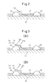
- a catalyst carrier comprised of for example alumina is carried on the NO X storing catalysts 12, 14, and FIG. 2 schematically show the cross-section of the surface part of this catalyst carrier 45.
- the catalyst carrier 45 carries a precious metal catalyst 46 diffused on its surface.
- the catalyst carrier 45 is formed with a layer of an NO X absorbent 47 on its surface.
- platinum Pt is used as the precious metal catalyst 46.
- the ingredient forming the NO X absorbent 47 for example, at least one element selected from potassium K, sodium Na, cesium Cs, or another alkali metal, barium Ba, calcium Ca, or another alkali earth, lanthanum La, yttrium Y, or another rare earth is used.
- the NO X absorbent 47 performs an NO X absorption and release action of storing the NO X when the air-fuel ratio of the exhaust gas is lean and releasing the stored NO X when the oxygen concentration in the exhaust gas falls.
- the NO X absorbent 47 when the air-fuel ratio of the exhaust gas is lean, that is, when the oxygen concentration in the exhaust gas is high, the NO contained in the exhaust gas is oxidized on the platinum Pt 46 such as shown in FIG. 2 to become NO 2 , then is absorbed in the NO X absorbent 47 and diffuses in the NO X absorbent 47 in the form of nitric acid ions NO 3 - while bonding with the barium oxide BaO. In this way, the NO X is absorbed in the NO X absorbent 47. So long as the oxygen concentration in the exhaust gas is high, NO 2 is produced on the surface of the platinum Pt 46. So long as the NO X absorbing capability of the NO X absorbent 47 is not saturated, the NO 2 is absorbed in the NO X absorbent 47 and nitric acid ions NO 3 - are produced.
- the exhaust gas contains a large amount of oxygen O 2 in addition to a reducing agent HC as shown in FIG. 3(A) . If a large amount of oxygen O 2 is contained in the exhaust gas in this way, the NO 2 or the NO released from the NO X absorbent 47 will not be reduced any further.
- the air-fuel ratio of the exhaust gas is lean as mentioned above, that is, when combustion is performed under a lean air-fuel ratio
- the NO X in the exhaust gas is absorbed in the NO X absorbent 47.
- the upstream NO X storing catalyst 12 since the upstream NO X storing catalyst 12 has a higher temperature in comparison to the downstream NO X storing catalyst 14, the upstream NO X storing catalyst 12 has a higher NO X storage ability, accordingly, NO X is absorbed more easily in the NO X absorbent 47 of the upstream NO X storing catalyst 12.
- a reducing agent is fed from the reducing agent feed valve 15 so as to temporarily make the air-fuel ratio of the exhaust gas rich and thereby make the NO X absorbent 47 release NO X .
- TC is the temperature detected by the temperature sensor 22, that is, indicates a temperature representing the temperature of the pair of NO X storing catalysts 12 and 14.
- ⁇ NOX1 indicates the stored NO X amount stored in the upstream NO X storing catalyst 12
- ⁇ NOX2 indicates the stored NO X amount stored in the downstream NO X storing catalyst 14
- A/F indicates the air-fuel ratio of the inflowing gas of the upstream NO X storing catalyst 12 which changes according to the feed of reducing agent HC from the reducing agent feed valve 15.
- the stored NO X amounts ⁇ NOX1 and ⁇ NOX2 are calculated according to the NO X amount NOXA exhausted per unit time from the combustion chamber 2, the NO X storage speed of the upstream NO X storing catalyst 12, etc.
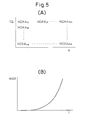
- the NO X amount NOXA exhausted per unit time from the combustion chamber 2 is stored as a function of the required torque TQ and engine speed N in the form of a map as shown in FIG. 5(A) in advance in the ROM 32.
- this exhausted NO X amount NOXA is smaller than the NO X storage speed of the upstream NO X storing catalyst 12, that is, the maximum NO X storage amount MAX that the upstream NO X storing catalyst 12 is able to store per unit time, the exhausted NO X amount NOXA becomes the NO X amount NOX1 stored per unit time in the upstream NO X storing catalyst 12.
- the stored NO X amount ⁇ NOX1 is obtained.
- the maximum NO X storage amount MAX that the upstream NO X storing catalyst 12 can store per unit time is a function of the bed temperature of the upstream NO X storing catalyst 12, the storage NO X amount ⁇ NOX1, and the exhaust gas amount, that is, the intake air amount, etc.
- the maximum NO X storage amount MAX is stored as a function of these in advance in the ROM 32.
- FIG. 5(B) shows, as an example, the relationship of the maximum NO X storage amount MAX and the bed temperature T of the upstream NO X storing catalyst 12.
- the air-fuel ratio A/F continues to be in a lean state until the time t 1 .
- the NO X storage amounts ⁇ NOX1 and ⁇ NOX2 gradually increase.
- the NO X storage amount ⁇ NOX1 of the upstream NO X storing catalyst 12 reaches the allowable value X1.
- the representative temperature TC representative of the NO X storing catalysts 12 and 14 is lower than a predetermined set temperature TX, as shown in FIG. 4 , the air-fuel ratio A/F of the exhaust gas is lowered under a lean air-fuel ratio.
- NO X is released from the upstream NO X storing catalyst 12 and this released NO X is stored in the downstream NO X storing catalyst 14. Accordingly, at this time, the NO X storage amount ⁇ NOX1 of the upstream NO X storing catalyst 12 drops, and the NOX storage amount ⁇ NOX2 of the downstream NO X storing catalyst 14 increases.
- the NO X storage amount ⁇ NOX2 of the downstream NO X storing catalyst 14 reaches the allowable value X2.
- the air-fuel ratio A/F of the exhaust gas is switched from lean to rich.
- NO X is released from the upstream NO X storing catalyst 12 and the downstream NO X storing catalyst 14, and the released NO X is reduced. Accordingly, at this time, the NO X storage amount ⁇ NOX1 of the upstream NO X storing catalyst 12 and the NO X storage amount ⁇ NOX2 of the downstream NO X storing catalyst 14 are both reduced.
- the NO X storage amount ⁇ NOX1 of the upstream NO X storing catalyst 12 reaches the allowable value X1.
- the representative temperature TC of the NO X storing catalysts 12 and 14 is higher than the predetermined set temperature TX, the air-fuel ratio A/F of the exhaust gas is switched from lean to rich as shown in FIG. 4 .
- NO X is released from the upstream NO X storing catalyst 12 and the downstream NO X storing catalyst 14, and the released NO X is reduced. Accordingly, at this time, the NO X storage amount ⁇ NOX1 of the upstream NO X storing catalyst 12 and the NO X storage amount ⁇ NOX2 of the downstream NO X storing catalyst 14 are both reduced.
- the NO X storage amount ⁇ NOX1 of the upstream NO X storing catalyst 12 once again reaches the allowable value X1.
- the representative temperature TC of the NO X storing catalysts 12 and 14 is lower than the predetermined set temperature TX, as shown in FIG. 4 , the air-fuel ratio A/F of the exhaust gas is lowered under a lean air-fuel ratio.
- NO X is released from the upstream NO X storing catalyst 12, and this released NO X is stored in the downstream NO X storing catalyst 14. Accordingly, at this time, the NO X storage amount ⁇ NOX1 of the upstream NO X storing catalyst 12 drops, and the NO X storage amount ⁇ NOX2 of the downstream NO X storing catalyst 14 increases.
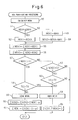
- FIG. 6 shows the purification processing routine of the NO X . This routine is executed by interruption every predetermined time period.
- step 50 the exhausted NO X amount NOXA exhausted per unit time is calculated from the map shown in FIG. 5(A) .
- step 51 it is judged if this exhausted NO X amount NOXA is smaller than the maximum NO X storage amount MAX.
- NOXA ⁇ MAX the routine proceeds to step 52, where the NO X amount NOX1 stored per unit time in the upstream NO X storing catalyst 12 is made the exhausted NO X amount NOXA.
- step 55 the routine proceeds to step 55.
- step 51 when it is judged at step 51 that NOXA>MAX, the routine proceeds to step 53, where the NO X amount NOX1 stored per unit time in the upstream NO X storing catalyst 12 is made the maximum NO X storage amount MAX.
- step 54 the routine proceeds to step 54, where the NO X amount NOX2 stored per unit time in the downstream NU X storing catalyst 14 is made the exhausted NO X amount NOXA minus the maximum NO X storage amount MAX (NOXA-MAX).
- step 55 the routine proceeds to step 55.
- NOX1 is added to the NO X amount ⁇ NOX1 stored in the upstream NO X storing catalyst 12
- NOX2 is added to the NO X amount ⁇ NOX2 stored in the downstream NO X storing catalyst 14.
- step 57 it is judged if the stored NO X amount ⁇ NOX1 of the upstream NO X storing catalyst 12 exceeds the allowable value X1.
- the routine proceeds to step 58, where it is judged if the representative temperature TC of the NO X storing catalysts 12 and 14 is higher than the predetermined set value TX.
- TX the predetermined set value
- the routine proceeds to step 59, where lean spike processing where the amount is lowered under a lean air-fuel ratio is performed.
- step 60 ⁇ NOX2 is added to ⁇ NOX1 ⁇ (0 ⁇ 1), next, at step 61, ⁇ NOX1 is made ⁇ NOX1 ⁇ (1- ⁇ ).
- step 58 when it is judged at step 58 that TC>TX, the routine proceeds to step 64, where rich spike processing where the air-fuel ratio of the exhaust gas is temporarily switched from lean to rich is performed.
- step 65 ⁇ NOX1 and ⁇ NOX2 are cleared.
- step 57 when it is judged at step 57 that ⁇ NOX1 ⁇ X1, the routine proceeds to step 62, where it is judged if the stored NO X amount ⁇ NOX2 of the downstream NO X storing catalyst 14 exceeds the allowable value X2.
- step 63 the routine proceeds to step 63, where it is judged if the representative temperature TC of the NO X storing catalysts 12 and 14 is higher than the predetermined set temperature TX.
- TC ⁇ TX the processing cycle is ended.
- the routine proceeds to step 64, where rich spike processing where the air-fuel ratio of the exhaust gas is switched from lean to rich is performed.
Landscapes
- Engineering & Computer Science (AREA)
- Chemical & Material Sciences (AREA)
- Combustion & Propulsion (AREA)
- Mechanical Engineering (AREA)
- General Engineering & Computer Science (AREA)
- Chemical Kinetics & Catalysis (AREA)
- Environmental & Geological Engineering (AREA)
- Biomedical Technology (AREA)
- Health & Medical Sciences (AREA)
- Analytical Chemistry (AREA)
- General Chemical & Material Sciences (AREA)
- Oil, Petroleum & Natural Gas (AREA)
- Exhaust Gas After Treatment (AREA)
- Exhaust Gas Treatment By Means Of Catalyst (AREA)
- Electrical Control Of Air Or Fuel Supplied To Internal-Combustion Engine (AREA)
- Combined Controls Of Internal Combustion Engines (AREA)
Abstract
Description
- The present invention relates to an exhaust purification device of an internal combustion engine.
- Known in the art is an internal combustion engine arranging in an engine exhaust passage an NOX storing catalyst which stores NOX contained in exhaust gas when the air-fuel ratio of the inflowing exhaust gas is lean and releases stored NOX when the air-fuel ratio of the inflowing exhaust gas becomes a stoichiometric air-fuel ratio or rich (see for example Japanese Patent Publication (A) No.
2004-108176 - In this way, in the past, when releasing NOX from an NOX storing catalyst, the air-fuel ratio of the NOX exhaust gas is made the stoichiometric air-fuel ratio or rich to release the NOX which is then reduced in the NOX storing catalyst. However, depending on the case, there are also cases when it is preferable for the NOX released from the NOX storing catalyst to be exhausted from the NOX storing catalyst without being reduced.
- An object of the present invention is to provide an exhaust purification device of an internal combustion engine reducing or not reducing NOX released from an NOX storing catalyst according to need.
- According to the present invention, there is provided an exhaust purification device of an internal combustion engine arranging in series in an engine exhaust passage at least a pair of NOX storing catalysts which store NOX contained in an exhaust gas when an air-fuel ratio of an inflowing exhaust gas is lean and release stored NOX when an oxygen concentration of the inflowing exhaust gas drops, the oxygen concentration of the exhaust gas being temporarily reduced while the exhaust gas is maintained at a lean air-fuel ratio when releasing NOX from an upstream NOX storing catalyst and storing the released NOX in a downstream NOX storing catalyst, the air-fuel ratio of the exhaust gas being temporarily switched from lean to rich when releasing NOX from the upstream NOX storing catalyst and the downstream NOX storing catalyst and reducing NOX.
- In the present invention, by moving the NOX stored in the upstream NOX storing catalyst, which has a comparatively high catalyst temperature and a high NOX storage ability, to the downstream NOX storing catalyst according to need, the NOX storage ability of the upstream NOX storing catalyst can be restored.
-
-
FIG. 1 is an overview of a compression ignition type internal combustion engine,FIG. 2 is a cross-sectional view of a surface portion of a catalyst carrier of an NOX storing catalyst,FIG. 3 is a cross-sectional view of a surface portion of an NOX storing catalyst,FIG. 4 is a time chart showing NOX release processing,FIG. 5 is a view showing a map etc. of the stored NOX amount NOXA, andFIG. 6 is a flowchart for executing purification processing of the NOX. -
FIG. 1 shows an overview of a compression ignition type internal combustion engine. - Referring to
FIG. 1, 1 indicates an engine body, 2 a combustion chamber of each cylinder, 3 an electronically controlled fuel injector for injecting fuel into eachcombustion chamber intake manifold 4 is connected through anintake duct 6 to the outlet of a compressor 7a of anexhaust turbocharger 7. The inlet of the compressor 7a is connected to anair cleaner 9 via an intakeair amount detector 8. Inside theintake duct 6 is arranged athrottle valve 10 driven by a step motor. Further, around theintake duct 6 is arranged acooling device 11 for cooling the intake air flowing through the inside of theintake duct 6. In the embodiment shown inFIG. 1 , the engine cooling water is guided into thecooling device 11. The engine cooling water cools the intake air. - On the other hand, the
exhaust manifold 5 is connected to the inlet of anexhaust turbine 7b of theexhaust turbocharger 7. The outlet of theexhaust turbine 7b is connected to the inlet of an upstream NOX storing catalyst 12, and the outlet of the upstream NOX storing catalyst 12 is connected to the inlet of a downstream NOX storing catalyst 14 via anexhaust pipe 13. Note that another NOX storing catalyst may be further arranged downstream of the downstream NOX storing catalyst 14. On the other hand, a reducingagent feed valve 15 for feeding a reducing agent comprised of a hydrocarbon into the exhaust gas flowing within theexhaust manifold 5 is attached to theexhaust manifold 5. - The
exhaust manifold 5 and theintake manifold 4 are interconnected through an exhaust gas recirculation (hereinafter referred to as an "EGR")passage 16, and an electronically controlledEGR control valve 17 is arranged in theEGR passage 16. Further, around the EGRpassage 16 is arranged acooling device 18 for cooling the EGR gas flowing through the inside of the EGRpassage 16. In the embodiment shown inFIG. 1 , the engine cooling water is guided into thecooling device 18. The engine cooling water cools the EGR gas. On the other hand, eachfuel injector 3 is connected through afuel feed tube 19 to acommon rail 20. Thiscommon rail 20 is supplied with fuel from an electronically controlled variabledischarge fuel pump 21. The fuel supplied into thecommon rail 20 is supplied through eachfuel feed tube 19 to thefuel injector 3. - An
electronic control unit 30 is comprised of a digital computer provided with a read only memory (ROM) 32, a random access memory (RAM) 33, a microprocessor (CPU) 34, aninput port 35, and anoutput port 36 all connected to each other by abidirectional bus 31. Atemperature sensor 22 for detecting the temperature of the exhaust gas flowing within theexhaust pipe 13 is arranged in theexhaust pipe 13. When the temperature of the exhaust gas flowing within theexhaust pipe 13 changes, the temperatures of the upstream NOX storing catalyst 12 and the downstream NOX storing catalyst 14 accordingly change and, thus, the temperature of the exhaust gas flowing within theexhaust pipe 13 represents the temperatures of a pair of the NOX storing catalysts 12, 14 arranged in series. As shown inFIG. 1 , the output signals of thetemperature sensor 22 and the intakeair amount detector 8 are input throughcorresponding AD converters 37 to theinput port 35. - An accelerator pedal 40 has a
load sensor 41 generating an output voltage proportional to the amount of depression L of the accelerator pedal 40 connected to it. The output voltage of theload sensor 41 is input through acorresponding AD converter 37 to theinput port 35. Further, theinput port 35 has acrank angle sensor 42 generating an output pulse each time the crankshaft turns for example by 15 degrees connected to it. On the other hand, theoutput port 36 is connected throughcorresponding drive circuits 38 to thefuel injectors 3, the step motor for driving thethrottle valve 10, reducingagent feed valve 15,EGR control valve 17, andfuel pump 21. - First, explaining the NOX storing catalysts 12, 14 shown in
FIG. 1 , a catalyst carrier comprised of for example alumina is carried on the NOX storing catalysts 12, 14, andFIG. 2 schematically show the cross-section of the surface part of thiscatalyst carrier 45. As shown inFIG. 2 , thecatalyst carrier 45 carries aprecious metal catalyst 46 diffused on its surface. Further, thecatalyst carrier 45 is formed with a layer of an NOX absorbent 47 on its surface. - In this embodiment of the present invention, platinum Pt is used as the
precious metal catalyst 46. As the ingredient forming the NOX absorbent 47, for example, at least one element selected from potassium K, sodium Na, cesium Cs, or another alkali metal, barium Ba, calcium Ca, or another alkali earth, lanthanum La, yttrium Y, or another rare earth is used. - If the ratio of the air and fuel (hydrocarbons) supplied to the engine intake passage,
combustion chambers 2, and exhaust passage upstream of the NOX storing catalyst 12 is referred to as the "air-fuel ratio of the exhaust gas", the NOX absorbent 47 performs an NOX absorption and release action of storing the NOX when the air-fuel ratio of the exhaust gas is lean and releasing the stored NOX when the oxygen concentration in the exhaust gas falls. - That is, if explaining this taking as an example the case of using barium Ba as the ingredient forming the NOX absorbent 47, when the air-fuel ratio of the exhaust gas is lean, that is, when the oxygen concentration in the exhaust gas is high, the NO contained in the exhaust gas is oxidized on the
platinum Pt 46 such as shown inFIG. 2 to become NO2, then is absorbed in the NOX absorbent 47 and diffuses in the NOX absorbent 47 in the form of nitric acid ions NO3 - while bonding with the barium oxide BaO. In this way, the NOX is absorbed in the NOX absorbent 47. So long as the oxygen concentration in the exhaust gas is high, NO2 is produced on the surface of theplatinum Pt 46. So long as the NOX absorbing capability of the NOX absorbent 47 is not saturated, the NO2 is absorbed in the NOX absorbent 47 and nitric acid ions NO3 - are produced. - As opposed to this, if a reducing agent is fed from the reducing
agent feed valve 15, the air-fuel ratio of the exhaust gas becomes small. At this time, since oxygen contained in the exhaust gas is consumed to oxidize the reducing agent, the oxygen concentration in the exhaust gas drops. If the oxygen concentration in the exhaust gas drops, the reaction proceeds in the reverse direction (NO3 - → NO2 or NO) as shown inFIGs. 3(A), (B) and therefore the nitric acid ions NO3 - in the NOX absorbent 47 are released from the NOX absorbent 47 in the form of NO2 or NO. Namely, if the oxygen concentration in the inflow exhaust gas drops, NOX is released from the NOX absorbent 47. - However, when lowering the air-fuel ratio of the exhaust gas while maintaining a lean air-fuel ratio of the exhaust gas and reducing the oxygen concentration of the exhaust gas, the exhaust gas contains a large amount of oxygen O2 in addition to a reducing agent HC as shown in
FIG. 3(A) . If a large amount of oxygen O2 is contained in the exhaust gas in this way, the NO2 or the NO released from the NOX absorbent 47 will not be reduced any further. - On the other hand, if the exhaust gas is made a rich air-fuel ratio, almost all of the oxygen in the exhaust gas ends up being consumed, therefore, as shown in
FIG. 3(B) , almost none of the oxygen O2 remains in the exhaust gas and therefore the reducing agent HC or CO is present in the exhaust gas. If there is a reducing agent HC or CO present in a state where there is no oxygen O2 remaining, the NO2 or NO released from the NOX absorbent 47 will be reduced down to N2. Accordingly, at this time, NOX is not exhausted from the NOX storing catalyst. - When the air-fuel ratio of the exhaust gas is lean as mentioned above, that is, when combustion is performed under a lean air-fuel ratio, the NOX in the exhaust gas is absorbed in the NOX absorbent 47. In this case, since the upstream NOX storing catalyst 12 has a higher temperature in comparison to the downstream NOX storing catalyst 14, the upstream NOX storing catalyst 12 has a higher NOX storage ability, accordingly, NOX is absorbed more easily in the NOX absorbent 47 of the upstream NOX storing catalyst 12. However, if combustion is continuously performed under a lean air-fuel ratio, the NOX absorption ability of the NOX absorbent 47 eventually ends up becoming saturated, and, therefore, the NOX absorbent 47 becomes unable to absorb NOX any longer Therefore, in the embodiment according to the present invention, before the NOX absorbent 47 becomes saturated in absorption ability, a reducing agent is fed from the reducing
agent feed valve 15 so as to temporarily make the air-fuel ratio of the exhaust gas rich and thereby make the NOX absorbent 47 release NOX. - In this regard, when the temperature of the NOX storing catalyst is low and the
catalyst 46 is not activated sufficiently, if a large amount of reducing agent HC is fed from the reducingagent feed valve 15 to make the air-fuel ratio of the exhaust gas rich, a problem occurs in that a considerable amount of reducing agent HC is exhausted into the atmosphere because the reducing agent HC is not reduced sufficiently. Therefore, in the present invention, when the temperatures of the NOX storing catalysts 12 and 14 are low and thecatalyst 46 is not activated sufficiently, only an amount of reducing agent that is able to be oxidized is fed. At this time, the oxygen concentration in the exhaust gas drops while the exhaust gas is maintained at a lean air-fuel ratio, therefore, as seen fromFIG. 3(A) , NO2 or NO is exhausted from the upstream NOX storing catalyst 12 and this NO2 or NO is stored in the downstream NOX storing catalyst 14. - Next, this will be explained while referring to
FIG. 4 . Note that, inFIG. 4 , TC is the temperature detected by thetemperature sensor 22, that is, indicates a temperature representing the temperature of the pair of NOX storingcatalysts agent feed valve 15. - In the embodiment according to the present invention, the stored NOX amounts ΣNOX1 and ΣNOX2 are calculated according to the NOX amount NOXA exhausted per unit time from the
combustion chamber 2, the NOX storage speed of the upstream NOX storing catalyst 12, etc. Here, the NOX amount NOXA exhausted per unit time from thecombustion chamber 2 is stored as a function of the required torque TQ and engine speed N in the form of a map as shown inFIG. 5(A) in advance in theROM 32. If this exhausted NOX amount NOXA is smaller than the NOX storage speed of the upstream NOX storing catalyst 12, that is, the maximum NOX storage amount MAX that the upstream NOX storing catalyst 12 is able to store per unit time, the exhausted NOX amount NOXA becomes the NOX amount NOX1 stored per unit time in the upstream NOX storing catalyst 12. By cumulatively adding these NOX amounts NOX1, the stored NOX amount ΣNOX1 is obtained. - As opposed to this, if the exhausted NOX amount NOXA is larger than the NOX storage speed of the upstream NOX storing catalyst 12, that is, the maximum NOX storage amount MAX that the upstream NOX storing catalyst 12 is able to store per unit time, this maximum NOX storage amount MAX becomes the NOX amount NOX1 stored per unit time in the upstream NOX storing catalyst 12. At this time, the surplus NOX amount (NOXA-MAX) that was not stored in the upstream NOX storing catalyst 12 becomes the NOX amount NOX2 stored per unit time in the downstream NOX storing catalyst 14. By cumulatively adding these NOX amounts NOX2, the stored NOX amount ΣNOX2 is obtained.
- Note that, the maximum NOX storage amount MAX that the upstream NOX storing catalyst 12 can store per unit time is a function of the bed temperature of the upstream NOX storing catalyst 12, the storage NOX amount ΣNOX1, and the exhaust gas amount, that is, the intake air amount, etc. The maximum NOX storage amount MAX is stored as a function of these in advance in the
ROM 32. Note that,FIG. 5(B) shows, as an example, the relationship of the maximum NOX storage amount MAX and the bed temperature T of the upstream NOX storing catalyst 12. - As shown in
FIG. 4 , the air-fuel ratio A/F continues to be in a lean state until the time t1. In this period, the NOX storage amounts ΣNOX1 and ΣNOX2 gradually increase. Next, at the time t1, the NOX storage amount ΣNOX1 of the upstream NOX storing catalyst 12 reaches the allowable value X1. At this time, if the representative temperature TC representative of the NOX storing catalysts 12 and 14 is lower than a predetermined set temperature TX, as shown inFIG. 4 , the air-fuel ratio A/F of the exhaust gas is lowered under a lean air-fuel ratio. At this time, NOX is released from the upstream NOX storing catalyst 12 and this released NOX is stored in the downstream NOX storing catalyst 14. Accordingly, at this time, the NOX storage amount ΣNOX1 of the upstream NOX storing catalyst 12 drops, and the NOX storage amount ΣNOX2 of the downstream NOX storing catalyst 14 increases. - Next, assume that, at the time t2, the NOX storage amount ΣNOX2 of the downstream NOX storing catalyst 14 reaches the allowable value X2. At this time, if assuming the representative temperature TC of the NOX storing catalysts 12 and 14 is higher than the predetermined set temperature TX, as shown in
FIG. 4 , the air-fuel ratio A/F of the exhaust gas is switched from lean to rich. At this time, NOX is released from the upstream NOX storing catalyst 12 and the downstream NOX storing catalyst 14, and the released NOX is reduced. Accordingly, at this time, the NOX storage amount ΣNOX1 of the upstream NOX storing catalyst 12 and the NOX storage amount ΣNOX2 of the downstream NOX storing catalyst 14 are both reduced. - Next, assume that, at the time t3, the NOX storage amount ΣNOX1 of the upstream NOX storing catalyst 12 reaches the allowable value X1. At this time, if the representative temperature TC of the NOX storing catalysts 12 and 14 is higher than the predetermined set temperature TX, the air-fuel ratio A/F of the exhaust gas is switched from lean to rich as shown in
FIG. 4 . At this time, NOX is released from the upstream NOX storing catalyst 12 and the downstream NOX storing catalyst 14, and the released NOX is reduced. Accordingly, at this time, the NOX storage amount ΣNOX1 of the upstream NOX storing catalyst 12 and the NOX storage amount ΣNOX2 of the downstream NOX storing catalyst 14 are both reduced. - Next, assume that, at the time t4, the NOX storage amount ΣNOX1 of the upstream NOX storing catalyst 12 once again reaches the allowable value X1. At this time, if the representative temperature TC of the NOX storing catalysts 12 and 14 is lower than the predetermined set temperature TX, as shown in
FIG. 4 , the air-fuel ratio A/F of the exhaust gas is lowered under a lean air-fuel ratio. At this time, NOX is released from the upstream NOX storing catalyst 12, and this released NOX is stored in the downstream NOX storing catalyst 14. Accordingly, at this time, the NOX storage amount ΣNOX1 of the upstream NOX storing catalyst 12 drops, and the NOX storage amount ΣNOX2 of the downstream NOX storing catalyst 14 increases. -
FIG. 6 shows the purification processing routine of the NOX. This routine is executed by interruption every predetermined time period. - Referring to
FIG. 6 , first, atstep 50, the exhausted NOX amount NOXA exhausted per unit time is calculated from the map shown inFIG. 5(A) . Next, atstep 51, it is judged if this exhausted NOX amount NOXA is smaller than the maximum NOX storage amount MAX. When NOXA≤MAX, the routine proceeds to step 52, where the NOX amount NOX1 stored per unit time in the upstream NOX storing catalyst 12 is made the exhausted NOX amount NOXA. Next, the routine proceeds to step 55. - As opposed to this, when it is judged at
step 51 that NOXA>MAX, the routine proceeds to step 53, where the NOX amount NOX1 stored per unit time in the upstream NOX storing catalyst 12 is made the maximum NOX storage amount MAX. Next, the routine proceeds to step 54, where the NOX amount NOX2 stored per unit time in the downstream NUX storing catalyst 14 is made the exhausted NOX amount NOXA minus the maximum NOX storage amount MAX (NOXA-MAX). Next, the routine proceeds to step 55. Atstep 55, NOX1 is added to the NOX amount ΣNOX1 stored in the upstream NOX storing catalyst 12, next atstep 56, NOX2 is added to the NOX amount ΣNOX2 stored in the downstream NOX storing catalyst 14. - Next, at
step 57, it is judged if the stored NOX amount ΣNOX1 of the upstream NOX storing catalyst 12 exceeds the allowable value X1. When ΣNOX1>X1, the routine proceeds to step 58, where it is judged if the representative temperature TC of the NOX storing catalysts 12 and 14 is higher than the predetermined set value TX. When TC≤TX, the routine proceeds to step 59, where lean spike processing where the amount is lowered under a lean air-fuel ratio is performed. Next, atstep 60, ΣNOX2 is added to ΣNOX1·α(0<α≤1), next, atstep 61, ΣNOX1 is made ΣNOX1·(1-α). As opposed to this, when it is judged atstep 58 that TC>TX, the routine proceeds to step 64,
where rich spike processing where the air-fuel ratio of the exhaust gas is temporarily switched from lean to rich is performed. Next, atstep 65, ΣNOX1 and ΣNOX2 are cleared. - On the other hand, when it is judged at
step 57 that ΣNOX1≤X1, the routine proceeds to step 62, where it is judged if the stored NOX amount ΣNOX2 of the downstream NOX storing catalyst 14 exceeds the allowable value X2. When ΣNOX2>X2, the routine proceeds to step 63, where it is judged if the representative temperature TC of the NOX storing catalysts 12 and 14 is higher than the predetermined set temperature TX. When TC≤TX, the processing cycle is ended. As opposed to this, when TC>TX, the routine proceeds to step 64, where rich spike processing where the air-fuel ratio of the exhaust gas is switched from lean to rich is performed. -
- 4... intake manifold
- 5... exhaust manifold
- 7... exhaust turbocharger
- 12... upstream NOX storage catalyst
- 14... downstream NOX storage catalyst
- 15... reducing agent feed valve
Claims (4)
- An exhaust purification device of an internal combustion arranging in series in an engine exhaust passage at least a pair of NOX storing catalysts which store NOX contained in an exhaust gas when an air-fuel ratio of an inflowing exhaust gas is lean and release stored NOX when an oxygen concentration of the inflowing exhaust gas drops, the oxygen concentration of the exhaust gas being temporarily reduced while the exhaust gas is maintained at a lean air-fuel ratio when releasing NOX from an upstream NOX storing catalyst and storing the released NOX in a downstream NOX storing catalyst, the air-fuel ratio of the exhaust gas being temporarily switched from lean to rich when releasing NOX from the upstream NOX storing catalyst and the downstream NOX storing catalyst and reducing NOX.
- An exhaust purification device of an internal combustion engine as claimed in claim 1, wherein when an NOX amount stored in the upstream NOX storing catalyst exceeds an allowable amount, if a temperature representing temperatures of the pair of NOX storing catalysts is lower than a predetermined set temperature, the oxygen concentration in the exhaust gas is temporarily lowered while maintaining the exhaust gas at a lean air-fuel ratio to thereby cause the upstream NOX storing catalyst to release the NOX and store the released NOX in the downstream NOX storing catalyst, and when the NOX amount stored in the upstream NOX storing catalyst exceeds the allowable amount, if the temperature representing the temperatures of the pair of NOX storing catalysts is higher than the predetermined set temperature, the air-fuel ratio of the exhaust gas is temporarily switched from lean to rich to thereby cause the upstream NOX storing catalyst and the downstream NOX storing catalyst to release the NOX and reduce the NOX.
- An exhaust purification device of an internal combustion engine as claimed in claim 1, wherein when an NOX amount stored in the downstream NOX storing catalyst exceeds an allowable amount, if the temperature representing the temperatures of the pair of NOX storing catalysts is greater than a predetermined set temperature, the air-fuel ratio of the exhaust gas is temporarily switched from lean to rich to thereby cause the upstream NOX storing catalyst and downstream NOX storing catalyst to release the NOX and reduce the NOX.
- An exhaust purification device of an internal combustion engine as claimed in claim 1, wherein a reducing agent feed valve for feeding a reducing agent comprised of a hydrocarbon is arranged inside the engine exhaust passage upstream of the NOX storing catalyst, and the oxygen concentration of the exhaust gas is lowered by feeding the hydrocarbon from the reducing agent feed valve.
Applications Claiming Priority (2)
| Application Number | Priority Date | Filing Date | Title |
|---|---|---|---|
| JP2007072156A JP4420048B2 (en) | 2007-03-20 | 2007-03-20 | Exhaust gas purification device for internal combustion engine |
| PCT/JP2008/055796 WO2008114887A1 (en) | 2007-03-20 | 2008-03-19 | Exhaust cleaner for internal combustion engine |
Publications (3)
| Publication Number | Publication Date |
|---|---|
| EP2138692A1 true EP2138692A1 (en) | 2009-12-30 |
| EP2138692A4 EP2138692A4 (en) | 2011-08-31 |
| EP2138692B1 EP2138692B1 (en) | 2014-11-12 |
Family
ID=39765985
Family Applications (1)
| Application Number | Title | Priority Date | Filing Date |
|---|---|---|---|
| EP08738963.1A Not-in-force EP2138692B1 (en) | 2007-03-20 | 2008-03-19 | Exhaust cleaner for internal combustion engine |
Country Status (5)
| Country | Link |
|---|---|
| US (1) | US8297044B2 (en) |
| EP (1) | EP2138692B1 (en) |
| JP (1) | JP4420048B2 (en) |
| CN (1) | CN101646852B (en) |
| WO (1) | WO2008114887A1 (en) |
Families Citing this family (32)
| Publication number | Priority date | Publication date | Assignee | Title |
|---|---|---|---|---|
| JP4868096B2 (en) * | 2009-09-03 | 2012-02-01 | トヨタ自動車株式会社 | Exhaust gas purification device for internal combustion engine |
| JPWO2011048706A1 (en) * | 2009-10-23 | 2013-03-07 | トヨタ自動車株式会社 | Air-fuel ratio control device for internal combustion engine |
| KR101383422B1 (en) | 2010-03-15 | 2014-04-08 | 도요타지도샤가부시키가이샤 | Exhaust purification system of internal combustion engine |
| ES2508365T3 (en) * | 2010-03-15 | 2014-10-16 | Toyota Jidosha Kabushiki Kaisha | Method of operation of an exhaust gas purification system of an internal combustion engine |
| CN102782268B (en) * | 2010-03-15 | 2015-04-15 | 丰田自动车株式会社 | Exhaust purification device for internal combustion engines |
| JP5196027B2 (en) | 2010-04-01 | 2013-05-15 | トヨタ自動車株式会社 | Exhaust gas purification device for internal combustion engine |
| WO2012014330A1 (en) | 2010-07-28 | 2012-02-02 | トヨタ自動車株式会社 | Exhaust purification apparatus for internal combustion engine |
| CN103003539B (en) | 2010-08-30 | 2015-03-18 | 丰田自动车株式会社 | Exhaust gas purification device for internal combustion engine |
| EP2460990B8 (en) | 2010-08-30 | 2016-12-07 | Toyota Jidosha Kabushiki Kaisha | Exhaust gas purification device for internal combustion engine |
| US8833056B2 (en) | 2010-09-02 | 2014-09-16 | Toyota Jidosha Kabushiki Kaisha | Exhaust purification system of internal combustion engine |
| US8656706B2 (en) | 2010-09-02 | 2014-02-25 | Toyota Jidosha Kabushiki Kaisha | Exhaust purification system of internal combustion engine |
| US9034267B2 (en) | 2010-10-04 | 2015-05-19 | Toyota Jidosha Kabushiki Kaisha | Exhaust purification system of internal combustion engine |
| EP2472078B1 (en) | 2010-10-04 | 2018-05-16 | Toyota Jidosha Kabushiki Kaisha | An exhaust purification system of an internal combustion engine |
| WO2012053117A1 (en) | 2010-10-18 | 2012-04-26 | トヨタ自動車株式会社 | Exhaust gas purification device for internal combustion engine |
| WO2012077240A1 (en) | 2010-12-06 | 2012-06-14 | トヨタ自動車株式会社 | Exhaust gas purification device for internal combustion engine |
| BRPI1010835B8 (en) | 2010-12-20 | 2021-01-12 | Toyota Motor Co Ltd | internal combustion engine exhaust purification system |
| ES2629430T3 (en) | 2010-12-24 | 2017-08-09 | Toyota Jidosha Kabushiki Kaisha | Exhaust gas purification system for internal combustion engine |
| WO2012108059A1 (en) | 2011-02-07 | 2012-08-16 | トヨタ自動車株式会社 | Exhaust-gas purifying device for internal-combustion engine |
| JP5131394B2 (en) | 2011-02-10 | 2013-01-30 | トヨタ自動車株式会社 | Exhaust gas purification device for internal combustion engine |
| WO2012124173A1 (en) | 2011-03-17 | 2012-09-20 | トヨタ自動車株式会社 | Internal combustion engine exhaust gas purification device |
| WO2012140784A1 (en) | 2011-04-15 | 2012-10-18 | トヨタ自動車株式会社 | Exhaust cleaner for internal combustion engine |
| JP5742535B2 (en) * | 2011-07-20 | 2015-07-01 | 日産自動車株式会社 | Intake collector internal state estimation device |
| CN103998731B (en) | 2011-11-07 | 2016-11-16 | 丰田自动车株式会社 | The emission-control equipment of internal combustion engine |
| US9097157B2 (en) | 2011-11-09 | 2015-08-04 | Toyota Jidosha Kabushiki Kaisha | Exhaust purification system of internal combustion engine |
| WO2013080328A1 (en) | 2011-11-30 | 2013-06-06 | トヨタ自動車株式会社 | Exhaust purification device for internal combustion engine |
| JP5273304B1 (en) | 2011-11-30 | 2013-08-28 | トヨタ自動車株式会社 | Exhaust gas purification device for internal combustion engine |
| ES2629482T3 (en) | 2012-02-07 | 2017-08-10 | Toyota Jidosha Kabushiki Kaisha | Exhaust gas purification device for internal combustion engine |
| JP6015629B2 (en) * | 2013-11-01 | 2016-10-26 | トヨタ自動車株式会社 | Control device for internal combustion engine |
| JP6477088B2 (en) * | 2015-03-20 | 2019-03-06 | いすゞ自動車株式会社 | NOx storage amount estimation device |
| US10323594B2 (en) | 2016-06-17 | 2019-06-18 | Ford Global Technologies, Llc | Methods and systems for treating vehicle emissions |
| JP6733651B2 (en) * | 2017-12-27 | 2020-08-05 | トヨタ自動車株式会社 | Exhaust gas purification device for internal combustion engine |
| JP2019152167A (en) * | 2018-03-05 | 2019-09-12 | トヨタ自動車株式会社 | Exhaust emission control device for internal combustion engine |
Family Cites Families (19)
| Publication number | Priority date | Publication date | Assignee | Title |
|---|---|---|---|---|
| JP2783074B2 (en) * | 1991-10-29 | 1998-08-06 | トヨタ自動車株式会社 | Exhaust gas purification device for internal combustion engine |
| JP3344040B2 (en) * | 1993-11-25 | 2002-11-11 | トヨタ自動車株式会社 | Exhaust gas purification device for internal combustion engine |
| JP3484759B2 (en) * | 1994-05-18 | 2004-01-06 | いすゞ自動車株式会社 | Diesel engine exhaust purification system |
| US6718756B1 (en) * | 1999-01-21 | 2004-04-13 | Mitsubishi Jidosha Kogyo Kabushiki Kaisha | Exhaust gas purifier for use in internal combustion engine |
| JP3536713B2 (en) | 1999-03-05 | 2004-06-14 | トヨタ自動車株式会社 | Exhaust gas purification device for internal combustion engine |
| DE19918756A1 (en) | 1999-04-24 | 2000-10-26 | Volkswagen Ag | Exhaust catalyst system includes three-way catalyst removing reductants carbon monoxide and hydrocarbons, followed by two nitrogen oxide storage catalysts optimized for operation at different temperatures |
| JP3733834B2 (en) | 2000-05-02 | 2006-01-11 | 日産自動車株式会社 | Exhaust gas purification device for internal combustion engine |
| JP3617450B2 (en) * | 2000-12-20 | 2005-02-02 | トヨタ自動車株式会社 | Exhaust gas purification device for internal combustion engine |
| JP3636116B2 (en) * | 2001-03-21 | 2005-04-06 | 日産自動車株式会社 | Exhaust gas purification device for internal combustion engine |
| JP3632614B2 (en) * | 2001-05-11 | 2005-03-23 | 日産自動車株式会社 | Exhaust gas purification device for internal combustion engine |
| JP2003049681A (en) * | 2001-08-07 | 2003-02-21 | Toyota Motor Corp | Exhaust purification device for internal combustion engine |
| JP3828425B2 (en) * | 2002-01-08 | 2006-10-04 | 三菱電機株式会社 | Exhaust gas purification method for internal combustion engine |
| JP4045803B2 (en) | 2002-01-09 | 2008-02-13 | トヨタ自動車株式会社 | Method and apparatus for reducing exhaust purification catalyst of internal combustion engine |
| JP4167871B2 (en) | 2002-09-13 | 2008-10-22 | トヨタ自動車株式会社 | Exhaust gas purification device for internal combustion engine |
| DE10308288B4 (en) | 2003-02-26 | 2006-09-28 | Umicore Ag & Co. Kg | Process for the removal of nitrogen oxides from the exhaust gas of a lean-burned internal combustion engine and exhaust gas purification system for this purpose |
| GB0305415D0 (en) | 2003-03-08 | 2003-04-16 | Johnson Matthey Plc | Exhaust system for lean burn IC engine including particulate filter and NOx absorbent |
| US6938412B2 (en) * | 2003-08-07 | 2005-09-06 | General Motors Corporation | Removing nitrogen oxides during a lean-burn engine cold start |
| JP4020054B2 (en) * | 2003-09-24 | 2007-12-12 | トヨタ自動車株式会社 | Exhaust gas purification system for internal combustion engine |
| JP2005291098A (en) * | 2004-03-31 | 2005-10-20 | Mitsubishi Fuso Truck & Bus Corp | Exhaust emission control device for engine |
-
2007
- 2007-03-20 JP JP2007072156A patent/JP4420048B2/en not_active Expired - Fee Related
-
2008
- 2008-03-19 EP EP08738963.1A patent/EP2138692B1/en not_active Not-in-force
- 2008-03-19 US US12/449,972 patent/US8297044B2/en not_active Expired - Fee Related
- 2008-03-19 CN CN2008800077684A patent/CN101646852B/en not_active Expired - Fee Related
- 2008-03-19 WO PCT/JP2008/055796 patent/WO2008114887A1/en not_active Ceased
Also Published As
| Publication number | Publication date |
|---|---|
| EP2138692A4 (en) | 2011-08-31 |
| JP2008232003A (en) | 2008-10-02 |
| CN101646852A (en) | 2010-02-10 |
| EP2138692B1 (en) | 2014-11-12 |
| US8297044B2 (en) | 2012-10-30 |
| WO2008114887A1 (en) | 2008-09-25 |
| US20100115923A1 (en) | 2010-05-13 |
| JP4420048B2 (en) | 2010-02-24 |
| CN101646852B (en) | 2013-11-13 |
Similar Documents
| Publication | Publication Date | Title |
|---|---|---|
| EP2138692B1 (en) | Exhaust cleaner for internal combustion engine | |
| EP1685311B1 (en) | Exhaust purification device of compression ignition type internal combustion engine | |
| EP2199555B1 (en) | Exhaust gas purification apparatus for internal combustion engine | |
| US20090049825A1 (en) | Exhaust Gas Purification Device For Internal Combustion Engine | |
| EP2175113B1 (en) | Exhaust gas purification apparatus for internal combustion engine | |
| EP2063077B1 (en) | Exhaust purification device for internal combustion engine | |
| US8051647B2 (en) | Exhaust purification device of internal combustion engine | |
| EP2420655B1 (en) | Exhaust purification device for internal combustion engine | |
| WO2008102915A1 (en) | Exhaust purification device of internal combustion engine | |
| US20080302090A1 (en) | Exhaust purification device of internal combustion engine | |
| EP2133528B1 (en) | Exhaust purification device for internal combustion engine | |
| EP2282024B1 (en) | Exhaust purifying device for internal combustion engine | |
| JP5206597B2 (en) | Exhaust gas purification device for internal combustion engine | |
| EP2280156B1 (en) | Exhaust purifying device for internal combustion engine | |
| EP2395210A1 (en) | Exhaust cleaning device for internal combustion engine |
Legal Events
| Date | Code | Title | Description |
|---|---|---|---|
| PUAI | Public reference made under article 153(3) epc to a published international application that has entered the european phase |
Free format text: ORIGINAL CODE: 0009012 |
|
| 17P | Request for examination filed |
Effective date: 20091020 |
|
| AK | Designated contracting states |
Kind code of ref document: A1 Designated state(s): AT BE BG CH CY CZ DE DK EE ES FI FR GB GR HR HU IE IS IT LI LT LU LV MC MT NL NO PL PT RO SE SI SK TR |
|
| DAX | Request for extension of the european patent (deleted) | ||
| A4 | Supplementary search report drawn up and despatched |
Effective date: 20110802 |
|
| RIC1 | Information provided on ipc code assigned before grant |
Ipc: F01N 3/28 20060101ALI20110727BHEP Ipc: F02D 45/00 20060101ALI20110727BHEP Ipc: F02D 43/00 20060101ALI20110727BHEP Ipc: B01D 53/86 20060101ALI20110727BHEP Ipc: F01N 3/08 20060101ALI20110727BHEP Ipc: B01D 53/94 20060101ALI20110727BHEP Ipc: F02D 41/04 20060101AFI20110727BHEP |
|
| 17Q | First examination report despatched |
Effective date: 20120418 |
|
| RAP1 | Party data changed (applicant data changed or rights of an application transferred) |
Owner name: TOYOTA JIDOSHA KABUSHIKI KAISHA |
|
| GRAP | Despatch of communication of intention to grant a patent |
Free format text: ORIGINAL CODE: EPIDOSNIGR1 |
|
| INTG | Intention to grant announced |
Effective date: 20140526 |
|
| RIN1 | Information on inventor provided before grant (corrected) |
Inventor name: TSUJIMOTO, KENICHI Inventor name: HIROTA, SHINYA |
|
| INTG | Intention to grant announced |
Effective date: 20140603 |
|
| GRAS | Grant fee paid |
Free format text: ORIGINAL CODE: EPIDOSNIGR3 |
|
| GRAA | (expected) grant |
Free format text: ORIGINAL CODE: 0009210 |
|
| AK | Designated contracting states |
Kind code of ref document: B1 Designated state(s): AT BE BG CH CY CZ DE DK EE ES FI FR GB GR HR HU IE IS IT LI LT LU LV MC MT NL NO PL PT RO SE SI SK TR |
|
| REG | Reference to a national code |
Ref country code: GB Ref legal event code: FG4D |
|
| REG | Reference to a national code |
Ref country code: CH Ref legal event code: EP |
|
| REG | Reference to a national code |
Ref country code: AT Ref legal event code: REF Ref document number: 695923 Country of ref document: AT Kind code of ref document: T Effective date: 20141115 |
|
| REG | Reference to a national code |
Ref country code: IE Ref legal event code: FG4D |
|
| REG | Reference to a national code |
Ref country code: DE Ref legal event code: R096 Ref document number: 602008035308 Country of ref document: DE Effective date: 20141224 |
|
| REG | Reference to a national code |
Ref country code: DE Ref legal event code: R084 Ref document number: 602008035308 Country of ref document: DE |
|
| REG | Reference to a national code |
Ref country code: DE Ref legal event code: R084 Ref document number: 602008035308 Country of ref document: DE Effective date: 20150113 |
|
| REG | Reference to a national code |
Ref country code: FR Ref legal event code: PLFP Year of fee payment: 8 |
|
| REG | Reference to a national code |
Ref country code: NL Ref legal event code: VDEP Effective date: 20141112 |
|
| REG | Reference to a national code |
Ref country code: AT Ref legal event code: MK05 Ref document number: 695923 Country of ref document: AT Kind code of ref document: T Effective date: 20141112 |
|
| PG25 | Lapsed in a contracting state [announced via postgrant information from national office to epo] |
Ref country code: PT Free format text: LAPSE BECAUSE OF FAILURE TO SUBMIT A TRANSLATION OF THE DESCRIPTION OR TO PAY THE FEE WITHIN THE PRESCRIBED TIME-LIMIT Effective date: 20150312 Ref country code: LT Free format text: LAPSE BECAUSE OF FAILURE TO SUBMIT A TRANSLATION OF THE DESCRIPTION OR TO PAY THE FEE WITHIN THE PRESCRIBED TIME-LIMIT Effective date: 20141112 Ref country code: NO Free format text: LAPSE BECAUSE OF FAILURE TO SUBMIT A TRANSLATION OF THE DESCRIPTION OR TO PAY THE FEE WITHIN THE PRESCRIBED TIME-LIMIT Effective date: 20150212 Ref country code: ES Free format text: LAPSE BECAUSE OF FAILURE TO SUBMIT A TRANSLATION OF THE DESCRIPTION OR TO PAY THE FEE WITHIN THE PRESCRIBED TIME-LIMIT Effective date: 20141112 Ref country code: NL Free format text: LAPSE BECAUSE OF FAILURE TO SUBMIT A TRANSLATION OF THE DESCRIPTION OR TO PAY THE FEE WITHIN THE PRESCRIBED TIME-LIMIT Effective date: 20141112 Ref country code: IS Free format text: LAPSE BECAUSE OF FAILURE TO SUBMIT A TRANSLATION OF THE DESCRIPTION OR TO PAY THE FEE WITHIN THE PRESCRIBED TIME-LIMIT Effective date: 20150312 Ref country code: FI Free format text: LAPSE BECAUSE OF FAILURE TO SUBMIT A TRANSLATION OF THE DESCRIPTION OR TO PAY THE FEE WITHIN THE PRESCRIBED TIME-LIMIT Effective date: 20141112 |
|
| PGFP | Annual fee paid to national office [announced via postgrant information from national office to epo] |
Ref country code: DE Payment date: 20150310 Year of fee payment: 8 |
|
| PG25 | Lapsed in a contracting state [announced via postgrant information from national office to epo] |
Ref country code: PL Free format text: LAPSE BECAUSE OF FAILURE TO SUBMIT A TRANSLATION OF THE DESCRIPTION OR TO PAY THE FEE WITHIN THE PRESCRIBED TIME-LIMIT Effective date: 20141112 Ref country code: GR Free format text: LAPSE BECAUSE OF FAILURE TO SUBMIT A TRANSLATION OF THE DESCRIPTION OR TO PAY THE FEE WITHIN THE PRESCRIBED TIME-LIMIT Effective date: 20150213 Ref country code: LV Free format text: LAPSE BECAUSE OF FAILURE TO SUBMIT A TRANSLATION OF THE DESCRIPTION OR TO PAY THE FEE WITHIN THE PRESCRIBED TIME-LIMIT Effective date: 20141112 Ref country code: SE Free format text: LAPSE BECAUSE OF FAILURE TO SUBMIT A TRANSLATION OF THE DESCRIPTION OR TO PAY THE FEE WITHIN THE PRESCRIBED TIME-LIMIT Effective date: 20141112 Ref country code: HR Free format text: LAPSE BECAUSE OF FAILURE TO SUBMIT A TRANSLATION OF THE DESCRIPTION OR TO PAY THE FEE WITHIN THE PRESCRIBED TIME-LIMIT Effective date: 20141112 Ref country code: CY Free format text: LAPSE BECAUSE OF FAILURE TO SUBMIT A TRANSLATION OF THE DESCRIPTION OR TO PAY THE FEE WITHIN THE PRESCRIBED TIME-LIMIT Effective date: 20141112 Ref country code: AT Free format text: LAPSE BECAUSE OF FAILURE TO SUBMIT A TRANSLATION OF THE DESCRIPTION OR TO PAY THE FEE WITHIN THE PRESCRIBED TIME-LIMIT Effective date: 20141112 |
|
| PGFP | Annual fee paid to national office [announced via postgrant information from national office to epo] |
Ref country code: FR Payment date: 20150309 Year of fee payment: 8 |
|
| PG25 | Lapsed in a contracting state [announced via postgrant information from national office to epo] |
Ref country code: DK Free format text: LAPSE BECAUSE OF FAILURE TO SUBMIT A TRANSLATION OF THE DESCRIPTION OR TO PAY THE FEE WITHIN THE PRESCRIBED TIME-LIMIT Effective date: 20141112 Ref country code: CZ Free format text: LAPSE BECAUSE OF FAILURE TO SUBMIT A TRANSLATION OF THE DESCRIPTION OR TO PAY THE FEE WITHIN THE PRESCRIBED TIME-LIMIT Effective date: 20141112 Ref country code: EE Free format text: LAPSE BECAUSE OF FAILURE TO SUBMIT A TRANSLATION OF THE DESCRIPTION OR TO PAY THE FEE WITHIN THE PRESCRIBED TIME-LIMIT Effective date: 20141112 Ref country code: SK Free format text: LAPSE BECAUSE OF FAILURE TO SUBMIT A TRANSLATION OF THE DESCRIPTION OR TO PAY THE FEE WITHIN THE PRESCRIBED TIME-LIMIT Effective date: 20141112 Ref country code: RO Free format text: LAPSE BECAUSE OF FAILURE TO SUBMIT A TRANSLATION OF THE DESCRIPTION OR TO PAY THE FEE WITHIN THE PRESCRIBED TIME-LIMIT Effective date: 20141112 |
|
| REG | Reference to a national code |
Ref country code: DE Ref legal event code: R097 Ref document number: 602008035308 Country of ref document: DE |
|
| PLBE | No opposition filed within time limit |
Free format text: ORIGINAL CODE: 0009261 |
|
| STAA | Information on the status of an ep patent application or granted ep patent |
Free format text: STATUS: NO OPPOSITION FILED WITHIN TIME LIMIT |
|
| 26N | No opposition filed |
Effective date: 20150813 |
|
| PG25 | Lapsed in a contracting state [announced via postgrant information from national office to epo] |
Ref country code: MC Free format text: LAPSE BECAUSE OF FAILURE TO SUBMIT A TRANSLATION OF THE DESCRIPTION OR TO PAY THE FEE WITHIN THE PRESCRIBED TIME-LIMIT Effective date: 20141112 Ref country code: LU Free format text: LAPSE BECAUSE OF FAILURE TO SUBMIT A TRANSLATION OF THE DESCRIPTION OR TO PAY THE FEE WITHIN THE PRESCRIBED TIME-LIMIT Effective date: 20150319 |
|
| REG | Reference to a national code |
Ref country code: CH Ref legal event code: PL |
|
| GBPC | Gb: european patent ceased through non-payment of renewal fee |
Effective date: 20150319 |
|
| PG25 | Lapsed in a contracting state [announced via postgrant information from national office to epo] |
Ref country code: IT Free format text: LAPSE BECAUSE OF FAILURE TO SUBMIT A TRANSLATION OF THE DESCRIPTION OR TO PAY THE FEE WITHIN THE PRESCRIBED TIME-LIMIT Effective date: 20141112 |
|
| REG | Reference to a national code |
Ref country code: IE Ref legal event code: MM4A |
|
| PG25 | Lapsed in a contracting state [announced via postgrant information from national office to epo] |
Ref country code: CH Free format text: LAPSE BECAUSE OF NON-PAYMENT OF DUE FEES Effective date: 20150331 Ref country code: IE Free format text: LAPSE BECAUSE OF NON-PAYMENT OF DUE FEES Effective date: 20150319 Ref country code: LI Free format text: LAPSE BECAUSE OF NON-PAYMENT OF DUE FEES Effective date: 20150331 Ref country code: GB Free format text: LAPSE BECAUSE OF NON-PAYMENT OF DUE FEES Effective date: 20150319 |
|
| PG25 | Lapsed in a contracting state [announced via postgrant information from national office to epo] |
Ref country code: SI Free format text: LAPSE BECAUSE OF FAILURE TO SUBMIT A TRANSLATION OF THE DESCRIPTION OR TO PAY THE FEE WITHIN THE PRESCRIBED TIME-LIMIT Effective date: 20141112 |
|
| REG | Reference to a national code |
Ref country code: DE Ref legal event code: R119 Ref document number: 602008035308 Country of ref document: DE |
|
| PG25 | Lapsed in a contracting state [announced via postgrant information from national office to epo] |
Ref country code: MT Free format text: LAPSE BECAUSE OF FAILURE TO SUBMIT A TRANSLATION OF THE DESCRIPTION OR TO PAY THE FEE WITHIN THE PRESCRIBED TIME-LIMIT Effective date: 20141112 |
|
| REG | Reference to a national code |
Ref country code: FR Ref legal event code: ST Effective date: 20161130 |
|
| PG25 | Lapsed in a contracting state [announced via postgrant information from national office to epo] |
Ref country code: FR Free format text: LAPSE BECAUSE OF NON-PAYMENT OF DUE FEES Effective date: 20160331 Ref country code: DE Free format text: LAPSE BECAUSE OF NON-PAYMENT OF DUE FEES Effective date: 20161001 |
|
| PG25 | Lapsed in a contracting state [announced via postgrant information from national office to epo] |
Ref country code: BG Free format text: LAPSE BECAUSE OF FAILURE TO SUBMIT A TRANSLATION OF THE DESCRIPTION OR TO PAY THE FEE WITHIN THE PRESCRIBED TIME-LIMIT Effective date: 20141112 Ref country code: HU Free format text: LAPSE BECAUSE OF FAILURE TO SUBMIT A TRANSLATION OF THE DESCRIPTION OR TO PAY THE FEE WITHIN THE PRESCRIBED TIME-LIMIT; INVALID AB INITIO Effective date: 20080319 |
|
| PG25 | Lapsed in a contracting state [announced via postgrant information from national office to epo] |
Ref country code: TR Free format text: LAPSE BECAUSE OF FAILURE TO SUBMIT A TRANSLATION OF THE DESCRIPTION OR TO PAY THE FEE WITHIN THE PRESCRIBED TIME-LIMIT Effective date: 20141112 |
|
| PG25 | Lapsed in a contracting state [announced via postgrant information from national office to epo] |
Ref country code: BE Free format text: LAPSE BECAUSE OF FAILURE TO SUBMIT A TRANSLATION OF THE DESCRIPTION OR TO PAY THE FEE WITHIN THE PRESCRIBED TIME-LIMIT Effective date: 20141112 |