EP2136959B1 - Clamping device for clamping at least two components - Google Patents
Clamping device for clamping at least two components Download PDFInfo
- Publication number
- EP2136959B1 EP2136959B1 EP08735120A EP08735120A EP2136959B1 EP 2136959 B1 EP2136959 B1 EP 2136959B1 EP 08735120 A EP08735120 A EP 08735120A EP 08735120 A EP08735120 A EP 08735120A EP 2136959 B1 EP2136959 B1 EP 2136959B1
- Authority
- EP
- European Patent Office
- Prior art keywords
- clamping
- components
- fixture
- connecting struts
- aforementioned
- Prior art date
- Legal status (The legal status is an assumption and is not a legal conclusion. Google has not performed a legal analysis and makes no representation as to the accuracy of the status listed.)
- Active
Links
Images

Classifications
-
- B—PERFORMING OPERATIONS; TRANSPORTING
- B23—MACHINE TOOLS; METAL-WORKING NOT OTHERWISE PROVIDED FOR
- B23K—SOLDERING OR UNSOLDERING; WELDING; CLADDING OR PLATING BY SOLDERING OR WELDING; CUTTING BY APPLYING HEAT LOCALLY, e.g. FLAME CUTTING; WORKING BY LASER BEAM
- B23K26/00—Working by laser beam, e.g. welding, cutting or boring
- B23K26/08—Devices involving relative movement between laser beam and workpiece
- B23K26/10—Devices involving relative movement between laser beam and workpiece using a fixed support, i.e. involving moving the laser beam
-
- B—PERFORMING OPERATIONS; TRANSPORTING
- B23—MACHINE TOOLS; METAL-WORKING NOT OTHERWISE PROVIDED FOR
- B23K—SOLDERING OR UNSOLDERING; WELDING; CLADDING OR PLATING BY SOLDERING OR WELDING; CUTTING BY APPLYING HEAT LOCALLY, e.g. FLAME CUTTING; WORKING BY LASER BEAM
- B23K37/00—Auxiliary devices or processes, not specially adapted to a procedure covered by only one of the preceding main groups
- B23K37/04—Auxiliary devices or processes, not specially adapted to a procedure covered by only one of the preceding main groups for holding or positioning work
- B23K37/0426—Fixtures for other work
- B23K37/0435—Clamps
-
- B—PERFORMING OPERATIONS; TRANSPORTING
- B23—MACHINE TOOLS; METAL-WORKING NOT OTHERWISE PROVIDED FOR
- B23B—TURNING; BORING
- B23B31/00—Chucks; Expansion mandrels; Adaptations thereof for remote control
- B23B31/02—Chucks
- B23B31/10—Chucks characterised by the retaining or gripping devices or their immediate operating means
-
- B—PERFORMING OPERATIONS; TRANSPORTING
- B23—MACHINE TOOLS; METAL-WORKING NOT OTHERWISE PROVIDED FOR
- B23K—SOLDERING OR UNSOLDERING; WELDING; CLADDING OR PLATING BY SOLDERING OR WELDING; CUTTING BY APPLYING HEAT LOCALLY, e.g. FLAME CUTTING; WORKING BY LASER BEAM
- B23K26/00—Working by laser beam, e.g. welding, cutting or boring
- B23K26/02—Positioning or observing the workpiece, e.g. with respect to the point of impact; Aligning, aiming or focusing the laser beam
- B23K26/035—Aligning the laser beam
- B23K26/037—Aligning the laser beam by pressing on the workpiece, e.g. pressing roller foot
-
- B—PERFORMING OPERATIONS; TRANSPORTING
- B23—MACHINE TOOLS; METAL-WORKING NOT OTHERWISE PROVIDED FOR
- B23K—SOLDERING OR UNSOLDERING; WELDING; CLADDING OR PLATING BY SOLDERING OR WELDING; CUTTING BY APPLYING HEAT LOCALLY, e.g. FLAME CUTTING; WORKING BY LASER BEAM
- B23K26/00—Working by laser beam, e.g. welding, cutting or boring
- B23K26/70—Auxiliary operations or equipment
- B23K26/702—Auxiliary equipment
-
- B—PERFORMING OPERATIONS; TRANSPORTING
- B29—WORKING OF PLASTICS; WORKING OF SUBSTANCES IN A PLASTIC STATE IN GENERAL
- B29C—SHAPING OR JOINING OF PLASTICS; SHAPING OF MATERIAL IN A PLASTIC STATE, NOT OTHERWISE PROVIDED FOR; AFTER-TREATMENT OF THE SHAPED PRODUCTS, e.g. REPAIRING
- B29C65/00—Joining or sealing of preformed parts, e.g. welding of plastics materials; Apparatus therefor
- B29C65/02—Joining or sealing of preformed parts, e.g. welding of plastics materials; Apparatus therefor by heating, with or without pressure
- B29C65/14—Joining or sealing of preformed parts, e.g. welding of plastics materials; Apparatus therefor by heating, with or without pressure using wave energy, i.e. electromagnetic radiation, or particle radiation
- B29C65/16—Laser beams
- B29C65/1629—Laser beams characterised by the way of heating the interface
- B29C65/1635—Laser beams characterised by the way of heating the interface at least passing through one of the parts to be joined, i.e. laser transmission welding
-
- B—PERFORMING OPERATIONS; TRANSPORTING
- B29—WORKING OF PLASTICS; WORKING OF SUBSTANCES IN A PLASTIC STATE IN GENERAL
- B29C—SHAPING OR JOINING OF PLASTICS; SHAPING OF MATERIAL IN A PLASTIC STATE, NOT OTHERWISE PROVIDED FOR; AFTER-TREATMENT OF THE SHAPED PRODUCTS, e.g. REPAIRING
- B29C65/00—Joining or sealing of preformed parts, e.g. welding of plastics materials; Apparatus therefor
- B29C65/02—Joining or sealing of preformed parts, e.g. welding of plastics materials; Apparatus therefor by heating, with or without pressure
- B29C65/14—Joining or sealing of preformed parts, e.g. welding of plastics materials; Apparatus therefor by heating, with or without pressure using wave energy, i.e. electromagnetic radiation, or particle radiation
- B29C65/16—Laser beams
- B29C65/1629—Laser beams characterised by the way of heating the interface
- B29C65/1654—Laser beams characterised by the way of heating the interface scanning at least one of the parts to be joined
-
- B—PERFORMING OPERATIONS; TRANSPORTING
- B29—WORKING OF PLASTICS; WORKING OF SUBSTANCES IN A PLASTIC STATE IN GENERAL
- B29C—SHAPING OR JOINING OF PLASTICS; SHAPING OF MATERIAL IN A PLASTIC STATE, NOT OTHERWISE PROVIDED FOR; AFTER-TREATMENT OF THE SHAPED PRODUCTS, e.g. REPAIRING
- B29C65/00—Joining or sealing of preformed parts, e.g. welding of plastics materials; Apparatus therefor
- B29C65/78—Means for handling the parts to be joined, e.g. for making containers or hollow articles, e.g. means for handling sheets, plates, web-like materials, tubular articles, hollow articles or elements to be joined therewith; Means for discharging the joined articles from the joining apparatus
- B29C65/7841—Holding or clamping means for handling purposes
-
- B—PERFORMING OPERATIONS; TRANSPORTING
- B29—WORKING OF PLASTICS; WORKING OF SUBSTANCES IN A PLASTIC STATE IN GENERAL
- B29C—SHAPING OR JOINING OF PLASTICS; SHAPING OF MATERIAL IN A PLASTIC STATE, NOT OTHERWISE PROVIDED FOR; AFTER-TREATMENT OF THE SHAPED PRODUCTS, e.g. REPAIRING
- B29C66/00—General aspects of processes or apparatus for joining preformed parts
- B29C66/01—General aspects dealing with the joint area or with the area to be joined
- B29C66/05—Particular design of joint configurations
- B29C66/10—Particular design of joint configurations particular design of the joint cross-sections
- B29C66/11—Joint cross-sections comprising a single joint-segment, i.e. one of the parts to be joined comprising a single joint-segment in the joint cross-section
- B29C66/112—Single lapped joints
-
- B—PERFORMING OPERATIONS; TRANSPORTING
- B29—WORKING OF PLASTICS; WORKING OF SUBSTANCES IN A PLASTIC STATE IN GENERAL
- B29C—SHAPING OR JOINING OF PLASTICS; SHAPING OF MATERIAL IN A PLASTIC STATE, NOT OTHERWISE PROVIDED FOR; AFTER-TREATMENT OF THE SHAPED PRODUCTS, e.g. REPAIRING
- B29C66/00—General aspects of processes or apparatus for joining preformed parts
- B29C66/01—General aspects dealing with the joint area or with the area to be joined
- B29C66/05—Particular design of joint configurations
- B29C66/10—Particular design of joint configurations particular design of the joint cross-sections
- B29C66/11—Joint cross-sections comprising a single joint-segment, i.e. one of the parts to be joined comprising a single joint-segment in the joint cross-section
- B29C66/114—Single butt joints
-
- B—PERFORMING OPERATIONS; TRANSPORTING
- B29—WORKING OF PLASTICS; WORKING OF SUBSTANCES IN A PLASTIC STATE IN GENERAL
- B29C—SHAPING OR JOINING OF PLASTICS; SHAPING OF MATERIAL IN A PLASTIC STATE, NOT OTHERWISE PROVIDED FOR; AFTER-TREATMENT OF THE SHAPED PRODUCTS, e.g. REPAIRING
- B29C66/00—General aspects of processes or apparatus for joining preformed parts
- B29C66/01—General aspects dealing with the joint area or with the area to be joined
- B29C66/05—Particular design of joint configurations
- B29C66/10—Particular design of joint configurations particular design of the joint cross-sections
- B29C66/13—Single flanged joints; Fin-type joints; Single hem joints; Edge joints; Interpenetrating fingered joints; Other specific particular designs of joint cross-sections not provided for in groups B29C66/11 - B29C66/12
- B29C66/131—Single flanged joints, i.e. one of the parts to be joined being rigid and flanged in the joint area
-
- B—PERFORMING OPERATIONS; TRANSPORTING
- B29—WORKING OF PLASTICS; WORKING OF SUBSTANCES IN A PLASTIC STATE IN GENERAL
- B29C—SHAPING OR JOINING OF PLASTICS; SHAPING OF MATERIAL IN A PLASTIC STATE, NOT OTHERWISE PROVIDED FOR; AFTER-TREATMENT OF THE SHAPED PRODUCTS, e.g. REPAIRING
- B29C66/00—General aspects of processes or apparatus for joining preformed parts
- B29C66/01—General aspects dealing with the joint area or with the area to be joined
- B29C66/05—Particular design of joint configurations
- B29C66/20—Particular design of joint configurations particular design of the joint lines, e.g. of the weld lines
- B29C66/24—Particular design of joint configurations particular design of the joint lines, e.g. of the weld lines said joint lines being closed or non-straight
- B29C66/242—Particular design of joint configurations particular design of the joint lines, e.g. of the weld lines said joint lines being closed or non-straight said joint lines being closed, i.e. forming closed contours
- B29C66/2424—Particular design of joint configurations particular design of the joint lines, e.g. of the weld lines said joint lines being closed or non-straight said joint lines being closed, i.e. forming closed contours being a closed polygonal chain
- B29C66/24243—Particular design of joint configurations particular design of the joint lines, e.g. of the weld lines said joint lines being closed or non-straight said joint lines being closed, i.e. forming closed contours being a closed polygonal chain forming a quadrilateral
- B29C66/24244—Particular design of joint configurations particular design of the joint lines, e.g. of the weld lines said joint lines being closed or non-straight said joint lines being closed, i.e. forming closed contours being a closed polygonal chain forming a quadrilateral forming a rectangle
-
- B—PERFORMING OPERATIONS; TRANSPORTING
- B29—WORKING OF PLASTICS; WORKING OF SUBSTANCES IN A PLASTIC STATE IN GENERAL
- B29C—SHAPING OR JOINING OF PLASTICS; SHAPING OF MATERIAL IN A PLASTIC STATE, NOT OTHERWISE PROVIDED FOR; AFTER-TREATMENT OF THE SHAPED PRODUCTS, e.g. REPAIRING
- B29C66/00—General aspects of processes or apparatus for joining preformed parts
- B29C66/50—General aspects of joining tubular articles; General aspects of joining long products, i.e. bars or profiled elements; General aspects of joining single elements to tubular articles, hollow articles or bars; General aspects of joining several hollow-preforms to form hollow or tubular articles
- B29C66/51—Joining tubular articles, profiled elements or bars; Joining single elements to tubular articles, hollow articles or bars; Joining several hollow-preforms to form hollow or tubular articles
- B29C66/53—Joining single elements to tubular articles, hollow articles or bars
- B29C66/534—Joining single elements to open ends of tubular or hollow articles or to the ends of bars
- B29C66/5346—Joining single elements to open ends of tubular or hollow articles or to the ends of bars said single elements being substantially flat
- B29C66/53461—Joining single elements to open ends of tubular or hollow articles or to the ends of bars said single elements being substantially flat joining substantially flat covers and/or substantially flat bottoms to open ends of container bodies
-
- B—PERFORMING OPERATIONS; TRANSPORTING
- B29—WORKING OF PLASTICS; WORKING OF SUBSTANCES IN A PLASTIC STATE IN GENERAL
- B29C—SHAPING OR JOINING OF PLASTICS; SHAPING OF MATERIAL IN A PLASTIC STATE, NOT OTHERWISE PROVIDED FOR; AFTER-TREATMENT OF THE SHAPED PRODUCTS, e.g. REPAIRING
- B29C66/00—General aspects of processes or apparatus for joining preformed parts
- B29C66/50—General aspects of joining tubular articles; General aspects of joining long products, i.e. bars or profiled elements; General aspects of joining single elements to tubular articles, hollow articles or bars; General aspects of joining several hollow-preforms to form hollow or tubular articles
- B29C66/65—General aspects of joining tubular articles; General aspects of joining long products, i.e. bars or profiled elements; General aspects of joining single elements to tubular articles, hollow articles or bars; General aspects of joining several hollow-preforms to form hollow or tubular articles with a relative motion between the article and the welding tool
- B29C66/652—General aspects of joining tubular articles; General aspects of joining long products, i.e. bars or profiled elements; General aspects of joining single elements to tubular articles, hollow articles or bars; General aspects of joining several hollow-preforms to form hollow or tubular articles with a relative motion between the article and the welding tool moving the welding tool around the fixed article
-
- B—PERFORMING OPERATIONS; TRANSPORTING
- B29—WORKING OF PLASTICS; WORKING OF SUBSTANCES IN A PLASTIC STATE IN GENERAL
- B29C—SHAPING OR JOINING OF PLASTICS; SHAPING OF MATERIAL IN A PLASTIC STATE, NOT OTHERWISE PROVIDED FOR; AFTER-TREATMENT OF THE SHAPED PRODUCTS, e.g. REPAIRING
- B29C66/00—General aspects of processes or apparatus for joining preformed parts
- B29C66/70—General aspects of processes or apparatus for joining preformed parts characterised by the composition, physical properties or the structure of the material of the parts to be joined; Joining with non-plastics material
- B29C66/73—General aspects of processes or apparatus for joining preformed parts characterised by the composition, physical properties or the structure of the material of the parts to be joined; Joining with non-plastics material characterised by the intensive physical properties of the material of the parts to be joined, by the optical properties of the material of the parts to be joined, by the extensive physical properties of the parts to be joined, by the state of the material of the parts to be joined or by the material of the parts to be joined being a thermoplastic or a thermoset
- B29C66/739—General aspects of processes or apparatus for joining preformed parts characterised by the composition, physical properties or the structure of the material of the parts to be joined; Joining with non-plastics material characterised by the intensive physical properties of the material of the parts to be joined, by the optical properties of the material of the parts to be joined, by the extensive physical properties of the parts to be joined, by the state of the material of the parts to be joined or by the material of the parts to be joined being a thermoplastic or a thermoset characterised by the material of the parts to be joined being a thermoplastic or a thermoset
- B29C66/7392—General aspects of processes or apparatus for joining preformed parts characterised by the composition, physical properties or the structure of the material of the parts to be joined; Joining with non-plastics material characterised by the intensive physical properties of the material of the parts to be joined, by the optical properties of the material of the parts to be joined, by the extensive physical properties of the parts to be joined, by the state of the material of the parts to be joined or by the material of the parts to be joined being a thermoplastic or a thermoset characterised by the material of the parts to be joined being a thermoplastic or a thermoset characterised by the material of at least one of the parts being a thermoplastic
-
- B—PERFORMING OPERATIONS; TRANSPORTING
- B29—WORKING OF PLASTICS; WORKING OF SUBSTANCES IN A PLASTIC STATE IN GENERAL
- B29C—SHAPING OR JOINING OF PLASTICS; SHAPING OF MATERIAL IN A PLASTIC STATE, NOT OTHERWISE PROVIDED FOR; AFTER-TREATMENT OF THE SHAPED PRODUCTS, e.g. REPAIRING
- B29C66/00—General aspects of processes or apparatus for joining preformed parts
- B29C66/80—General aspects of machine operations or constructions and parts thereof
- B29C66/81—General aspects of the pressing elements, i.e. the elements applying pressure on the parts to be joined in the area to be joined, e.g. the welding jaws or clamps
- B29C66/812—General aspects of the pressing elements, i.e. the elements applying pressure on the parts to be joined in the area to be joined, e.g. the welding jaws or clamps characterised by the composition, by the structure, by the intensive physical properties or by the optical properties of the material constituting the pressing elements, e.g. constituting the welding jaws or clamps
- B29C66/8126—General aspects of the pressing elements, i.e. the elements applying pressure on the parts to be joined in the area to be joined, e.g. the welding jaws or clamps characterised by the composition, by the structure, by the intensive physical properties or by the optical properties of the material constituting the pressing elements, e.g. constituting the welding jaws or clamps characterised by the intensive physical properties or by the optical properties of the material constituting the pressing elements, e.g. constituting the welding jaws or clamps
- B29C66/81266—Optical properties, e.g. transparency, reflectivity
- B29C66/81267—Transparent to electromagnetic radiation, e.g. to visible light
-
- B—PERFORMING OPERATIONS; TRANSPORTING
- B29—WORKING OF PLASTICS; WORKING OF SUBSTANCES IN A PLASTIC STATE IN GENERAL
- B29C—SHAPING OR JOINING OF PLASTICS; SHAPING OF MATERIAL IN A PLASTIC STATE, NOT OTHERWISE PROVIDED FOR; AFTER-TREATMENT OF THE SHAPED PRODUCTS, e.g. REPAIRING
- B29C66/00—General aspects of processes or apparatus for joining preformed parts
- B29C66/80—General aspects of machine operations or constructions and parts thereof
- B29C66/81—General aspects of the pressing elements, i.e. the elements applying pressure on the parts to be joined in the area to be joined, e.g. the welding jaws or clamps
- B29C66/814—General aspects of the pressing elements, i.e. the elements applying pressure on the parts to be joined in the area to be joined, e.g. the welding jaws or clamps characterised by the design of the pressing elements, e.g. of the welding jaws or clamps
- B29C66/8145—General aspects of the pressing elements, i.e. the elements applying pressure on the parts to be joined in the area to be joined, e.g. the welding jaws or clamps characterised by the design of the pressing elements, e.g. of the welding jaws or clamps characterised by the constructional aspects of the pressing elements, e.g. of the welding jaws or clamps
- B29C66/81463—General aspects of the pressing elements, i.e. the elements applying pressure on the parts to be joined in the area to be joined, e.g. the welding jaws or clamps characterised by the design of the pressing elements, e.g. of the welding jaws or clamps characterised by the constructional aspects of the pressing elements, e.g. of the welding jaws or clamps comprising a plurality of single pressing elements, e.g. a plurality of sonotrodes, or comprising a plurality of single counter-pressing elements, e.g. a plurality of anvils, said plurality of said single elements being suitable for making a single joint
-
- B—PERFORMING OPERATIONS; TRANSPORTING
- B29—WORKING OF PLASTICS; WORKING OF SUBSTANCES IN A PLASTIC STATE IN GENERAL
- B29C—SHAPING OR JOINING OF PLASTICS; SHAPING OF MATERIAL IN A PLASTIC STATE, NOT OTHERWISE PROVIDED FOR; AFTER-TREATMENT OF THE SHAPED PRODUCTS, e.g. REPAIRING
- B29C66/00—General aspects of processes or apparatus for joining preformed parts
- B29C66/80—General aspects of machine operations or constructions and parts thereof
- B29C66/83—General aspects of machine operations or constructions and parts thereof characterised by the movement of the joining or pressing tools
- B29C66/832—Reciprocating joining or pressing tools
- B29C66/8322—Joining or pressing tools reciprocating along one axis
-
- B—PERFORMING OPERATIONS; TRANSPORTING
- B29—WORKING OF PLASTICS; WORKING OF SUBSTANCES IN A PLASTIC STATE IN GENERAL
- B29C—SHAPING OR JOINING OF PLASTICS; SHAPING OF MATERIAL IN A PLASTIC STATE, NOT OTHERWISE PROVIDED FOR; AFTER-TREATMENT OF THE SHAPED PRODUCTS, e.g. REPAIRING
- B29C66/00—General aspects of processes or apparatus for joining preformed parts
- B29C66/80—General aspects of machine operations or constructions and parts thereof
- B29C66/83—General aspects of machine operations or constructions and parts thereof characterised by the movement of the joining or pressing tools
- B29C66/832—Reciprocating joining or pressing tools
- B29C66/8324—Joining or pressing tools pivoting around one axis
-
- B—PERFORMING OPERATIONS; TRANSPORTING
- B29—WORKING OF PLASTICS; WORKING OF SUBSTANCES IN A PLASTIC STATE IN GENERAL
- B29K—INDEXING SCHEME ASSOCIATED WITH SUBCLASSES B29B, B29C OR B29D, RELATING TO MOULDING MATERIALS OR TO MATERIALS FOR MOULDS, REINFORCEMENTS, FILLERS OR PREFORMED PARTS, e.g. INSERTS
- B29K2101/00—Use of unspecified macromolecular compounds as moulding material
- B29K2101/12—Thermoplastic materials
Definitions
- the invention relates to a clamping device for clamping at least two components in a beam-assisted processing machine, in particular in a laser welding device.
- Such clamping devices are known from a variety of documents. That's how it shows DE 199 24 469 A1 a welding holder for workpieces, in particular for laser transmission welding of joining surfaces made of plastic, in which the joining surfaces are formed on circumferential on the two-part workpiece edge flanges.
- the one workpiece is held by a receptacle for storage of this component.
- the second component is acted upon by a clamping head which is held on the outside around the actual welding line for the introduction of clamping pressure in the joint surface.
- the US 5 049 720 A shows a laser welding device for the lid of a plastic container, wherein the lid in the region of the weld is pressed by a double ring-shaped clamping jaw on the container flange.
- the gap between the two clamping rings is covered by a continuous transparent disc, so that the area underneath is sealed when exposed to the lid and can also be placed under positive pressure. This is intended to achieve uniform coverage of the lid on the container.
- the laser radiation passes through the window and the gap between the two rings and strikes the welding zone.
- the clamping pressure is introduced via a seated centrally above the workpiece pressure cylinder. This arrangement is therefore not suitable for smaller components to be welded.
- the background of the invention is briefly to address their primary field of application, namely the so-called transmission welding.
- the introduction of the required laser power into the joining zone is achieved by the laser beam being irradiated through a cover layer of the one component which is completely or at least partially transparent for the laser wave length region.
- the laser energy is at least partially absorbed by the lower joining partner.
- the resulting heat causes the lower joining partner to melt, so heat conduction from the second component into the cover layer also causes the first component to be melted.
- a connection of the two joining partners takes place by pressure on the joining zone.
- the laser beam moves thereby relatively along the weld.
- the outer tensioning device is problematic to apply if there is no or insufficient material for attaching the outer clamping device outside of the weld on the components.
- the invention is now based on the above-mentioned problem to the prior art, the object of providing a clamping device of the generic type so that two components to be joined regardless of their dimensions are universally clamped, so that may be dispensed with the problematic external clamping technology, if necessary.
- the invention proposes an internal clamping technique, which was previously not used in beam-assisted processing machines because of the shading connected by the internal clamping parts.
- the invention is based in this context on the recognition that small interruptions of the machining beam, as they only occur through the narrow connecting struts for connecting the inner clamping jaw to the outer chuck, are not associated with any appreciable impairment of the weld seam. Due to the heat conduction taking place also in the longitudinal direction of the weld seam and a partially occurring irradiation, the areas shaded by the connecting struts are sufficiently supplied with energy, so that a perfect melting and welding of the two joining partners is achieved.
- the inner tension by a plurality of individual inner clamping jaws, which are each mounted on outer, individual clamping heads on the beam path bridging connecting struts.
- the inner jaws with the connecting struts part each of a clamping lever, by means of a tensioning drive, for example in the form of a piston-cylinder drive, can be acted upon.
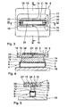
- the laser welding head 1 can be constructed as a scanner system or as a movable contour welding head.
- the in Fig. 2 dashed laser beam 3 via a defined beam path 10 (see Fig. 3 and 6 ) for machining the held in the closer to be explained clamping device 5 workpiece 4.
- the workpiece 4 consists of two components, namely a cuboidal, open-topped lower part 6 and a seated thereon, flush with the outer walls of the lower part 6 final lid 7.
- the latter consists of a transmissive to the wavelength of the laser beam 3, thermoplastic material, whereas the lower part 6 is made of a laser beam absorbing and heat converting material.
- the laser beam 3 can pass through the lid 7 and provide in the joining zone formed by the lid lower edge 8 and the upward-facing end edge 9 of the lower part 6 for a fusion of the two components 6, 7 in the above-mentioned transmission welding process.
- both components 6, 7, the lower part 6 is held in a workpiece holder 18.
- an inner clamping with an inner clamping jaw 11 is provided, which is within the in Fig. 3 and 6 dotted indicated beam path 10 is arranged.
- the inner clamping jaw 11 is above each center in the longitudinal and transverse sides 13, 14 at the top End-sitting connecting struts 15 with the in the Fig. 3 to 5 merely indicated in the form of a clamping ring chuck 16 connected.
- These connecting struts 15 bridge the beam path 10 of the laser welding head 1 to the components 6, 7 releasing passage gap 17 in the clamping head.
- Fig. 3 lamellar, with its flat main plane substantially parallel to the direction of the laser beam 3, that is aligned vertically. Furthermore, this main plane is perpendicular to the beam path 10, so that the laser beam 3 is only minimally shadowed.
- an oblique arrangement of the connecting struts may also be indicated.
- the shape of the clamping surface 12 of the inner clamping jaw 11 is - as from the 4 and 5 emerges adapted to the shape of the lid 7 and thus the weld to be applied in the joining zone between lid lower edge 8 and front edge 9 of the lower part 6.
- the introduced via the clamping head 16 clamping pressure can be cleanly distributed over the lid 7 are transferred to the lower part 6 that is countered by the workpiece holder 18.
- the surfaces of the inner clamping jaw 11 facing the passage gap 17 are inclined against the narrow transverse sides 14 and the corresponding surface 20 of the clamping head 16 counter to the beam direction, so that the passage gap 17 widens conically against the beam direction of the laser beam 3.
- the laser beam 3 can pass unhindered to the joining zone even at a shallower angle, as it prevails when creating the weld in the narrow sides.
- the two metal sheets 23, 23 'are each anchored in the annular clamping head 16.
- the metal sheets 23, 23 'further recesses 25 at its lower edge, so that when oblique to the plane of the metal sheets 23, 23' extending laser beams 3, the degree of shading is in turn minimized.
- Fig. 6 to 8 Unlike the Fig. 3 to 5 is in the embodiment according to Fig. 6 to 8 additionally provided in combination with the internal tension an external tension, which is realized by a tensioning eyeglass 27 attached to the bottom of the clamping head 16. This attacks from the outside to the workpiece 4 and acted upon with an inside in the clamping opening circulating Fixiersteg 28 the edge of the lid 7 from above. Together with the explained internal stress, the joining zone between the lid lower edge 8 and the front edge 9 of the lower part 6 is tensioned on both sides of the beam path 10.
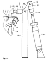
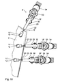
- FIG. 9 and 10 an inner clamping device is shown, in which for the tension of a lid 7 on a lower part 6, a plurality of inner clamping jaws 11 'are used. These are in turn connected via narrow, web-like connecting struts 15 'with the outer clamping heads 16' of the clamping device. With these connecting struts 15 ', in plan view ( Fig. 10 ) are formed by lateral recesses 22 of the clamping lever 29, the beam path 10 of the laser beam 3 is suppressed. Furthermore, an adaptation of the connecting webs 15 'to the Strahlkaustik through their upper and lower recesses 25th
- the tensioning levers 29 themselves are pivotably mounted on supports 30, which are arranged outside the workpiece receptacle (not shown in more detail), in a rotation axis 31.
- the piston rod 33 of a piston-cylinder drive 34 is articulated respectively.
- the piston rod 33 By retracting the piston rod 33, the inner clamping jaws 11 'can be pivoted upward and thus the workpiece 4 are removed from the laser welding device.
- the clamping pressure can also be achieved by subjecting the workpiece holder from below and thus counteracting the component to be clamped against the one- or multi-part internal clamping jaws 11, 11 '.
- the piston-cylinder drives 34 of the embodiment according to FIGS Fig. 9 and 10 are examples of the piston-cylinder drives 34 of the embodiment according to FIGS Fig. 9 and 10 .
Abstract
Description
Die Erfindung betrifft eine Spannvorrichtung zum Spannen mindestens zweier Bauteile in einer strahlgestützten Bearbeitungsmaschine, insbesondere in einer Laserschweißeinrichtung.The invention relates to a clamping device for clamping at least two components in a beam-assisted processing machine, in particular in a laser welding device.
Derartige Spannvorrichtungen sind aus einer Vielzahl von Druckschriften bekannt. So zeigt die
Bei der Schweißeinrichtung gemäß
Die
Zum Hintergrund der Erfindung ist kurz auf deren vornehmliches Anwendungsgebiet einzugehen, nämlich das so genannte Durchstrahlschweißen. Dabei wird das Einbringen der erforderlichen Laserleistung in die Fügezone dadurch erzielt, dass der Laserstrahl durch eine für den Laserwellen-Längenbereich völlig beziehungsweise zumindest teilweise transparente Decklage des einen Bauteils durchstrahlt wird. Die Laserenergie wird vom unteren Fügepartner zumindest teilweise absorbiert. Die dabei entstehende Wärme lässt den unteren Fügepartner aufschmelzen, durch Wärmeleitung aus dem zweiten Bauteil in die Decklage wird also auch das erste Bauteil aufgeschmolzen. Eine Verbindung der beiden Fügepartner findet durch Druckeinwirkung auf die Fügezone statt. Der Laserstrahl bewegt sich dabei relativ entlang der Schweißnaht.The background of the invention is briefly to address their primary field of application, namely the so-called transmission welding. In this case, the introduction of the required laser power into the joining zone is achieved by the laser beam being irradiated through a cover layer of the one component which is completely or at least partially transparent for the laser wave length region. The laser energy is at least partially absorbed by the lower joining partner. The resulting heat causes the lower joining partner to melt, so heat conduction from the second component into the cover layer also causes the first component to be melted. A connection of the two joining partners takes place by pressure on the joining zone. The laser beam moves thereby relatively along the weld.
Zum Erzeugen der Druckeinwirkung zeigt die den nächstkommenden Stand der Technik repräsentierende
Ferner ist die Außenspannvorrichtung dann problematisch anzuwenden, wenn außerhalb der Schweißnaht an den Bauteilen kein oder nicht ausreichend Material zum Ansetzen der Außenspannvorrichtung vorhanden ist.Furthermore, the outer tensioning device is problematic to apply if there is no or insufficient material for attaching the outer clamping device outside of the weld on the components.
Der Erfindung liegt nun ausgehend von der geschilderten Problematik zum Stand der Technik die Aufgabe zugrunde, eine Spannvorrichtung der gattungsgemäßen Art so auszubilden, dass zwei zu fügende Bauteile unabhängig von ihren Dimensionen universell zu spannen sind, sodass auf die problematische Außenspanntechnik gegebenenfalls ganz verzichtet werden kann.The invention is now based on the above-mentioned problem to the prior art, the object of providing a clamping device of the generic type so that two components to be joined regardless of their dimensions are universally clamped, so that may be dispensed with the problematic external clamping technology, if necessary.
Diese Aufgabe wird durch die Vorrichtung gemäβ Patentanspruches 1 gelöstThis object is achieved by the device according to
Die Erfindung schlägt also eine Innenspanntechnik vor, die bei strahlgestützten Bearbeitungsmaschinen bisher wegen der durch die innen liegenden Spannteile verbundene Abschattung nicht eingesetzt wurde. Die Erfindung geht in diesem Zusammenhang von der Erkenntnis aus, dass geringe Unterbrechungen des Bearbeitungsstrahles, wie sie durch die schmalen Verbindungsstreben zur Anbindung des Innen-Spannbackens an den außenliegenden Spannkopf nur auftreten, mit keiner nennenswerten Beeinträchtigung der Schweißnaht verbunden sind. Aufgrund der auch in Längsrichtung der Schweißnaht stattfindenden Wärmeleitung sowie einer teilweise stattfindenden Bestrahlung werden auch die von den Verbindungsstreben abgeschatteten Bereiche ausreichend mit Energie versorgt, sodass ein einwandfreies Aufschmelzen und Verschweißen der beiden Fügepartner erreicht wird.Thus, the invention proposes an internal clamping technique, which was previously not used in beam-assisted processing machines because of the shading connected by the internal clamping parts. The invention is based in this context on the recognition that small interruptions of the machining beam, as they only occur through the narrow connecting struts for connecting the inner clamping jaw to the outer chuck, are not associated with any appreciable impairment of the weld seam. Due to the heat conduction taking place also in the longitudinal direction of the weld seam and a partially occurring irradiation, the areas shaded by the connecting struts are sufficiently supplied with energy, so that a perfect melting and welding of the two joining partners is achieved.
Durch die erfindungsgemäße Innenspannung insbesondere in Kombination mit der bevorzugtermaßen vorgesehenen Außenspannung ergibt sich für die gesamte Schweißnaht eine deutlich homogenere Spanndruckverteilung, was zu geringeren Spannungen in und neben der Schweißnaht führt. Dadurch wird die Schweißnahthomogenität verbessert, wodurch gegebenenfalls mit einer geringeren Laserleistung gewünschte Schweißergebnisse erzielbar sind. Damit können dann auch Taktzeitverkürzungen bei der Bearbeitung von Werkstücken einher gehen.As a result of the internal tension according to the invention, in particular in combination with the outside tension provided by preference, a significantly more homogeneous tensioning pressure distribution results for the entire weld seam, which leads to lower stresses in and beside the weld seam. As a result, the weld homogeneity is improved, as a result of which, if desired, desired welding results can be achieved with a lower laser power. This can then be accompanied by cycle time reductions in the machining of workpieces.
Gemäß einer vorteilhaften Weiterbildung ist vorgesehen, zur Spannung dreidimensionaler Bauteile die Innenspannung durch eine Vielzahl von einzelnen Innenspannbacken vorzunehmen, die jeweils an außenliegenden, einzelnen Spannköpfen über die den Strahlweg überbrückenden Verbindungsstreben angebracht sind. Vorzugsweise sind die Innenspannbacken mit den Verbindungsstreben Teil jeweils eines Spannhebels, der mittels eines Spannantriebes, beispielsweise in Form eines Kolben-Zylinder-Antriebes, beaufschlagbar ist.According to an advantageous development is provided for tensioning three-dimensional components, the inner tension by a plurality of individual inner clamping jaws, which are each mounted on outer, individual clamping heads on the beam path bridging connecting struts. Preferably, the inner jaws with the connecting struts part each of a clamping lever, by means of a tensioning drive, for example in the form of a piston-cylinder drive, can be acted upon.
Bevorzugte Ausführungsformen, weitere Merkmale, Einzelheiten und Vorteile der Erfindung ergeben sich aus den abhängigen Ansprüchen und der nachfolgenden Beschreibung von Ausführungsbeispielen anhand der beigefugten Zeichnungen. Es zeigen:
- Fig. 1
- eine perspektivische Darstellung einer Laserschweißeinrich- tung mit einer Spannvorrichtung,
- Fig. 2
- eine Seitenansicht der Anordnung gemäß
Fig. 1 , - Fig. 3
- eine Draufsicht einer Spannvorrichtung mit Innenspannung eines Werkstücks,
- Fig. 4 und 5
- Schnittdarstellungen der Spannvorrichtung gemäß Schnittli- nie IV-IV beziehungsweise V-V nach
Fig. 3 , - Fig. 6
- eine Draufsicht einer Spannvorrichtung mit kombinierter In- nen- und Außenspannung,
- Fig. 7 und 8
- Schnittdarstellungen der Spannvorrichtung gemäß Schnittli- nie VII-VII beziehungsweise VIII-VIII nach
Fig. 6 , sowie - Fig. 9 und 10
- eine Seitenansicht und Draufsicht einer weiteren Ausfüh- rungsform einer aus einzelnen Spannbacken zusammenge- setzten Innenspannvorrichtung.
- Fig. 1
- a perspective view of a laser welding device with a clamping device,
- Fig. 2
- a side view of the arrangement according to
Fig. 1 . - Fig. 3
- a top view of a clamping device with internal stress of a workpiece,
- 4 and 5
- Sectional views of the clamping device according to section line IV-IV or VV after
Fig. 3 . - Fig. 6
- a top view of a clamping device with combined internal and external voltage,
- FIGS. 7 and 8
- Sectional views of the clamping device according to section line VII-VII or VIII-VIII according to
Fig. 6 , such as - FIGS. 9 and 10
- a side view and top view of another embodiment of a form of individual clamping jaws put together set internal jig.
Wie aus den
Über eine Bearbeitungsoptik 2 wird der in
Anhand von
Zur Spannung beider Bauteile 6, 7 ist das Unterteil 6 in einer WerkstückAufnahme 18 gehalten. Für den Deckel 7 ist eine Innenspannung mit einem Innen-Spannbacken 11 vorgesehen, der innerhalb des in
Sie sind, wie insbesondere aus
Die Form der Spannfläche 12 des Innen-Spannbackens 11 ist - wie aus den
Wie ferner aus den
Aus der Draufsicht gemäß
Wie aus den beiden Schnittdarstellungen gemäß den
Bei der in den
Im Unterschied zu den
In den
Die Spannhebel 29 selbst sind an außerhalb der nicht näher gezeigten Werkstückaufnahme angeordneten Stützen 30 in einer Drehachse 31 schwenkbar gelagert. An seinem den Innenspannbacken 11' abgewandten, nach oben abgekröpften Hebelarm 32 ist jeweils die Kolbenstange 33 eines Kolben-Zylinder-Antriebes 34 angelenkt. Mit Hilfe dieses Kolben-Zylinder-Antriebes 34 kann jeder einzelne Innen-Spannbacken 11' so beaufschlagt werden, dass er das zu spannende Bauteil, nämlich den Deckel 7 von oben innerhalb der zu erzeugenden Schweißnaht entlang des Strahlweges 10 der Laserschweißeinrichtung gegen das Unterteil 6 beaufschlagt. Durch Zurückziehen der Kolbenstange 33 können die Innenspannbacken 11' nach oben weggeschwenkt und somit das Werkstück 4 aus der Laserschweißeinrichtung entnommen werden.The tensioning levers 29 themselves are pivotably mounted on
Wenngleich aufgrund der stegartigen Verbindungsstreben 15' die Abschattung des Laserbearbeitungsstrahles so gering ist, dass eine Beeinträchtigung der herzustellenden Schweißnaht nicht zu befürchten steht, kann für besonders hohe Qualitätsanforderungen selektiv jeweils derjenige Spannbacken 11' mit Hilfe des Kolben-Zylinder-Antriebes 34 nach oben weggeschwenkt werden, der gerade im Strahlweg liegt.Although due to the web-like connecting struts 15 ', the shadowing of the laser beam is so low that a deterioration of the welded seam is not to be feared, for particularly high quality requirements selectively each of those jaws 11' with the aid of the piston-
Zu allen vorstehend erörterten Ausführungsbeispielen ist im Übrigen abschließend festzuhalten, dass der Spanndruck auch durch eine Beaufschlagung der Werkstückaufnahme von unten und damit eine Gegenfahren des zu spannenden Bauteils gegen den ein- oder mehrteiligen Innenspannbacken 11, 11' bewerkstelligt werden kann. Dann entfallen beispielsweise die Kolben-Zylinder-Antriebe 34 der Ausführungsform gemäß den
Claims (10)
- Clamping apparatus for clamping at least two component parts (6, 7) in a machine tool using a work beam (3), in particular a laser welding device (1), comprising- a carrier (18) for mounting the first component (6), and- at least one clamping chuck (16) on which a respective clamping fixture is arranged for fixing the second component (7) to bring clamping pressure to the joining face (8, 9) between both of the components (6, 7), characterized in that- the respective clamping fixture is designed as an inner clamping fixture (11, 11') placed within the circulating beam path (10) of the work beam (3) of the machine tool having a clamping surface (12) for the inner clamping of the components (6, 7),- a gap (7) for the work beam (3) separates the respective inner clamping fixture (11, 11') from the outer clamping chuck (16), and- at least one narrow connecting strut (15, 15') is provided for connecting the inner clamping fixture (11, 11') to the outer clamping chuck (16, 16'), which at least one connecting strut (15, 15) bridges the gap (17) releasing the beam path (10) of the machine tool to the components (6, 7).
- Clamping apparatus according to claim 1 characterized in that the connecting struts (15, 15') are fin-shaped, whereby the flat principal plane runs essentially parallel to the direction of the machine's laser beam (3).
- Clamping apparatus according to claim 1 or 2 characterized in that the clamping area (12) of the inner clamping fixture (11, 11') runs parallel to the faying surface (8, 9).
- Clamping apparatus according to one of the aforementioned claims characterized in that the gap (17) extends conically (3) in the opposite direction of the machine's beam (3).
- Clamping apparatus according to one of the aforementioned claims characterized in that the shape of the connecting struts (15, 15') is adapted to the caustic of the laser beam (3).
- Clamping apparatus according to one of the aforementioned claims characterized in that the clamping chuck (16) have an outer clamping fixture (27) placed outside of the circulating beam path (10) of the machine with a clamping surface (28) for outer clamping of the components (6, 7).
- Clamping apparatus according to one of the aforementioned claims characterized in that inner and/or outer clamping fixtures (11, 11', 27) are made up of multiple parts.
- Clamping apparatus according to one of the aforementioned claims characterized in that the connecting struts (15) that make up the inner clamping fixture's mount (11) are built on two crossing sheet metal strips (23, 23') embedded in the inner clamping fixture (11).
- Clamping apparatus at least according to claim 1, characterized in that in particular for the clamping of three-dimensional components a plurality of individual inner clamping fixtures (11') are each arranged on outer, individual clamping chucks (16') by the connecting struts (15').
- Clamping device according to claim 9, characterized in that the clamping chucks (16') each comprise clamping levers (29) holding the connecting struts (15'), which, by means of a clamping drive, are preferably chargeable by means of a piston cylinder drive (34).
Priority Applications (1)
| Application Number | Priority Date | Filing Date | Title |
|---|---|---|---|
| PL08735120T PL2136959T3 (en) | 2007-04-17 | 2008-04-10 | Clamping device for clamping at least two components |
Applications Claiming Priority (3)
| Application Number | Priority Date | Filing Date | Title |
|---|---|---|---|
| DE102007018385 | 2007-04-17 | ||
| DE102007042739A DE102007042739A1 (en) | 2007-04-17 | 2007-09-07 | Clamping device for clamping at least two components |
| PCT/EP2008/002808 WO2008125263A1 (en) | 2007-04-17 | 2008-04-10 | Clamping device for clamping at least two components |
Publications (2)
| Publication Number | Publication Date |
|---|---|
| EP2136959A1 EP2136959A1 (en) | 2009-12-30 |
| EP2136959B1 true EP2136959B1 (en) | 2011-05-25 |
Family
ID=39768056
Family Applications (1)
| Application Number | Title | Priority Date | Filing Date |
|---|---|---|---|
| EP08735120A Active EP2136959B1 (en) | 2007-04-17 | 2008-04-10 | Clamping device for clamping at least two components |
Country Status (11)
| Country | Link |
|---|---|
| US (1) | US8415583B2 (en) |
| EP (1) | EP2136959B1 (en) |
| JP (1) | JP5577239B2 (en) |
| KR (1) | KR101461251B1 (en) |
| CN (1) | CN101657291B (en) |
| AT (1) | ATE510649T1 (en) |
| DE (1) | DE102007042739A1 (en) |
| DK (1) | DK2136959T3 (en) |
| ES (1) | ES2365346T3 (en) |
| PL (1) | PL2136959T3 (en) |
| WO (1) | WO2008125263A1 (en) |
Cited By (2)
| Publication number | Priority date | Publication date | Assignee | Title |
|---|---|---|---|---|
| WO2013079268A1 (en) | 2011-11-30 | 2013-06-06 | Bielomatik Leuze Gmbh + Co. Kg | Clamping device and method for laser beam welding with a connecting element movable along with the laser beam |
| WO2018015524A1 (en) | 2016-07-22 | 2018-01-25 | HELLA GmbH & Co. KGaA | Clamping device of a joining device, and joining device |
Families Citing this family (18)
| Publication number | Priority date | Publication date | Assignee | Title |
|---|---|---|---|---|
| DE102009049892B3 (en) | 2009-10-20 | 2011-01-05 | Emag Holding Gmbh | Device for connecting a workpiece with a joining part using laser radiation, where the workpiece and the joining part are connected along a given joining line by a welding seam, comprises a workpiece carrier movable along a guide web |
| DE102009051672A1 (en) | 2009-10-30 | 2011-05-05 | Jenoptik Automatisierungstechnik Gmbh | Device for the transmission welding of components via an annular contact zone |
| FR2959693B1 (en) | 2010-05-07 | 2012-07-27 | Renault Sa | DEVICE FOR ASSEMBLING TWO PIECES OF THERMOPLASTIC MATERIALS BY TRANSPARENT LASER WELDING AND ASSOCIATED ASSEMBLY METHOD |
| FR2959692B1 (en) * | 2010-05-07 | 2013-12-27 | Renault Sa | DEVICE FOR ASSEMBLING TWO PIECES OF THERMOPLASTIC MATERIALS BY TRANSPARENT LASER WELDING AND ASSOCIATED ASSEMBLY METHOD |
| DE102011077962B4 (en) | 2010-09-27 | 2016-01-07 | Xenon Automatisierungstechnik Gmbh | Device for 3-D processing of components |
| WO2012085121A1 (en) | 2010-12-21 | 2012-06-28 | Bielomatik Leuze Gmbh + Co. Kg | Laser welding of plastic components using two superposed motions |
| DE102012203694A1 (en) | 2012-03-08 | 2013-09-12 | Lpkf Laser & Electronics Ag | Beam-supported joining machine, in particular laser penetrating welding device |
| DE102012216664B4 (en) | 2012-09-18 | 2016-12-15 | Lpkf Laser & Electronics Ag | Process for producing a hollow body consisting of two components, and hollow body produced therewith |
| CN102941674B (en) * | 2012-11-16 | 2015-04-22 | 江苏大学 | Laser transmission welding follow-up clamping device |
| DE102013101224A1 (en) | 2013-02-07 | 2014-08-07 | Jenoptik Automatisierungstechnik Gmbh | Laser transmission welding apparatus, laser transmission welding method, and a film sealed container therewith |
| DE102013105881A1 (en) | 2013-06-06 | 2014-12-11 | Jenoptik Automatisierungstechnik Gmbh | Devices for connecting two workpiece parts by means of laser transmission welding |
| USD774118S1 (en) * | 2013-08-29 | 2016-12-13 | Johannes Demmeler | Welding table |
| DE102013217647A1 (en) | 2013-09-04 | 2015-03-05 | Lpkf Laser & Electronics Ag | Beam-supported joining machine, in particular laser penetrating welding device |
| SI3205481T1 (en) * | 2016-02-12 | 2020-04-30 | Odelo Gmbh | Method and device for connecting lens and lamp housing of a vehicle light using laser welding |
| CN106239898A (en) * | 2016-07-27 | 2016-12-21 | 长春德信光电技术有限公司 | A kind of capsule endoscope shell laser welding packaging device and method |
| DE102018102494A1 (en) | 2018-02-05 | 2019-08-08 | Evosys Laser GmbH | Clamping device and associated laser welding device |
| CN113714642B (en) * | 2021-09-30 | 2023-05-30 | 智新科技股份有限公司 | Gear welding method and welded gear assembly |
| CN114619145B (en) * | 2022-03-10 | 2023-10-03 | 湖北三江航天红峰控制有限公司 | Laser welding device and welding method for thin-wall part |
Family Cites Families (18)
| Publication number | Priority date | Publication date | Assignee | Title |
|---|---|---|---|---|
| US4461946A (en) * | 1982-03-11 | 1984-07-24 | Hull Corporation | Apparatus for clamping an assembly of parts for laser welding |
| US5049720A (en) | 1990-08-24 | 1991-09-17 | Fmc Corporation | Laser welding apparatus with sky window |
| FR2686423B1 (en) | 1992-01-22 | 1996-12-13 | Balteau France | POLARIMETRIC BOX FOR MEASURING THE ANGLE OF FARADAY. |
| DE9319146U1 (en) * | 1993-12-14 | 1995-03-16 | Kuka Schweissanlagen & Roboter | Device for welding and / or cutting |
| EP0751865B2 (en) * | 1994-03-31 | 2004-07-14 | Marquardt GmbH | Plastic workpiece and process for producing it |
| ATE192692T1 (en) * | 1999-01-28 | 2000-05-15 | Leister Process Tech | LASER JOINING METHOD AND DEVICE FOR CONNECTING VARIOUS PLASTIC WORKPIECES OR PLASTIC WITH OTHER MATERIALS |
| DE19924469A1 (en) | 1999-05-28 | 2000-11-30 | Bielomatik Leuze & Co | Holder for plastic workpieces during laser welding, has clamping faces with individually adjustable adjacent surfaces around the welding area which move transverse to the welding plane |
| JP3584828B2 (en) * | 1999-12-28 | 2004-11-04 | 三菱電機株式会社 | Laser apparatus, optical fiber adjustment jig, and optical fiber adjustment method |
| JP2001345536A (en) * | 2000-06-02 | 2001-12-14 | Matsushita Electric Works Ltd | Method of manufacturing circuit board |
| JP2003225946A (en) | 2002-02-01 | 2003-08-12 | Denso Corp | Laser bonding method and laser bonding device |
| JP3823065B2 (en) * | 2002-04-23 | 2006-09-20 | 愛三工業株式会社 | Laser welding method |
| JP2003340584A (en) | 2002-05-22 | 2003-12-02 | Sumitomo Metal Ind Ltd | Method and apparatus for manufacturing laminated steel sheet |
| EP1518664A1 (en) * | 2003-09-20 | 2005-03-30 | Leister Process Technologies | Process and apparatus for joining components by laser radiation |
| JP4311158B2 (en) * | 2003-10-14 | 2009-08-12 | 株式会社デンソー | Resin molded product and manufacturing method thereof |
| JP2006007237A (en) * | 2004-06-23 | 2006-01-12 | Nissan Motor Co Ltd | Work clamping device for laser beam welding |
| JP2006168252A (en) * | 2004-12-17 | 2006-06-29 | Koito Mfg Co Ltd | Light welding apparatus and light welding method |
| JP4678829B2 (en) * | 2005-01-26 | 2011-04-27 | 株式会社小糸製作所 | Manufacturing method of vehicular lamp |
| JP4702183B2 (en) * | 2006-05-29 | 2011-06-15 | 株式会社デンソー | Laser welding method |
-
2007
- 2007-09-07 DE DE102007042739A patent/DE102007042739A1/en not_active Withdrawn
-
2008
- 2008-04-10 JP JP2010503383A patent/JP5577239B2/en active Active
- 2008-04-10 AT AT08735120T patent/ATE510649T1/en active
- 2008-04-10 ES ES08735120T patent/ES2365346T3/en active Active
- 2008-04-10 WO PCT/EP2008/002808 patent/WO2008125263A1/en active Application Filing
- 2008-04-10 US US12/593,058 patent/US8415583B2/en active Active
- 2008-04-10 DK DK08735120.1T patent/DK2136959T3/en active
- 2008-04-10 EP EP08735120A patent/EP2136959B1/en active Active
- 2008-04-10 KR KR1020097022254A patent/KR101461251B1/en active IP Right Grant
- 2008-04-10 CN CN2008800121386A patent/CN101657291B/en active Active
- 2008-04-10 PL PL08735120T patent/PL2136959T3/en unknown
Cited By (4)
| Publication number | Priority date | Publication date | Assignee | Title |
|---|---|---|---|---|
| WO2013079268A1 (en) | 2011-11-30 | 2013-06-06 | Bielomatik Leuze Gmbh + Co. Kg | Clamping device and method for laser beam welding with a connecting element movable along with the laser beam |
| DE102011087405A1 (en) | 2011-11-30 | 2013-06-06 | Bielomatik Leuze Gmbh + Co. Kg | Clamping device for laser beam welding |
| WO2018015524A1 (en) | 2016-07-22 | 2018-01-25 | HELLA GmbH & Co. KGaA | Clamping device of a joining device, and joining device |
| DE102016113553A1 (en) | 2016-07-22 | 2018-01-25 | HELLA GmbH & Co. KGaA | Clamping device of a joining device and joining device |
Also Published As
| Publication number | Publication date |
|---|---|
| JP5577239B2 (en) | 2014-08-20 |
| DE102007042739A1 (en) | 2008-10-23 |
| EP2136959A1 (en) | 2009-12-30 |
| PL2136959T3 (en) | 2011-10-31 |
| ES2365346T3 (en) | 2011-09-30 |
| US8415583B2 (en) | 2013-04-09 |
| ATE510649T1 (en) | 2011-06-15 |
| CN101657291B (en) | 2012-09-05 |
| KR101461251B1 (en) | 2014-11-12 |
| KR20100015874A (en) | 2010-02-12 |
| US20100140232A1 (en) | 2010-06-10 |
| DK2136959T3 (en) | 2011-09-12 |
| WO2008125263A1 (en) | 2008-10-23 |
| CN101657291A (en) | 2010-02-24 |
| JP2010524691A (en) | 2010-07-22 |
Similar Documents
| Publication | Publication Date | Title |
|---|---|---|
| EP2136959B1 (en) | Clamping device for clamping at least two components | |
| DE60209159T2 (en) | Method and apparatus for laser welding two or more overlapping sheets and clamping the sheets | |
| DE102007028706A1 (en) | Vehicle light has housing, which has front opening, and translucent covering closes front opening of housing, which is connected with housing by laser welding, where translucent covering has curved, front surface and rear surface | |
| DE10261642A1 (en) | Method and device for welding thermoplastic molded parts, in particular for contour welding three-dimensional molded parts | |
| EP3191254B1 (en) | Laser ablation and welding method for workpieces | |
| DE112011102493B4 (en) | Device for vibro spot welding | |
| EP2561949A1 (en) | Device for centring, supporting and weld bath securing when connecting, through friction stir welding, butt joints of rotation symmetric hollow bodies | |
| DE102005037134B4 (en) | Friction welding-based method for joining two flat joining partners | |
| DE102007020166A1 (en) | Tool holder with mechanical means of action | |
| DE102016110885A1 (en) | Method of welding workpieces together while minimizing warping | |
| WO2009147197A1 (en) | Clamping device and clamping method | |
| DE102012213651B3 (en) | Holding device and method for operating a holding device | |
| CH689714A5 (en) | Apparatus for joining two workpieces. | |
| DE3219252C2 (en) | ||
| DE102008044087A1 (en) | Method of making lap joint welds and overlap butt weld joint | |
| DE4131465C2 (en) | Device for ultrasonic welding of sealed seams | |
| EP3749507B1 (en) | Clamping device and associated laser welding apparatus | |
| WO2015032719A1 (en) | Beam-assisted joining machine, in particular laser transmission welding device having a clamping means formed by a flexible clamping hose | |
| EP2764981B1 (en) | Device for laser transmission welding, method for laser transmission welding and container sealed with film produced with the same | |
| DE102019114875A1 (en) | METHOD AND DEVICE FOR LASER WELDING | |
| DE102021131399A1 (en) | METHOD AND DEVICE FOR APPLYING AN ACTIVE JOINING FORCE DURING LASER WELDING OF OVERLAPPING WORKPIECES | |
| EP3541560A1 (en) | Laser pressure welding | |
| AT525466A1 (en) | DEVICE AND METHOD FOR LASER WELDING OF STEEL PLATES | |
| DE102014212837B4 (en) | Joining device and method for joining workpieces subject to tolerances | |
| EP1849560B1 (en) | Compacting tool with layered die stock element |
Legal Events
| Date | Code | Title | Description |
|---|---|---|---|
| PUAI | Public reference made under article 153(3) epc to a published international application that has entered the european phase |
Free format text: ORIGINAL CODE: 0009012 |
|
| 17P | Request for examination filed |
Effective date: 20090904 |
|
| AK | Designated contracting states |
Kind code of ref document: A1 Designated state(s): AT BE BG CH CY CZ DE DK EE ES FI FR GB GR HR HU IE IS IT LI LT LU LV MC MT NL NO PL PT RO SE SI SK TR |
|
| DAX | Request for extension of the european patent (deleted) | ||
| GRAP | Despatch of communication of intention to grant a patent |
Free format text: ORIGINAL CODE: EPIDOSNIGR1 |
|
| GRAS | Grant fee paid |
Free format text: ORIGINAL CODE: EPIDOSNIGR3 |
|
| GRAA | (expected) grant |
Free format text: ORIGINAL CODE: 0009210 |
|
| AK | Designated contracting states |
Kind code of ref document: B1 Designated state(s): AT BE BG CH CY CZ DE DK EE ES FI FR GB GR HR HU IE IS IT LI LT LU LV MC MT NL NO PL PT RO SE SI SK TR |
|
| REG | Reference to a national code |
Ref country code: GB Ref legal event code: FG4D Free format text: NOT ENGLISH |
|
| REG | Reference to a national code |
Ref country code: CH Ref legal event code: EP |
|
| REG | Reference to a national code |
Ref country code: IE Ref legal event code: FG4D Free format text: LANGUAGE OF EP DOCUMENT: GERMAN |
|
| REG | Reference to a national code |
Ref country code: DE Ref legal event code: R096 Ref document number: 502008003680 Country of ref document: DE Effective date: 20110707 |
|
| REG | Reference to a national code |
Ref country code: NL Ref legal event code: T3 |
|
| REG | Reference to a national code |
Ref country code: DK Ref legal event code: T3 |
|
| REG | Reference to a national code |
Ref country code: ES Ref legal event code: FG2A Ref document number: 2365346 Country of ref document: ES Kind code of ref document: T3 Effective date: 20110930 |
|
| PG25 | Lapsed in a contracting state [announced via postgrant information from national office to epo] |
Ref country code: HR Free format text: LAPSE BECAUSE OF FAILURE TO SUBMIT A TRANSLATION OF THE DESCRIPTION OR TO PAY THE FEE WITHIN THE PRESCRIBED TIME-LIMIT Effective date: 20110525 Ref country code: PT Free format text: LAPSE BECAUSE OF FAILURE TO SUBMIT A TRANSLATION OF THE DESCRIPTION OR TO PAY THE FEE WITHIN THE PRESCRIBED TIME-LIMIT Effective date: 20110926 Ref country code: SE Free format text: LAPSE BECAUSE OF FAILURE TO SUBMIT A TRANSLATION OF THE DESCRIPTION OR TO PAY THE FEE WITHIN THE PRESCRIBED TIME-LIMIT Effective date: 20110525 Ref country code: NO Free format text: LAPSE BECAUSE OF FAILURE TO SUBMIT A TRANSLATION OF THE DESCRIPTION OR TO PAY THE FEE WITHIN THE PRESCRIBED TIME-LIMIT Effective date: 20110825 Ref country code: LT Free format text: LAPSE BECAUSE OF FAILURE TO SUBMIT A TRANSLATION OF THE DESCRIPTION OR TO PAY THE FEE WITHIN THE PRESCRIBED TIME-LIMIT Effective date: 20110525 |
|
| REG | Reference to a national code |
Ref country code: PL Ref legal event code: T3 |
|
| PG25 | Lapsed in a contracting state [announced via postgrant information from national office to epo] |
Ref country code: IS Free format text: LAPSE BECAUSE OF FAILURE TO SUBMIT A TRANSLATION OF THE DESCRIPTION OR TO PAY THE FEE WITHIN THE PRESCRIBED TIME-LIMIT Effective date: 20110925 Ref country code: CY Free format text: LAPSE BECAUSE OF FAILURE TO SUBMIT A TRANSLATION OF THE DESCRIPTION OR TO PAY THE FEE WITHIN THE PRESCRIBED TIME-LIMIT Effective date: 20110525 Ref country code: FI Free format text: LAPSE BECAUSE OF FAILURE TO SUBMIT A TRANSLATION OF THE DESCRIPTION OR TO PAY THE FEE WITHIN THE PRESCRIBED TIME-LIMIT Effective date: 20110525 Ref country code: SI Free format text: LAPSE BECAUSE OF FAILURE TO SUBMIT A TRANSLATION OF THE DESCRIPTION OR TO PAY THE FEE WITHIN THE PRESCRIBED TIME-LIMIT Effective date: 20110525 Ref country code: GR Free format text: LAPSE BECAUSE OF FAILURE TO SUBMIT A TRANSLATION OF THE DESCRIPTION OR TO PAY THE FEE WITHIN THE PRESCRIBED TIME-LIMIT Effective date: 20110826 Ref country code: LV Free format text: LAPSE BECAUSE OF FAILURE TO SUBMIT A TRANSLATION OF THE DESCRIPTION OR TO PAY THE FEE WITHIN THE PRESCRIBED TIME-LIMIT Effective date: 20110525 |
|
| REG | Reference to a national code |
Ref country code: IE Ref legal event code: FD4D |
|
| REG | Reference to a national code |
Ref country code: HU Ref legal event code: AG4A Ref document number: E012082 Country of ref document: HU |
|
| PG25 | Lapsed in a contracting state [announced via postgrant information from national office to epo] |
Ref country code: EE Free format text: LAPSE BECAUSE OF FAILURE TO SUBMIT A TRANSLATION OF THE DESCRIPTION OR TO PAY THE FEE WITHIN THE PRESCRIBED TIME-LIMIT Effective date: 20110525 Ref country code: IE Free format text: LAPSE BECAUSE OF FAILURE TO SUBMIT A TRANSLATION OF THE DESCRIPTION OR TO PAY THE FEE WITHIN THE PRESCRIBED TIME-LIMIT Effective date: 20110525 Ref country code: CZ Free format text: LAPSE BECAUSE OF FAILURE TO SUBMIT A TRANSLATION OF THE DESCRIPTION OR TO PAY THE FEE WITHIN THE PRESCRIBED TIME-LIMIT Effective date: 20110525 |
|
| PG25 | Lapsed in a contracting state [announced via postgrant information from national office to epo] |
Ref country code: RO Free format text: LAPSE BECAUSE OF FAILURE TO SUBMIT A TRANSLATION OF THE DESCRIPTION OR TO PAY THE FEE WITHIN THE PRESCRIBED TIME-LIMIT Effective date: 20110525 Ref country code: SK Free format text: LAPSE BECAUSE OF FAILURE TO SUBMIT A TRANSLATION OF THE DESCRIPTION OR TO PAY THE FEE WITHIN THE PRESCRIBED TIME-LIMIT Effective date: 20110525 |
|
| PLBI | Opposition filed |
Free format text: ORIGINAL CODE: 0009260 |
|
| PLAX | Notice of opposition and request to file observation + time limit sent |
Free format text: ORIGINAL CODE: EPIDOSNOBS2 |
|
| 26 | Opposition filed |
Opponent name: BIELOMATIK LEUZE GMBH + CO. KG Effective date: 20120227 |
|
| REG | Reference to a national code |
Ref country code: DE Ref legal event code: R026 Ref document number: 502008003680 Country of ref document: DE Effective date: 20120227 |
|
| PLAF | Information modified related to communication of a notice of opposition and request to file observations + time limit |
Free format text: ORIGINAL CODE: EPIDOSCOBS2 |
|
| PLBB | Reply of patent proprietor to notice(s) of opposition received |
Free format text: ORIGINAL CODE: EPIDOSNOBS3 |
|
| PG25 | Lapsed in a contracting state [announced via postgrant information from national office to epo] |
Ref country code: MC Free format text: LAPSE BECAUSE OF NON-PAYMENT OF DUE FEES Effective date: 20120430 |
|
| PG25 | Lapsed in a contracting state [announced via postgrant information from national office to epo] |
Ref country code: BG Free format text: LAPSE BECAUSE OF FAILURE TO SUBMIT A TRANSLATION OF THE DESCRIPTION OR TO PAY THE FEE WITHIN THE PRESCRIBED TIME-LIMIT Effective date: 20110825 |
|
| PG25 | Lapsed in a contracting state [announced via postgrant information from national office to epo] |
Ref country code: MT Free format text: LAPSE BECAUSE OF FAILURE TO SUBMIT A TRANSLATION OF THE DESCRIPTION OR TO PAY THE FEE WITHIN THE PRESCRIBED TIME-LIMIT Effective date: 20110525 |
|
| PG25 | Lapsed in a contracting state [announced via postgrant information from national office to epo] |
Ref country code: TR Free format text: LAPSE BECAUSE OF FAILURE TO SUBMIT A TRANSLATION OF THE DESCRIPTION OR TO PAY THE FEE WITHIN THE PRESCRIBED TIME-LIMIT Effective date: 20110525 |
|
| REG | Reference to a national code |
Ref country code: FR Ref legal event code: PLFP Year of fee payment: 8 |
|
| TPAC | Observations filed by third parties |
Free format text: ORIGINAL CODE: EPIDOSNTIPA |
|
| PLCK | Communication despatched that opposition was rejected |
Free format text: ORIGINAL CODE: EPIDOSNREJ1 |
|
| APBM | Appeal reference recorded |
Free format text: ORIGINAL CODE: EPIDOSNREFNO |
|
| APBP | Date of receipt of notice of appeal recorded |
Free format text: ORIGINAL CODE: EPIDOSNNOA2O |
|
| PLAB | Opposition data, opponent's data or that of the opponent's representative modified |
Free format text: ORIGINAL CODE: 0009299OPPO |
|
| APAH | Appeal reference modified |
Free format text: ORIGINAL CODE: EPIDOSCREFNO |
|
| REG | Reference to a national code |
Ref country code: DE Ref legal event code: R100 Ref document number: 502008003680 Country of ref document: DE |
|
| R26 | Opposition filed (corrected) |
Opponent name: BIELOMATIK LEUZE GMBH + CO. KG Effective date: 20120227 |
|
| APBU | Appeal procedure closed |
Free format text: ORIGINAL CODE: EPIDOSNNOA9O |
|
| REG | Reference to a national code |
Ref country code: FR Ref legal event code: PLFP Year of fee payment: 9 |
|
| PGFP | Annual fee paid to national office [announced via postgrant information from national office to epo] |
Ref country code: LU Payment date: 20160422 Year of fee payment: 9 |
|
| PLBN | Opposition rejected |
Free format text: ORIGINAL CODE: 0009273 |
|
| STAA | Information on the status of an ep patent application or granted ep patent |
Free format text: STATUS: OPPOSITION REJECTED |
|
| PGFP | Annual fee paid to national office [announced via postgrant information from national office to epo] |
Ref country code: NL Payment date: 20160422 Year of fee payment: 9 |
|
| 27O | Opposition rejected |
Effective date: 20160122 |
|
| PGFP | Annual fee paid to national office [announced via postgrant information from national office to epo] |
Ref country code: BE Payment date: 20160422 Year of fee payment: 9 Ref country code: AT Payment date: 20160311 Year of fee payment: 9 Ref country code: IT Payment date: 20160422 Year of fee payment: 9 Ref country code: DK Payment date: 20160425 Year of fee payment: 9 |
|
| REG | Reference to a national code |
Ref country code: FR Ref legal event code: PLFP Year of fee payment: 10 |
|
| REG | Reference to a national code |
Ref country code: DK Ref legal event code: EBP Effective date: 20170430 |
|
| REG | Reference to a national code |
Ref country code: NL Ref legal event code: MM Effective date: 20170501 |
|
| REG | Reference to a national code |
Ref country code: AT Ref legal event code: MM01 Ref document number: 510649 Country of ref document: AT Kind code of ref document: T Effective date: 20170410 |
|
| PG25 | Lapsed in a contracting state [announced via postgrant information from national office to epo] |
Ref country code: NL Free format text: LAPSE BECAUSE OF NON-PAYMENT OF DUE FEES Effective date: 20170501 Ref country code: AT Free format text: LAPSE BECAUSE OF NON-PAYMENT OF DUE FEES Effective date: 20170410 |
|
| PG25 | Lapsed in a contracting state [announced via postgrant information from national office to epo] |
Ref country code: LU Free format text: LAPSE BECAUSE OF NON-PAYMENT OF DUE FEES Effective date: 20170410 |
|
| REG | Reference to a national code |
Ref country code: BE Ref legal event code: MM Effective date: 20170430 |
|
| REG | Reference to a national code |
Ref country code: FR Ref legal event code: PLFP Year of fee payment: 11 |
|
| PG25 | Lapsed in a contracting state [announced via postgrant information from national office to epo] |
Ref country code: DK Free format text: LAPSE BECAUSE OF NON-PAYMENT OF DUE FEES Effective date: 20170430 |
|
| PG25 | Lapsed in a contracting state [announced via postgrant information from national office to epo] |
Ref country code: IT Free format text: LAPSE BECAUSE OF NON-PAYMENT OF DUE FEES Effective date: 20170410 Ref country code: BE Free format text: LAPSE BECAUSE OF NON-PAYMENT OF DUE FEES Effective date: 20170430 |
|
| PGFP | Annual fee paid to national office [announced via postgrant information from national office to epo] |
Ref country code: PL Payment date: 20230309 Year of fee payment: 16 |
|
| PGFP | Annual fee paid to national office [announced via postgrant information from national office to epo] |
Ref country code: FR Payment date: 20230417 Year of fee payment: 16 Ref country code: ES Payment date: 20230517 Year of fee payment: 16 Ref country code: DE Payment date: 20230629 Year of fee payment: 16 Ref country code: CH Payment date: 20230502 Year of fee payment: 16 |
|
| PGFP | Annual fee paid to national office [announced via postgrant information from national office to epo] |
Ref country code: HU Payment date: 20230405 Year of fee payment: 16 |
|
| PGFP | Annual fee paid to national office [announced via postgrant information from national office to epo] |
Ref country code: GB Payment date: 20230420 Year of fee payment: 16 |