EP2136572A1 - Speaker - Google Patents
Speaker Download PDFInfo
- Publication number
- EP2136572A1 EP2136572A1 EP09007888A EP09007888A EP2136572A1 EP 2136572 A1 EP2136572 A1 EP 2136572A1 EP 09007888 A EP09007888 A EP 09007888A EP 09007888 A EP09007888 A EP 09007888A EP 2136572 A1 EP2136572 A1 EP 2136572A1
- Authority
- EP
- European Patent Office
- Prior art keywords
- enclosure
- flying bridge
- flying
- wedge
- inner walls
- Prior art date
- Legal status (The legal status is an assumption and is not a legal conclusion. Google has not performed a legal analysis and makes no representation as to the accuracy of the status listed.)
- Granted
Links
Images




Classifications
-
- H—ELECTRICITY
- H04—ELECTRIC COMMUNICATION TECHNIQUE
- H04R—LOUDSPEAKERS, MICROPHONES, GRAMOPHONE PICK-UPS OR LIKE ACOUSTIC ELECTROMECHANICAL TRANSDUCERS; ELECTRIC HEARING AIDS; PUBLIC ADDRESS SYSTEMS
- H04R1/00—Details of transducers, loudspeakers or microphones
- H04R1/20—Arrangements for obtaining desired frequency or directional characteristics
- H04R1/22—Arrangements for obtaining desired frequency or directional characteristics for obtaining desired frequency characteristic only
- H04R1/28—Transducer mountings or enclosures modified by provision of mechanical or acoustic impedances, e.g. resonator, damping means
- H04R1/2869—Reduction of undesired resonances, i.e. standing waves within enclosure, or of undesired vibrations, i.e. of the enclosure itself
- H04R1/2884—Reduction of undesired resonances, i.e. standing waves within enclosure, or of undesired vibrations, i.e. of the enclosure itself by means of the enclosure structure, i.e. strengthening or shape of the enclosure
- H04R1/2888—Reduction of undesired resonances, i.e. standing waves within enclosure, or of undesired vibrations, i.e. of the enclosure itself by means of the enclosure structure, i.e. strengthening or shape of the enclosure for loudspeaker transducers
-
- H—ELECTRICITY
- H04—ELECTRIC COMMUNICATION TECHNIQUE
- H04R—LOUDSPEAKERS, MICROPHONES, GRAMOPHONE PICK-UPS OR LIKE ACOUSTIC ELECTROMECHANICAL TRANSDUCERS; ELECTRIC HEARING AIDS; PUBLIC ADDRESS SYSTEMS
- H04R1/00—Details of transducers, loudspeakers or microphones
- H04R1/20—Arrangements for obtaining desired frequency or directional characteristics
- H04R1/22—Arrangements for obtaining desired frequency or directional characteristics for obtaining desired frequency characteristic only
- H04R1/28—Transducer mountings or enclosures modified by provision of mechanical or acoustic impedances, e.g. resonator, damping means
- H04R1/2869—Reduction of undesired resonances, i.e. standing waves within enclosure, or of undesired vibrations, i.e. of the enclosure itself
- H04R1/2876—Reduction of undesired resonances, i.e. standing waves within enclosure, or of undesired vibrations, i.e. of the enclosure itself by means of damping material, e.g. as cladding
- H04R1/288—Reduction of undesired resonances, i.e. standing waves within enclosure, or of undesired vibrations, i.e. of the enclosure itself by means of damping material, e.g. as cladding for loudspeaker transducers
Definitions
- the present invention relates to a speaker having a structure to control vibration generated from an enclosure as a result of vibration generated from a speaker drive unit.
- a speaker drive unit vibrates during emission of sound, and the vibration is transmitted from the speaker drive unit to an enclosure. As a result, the enclosure vibrates. Consequently, enclosure reverberation occurs, and therefore, noise is generated, with the result that sound quality is deteriorated. For this reason, a speaker capable of reducing vibration generated from an enclosure has been proposed (for example, see Japanese Patent Application Publication No. 2000-125380 ).
- Japanese Patent Application Publication No. 2000-125380 discloses a speaker box using a composite material, such as medium density fiberboard (MDF), wherein damping sheets are applied to walls of an enclosure.
- MDF medium density fiberboard
- the device of Japanese Patent Application Publication No. 2000-125380 has a problem in that it is not possible to completely control vibration generated from the main body of the speaker box although the vibration is reduced. Also, the composite material used to constitute each wall of the enclosure is expensive. Furthermore, it is necessary to select the quality of the composite material through trial and error to obtain optimal effects, which is time-consuming.
- the speaker according to the present invention interconnects inner walls of the enclosure using a flying bridge.
- the flying bridge has a recess formed at location excluding portions abutting the inner walls.
- a damping material is fitted in the recess. Consequently, the flying bridge having the recess formed therein interconnects the inner walls of the enclosure and, in addition, serves as an elastic body.
- the damping material fitted in the recess absorbs vibration transmitted to the flying bridge.
- vibration generated from a speaker drive unit is transmitted to the enclosure, the flying bridge absorbs the vibration of the enclosure, thereby controlling the vibration of the enclosure. As a result, it is possible to control noise caused by the vibration generated from the enclosure.
- the flying bridge is constructed such that the recess is formed in the flying bridge, and the damping material is fitted in the recess, it is possible to prepare the flying bridge inexpensively and easily.
- the speaker according to the present invention may be constructed such that the flying bridge interconnects opposite ones of the inner walls of the enclosure. Consequently, it is possible for the opposite inner walls not to vibrate.
- the speaker according to the present invention may be constructed such that the flying bridge interconnects portions of the inner walls which would develop a maximum amplitude of the vibration under a free state.
- the flying bridge interconnects appropriate centers of two inner walls which are maximally movable area. Consequently, the flying bridge is connected to the positions having the maximum amplitude, and therefore, it is possible to most effectively control vibration generated from the enclosure.
- the speaker according to the present invention may be constructed such that the flying bridge comprises a plurality of wedge-shaped parts contacting each other at planes not parallel to the inner walls interconnected by the flying bridge, and the wedge-shaped parts are arranged such that a front end of one wedge-shaped part is directed opposite to a front end of another wedge-shaped part which is adjacent to the one wedge-shaped part.
- the plurality of the wedge-shaped parts comprise a pair of the wedge-shaped parts, wherein one of the wedge-shaped parts is formed with the recess and the damping material is fitted in the recess, while the other wedge-shaped part is not formed with a recess nor does have a damping material.
- the respective parts may be disposed and fixed to the inner walls of the enclosure as follows. First, the front end of the part A is directed to the front of the enclosure, and one face of the part A is directly fixed to the middle of the inner wall of the left-side face of the enclosure. Subsequently, the front end of the part B is directed to the rear of the enclosure, and one face of the part B is brought into contact with the middle of the inner wall of the right-side face of the enclosure. Subsequently, the parts A and B are disposed such that planes of the parts A and B oblique to the inner wall faces of the enclosure come into contact with each other.
- the respective parts are slid until the inner walls of the enclosure are interconnected by the respective parts. Consequently, it is possible to install the respective parts of the flying bridge in the enclosure without adjusting the size (width) of the flying bridge based on the distance between the opposite inner walls of the enclosure, thereby achieving easy preparation of the flying bridge without the necessity to precisely adjust the size of the flying bridge to suit various enclosures.
- the speaker according to the present invention may be constructed such that the flying bridge interconnects neighboring ones of the inner walls of the enclosure.
- the flying bridge it is possible for the flying bridge to interconnect the neighboring inner walls of the enclosure, for example, even when the opposite inner walls of the enclosure cannot be interconnected due to the presence of the speaker drive unit or the like, and therefore, it is possible for the enclosure not to vibrate.
- the speaker according to the present invention may be constructed such that the damping material is fitted in the recess in a contracted state. Consequently, the damping material is kept contracted by the recess, and therefore, it is possible to retain the damping material in the recess without adhesion. According to the present invention, it is possible for the speaker to reliably control vibration generated from the enclosure, thereby improving sound quality without deterioration of sound quality due to noise caused by the vibration generated from the enclosure. Also, it is possible to control noise caused by the vibration generated from the enclosure inexpensively and easily.
- FIG. 1 is a view illustrating a flying bridge according to the first embodiment of the present invention.
- FIG. 1(A) is a front view showing wood which is a material for a flying bridge
- FIG. 1(B) is a front view schematically showing the flying bridge.
- FIG. 2 is a view illustrating a process of installing the flying bridge.
- FIG. 2(A) is a see-through plan view showing the interior of an enclosure of the speaker before the installation of the flying bridge
- FIG. 2(B) is a see-through plan view showing the interior of the enclosure after the installation of the flying bridge.
- FIG. 1 is a view illustrating a flying bridge according to the first embodiment of the present invention.
- FIG. 1(A) is a front view showing wood which is a material for a flying bridge
- FIG. 1(B) is a front view schematically showing the flying bridge.
- FIG. 2 is a view illustrating a process of installing the flying bridge.
- FIG. 2(A) is a see-through
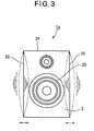
- FIG. 3 is a conceptional view illustrating vibration generated from an enclosure of a speaker.
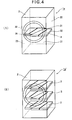
- FIG. 4 is a see-through perspective view illustrating the enclosure in which the installation of the flying bridge is completed.
- FIG. 4(A) shows the installation of a single flying bridge, and
- FIG. 4(B) shows the installation of multiple flying bridges.
- the flying bridge 3 is formed of rectangular parallelepiped wood 5 having a predetermined thickness.
- the wood 5 may be medium density fiberboard (MDF) or other inexpensive materials.
- the flying bridge 3 is composed of a pair of parts 3a and 3b obtained by cutting the rectangular parallelepiped wood 5 along a straight line L passing through an appropriate center O of the rectangular parallelepiped wood 5. At this time, the oblique line L is not parallel to the respective sides of the wood 5.
- the parts 3a and 3b of the flying bridge 3 are formed in the shape of a right angle trapezoid, the section of which is an oblique side.
- the shape of the parts 3a and 3b are not limited to the right angle trapezoid.
- the parts 3a and 3b may be formed in the shape of a wedge.
- the parts 3a and 3b may also be formed in the shape of a triangle. When the parts 3a and 3b are formed in the triangular shape, however, acute-angle portions of the parts 3a and 3b may have low strength. Consequently, it is necessary to pay attention to this point when installing the flying bridge 3.
- each of the parts 3a and 3b is provided with a recess 30, which is a cutout formed by cutting each of the parts 3a and 3b from an appropriate middle of one of the edges extending from the section 31, e.g., a long edge 33, toward an appropriate middle of the other of the edges extending from the section 31, e.g., a short edge 34. It is preferable for each recess 30 to have a uniform width.
- a damping material 4 which is located at the edge face 33 side.
- Each damping material 4 may have a free thickness greater than the width of each recess 30 and a length equivalent to about half that of each recess 30.
- each damping material 4 is a material having small temporal change and small compression distortion.
- each damping material 4 may be high-density urethane foam.
- the inexpensive wood 5 is cut, and the recesses 30, in which the respective damping materials 4 are fitted, are formed in the respective divided parts of the wood 5, as described above, it is possible to prepare the flying bridge 3 easily and inexpensively. Also, since the damping materials 4, the thickness of which is greater than the width of the recesses 30, are fitted in the respective recesses 30, it is possible to easily fix the damping materials 4 in the respective recesses 20 by pressing the damping materials 4.
- the part 3a is disposed such that a side face 32 of the part 3a comes into contact with the inner wall of a left-side face 23 of the enclosure 2.
- the part 3b is disposed such that a side face 32 of the part 3b is parallel to the inner wall of a right-side face 22 of the enclosure 2 and such that the section 31 of the part 3b comes into contact with the section 31 of the part 3a.
- the part 3b is moved along the slant section 31 of the part 3a in the direction indicated by an arrow 7.
- the flying bridge 3 When the flying bridge 3 is installed as described above, vibration generated from the opposite side faces 22 and 23 of the enclosure 2 is transmitted to the flying bridge 3 (the parts 3a and 3b), and the recesses 30, running appropriately parallel to the faces 32, expand and contract in response to the vibration. That is, the recesses 30 serve as an elastic body. Also, the damping materials 4 fitted in the respective recesses 30 absorb and convert the expansion and contraction (vibration) energy into thermal energy, which is dissipated to the outside.
- the flying bridge 3 to absorb vibration generated from the opposite inner walls of the enclosure 2. Also, since the flying bridge 3 is constituted by the wedge-shaped parts, it is possible to easily install the flying bridge 3 to the inner walls of the enclosure 2.
- the flying bridge 3 (the distance between the side face 32 of the part 3a and the side face 32 of the part 3b) only by moving the part 3b along the slant section 31 of the part 3a. Consequently, even when the distance between the opposite inner walls of the enclosure 2 varies to some extent due to an error or allowance during the manufacture of the enclosure 2, it is possible for the flying bridge 3 to reliably interconnect the opposite inner walls of the enclosure 2. For this reason, it is not necessary to precisely measure the distance between the inner walls of the speaker 1a, during the preparation of the flying bridge 3, whereby it is possible to easily produce the flying bridge 3.
- the flying bridge 3 is installed, as shown in FIG. 4(A) , such that portions having the maximum amplitude corresponding to approximate centers of the inner walls of the side faces 22 and 23 (the wall faces having the maximum area) of the speaker 1a are connected to each other. As a result, it is possible for the flying bridge 3 to more effectively absorb vibration generated from the enclosure 2.
- One or more flying bridges 3 may be installed.
- FIG. 4(B) it is preferable to install a plurality of flying bridges 3 since such a plurality of flying bridges absorb vibration generated from the enclosure 2 more effectively than only one flying bridge.
- the flying bridge 3 according to the first embodiment of the present invention is prepared such that the opposite sides (the side face 32 of the part 3a and the side face 32 of the part 3b, the faces 33 and 34 of the parts 3a and 3b) are parallel to each other.
- the side faces 33 and 34 of the parts 3a and 3b, which do not contact the enclosure 2 may not be parallel to each other.
- the parts 3a and 3b of the flying bridge 3 according to the first embodiment of the present invention is explained as being installed to push against the opposite side faces 22 and 23 of the enclosure 2, to which, however, the present invention is not limited.
- the flying bridge 3 may by installed such that the opposite side faces 22 and 23 of the enclosure 2 are pulled toward each other.
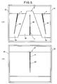
- FIG. 5 is a front view illustrating another example of the flying bridge according to the first embodiment of the present invention.
- the flying bridge 3 is explained as being constituted by the two parts, to which, however, the present invention is not limited.
- the flying bridge may include three or more of wedge-shaped parts.
- a flying bridge 3' shown in FIG. 5(A) includes a plurality of parts 3a' to 3c' formed by cutting the wood 5 along oblique straight lines not parallel to the respective sides constituting the outer circumference of the wood 5. In each part is formed a recess 30', in which a damping material 4 is fitted.
- a flying bridge 3" may comprise a single part.
- the flying bridge 3" is fixed to the opposite side faces of the enclosure 2 by screws such that the opposite side faces of the enclosure 2 are interconnected to each other by the flying bridge 3".
- FIG. 6 is a front view illustrating a further example of the flying bridge according to the first embodiment of the present invention.
- the recess 30 is explained as being formed in each part of the flying bridge, to which, however, the present invention is not limited.
- a recess 30''' may be formed in some of the parts of the flying bridge.
- a flying bridge 3''' shown in FIG. 6 includes a plurality of parts 3a''' and 3b'''' formed by cutting the wood 5 along a straight line not parallel to the respective sides constituting the outer circumference of the wood 5.
- a recess 30"' in which a damping material 4 is fitted.
- the flying bridge 3 As described above, it is possible to prepare the flying bridge 3 inexpensively and easily. Also, the flying bridge 3 absorbs vibration generated from the enclosure 2. As a result, it is possible to control vibration generated from the enclosure 2. Consequently, it is possible for the flying bridge 3 to control noise caused by vibration generated at the enclosure 2 inexpensively and easily.
- FIG. 7 is a schematic view illustrating a flying bridge according to a second embodiment of the present invention.
- FIG. 7(A) is a front view showing wood which is a material for a flying bridge
- FIG. 7(B) is a front view schematically showing the flying bridge.
- FIG. 8 is a see-through perspective view illustrating an enclosure in which the installation of the flying bridge is completed.
- the second embodiment is different from the first embodiment in the shape of a flying bridge 6 and in the connection between neighboring inner walls of an enclosure 2 using the flying bridge 6. Therefore, only the differences of the second embodiment from the first embodiment will be described hereinafter.
- the shape of flying bridges 6 installed in an enclosure 2 of a speaker 1b and a method of preparing the flying bridges 6 will be described.
- the flying bridges 6 are prepared by cutting a rectangular parallelepiped wood 5 along a straight line L passing through an appropriate center O of the rectangular parallelepiped wood 5. Consequently, the flying bridges 6 are formed in the shape of a right angle trapezoid, to which, however, the present invention is not limited.
- the flying bridge 6 is provided with a recess 60, which is formed by cutting the flying bridge 6 from an appropriate middle of a section 61 of the wood 5 toward a corner A (a corner between a side face 62 and a side face 63).
- a damping material 4 which is located at the section 61 side, in the same manner as in parts 3a and 3b of the flying bridge 3.
- the damping material 4 has a thickness greater than the width of the recess 60. Consequently, the damping material 4 is fitted in the recess 60 in a contracted state. Since the inexpensive wood 5 is cut, and the recess 60, in which the damping material 4 is fitted, is formed in each divided part of the wood 5, as described above, it is possible to prepare the flying bridges 6 easily and inexpensively.
- the flying bridges 6 are installed such that the flying bridges 6 interconnect the neighboring inner walls of the enclosure 2.
- the flying bridges 6 are fixed to the neighboring inner walls of the enclosure 2 by an adhesive such that the side faces 62 and 63 of the respective flying bridges 6 come into contact with the neighboring inner walls of the enclosure 2.
- the flying bridges 6 When the flying bridges 6 are installed as described above, vibration generated from the neighboring inner walls of the enclosure 2 is transmitted to the flying bridges 6, and the recesses 60 expand and contract in response to the vibration. That is, the recesses 60 serve as an elastic body. Also, the damping materials 4 fitted in the respective recesses 60 absorb and convert the expansion and contraction (vibration) energy into thermal energy, which is dissipated to the outside.
- a portion having the maximum amplitude corresponding to an approximate center of the inner wall of the right-side face 22 (the wall face having the maximum area) of the enclosure 2 may be connected to the inner wall of one of an installation face 21, a bottom face 24, a top face 25, or a rear face 26 neighboring to the right-side face 22.
- a portion having the maximum amplitude corresponding to an approximate center of the inner wall of the left-side face 23 of the enclosure 2 may be connected to the inner wall of one of the installation face 21, the bottom face 24, the top face 25, or the rear face 26 neighboring to the left-side face 22. Consequently, it is possible for the flying bridges 6 to absorb vibration generated from the portions having the maximum amplitude, thereby effectively absorbing vibration generated from the enclosure 2.
- the amplitude increases to such an extent that the distance between opposite pairs of sides 221 to 224 forming the right-side face 22 of the enclosure 2 (the distance between the long side 221 and the long side 223, the distance between the short side 222 and the short side 224) increases.
- the flying bridge 6 it is preferable to install the flying bridge 6 such that the corner A of the flying bridge 6 comes into contact with the middle of a short side 232 (or a short side 234) forming the left-side face 23 of the enclosure 2, not long sides 231 and 233 forming the left-side face 23. Consequently, it is possible for the flying bridge 6 to effectively absorb vibration generated from the portion having the maximum amplitude, thereby effectively absorbing vibration generated from the enclosure 2.
- the flying bridge 6 to absorb vibration generated from the neighboring inner walls (the inner wall of the side face 22 and the inner wall of the bottom face 24) of the enclosure 2. Also, it is possible to easily fix the flying bridge 6 to the inner walls of the enclosure 2.
- each flying bridge 6 is installed in the enclosure 2 such that the face 62 having an obtuse-angle front end comes into contact with the portion having the maximum amplitude, and the face 63 having an acute-angle front end comes into contact with the neighboring inner wall. That is, since the high-strength side of each flying bridge 6 is fixed to the side having large amplitude, it is possible to more securely connect the neighboring inner wall to the side having large amplitude. Furthermore, the number of the flying bridges 6 is not particularly restricted. As shown in FIG. 8(B) , it is preferable to install a plurality of flying bridges 6 since the plurality of flying bridges absorb vibration generated from the enclosure 2 more effectively than only one flying bridge.
- the installation face 21 is prepared more rigidly than other wall faces, since the speaker drive unit 20 is fixed to the installation face 21, with the result that the installation face 21 is highly resistant to vibration. For this reason, it is possible to more effectively control vibration generated from the enclosure 2 by interconnecting any one (the bottom face 24, the top face 25, or the rear face 26) of the remaining faces excluding the installation face 21 and the side face 22 or the side face 23 via the flying bridge 6.
- the corner A is formed to have a right angle.
- the corner A may not have an exactly right angle.
- the flying bridge 6 absorbs vibration generated from the enclosure 2. As a result, it is possible for the flying bridge 6 to control vibration generated from the enclosure 2. Consequently, it is possible to control noise caused by vibration generated from the enclosure 2 inexpensively and easily.
- the shape of the flying bridge is not limited to the above-described embodiments of the present invention as long as the recess, in which the damping material 4 is fitted, is formed in the flying bridge, and it is possible to interconnect the inner walls of the enclosure 2 by the flying bridge.
- the number of recesses formed in each flying bridge is not particularly restricted although only one recess is formed in each part of the flying bridge in the above-described embodiments of the present invention. For example, a plurality of recesses may be formed in each part of the flying bridge.
Landscapes
- Health & Medical Sciences (AREA)
- Otolaryngology (AREA)
- Physics & Mathematics (AREA)
- Engineering & Computer Science (AREA)
- Acoustics & Sound (AREA)
- Signal Processing (AREA)
- Details Of Audible-Bandwidth Transducers (AREA)
- Bridges Or Land Bridges (AREA)
Abstract
Description
- The present invention relates to a speaker having a structure to control vibration generated from an enclosure as a result of vibration generated from a speaker drive unit.
- In a conventional speaker, a speaker drive unit vibrates during emission of sound, and the vibration is transmitted from the speaker drive unit to an enclosure. As a result, the enclosure vibrates. Consequently, enclosure reverberation occurs, and therefore, noise is generated, with the result that sound quality is deteriorated. For this reason, a speaker capable of reducing vibration generated from an enclosure has been proposed (for example, see Japanese Patent Application Publication No.
2000-125380 - For example, Japanese Patent Application Publication No.
2000-125380 - However, the device of Japanese Patent Application Publication No.
2000-125380 - Therefore, it is an object of the present invention to provide a speaker wherein vibration generated from an enclosure is effectively controlled.
- The speaker according to the present invention interconnects inner walls of the enclosure using a flying bridge. Also, the flying bridge has a recess formed at location excluding portions abutting the inner walls. Furthermore, a damping material is fitted in the recess. Consequently, the flying bridge having the recess formed therein interconnects the inner walls of the enclosure and, in addition, serves as an elastic body. The damping material fitted in the recess absorbs vibration transmitted to the flying bridge. Although vibration generated from a speaker drive unit is transmitted to the enclosure, the flying bridge absorbs the vibration of the enclosure, thereby controlling the vibration of the enclosure. As a result, it is possible to control noise caused by the vibration generated from the enclosure. Also, since the flying bridge is constructed such that the recess is formed in the flying bridge, and the damping material is fitted in the recess, it is possible to prepare the flying bridge inexpensively and easily.
- Also, the speaker according to the present invention may be constructed such that the flying bridge interconnects opposite ones of the inner walls of the enclosure. Consequently, it is possible for the opposite inner walls not to vibrate.
- Furthermore, the speaker according to the present invention may be constructed such that the flying bridge interconnects portions of the inner walls which would develop a maximum amplitude of the vibration under a free state. Typically, the flying bridge interconnects appropriate centers of two inner walls which are maximally movable area. Consequently, the flying bridge is connected to the positions having the maximum amplitude, and therefore, it is possible to most effectively control vibration generated from the enclosure.
- In addition, the speaker according to the present invention may be constructed such that the flying bridge comprises a plurality of wedge-shaped parts contacting each other at planes not parallel to the inner walls interconnected by the flying bridge, and the wedge-shaped parts are arranged such that a front end of one wedge-shaped part is directed opposite to a front end of another wedge-shaped part which is adjacent to the one wedge-shaped part.
In one form (as shown infig. 6 ), the plurality of the wedge-shaped parts comprise a pair of the wedge-shaped parts, wherein one of the wedge-shaped parts is formed with the recess and the damping material is fitted in the recess, while the other wedge-shaped part is not formed with a recess nor does have a damping material.
For example, in a structure in which the flying bridge includes two wedge-shaped parts A and B, the respective parts may be disposed and fixed to the inner walls of the enclosure as follows. First, the front end of the part A is directed to the front of the enclosure, and one face of the part A is directly fixed to the middle of the inner wall of the left-side face of the enclosure. Subsequently, the front end of the part B is directed to the rear of the enclosure, and one face of the part B is brought into contact with the middle of the inner wall of the right-side face of the enclosure. Subsequently, the parts A and B are disposed such that planes of the parts A and B oblique to the inner wall faces of the enclosure come into contact with each other. Subsequently, the respective parts are slid until the inner walls of the enclosure are interconnected by the respective parts. Consequently, it is possible to install the respective parts of the flying bridge in the enclosure without adjusting the size (width) of the flying bridge based on the distance between the opposite inner walls of the enclosure, thereby achieving easy preparation of the flying bridge without the necessity to precisely adjust the size of the flying bridge to suit various enclosures. - Also, the speaker according to the present invention may be constructed such that the flying bridge interconnects neighboring ones of the inner walls of the enclosure. In this structure, it is possible for the flying bridge to interconnect the neighboring inner walls of the enclosure, for example, even when the opposite inner walls of the enclosure cannot be interconnected due to the presence of the speaker drive unit or the like, and therefore, it is possible for the enclosure not to vibrate.
- Furthermore, the speaker according to the present invention may be constructed such that the damping material is fitted in the recess in a contracted state. Consequently, the damping material is kept contracted by the recess, and therefore, it is possible to retain the damping material in the recess without adhesion.
According to the present invention, it is possible for the speaker to reliably control vibration generated from the enclosure, thereby improving sound quality without deterioration of sound quality due to noise caused by the vibration generated from the enclosure. Also, it is possible to control noise caused by the vibration generated from the enclosure inexpensively and easily. -
-
FIG. 1 is a view illustrating a flying bridge according to a first embodiment of the present invention. -
FIG. 2 is a view illustrating a process of installing the flying bridge. -
FIG. 3 is a conceptual view illustrating vibration generated from an enclosure of a speaker. -
FIG. 4 is a see-through perspective view illustrating the enclosure in which the installation of the flying bridge is completed. -
FIG. 5 is a front view illustrating another example of the flying bridge according to the first embodiment of the present invention. -
FIG. 6 is a front view illustrating a further example of the flying bridge according to the first embodiment of the present invention. -
FIG. 7 is a schematic view illustrating a flying bridge according to a second embodiment of the present invention. -
FIG. 8 is a see-through perspective view illustrating an enclosure in which the installation of the flying bridge is completed. - A speaker according to a first embodiment of the present invention will be described hereinafter with reference to
FIGS. 1 to 4 .FIG. 1 is a view illustrating a flying bridge according to the first embodiment of the present invention.FIG. 1(A) is a front view showing wood which is a material for a flying bridge, andFIG. 1(B) is a front view schematically showing the flying bridge.FIG. 2 is a view illustrating a process of installing the flying bridge.FIG. 2(A) is a see-through plan view showing the interior of an enclosure of the speaker before the installation of the flying bridge, andFIG. 2(B) is a see-through plan view showing the interior of the enclosure after the installation of the flying bridge.FIG. 3 is a conceptional view illustrating vibration generated from an enclosure of a speaker.FIG. 4 is a see-through perspective view illustrating the enclosure in which the installation of the flying bridge is completed.FIG. 4(A) shows the installation of a single flying bridge, andFIG. 4(B) shows the installation of multiple flying bridges. - First, the shape of a
flying bridge 3 installed in an enclosure 2 (SeeFIG. 2 ) of thespeaker 1a and an example of a method of preparing theflying bridge 3 will be described. As shown inFIG. 1(A) , theflying bridge 3 is formed of rectangularparallelepiped wood 5 having a predetermined thickness. Thewood 5 may be medium density fiberboard (MDF) or other inexpensive materials. Theflying bridge 3 is composed of a pair ofparts parallelepiped wood 5 along a straight line L passing through an appropriate center O of the rectangularparallelepiped wood 5. At this time, the oblique line L is not parallel to the respective sides of thewood 5. Theparts flying bridge 3 are formed in the shape of a right angle trapezoid, the section of which is an oblique side. However, the shape of theparts parts parts parts parts bridge 3. - As shown in
FIG. 1(B) , each of theparts recess 30, which is a cutout formed by cutting each of theparts section 31, e.g., along edge 33, toward an appropriate middle of the other of the edges extending from thesection 31, e.g., ashort edge 34. It is preferable for eachrecess 30 to have a uniform width. In eachrecess 30 is fitted a dampingmaterial 4, which is located at theedge face 33 side. Each dampingmaterial 4 may have a free thickness greater than the width of eachrecess 30 and a length equivalent to about half that of eachrecess 30. Preferably, each dampingmaterial 4 is a material having small temporal change and small compression distortion. Specifically, each dampingmaterial 4 may be high-density urethane foam. - Since the
inexpensive wood 5 is cut, and therecesses 30, in which the respective dampingmaterials 4 are fitted, are formed in the respective divided parts of thewood 5, as described above, it is possible to prepare the flyingbridge 3 easily and inexpensively. Also, since the dampingmaterials 4, the thickness of which is greater than the width of therecesses 30, are fitted in therespective recesses 30, it is possible to easily fix the dampingmaterials 4 in therespective recesses 20 by pressing the dampingmaterials 4. - Next, a process of installing the flying
bridge 3 in theenclosure 2 of thespeaker 1a will be described. First, as shown inFIG. 2(A) , thepart 3a is disposed such that aside face 32 of thepart 3a comes into contact with the inner wall of a left-side face 23 of theenclosure 2. Subsequently, thepart 3b is disposed such that aside face 32 of thepart 3b is parallel to the inner wall of a right-side face 22 of theenclosure 2 and such that thesection 31 of thepart 3b comes into contact with thesection 31 of thepart 3a. Afterwards, thepart 3b is moved along theslant section 31 of thepart 3a in the direction indicated by anarrow 7. When theside face 32 of thepart 3b comes into contact with the inner wall of theenclosure 2, theparts FIG. 2(B) , the movement of thepart 3b is stopped. When the installation of the flyingbridge 3 is completed as described above, it is possible to securely interconnect the opposite inner walls of the enclosure by the flyingbridge 3. - When the flying
bridge 3 is installed as described above, vibration generated from the opposite side faces 22 and 23 of theenclosure 2 is transmitted to the flying bridge 3 (theparts recesses 30, running appropriately parallel to thefaces 32, expand and contract in response to the vibration. That is, therecesses 30 serve as an elastic body. Also, the dampingmaterials 4 fitted in therespective recesses 30 absorb and convert the expansion and contraction (vibration) energy into thermal energy, which is dissipated to the outside. - Consequently, it is possible for the flying
bridge 3 to absorb vibration generated from the opposite inner walls of theenclosure 2. Also, since the flyingbridge 3 is constituted by the wedge-shaped parts, it is possible to easily install the flyingbridge 3 to the inner walls of theenclosure 2. - Also, as described above, it is possible to adjust the size of the flying bridge 3 (the distance between the
side face 32 of thepart 3a and theside face 32 of thepart 3b) only by moving thepart 3b along theslant section 31 of thepart 3a. Consequently, even when the distance between the opposite inner walls of theenclosure 2 varies to some extent due to an error or allowance during the manufacture of theenclosure 2, it is possible for the flyingbridge 3 to reliably interconnect the opposite inner walls of theenclosure 2. For this reason, it is not necessary to precisely measure the distance between the inner walls of thespeaker 1a, during the preparation of the flyingbridge 3, whereby it is possible to easily produce the flyingbridge 3. - Hereinafter, vibration generated from the
enclosure 2 of thespeaker 1a will be described. On the assumption that aninstallation face 21 of thespeaker 1a, where aspeaker drive unit 20 is mounted, having a large height to width ratio, is set as the front of thespeaker 1a as shown inFIG. 3 , side faces 22 and 23 of thespeaker 1a have the maximum area. For this reason, the central parts of the side faces 22 and 23 of thespeaker 1a maximally vibrate under a free state, and therefore the central portions of the side faces 22 and 23 of thespeaker 1a develops the maximum amplitude of the vibration. - The flying
bridge 3 is installed, as shown inFIG. 4(A) , such that portions having the maximum amplitude corresponding to approximate centers of the inner walls of the side faces 22 and 23 (the wall faces having the maximum area) of thespeaker 1a are connected to each other. As a result, it is possible for the flyingbridge 3 to more effectively absorb vibration generated from theenclosure 2. One or moreflying bridges 3 may be installed. As shown inFIG. 4(B) , it is preferable to install a plurality of flyingbridges 3 since such a plurality of flying bridges absorb vibration generated from theenclosure 2 more effectively than only one flying bridge. - In the above construction, the flying
bridge 3 according to the first embodiment of the present invention is prepared such that the opposite sides (theside face 32 of thepart 3a and theside face 32 of thepart 3b, thefaces parts parts enclosure 2, may not be parallel to each other. - Also, the
parts bridge 3 according to the first embodiment of the present invention is explained as being installed to push against the opposite side faces 22 and 23 of theenclosure 2, to which, however, the present invention is not limited. For example, it may be possible to fix the respective parts of the flyingbridge 3 to the opposite side faces of theenclosure 2 using an adhesive to interconnect the opposite side faces of theenclosure 2. When using screws, the flyingbridge 3 may by installed such that the opposite side faces 22 and 23 of theenclosure 2 are pulled toward each other. -
FIG. 5 is a front view illustrating another example of the flying bridge according to the first embodiment of the present invention. In the previous example of the first embodiment, the flyingbridge 3 is explained as being constituted by the two parts, to which, however, the present invention is not limited. For example, the flying bridge may include three or more of wedge-shaped parts. A flying bridge 3' shown inFIG. 5(A) includes a plurality ofparts 3a' to 3c' formed by cutting thewood 5 along oblique straight lines not parallel to the respective sides constituting the outer circumference of thewood 5. In each part is formed a recess 30', in which a dampingmaterial 4 is fitted. In this structure, the respective parts may come into contact with one another at planes not parallel to the inner wall faces of the enclosure, and wedge-shaped front ends of the respective parts may be disposed in directions opposite to the directions in which the wedge-shaped front ends of the neighboring parts are disposed. Consequently, it is possible to reliably connect the flying bridge to the opposite inner walls of theenclosure 2 and to control the vibration generated from theenclosure 2.
Alternatively, as shown inFIG. 5(B) , a flyingbridge 3" may comprise a single part. In this case, the flyingbridge 3" is fixed to the opposite side faces of theenclosure 2 by screws such that the opposite side faces of theenclosure 2 are interconnected to each other by the flyingbridge 3". - Also,
FIG. 6 is a front view illustrating a further example of the flying bridge according to the first embodiment of the present invention. In the previous examples of the first embodiment, therecess 30 is explained as being formed in each part of the flying bridge, to which, however, the present invention is not limited. For example, a recess 30''' may be formed in some of the parts of the flying bridge. A flying bridge 3''' shown inFIG. 6 includes a plurality ofparts 3a''' and 3b''' formed by cutting thewood 5 along a straight line not parallel to the respective sides constituting the outer circumference of thewood 5. In thepart 3b''' is formed arecess 30"', in which a dampingmaterial 4 is fitted. - As described above, it is possible to prepare the flying
bridge 3 inexpensively and easily. Also, the flyingbridge 3 absorbs vibration generated from theenclosure 2. As a result, it is possible to control vibration generated from theenclosure 2. Consequently, it is possible for the flyingbridge 3 to control noise caused by vibration generated at theenclosure 2 inexpensively and easily. - A speaker according to a second embodiment of the present invention will be described hereinafter with reference to
FIGS. 7 and8 .FIG. 7 is a schematic view illustrating a flying bridge according to a second embodiment of the present invention.FIG. 7(A) is a front view showing wood which is a material for a flying bridge, andFIG. 7(B) is a front view schematically showing the flying bridge.FIG. 8 is a see-through perspective view illustrating an enclosure in which the installation of the flying bridge is completed. The second embodiment is different from the first embodiment in the shape of a flyingbridge 6 and in the connection between neighboring inner walls of anenclosure 2 using the flyingbridge 6. Therefore, only the differences of the second embodiment from the first embodiment will be described hereinafter. - First, the shape of flying
bridges 6 installed in anenclosure 2 of aspeaker 1b and a method of preparing the flyingbridges 6 will be described. As shown inFIG. 7(A) , the flyingbridges 6 are prepared by cutting arectangular parallelepiped wood 5 along a straight line L passing through an appropriate center O of therectangular parallelepiped wood 5. Consequently, the flyingbridges 6 are formed in the shape of a right angle trapezoid, to which, however, the present invention is not limited. - As shown in
FIG. 7(B) , the flyingbridge 6 is provided with arecess 60, which is formed by cutting the flyingbridge 6 from an appropriate middle of asection 61 of thewood 5 toward a corner A (a corner between aside face 62 and a side face 63). In therecess 60 is fitted a dampingmaterial 4, which is located at thesection 61 side, in the same manner as inparts bridge 3. The dampingmaterial 4 has a thickness greater than the width of therecess 60. Consequently, the dampingmaterial 4 is fitted in therecess 60 in a contracted state. Since theinexpensive wood 5 is cut, and therecess 60, in which the dampingmaterial 4 is fitted, is formed in each divided part of thewood 5, as described above, it is possible to prepare the flyingbridges 6 easily and inexpensively. - Next, a process of installing the flying
bridges 6 in theenclosure 2 of thespeaker 1b will be described. First, as shown inFIG. 8(A) , the flyingbridges 6 are installed such that the flyingbridges 6 interconnect the neighboring inner walls of theenclosure 2. At this time, the flyingbridges 6 are fixed to the neighboring inner walls of theenclosure 2 by an adhesive such that the side faces 62 and 63 of therespective flying bridges 6 come into contact with the neighboring inner walls of theenclosure 2. - When the flying
bridges 6 are installed as described above, vibration generated from the neighboring inner walls of theenclosure 2 is transmitted to the flyingbridges 6, and therecesses 60 expand and contract in response to the vibration. That is, therecesses 60 serve as an elastic body. Also, the dampingmaterials 4 fitted in therespective recesses 60 absorb and convert the expansion and contraction (vibration) energy into thermal energy, which is dissipated to the outside. - In particular, a portion having the maximum amplitude corresponding to an approximate center of the inner wall of the right-side face 22 (the wall face having the maximum area) of the
enclosure 2 may be connected to the inner wall of one of aninstallation face 21, abottom face 24, atop face 25, or arear face 26 neighboring to the right-side face 22. In the same manner, a portion having the maximum amplitude corresponding to an approximate center of the inner wall of the left-side face 23 of theenclosure 2 may be connected to the inner wall of one of theinstallation face 21, thebottom face 24, thetop face 25, or therear face 26 neighboring to the left-side face 22. Consequently, it is possible for the flyingbridges 6 to absorb vibration generated from the portions having the maximum amplitude, thereby effectively absorbing vibration generated from theenclosure 2. - Also, the amplitude increases to such an extent that the distance between opposite pairs of
sides 221 to 224 forming the right-side face 22 of the enclosure 2 (the distance between thelong side 221 and thelong side 223, the distance between theshort side 222 and the short side 224) increases. For this reason, it is preferable to install the flyingbridge 6 such that the corner A of the flyingbridge 6 comes into contact with the middle of the short side 222 (or the short side 224) of the right-side face 22, not thelong sides side face 22. That is, it is preferable to interconnect the right-side face 22 and the bottom face 24 (or the top face 25) by interconnecting the right-side face 22 and the rear face 25 (or the installation face 21). In the same manner, it is preferable to install the flyingbridge 6 such that the corner A of the flyingbridge 6 comes into contact with the middle of a short side 232 (or a short side 234) forming the left-side face 23 of theenclosure 2, not long sides 231 and 233 forming the left-side face 23. Consequently, it is possible for the flyingbridge 6 to effectively absorb vibration generated from the portion having the maximum amplitude, thereby effectively absorbing vibration generated from theenclosure 2. - Consequently, it is possible for the flying
bridge 6 to absorb vibration generated from the neighboring inner walls (the inner wall of theside face 22 and the inner wall of the bottom face 24) of theenclosure 2. Also, it is possible to easily fix the flyingbridge 6 to the inner walls of theenclosure 2. - Also, each flying
bridge 6 is installed in theenclosure 2 such that theface 62 having an obtuse-angle front end comes into contact with the portion having the maximum amplitude, and theface 63 having an acute-angle front end comes into contact with the neighboring inner wall. That is, since the high-strength side of each flyingbridge 6 is fixed to the side having large amplitude, it is possible to more securely connect the neighboring inner wall to the side having large amplitude.
Furthermore, the number of the flyingbridges 6 is not particularly restricted. As shown inFIG. 8(B) , it is preferable to install a plurality of flyingbridges 6 since the plurality of flying bridges absorb vibration generated from theenclosure 2 more effectively than only one flying bridge. In particular, theinstallation face 21 is prepared more rigidly than other wall faces, since thespeaker drive unit 20 is fixed to theinstallation face 21, with the result that theinstallation face 21 is highly resistant to vibration. For this reason, it is possible to more effectively control vibration generated from theenclosure 2 by interconnecting any one (thebottom face 24, thetop face 25, or the rear face 26) of the remaining faces excluding theinstallation face 21 and theside face 22 or theside face 23 via the flyingbridge 6. - In the second embodiment of the present invention, the corner A is formed to have a right angle. However, when the flying bridge is installed in the
enclosure 2, it is enough for the corner A to come into contact with the inner walls of theenclosure 2. Consequently, the corner A may not have an exactly right angle. - As described above, it is possible to prepare the flying
bridge 6 inexpensively and easily. Also, the flyingbridge 6 absorbs vibration generated from theenclosure 2. As a result, it is possible for the flyingbridge 6 to control vibration generated from theenclosure 2. Consequently, it is possible to control noise caused by vibration generated from theenclosure 2 inexpensively and easily. - Furthermore, the shape of the flying bridge is not limited to the above-described embodiments of the present invention as long as the recess, in which the damping
material 4 is fitted, is formed in the flying bridge, and it is possible to interconnect the inner walls of theenclosure 2 by the flying bridge. Also, the number of recesses formed in each flying bridge is not particularly restricted although only one recess is formed in each part of the flying bridge in the above-described embodiments of the present invention. For example, a plurality of recesses may be formed in each part of the flying bridge.
Claims (7)
- A speaker comprising:a speaker drive unit;an enclosure that encloses the speaker drive unit; anda flying bridge that interconnects inner walls of the enclosure, whereinthe flying bridge is formed with a recess at location excluding a portion abutting the inner walls, and a damping material is fitted in the recess for absorbing vibration of the enclosure.
- The speaker according to claim 1, wherein the flying bridge interconnects opposite ones of the inner walls of the enclosure.
- The speaker according to claim 2, wherein the flying bridge interconnects portions of the inner walls which would develop a maximum amplitude of the vibration under a free state.
- The speaker according to claim 2 or 3, wherein the flying bridge comprises a plurality of wedge-shaped parts contacting each other at planes not parallel to the inner walls interconnected by the flying bridge, and the wedge-shaped parts are arranged such that a front end of one wedge-shaped part is directed opposite to a front end of another wedge-shaped part which is adjacent to the one wedge-shaped part.
- The speaker according to claim 4, wherein the plurality of the wedge-shaped parts comprise a pair of the wedge-shaped parts, wherein one of the wedge-shaped parts is formed with the recess and the damping material is fitted in the recess, while the other wedge-shaped part is not formed with a recess nor does have a damping material.
- The speaker according to claim 1, wherein the flying bridge interconnects neighboring ones of the inner walls of the enclosure.
- The speaker according to any one of claims 1 to 6, wherein the damping material is fitted in the recess in a contracted state.
Applications Claiming Priority (1)
| Application Number | Priority Date | Filing Date | Title |
|---|---|---|---|
| JP2008159986A JP5309713B2 (en) | 2008-06-19 | 2008-06-19 | Speaker |
Publications (2)
| Publication Number | Publication Date |
|---|---|
| EP2136572A1 true EP2136572A1 (en) | 2009-12-23 |
| EP2136572B1 EP2136572B1 (en) | 2011-08-17 |
Family
ID=41202424
Family Applications (1)
| Application Number | Title | Priority Date | Filing Date |
|---|---|---|---|
| EP09007888A Not-in-force EP2136572B1 (en) | 2008-06-19 | 2009-06-16 | Speaker |
Country Status (4)
| Country | Link |
|---|---|
| EP (1) | EP2136572B1 (en) |
| JP (1) | JP5309713B2 (en) |
| CN (1) | CN101610441B (en) |
| AT (1) | ATE521196T1 (en) |
Families Citing this family (2)
| Publication number | Priority date | Publication date | Assignee | Title |
|---|---|---|---|---|
| RU2707905C2 (en) * | 2018-04-02 | 2019-12-03 | Игорь Анатольевич Савин | Acoustic system with slotted adjustable helmholtz resonator |
| CN113266739B (en) * | 2021-06-18 | 2022-08-12 | 王乐花 | A kind of multifunctional music playing device for mental health |
Citations (4)
| Publication number | Priority date | Publication date | Assignee | Title |
|---|---|---|---|---|
| JPS5588496A (en) * | 1978-12-26 | 1980-07-04 | Matsushita Electric Ind Co Ltd | Speaker system |
| US4690244A (en) * | 1985-02-09 | 1987-09-01 | B & W Loudspeakers Limited | Loudspeaker enclosures |
| US5170436A (en) * | 1991-01-24 | 1992-12-08 | Allan L. Powell | Acoustic speaker system |
| JP2000125380A (en) | 1998-10-13 | 2000-04-28 | Aisin Takaoka Ltd | Speaker box |
Family Cites Families (9)
| Publication number | Priority date | Publication date | Assignee | Title |
|---|---|---|---|---|
| JPS5646378U (en) * | 1979-09-18 | 1981-04-25 | ||
| JPS58147376U (en) * | 1982-03-29 | 1983-10-04 | パイオニア株式会社 | speaker cabinet |
| JPH0638548Y2 (en) * | 1985-04-17 | 1994-10-05 | オンキヨー株式会社 | Speaker-cabinet |
| JPH0284492U (en) * | 1988-12-17 | 1990-06-29 | ||
| JP2808878B2 (en) * | 1990-10-03 | 1998-10-08 | 松下電器産業株式会社 | Speaker system |
| CN2247917Y (en) * | 1995-12-19 | 1997-02-19 | 刘忠麟 | Honeycomb audio amplifier |
| CN2342536Y (en) * | 1998-08-11 | 1999-10-06 | 成都奥斯达科技有限公司 | Loudspeaker mounted with damping sound suction structure |
| JP4386327B2 (en) * | 2002-03-04 | 2009-12-16 | パイオニア株式会社 | Speaker device |
| JP4186966B2 (en) * | 2005-07-27 | 2008-11-26 | ヤマハ株式会社 | Speaker box |
-
2008
- 2008-06-19 JP JP2008159986A patent/JP5309713B2/en not_active Expired - Fee Related
-
2009
- 2009-06-16 EP EP09007888A patent/EP2136572B1/en not_active Not-in-force
- 2009-06-16 CN CN2009101500013A patent/CN101610441B/en not_active Expired - Fee Related
- 2009-06-16 AT AT09007888T patent/ATE521196T1/en not_active IP Right Cessation
Patent Citations (4)
| Publication number | Priority date | Publication date | Assignee | Title |
|---|---|---|---|---|
| JPS5588496A (en) * | 1978-12-26 | 1980-07-04 | Matsushita Electric Ind Co Ltd | Speaker system |
| US4690244A (en) * | 1985-02-09 | 1987-09-01 | B & W Loudspeakers Limited | Loudspeaker enclosures |
| US5170436A (en) * | 1991-01-24 | 1992-12-08 | Allan L. Powell | Acoustic speaker system |
| JP2000125380A (en) | 1998-10-13 | 2000-04-28 | Aisin Takaoka Ltd | Speaker box |
Also Published As
| Publication number | Publication date |
|---|---|
| JP2010004207A (en) | 2010-01-07 |
| CN101610441B (en) | 2012-05-23 |
| CN101610441A (en) | 2009-12-23 |
| EP2136572B1 (en) | 2011-08-17 |
| JP5309713B2 (en) | 2013-10-09 |
| ATE521196T1 (en) | 2011-09-15 |
Similar Documents
| Publication | Publication Date | Title |
|---|---|---|
| JPH08309908A (en) | Sandwich plate | |
| CN101611438B (en) | Sound insulating plate and sound insulating device using the same | |
| JP5358078B2 (en) | Ultrasonic probe | |
| CN215769329U (en) | Self-sounding projection display device | |
| JPH10268873A (en) | Noise barrier with active noise control | |
| US6836552B1 (en) | Panel loudspeakers | |
| CN213126444U (en) | Distributed mode speaker for installation in a structure | |
| EP2136572B1 (en) | Speaker | |
| WO2013058082A1 (en) | Noise insulation device for rail | |
| KR102745898B1 (en) | Axis Alignment Device for 3D Printer | |
| CN220035758U (en) | Damping bridge cut-off composite sound insulation board | |
| JPH0631886B2 (en) | Piezoelectric damping tongue system | |
| US9366310B2 (en) | Planar component with vibration damping | |
| KR200452954Y1 (en) | Soundproofing Frames | |
| JP2007017759A (en) | Soundproof panel | |
| JP2003319481A (en) | Speaker enclosure | |
| KR20170003543U (en) | Frame for soundproof panel | |
| JP6918732B2 (en) | Piano damper | |
| JPS61237729A (en) | laminated acoustic panels | |
| JP3750614B2 (en) | Panel structure | |
| KR101430164B1 (en) | Sound insulation structure | |
| JP4635581B2 (en) | Optical scanning device | |
| JP4946496B2 (en) | Speaker and speaker system | |
| KR102293230B1 (en) | The coupler and the vibrator comprising the same for a panel | |
| CN211548142U (en) | Noise elimination wall for noise control |
Legal Events
| Date | Code | Title | Description |
|---|---|---|---|
| PUAI | Public reference made under article 153(3) epc to a published international application that has entered the european phase |
Free format text: ORIGINAL CODE: 0009012 |
|
| AK | Designated contracting states |
Kind code of ref document: A1 Designated state(s): AT BE BG CH CY CZ DE DK EE ES FI FR GB GR HR HU IE IS IT LI LT LU LV MC MK MT NL NO PL PT RO SE SI SK TR |
|
| 17P | Request for examination filed |
Effective date: 20100623 |
|
| 17Q | First examination report despatched |
Effective date: 20100727 |
|
| GRAP | Despatch of communication of intention to grant a patent |
Free format text: ORIGINAL CODE: EPIDOSNIGR1 |
|
| GRAS | Grant fee paid |
Free format text: ORIGINAL CODE: EPIDOSNIGR3 |
|
| GRAA | (expected) grant |
Free format text: ORIGINAL CODE: 0009210 |
|
| AK | Designated contracting states |
Kind code of ref document: B1 Designated state(s): AT BE BG CH CY CZ DE DK EE ES FI FR GB GR HR HU IE IS IT LI LT LU LV MC MK MT NL NO PL PT RO SE SI SK TR |
|
| REG | Reference to a national code |
Ref country code: GB Ref legal event code: FG4D |
|
| REG | Reference to a national code |
Ref country code: CH Ref legal event code: EP |
|
| REG | Reference to a national code |
Ref country code: IE Ref legal event code: FG4D |
|
| REG | Reference to a national code |
Ref country code: DE Ref legal event code: R096 Ref document number: 602009002131 Country of ref document: DE Effective date: 20111020 |
|
| REG | Reference to a national code |
Ref country code: NL Ref legal event code: VDEP Effective date: 20110817 |
|
| LTIE | Lt: invalidation of european patent or patent extension |
Effective date: 20110817 |
|
| PG25 | Lapsed in a contracting state [announced via postgrant information from national office to epo] |
Ref country code: NO Free format text: LAPSE BECAUSE OF FAILURE TO SUBMIT A TRANSLATION OF THE DESCRIPTION OR TO PAY THE FEE WITHIN THE PRESCRIBED TIME-LIMIT Effective date: 20111117 Ref country code: SE Free format text: LAPSE BECAUSE OF FAILURE TO SUBMIT A TRANSLATION OF THE DESCRIPTION OR TO PAY THE FEE WITHIN THE PRESCRIBED TIME-LIMIT Effective date: 20110817 Ref country code: FI Free format text: LAPSE BECAUSE OF FAILURE TO SUBMIT A TRANSLATION OF THE DESCRIPTION OR TO PAY THE FEE WITHIN THE PRESCRIBED TIME-LIMIT Effective date: 20110817 Ref country code: IS Free format text: LAPSE BECAUSE OF FAILURE TO SUBMIT A TRANSLATION OF THE DESCRIPTION OR TO PAY THE FEE WITHIN THE PRESCRIBED TIME-LIMIT Effective date: 20111217 Ref country code: LT Free format text: LAPSE BECAUSE OF FAILURE TO SUBMIT A TRANSLATION OF THE DESCRIPTION OR TO PAY THE FEE WITHIN THE PRESCRIBED TIME-LIMIT Effective date: 20110817 Ref country code: NL Free format text: LAPSE BECAUSE OF FAILURE TO SUBMIT A TRANSLATION OF THE DESCRIPTION OR TO PAY THE FEE WITHIN THE PRESCRIBED TIME-LIMIT Effective date: 20110817 Ref country code: PT Free format text: LAPSE BECAUSE OF FAILURE TO SUBMIT A TRANSLATION OF THE DESCRIPTION OR TO PAY THE FEE WITHIN THE PRESCRIBED TIME-LIMIT Effective date: 20111219 |
|
| REG | Reference to a national code |
Ref country code: AT Ref legal event code: MK05 Ref document number: 521196 Country of ref document: AT Kind code of ref document: T Effective date: 20110817 |
|
| PG25 | Lapsed in a contracting state [announced via postgrant information from national office to epo] |
Ref country code: CY Free format text: LAPSE BECAUSE OF FAILURE TO SUBMIT A TRANSLATION OF THE DESCRIPTION OR TO PAY THE FEE WITHIN THE PRESCRIBED TIME-LIMIT Effective date: 20110817 Ref country code: LV Free format text: LAPSE BECAUSE OF FAILURE TO SUBMIT A TRANSLATION OF THE DESCRIPTION OR TO PAY THE FEE WITHIN THE PRESCRIBED TIME-LIMIT Effective date: 20110817 Ref country code: PL Free format text: LAPSE BECAUSE OF FAILURE TO SUBMIT A TRANSLATION OF THE DESCRIPTION OR TO PAY THE FEE WITHIN THE PRESCRIBED TIME-LIMIT Effective date: 20110817 Ref country code: AT Free format text: LAPSE BECAUSE OF FAILURE TO SUBMIT A TRANSLATION OF THE DESCRIPTION OR TO PAY THE FEE WITHIN THE PRESCRIBED TIME-LIMIT Effective date: 20110817 Ref country code: SI Free format text: LAPSE BECAUSE OF FAILURE TO SUBMIT A TRANSLATION OF THE DESCRIPTION OR TO PAY THE FEE WITHIN THE PRESCRIBED TIME-LIMIT Effective date: 20110817 Ref country code: GR Free format text: LAPSE BECAUSE OF FAILURE TO SUBMIT A TRANSLATION OF THE DESCRIPTION OR TO PAY THE FEE WITHIN THE PRESCRIBED TIME-LIMIT Effective date: 20111118 |
|
| PG25 | Lapsed in a contracting state [announced via postgrant information from national office to epo] |
Ref country code: BE Free format text: LAPSE BECAUSE OF FAILURE TO SUBMIT A TRANSLATION OF THE DESCRIPTION OR TO PAY THE FEE WITHIN THE PRESCRIBED TIME-LIMIT Effective date: 20110817 |
|
| PG25 | Lapsed in a contracting state [announced via postgrant information from national office to epo] |
Ref country code: CZ Free format text: LAPSE BECAUSE OF FAILURE TO SUBMIT A TRANSLATION OF THE DESCRIPTION OR TO PAY THE FEE WITHIN THE PRESCRIBED TIME-LIMIT Effective date: 20110817 Ref country code: SK Free format text: LAPSE BECAUSE OF FAILURE TO SUBMIT A TRANSLATION OF THE DESCRIPTION OR TO PAY THE FEE WITHIN THE PRESCRIBED TIME-LIMIT Effective date: 20110817 |
|
| PG25 | Lapsed in a contracting state [announced via postgrant information from national office to epo] |
Ref country code: IT Free format text: LAPSE BECAUSE OF FAILURE TO SUBMIT A TRANSLATION OF THE DESCRIPTION OR TO PAY THE FEE WITHIN THE PRESCRIBED TIME-LIMIT Effective date: 20110817 Ref country code: RO Free format text: LAPSE BECAUSE OF FAILURE TO SUBMIT A TRANSLATION OF THE DESCRIPTION OR TO PAY THE FEE WITHIN THE PRESCRIBED TIME-LIMIT Effective date: 20110817 Ref country code: EE Free format text: LAPSE BECAUSE OF FAILURE TO SUBMIT A TRANSLATION OF THE DESCRIPTION OR TO PAY THE FEE WITHIN THE PRESCRIBED TIME-LIMIT Effective date: 20110817 |
|
| PLBE | No opposition filed within time limit |
Free format text: ORIGINAL CODE: 0009261 |
|
| STAA | Information on the status of an ep patent application or granted ep patent |
Free format text: STATUS: NO OPPOSITION FILED WITHIN TIME LIMIT |
|
| PG25 | Lapsed in a contracting state [announced via postgrant information from national office to epo] |
Ref country code: DK Free format text: LAPSE BECAUSE OF FAILURE TO SUBMIT A TRANSLATION OF THE DESCRIPTION OR TO PAY THE FEE WITHIN THE PRESCRIBED TIME-LIMIT Effective date: 20110817 |
|
| 26N | No opposition filed |
Effective date: 20120521 |
|
| PG25 | Lapsed in a contracting state [announced via postgrant information from national office to epo] |
Ref country code: HR Free format text: LAPSE BECAUSE OF FAILURE TO SUBMIT A TRANSLATION OF THE DESCRIPTION OR TO PAY THE FEE WITHIN THE PRESCRIBED TIME-LIMIT Effective date: 20120328 |
|
| REG | Reference to a national code |
Ref country code: DE Ref legal event code: R097 Ref document number: 602009002131 Country of ref document: DE Effective date: 20120521 |
|
| PG25 | Lapsed in a contracting state [announced via postgrant information from national office to epo] |
Ref country code: MC Free format text: LAPSE BECAUSE OF NON-PAYMENT OF DUE FEES Effective date: 20120630 |
|
| PG25 | Lapsed in a contracting state [announced via postgrant information from national office to epo] |
Ref country code: MK Free format text: LAPSE BECAUSE OF FAILURE TO SUBMIT A TRANSLATION OF THE DESCRIPTION OR TO PAY THE FEE WITHIN THE PRESCRIBED TIME-LIMIT Effective date: 20110817 |
|
| REG | Reference to a national code |
Ref country code: IE Ref legal event code: MM4A |
|
| PG25 | Lapsed in a contracting state [announced via postgrant information from national office to epo] |
Ref country code: IE Free format text: LAPSE BECAUSE OF NON-PAYMENT OF DUE FEES Effective date: 20120616 Ref country code: ES Free format text: LAPSE BECAUSE OF FAILURE TO SUBMIT A TRANSLATION OF THE DESCRIPTION OR TO PAY THE FEE WITHIN THE PRESCRIBED TIME-LIMIT Effective date: 20111128 |
|
| PG25 | Lapsed in a contracting state [announced via postgrant information from national office to epo] |
Ref country code: BG Free format text: LAPSE BECAUSE OF FAILURE TO SUBMIT A TRANSLATION OF THE DESCRIPTION OR TO PAY THE FEE WITHIN THE PRESCRIBED TIME-LIMIT Effective date: 20111117 |
|
| PG25 | Lapsed in a contracting state [announced via postgrant information from national office to epo] |
Ref country code: MT Free format text: LAPSE BECAUSE OF FAILURE TO SUBMIT A TRANSLATION OF THE DESCRIPTION OR TO PAY THE FEE WITHIN THE PRESCRIBED TIME-LIMIT Effective date: 20110817 |
|
| PG25 | Lapsed in a contracting state [announced via postgrant information from national office to epo] |
Ref country code: HR Free format text: LAPSE BECAUSE OF FAILURE TO SUBMIT A TRANSLATION OF THE DESCRIPTION OR TO PAY THE FEE WITHIN THE PRESCRIBED TIME-LIMIT Effective date: 20110817 |
|
| REG | Reference to a national code |
Ref country code: CH Ref legal event code: PL |
|
| PG25 | Lapsed in a contracting state [announced via postgrant information from national office to epo] |
Ref country code: CH Free format text: LAPSE BECAUSE OF NON-PAYMENT OF DUE FEES Effective date: 20130630 Ref country code: TR Free format text: LAPSE BECAUSE OF FAILURE TO SUBMIT A TRANSLATION OF THE DESCRIPTION OR TO PAY THE FEE WITHIN THE PRESCRIBED TIME-LIMIT Effective date: 20110817 Ref country code: LI Free format text: LAPSE BECAUSE OF NON-PAYMENT OF DUE FEES Effective date: 20130630 |
|
| PG25 | Lapsed in a contracting state [announced via postgrant information from national office to epo] |
Ref country code: LU Free format text: LAPSE BECAUSE OF NON-PAYMENT OF DUE FEES Effective date: 20120616 |
|
| PG25 | Lapsed in a contracting state [announced via postgrant information from national office to epo] |
Ref country code: HU Free format text: LAPSE BECAUSE OF FAILURE TO SUBMIT A TRANSLATION OF THE DESCRIPTION OR TO PAY THE FEE WITHIN THE PRESCRIBED TIME-LIMIT Effective date: 20090616 |
|
| REG | Reference to a national code |
Ref country code: FR Ref legal event code: PLFP Year of fee payment: 8 |
|
| REG | Reference to a national code |
Ref country code: FR Ref legal event code: PLFP Year of fee payment: 9 |
|
| REG | Reference to a national code |
Ref country code: FR Ref legal event code: PLFP Year of fee payment: 10 |
|
| PGFP | Annual fee paid to national office [announced via postgrant information from national office to epo] |
Ref country code: FR Payment date: 20190619 Year of fee payment: 11 |
|
| PG25 | Lapsed in a contracting state [announced via postgrant information from national office to epo] |
Ref country code: FR Free format text: LAPSE BECAUSE OF NON-PAYMENT OF DUE FEES Effective date: 20200630 |
|
| PGFP | Annual fee paid to national office [announced via postgrant information from national office to epo] |
Ref country code: GB Payment date: 20220627 Year of fee payment: 14 |
|
| PGFP | Annual fee paid to national office [announced via postgrant information from national office to epo] |
Ref country code: DE Payment date: 20220620 Year of fee payment: 14 |
|
| REG | Reference to a national code |
Ref country code: DE Ref legal event code: R119 Ref document number: 602009002131 Country of ref document: DE |
|
| GBPC | Gb: european patent ceased through non-payment of renewal fee |
Effective date: 20230616 |
|
| PG25 | Lapsed in a contracting state [announced via postgrant information from national office to epo] |
Ref country code: DE Free format text: LAPSE BECAUSE OF NON-PAYMENT OF DUE FEES Effective date: 20240103 Ref country code: GB Free format text: LAPSE BECAUSE OF NON-PAYMENT OF DUE FEES Effective date: 20230616 |