EP2136415A1 - Thermoelectric conversion material, method for production thereof, and thermoelectric conversion element - Google Patents
Thermoelectric conversion material, method for production thereof, and thermoelectric conversion element Download PDFInfo
- Publication number
- EP2136415A1 EP2136415A1 EP08740527A EP08740527A EP2136415A1 EP 2136415 A1 EP2136415 A1 EP 2136415A1 EP 08740527 A EP08740527 A EP 08740527A EP 08740527 A EP08740527 A EP 08740527A EP 2136415 A1 EP2136415 A1 EP 2136415A1
- Authority
- EP
- European Patent Office
- Prior art keywords
- thermoelectric conversion
- conversion material
- less
- sintered body
- molar amount
- Prior art date
- Legal status (The legal status is an assumption and is not a legal conclusion. Google has not performed a legal analysis and makes no representation as to the accuracy of the status listed.)
- Withdrawn
Links
Images


Classifications
-
- H—ELECTRICITY
- H10—SEMICONDUCTOR DEVICES; ELECTRIC SOLID-STATE DEVICES NOT OTHERWISE PROVIDED FOR
- H10N—ELECTRIC SOLID-STATE DEVICES NOT OTHERWISE PROVIDED FOR
- H10N10/00—Thermoelectric devices comprising a junction of dissimilar materials, i.e. devices exhibiting Seebeck or Peltier effects
- H10N10/80—Constructional details
- H10N10/85—Thermoelectric active materials
- H10N10/851—Thermoelectric active materials comprising inorganic compositions
- H10N10/855—Thermoelectric active materials comprising inorganic compositions comprising compounds containing boron, carbon, oxygen or nitrogen
-
- C—CHEMISTRY; METALLURGY
- C01—INORGANIC CHEMISTRY
- C01G—COMPOUNDS CONTAINING METALS NOT COVERED BY SUBCLASSES C01D OR C01F
- C01G31/00—Compounds of vanadium
- C01G31/02—Oxides
-
- C—CHEMISTRY; METALLURGY
- C01—INORGANIC CHEMISTRY
- C01G—COMPOUNDS CONTAINING METALS NOT COVERED BY SUBCLASSES C01D OR C01F
- C01G33/00—Compounds of niobium
-
- C—CHEMISTRY; METALLURGY
- C01—INORGANIC CHEMISTRY
- C01G—COMPOUNDS CONTAINING METALS NOT COVERED BY SUBCLASSES C01D OR C01F
- C01G35/00—Compounds of tantalum
-
- C—CHEMISTRY; METALLURGY
- C01—INORGANIC CHEMISTRY
- C01G—COMPOUNDS CONTAINING METALS NOT COVERED BY SUBCLASSES C01D OR C01F
- C01G39/00—Compounds of molybdenum
-
- C—CHEMISTRY; METALLURGY
- C01—INORGANIC CHEMISTRY
- C01G—COMPOUNDS CONTAINING METALS NOT COVERED BY SUBCLASSES C01D OR C01F
- C01G41/00—Compounds of tungsten
-
- C—CHEMISTRY; METALLURGY
- C01—INORGANIC CHEMISTRY
- C01G—COMPOUNDS CONTAINING METALS NOT COVERED BY SUBCLASSES C01D OR C01F
- C01G49/00—Compounds of iron
-
- C—CHEMISTRY; METALLURGY
- C04—CEMENTS; CONCRETE; ARTIFICIAL STONE; CERAMICS; REFRACTORIES
- C04B—LIME, MAGNESIA; SLAG; CEMENTS; COMPOSITIONS THEREOF, e.g. MORTARS, CONCRETE OR LIKE BUILDING MATERIALS; ARTIFICIAL STONE; CERAMICS; REFRACTORIES; TREATMENT OF NATURAL STONE
- C04B35/00—Shaped ceramic products characterised by their composition; Ceramics compositions; Processing powders of inorganic compounds preparatory to the manufacturing of ceramic products
- C04B35/01—Shaped ceramic products characterised by their composition; Ceramics compositions; Processing powders of inorganic compounds preparatory to the manufacturing of ceramic products based on oxide ceramics
- C04B35/46—Shaped ceramic products characterised by their composition; Ceramics compositions; Processing powders of inorganic compounds preparatory to the manufacturing of ceramic products based on oxide ceramics based on titanium oxides or titanates
- C04B35/462—Shaped ceramic products characterised by their composition; Ceramics compositions; Processing powders of inorganic compounds preparatory to the manufacturing of ceramic products based on oxide ceramics based on titanium oxides or titanates based on titanates
-
- C—CHEMISTRY; METALLURGY
- C04—CEMENTS; CONCRETE; ARTIFICIAL STONE; CERAMICS; REFRACTORIES
- C04B—LIME, MAGNESIA; SLAG; CEMENTS; COMPOSITIONS THEREOF, e.g. MORTARS, CONCRETE OR LIKE BUILDING MATERIALS; ARTIFICIAL STONE; CERAMICS; REFRACTORIES; TREATMENT OF NATURAL STONE
- C04B35/00—Shaped ceramic products characterised by their composition; Ceramics compositions; Processing powders of inorganic compounds preparatory to the manufacturing of ceramic products
- C04B35/01—Shaped ceramic products characterised by their composition; Ceramics compositions; Processing powders of inorganic compounds preparatory to the manufacturing of ceramic products based on oxide ceramics
- C04B35/495—Shaped ceramic products characterised by their composition; Ceramics compositions; Processing powders of inorganic compounds preparatory to the manufacturing of ceramic products based on oxide ceramics based on vanadium, niobium, tantalum, molybdenum or tungsten oxides or solid solutions thereof with other oxides, e.g. vanadates, niobates, tantalates, molybdates or tungstates
-
- C—CHEMISTRY; METALLURGY
- C04—CEMENTS; CONCRETE; ARTIFICIAL STONE; CERAMICS; REFRACTORIES
- C04B—LIME, MAGNESIA; SLAG; CEMENTS; COMPOSITIONS THEREOF, e.g. MORTARS, CONCRETE OR LIKE BUILDING MATERIALS; ARTIFICIAL STONE; CERAMICS; REFRACTORIES; TREATMENT OF NATURAL STONE
- C04B35/00—Shaped ceramic products characterised by their composition; Ceramics compositions; Processing powders of inorganic compounds preparatory to the manufacturing of ceramic products
- C04B35/622—Forming processes; Processing powders of inorganic compounds preparatory to the manufacturing of ceramic products
- C04B35/64—Burning or sintering processes
- C04B35/645—Pressure sintering
- C04B35/6455—Hot isostatic pressing
-
- C—CHEMISTRY; METALLURGY
- C04—CEMENTS; CONCRETE; ARTIFICIAL STONE; CERAMICS; REFRACTORIES
- C04B—LIME, MAGNESIA; SLAG; CEMENTS; COMPOSITIONS THEREOF, e.g. MORTARS, CONCRETE OR LIKE BUILDING MATERIALS; ARTIFICIAL STONE; CERAMICS; REFRACTORIES; TREATMENT OF NATURAL STONE
- C04B41/00—After-treatment of mortars, concrete, artificial stone or ceramics; Treatment of natural stone
- C04B41/009—After-treatment of mortars, concrete, artificial stone or ceramics; Treatment of natural stone characterised by the material treated
-
- C—CHEMISTRY; METALLURGY
- C04—CEMENTS; CONCRETE; ARTIFICIAL STONE; CERAMICS; REFRACTORIES
- C04B—LIME, MAGNESIA; SLAG; CEMENTS; COMPOSITIONS THEREOF, e.g. MORTARS, CONCRETE OR LIKE BUILDING MATERIALS; ARTIFICIAL STONE; CERAMICS; REFRACTORIES; TREATMENT OF NATURAL STONE
- C04B41/00—After-treatment of mortars, concrete, artificial stone or ceramics; Treatment of natural stone
- C04B41/45—Coating or impregnating, e.g. injection in masonry, partial coating of green or fired ceramics, organic coating compositions for adhering together two concrete elements
- C04B41/50—Coating or impregnating, e.g. injection in masonry, partial coating of green or fired ceramics, organic coating compositions for adhering together two concrete elements with inorganic materials
- C04B41/5025—Coating or impregnating, e.g. injection in masonry, partial coating of green or fired ceramics, organic coating compositions for adhering together two concrete elements with inorganic materials with ceramic materials
-
- C—CHEMISTRY; METALLURGY
- C04—CEMENTS; CONCRETE; ARTIFICIAL STONE; CERAMICS; REFRACTORIES
- C04B—LIME, MAGNESIA; SLAG; CEMENTS; COMPOSITIONS THEREOF, e.g. MORTARS, CONCRETE OR LIKE BUILDING MATERIALS; ARTIFICIAL STONE; CERAMICS; REFRACTORIES; TREATMENT OF NATURAL STONE
- C04B41/00—After-treatment of mortars, concrete, artificial stone or ceramics; Treatment of natural stone
- C04B41/80—After-treatment of mortars, concrete, artificial stone or ceramics; Treatment of natural stone of only ceramics
- C04B41/81—Coating or impregnation
- C04B41/85—Coating or impregnation with inorganic materials
- C04B41/87—Ceramics
-
- H—ELECTRICITY
- H10—SEMICONDUCTOR DEVICES; ELECTRIC SOLID-STATE DEVICES NOT OTHERWISE PROVIDED FOR
- H10N—ELECTRIC SOLID-STATE DEVICES NOT OTHERWISE PROVIDED FOR
- H10N10/00—Thermoelectric devices comprising a junction of dissimilar materials, i.e. devices exhibiting Seebeck or Peltier effects
- H10N10/01—Manufacture or treatment
-
- C—CHEMISTRY; METALLURGY
- C01—INORGANIC CHEMISTRY
- C01P—INDEXING SCHEME RELATING TO STRUCTURAL AND PHYSICAL ASPECTS OF SOLID INORGANIC COMPOUNDS
- C01P2002/00—Crystal-structural characteristics
- C01P2002/70—Crystal-structural characteristics defined by measured X-ray, neutron or electron diffraction data
- C01P2002/72—Crystal-structural characteristics defined by measured X-ray, neutron or electron diffraction data by d-values or two theta-values, e.g. as X-ray diagram
-
- C—CHEMISTRY; METALLURGY
- C01—INORGANIC CHEMISTRY
- C01P—INDEXING SCHEME RELATING TO STRUCTURAL AND PHYSICAL ASPECTS OF SOLID INORGANIC COMPOUNDS
- C01P2006/00—Physical properties of inorganic compounds
- C01P2006/40—Electric properties
-
- C—CHEMISTRY; METALLURGY
- C04—CEMENTS; CONCRETE; ARTIFICIAL STONE; CERAMICS; REFRACTORIES
- C04B—LIME, MAGNESIA; SLAG; CEMENTS; COMPOSITIONS THEREOF, e.g. MORTARS, CONCRETE OR LIKE BUILDING MATERIALS; ARTIFICIAL STONE; CERAMICS; REFRACTORIES; TREATMENT OF NATURAL STONE
- C04B2235/00—Aspects relating to ceramic starting mixtures or sintered ceramic products
- C04B2235/02—Composition of constituents of the starting material or of secondary phases of the final product
- C04B2235/30—Constituents and secondary phases not being of a fibrous nature
- C04B2235/32—Metal oxides, mixed metal oxides, or oxide-forming salts thereof, e.g. carbonates, nitrates, (oxy)hydroxides, chlorides
- C04B2235/3231—Refractory metal oxides, their mixed metal oxides, or oxide-forming salts thereof
- C04B2235/3232—Titanium oxides or titanates, e.g. rutile or anatase
-
- C—CHEMISTRY; METALLURGY
- C04—CEMENTS; CONCRETE; ARTIFICIAL STONE; CERAMICS; REFRACTORIES
- C04B—LIME, MAGNESIA; SLAG; CEMENTS; COMPOSITIONS THEREOF, e.g. MORTARS, CONCRETE OR LIKE BUILDING MATERIALS; ARTIFICIAL STONE; CERAMICS; REFRACTORIES; TREATMENT OF NATURAL STONE
- C04B2235/00—Aspects relating to ceramic starting mixtures or sintered ceramic products
- C04B2235/02—Composition of constituents of the starting material or of secondary phases of the final product
- C04B2235/30—Constituents and secondary phases not being of a fibrous nature
- C04B2235/32—Metal oxides, mixed metal oxides, or oxide-forming salts thereof, e.g. carbonates, nitrates, (oxy)hydroxides, chlorides
- C04B2235/3231—Refractory metal oxides, their mixed metal oxides, or oxide-forming salts thereof
- C04B2235/3251—Niobium oxides, niobates, tantalum oxides, tantalates, or oxide-forming salts thereof
-
- C—CHEMISTRY; METALLURGY
- C04—CEMENTS; CONCRETE; ARTIFICIAL STONE; CERAMICS; REFRACTORIES
- C04B—LIME, MAGNESIA; SLAG; CEMENTS; COMPOSITIONS THEREOF, e.g. MORTARS, CONCRETE OR LIKE BUILDING MATERIALS; ARTIFICIAL STONE; CERAMICS; REFRACTORIES; TREATMENT OF NATURAL STONE
- C04B2235/00—Aspects relating to ceramic starting mixtures or sintered ceramic products
- C04B2235/02—Composition of constituents of the starting material or of secondary phases of the final product
- C04B2235/30—Constituents and secondary phases not being of a fibrous nature
- C04B2235/40—Metallic constituents or additives not added as binding phase
- C04B2235/404—Refractory metals
-
- C—CHEMISTRY; METALLURGY
- C04—CEMENTS; CONCRETE; ARTIFICIAL STONE; CERAMICS; REFRACTORIES
- C04B—LIME, MAGNESIA; SLAG; CEMENTS; COMPOSITIONS THEREOF, e.g. MORTARS, CONCRETE OR LIKE BUILDING MATERIALS; ARTIFICIAL STONE; CERAMICS; REFRACTORIES; TREATMENT OF NATURAL STONE
- C04B2235/00—Aspects relating to ceramic starting mixtures or sintered ceramic products
- C04B2235/65—Aspects relating to heat treatments of ceramic bodies such as green ceramics or pre-sintered ceramics, e.g. burning, sintering or melting processes
- C04B2235/658—Atmosphere during thermal treatment
-
- C—CHEMISTRY; METALLURGY
- C04—CEMENTS; CONCRETE; ARTIFICIAL STONE; CERAMICS; REFRACTORIES
- C04B—LIME, MAGNESIA; SLAG; CEMENTS; COMPOSITIONS THEREOF, e.g. MORTARS, CONCRETE OR LIKE BUILDING MATERIALS; ARTIFICIAL STONE; CERAMICS; REFRACTORIES; TREATMENT OF NATURAL STONE
- C04B2235/00—Aspects relating to ceramic starting mixtures or sintered ceramic products
- C04B2235/70—Aspects relating to sintered or melt-casted ceramic products
- C04B2235/74—Physical characteristics
- C04B2235/76—Crystal structural characteristics, e.g. symmetry
- C04B2235/761—Unit-cell parameters, e.g. lattice constants
-
- C—CHEMISTRY; METALLURGY
- C04—CEMENTS; CONCRETE; ARTIFICIAL STONE; CERAMICS; REFRACTORIES
- C04B—LIME, MAGNESIA; SLAG; CEMENTS; COMPOSITIONS THEREOF, e.g. MORTARS, CONCRETE OR LIKE BUILDING MATERIALS; ARTIFICIAL STONE; CERAMICS; REFRACTORIES; TREATMENT OF NATURAL STONE
- C04B2235/00—Aspects relating to ceramic starting mixtures or sintered ceramic products
- C04B2235/70—Aspects relating to sintered or melt-casted ceramic products
- C04B2235/74—Physical characteristics
- C04B2235/77—Density
-
- C—CHEMISTRY; METALLURGY
- C04—CEMENTS; CONCRETE; ARTIFICIAL STONE; CERAMICS; REFRACTORIES
- C04B—LIME, MAGNESIA; SLAG; CEMENTS; COMPOSITIONS THEREOF, e.g. MORTARS, CONCRETE OR LIKE BUILDING MATERIALS; ARTIFICIAL STONE; CERAMICS; REFRACTORIES; TREATMENT OF NATURAL STONE
- C04B2235/00—Aspects relating to ceramic starting mixtures or sintered ceramic products
- C04B2235/70—Aspects relating to sintered or melt-casted ceramic products
- C04B2235/74—Physical characteristics
- C04B2235/79—Non-stoichiometric products, e.g. perovskites (ABO3) with an A/B-ratio other than 1
-
- C—CHEMISTRY; METALLURGY
- C04—CEMENTS; CONCRETE; ARTIFICIAL STONE; CERAMICS; REFRACTORIES
- C04B—LIME, MAGNESIA; SLAG; CEMENTS; COMPOSITIONS THEREOF, e.g. MORTARS, CONCRETE OR LIKE BUILDING MATERIALS; ARTIFICIAL STONE; CERAMICS; REFRACTORIES; TREATMENT OF NATURAL STONE
- C04B2235/00—Aspects relating to ceramic starting mixtures or sintered ceramic products
- C04B2235/70—Aspects relating to sintered or melt-casted ceramic products
- C04B2235/96—Properties of ceramic products, e.g. mechanical properties such as strength, toughness, wear resistance
- C04B2235/9607—Thermal properties, e.g. thermal expansion coefficient
-
- C—CHEMISTRY; METALLURGY
- C04—CEMENTS; CONCRETE; ARTIFICIAL STONE; CERAMICS; REFRACTORIES
- C04B—LIME, MAGNESIA; SLAG; CEMENTS; COMPOSITIONS THEREOF, e.g. MORTARS, CONCRETE OR LIKE BUILDING MATERIALS; ARTIFICIAL STONE; CERAMICS; REFRACTORIES; TREATMENT OF NATURAL STONE
- C04B2235/00—Aspects relating to ceramic starting mixtures or sintered ceramic products
- C04B2235/70—Aspects relating to sintered or melt-casted ceramic products
- C04B2235/96—Properties of ceramic products, e.g. mechanical properties such as strength, toughness, wear resistance
- C04B2235/9646—Optical properties
- C04B2235/9661—Colour
Definitions
- the present invention relates to a thermoelectric conversion material, a method for producing the same, and a thermoelectric conversion device.
- thermoelectric conversion electric power generation is power generation achieved by converting thermal energy into electric energy by a phenomenon in which a voltage (thermoelectromotive force) is generated when a temperature difference is established across a thermoelectric conversion material, that is, Seebeck effect. Since thermoelectric conversion electric power generation can use various kinds of waste heat, such as geothermal heat and heat of incinerators, as heat source, this electric power generation is expected as environmentally friendly electric power generation that can be put into practical use.
- the energy conversion efficiency of a thermoelectric conversion material depends on the figure of merit Z of the thermoelectric conversion material.
- the figure of merit Z is calculated from the following equation using the Seebeck coefficient ⁇ , the electric conductivity ⁇ and the thermal conductivity ⁇ of the material. As the figure of merit Z of the thermoelectric conversion material is larger, the energy conversion efficiency thereof becomes higher. In particular, ⁇ 2 ⁇ in the equation is referred to as an output factor. As the output factor of the thermoelectric conversion material is larger, the output per unit temperature of a thermoelectric conversion device becomes higher.
- Z ⁇ 2 ⁇ ⁇ / ⁇
- thermoelectric conversion material is either a p-type thermoelectric conversion material having a positive Seebeck coefficient or an n-type thermoelectric conversion material having a negative Seebeck coefficient.
- a thermoelectric conversion device in which a p-type thermoelectric conversion material and an n-type thermoelectric conversion material are electrically connected in series is used for thermoelectric conversion electric power generation.
- the energy conversion efficiency of the thermoelectric conversion device depends on the figure of merit Z of the p-type thermoelectric conversion material and the figure of merit Z of the n-type thermoelectric conversion material.
- a p-type thermoelectric conversion material and an n-type, thermoelectric conversion material, each having a large figure of merit Z, are required to obtain a thermoelectric conversion device having excellent energy conversion efficiency.
- JP-A-2005-276959 discloses an n-type thermoelectric conversion material obtained by mixing and reacting at least one kind of material serving as the source of an element selected from Ta, Nb and V with a material serving as the source of Ti.
- An object of the present invention is to provide a thermoelectric conversion material having a large output factor and a large figure of merit, a method for producing the thermoelectric conversion material, and a thermoelectric conversion device.
- the present inventors have studied and completed the present invention. More specifically, the present invention provides ⁇ 1> to ⁇ 10>.
- thermoelectric conversion material according to the present invention comprises an oxide containing M 1 and oxygen (O).
- M 1 is vanadium (V), niobium (Nb) or tantalum (Ta). Each of these may be used individually or in combination with another or more. To increase the output factor ⁇ 2 ⁇ , it is preferable that part or whole of M 1 is Nb, and it is further preferable that M 1 is Nb.
- the oxide is represented by the above-mentioned formula (1).
- y is not less than 1.90, preferably not less than 1.95 and further preferably not less than 1.99, and not more than 2.10, preferably not more than 2.05 and further preferably not more than 2.02.
- impurity crystal phases for example, Nb 2 O 5 , etc. M 1 is Nb
- the electric conductivity ⁇ tends to be smaller and the Output factor ⁇ 2 ⁇ is not sufficient.
- impurity crystal phases for example, NbO 1.1 , etc. M 1 is Nb
- the Seebeck coefficient ⁇ tends to be smaller and the output factor ⁇ 2 ⁇ is not sufficient.
- the oxide may further contain M 2 .
- the oxide is represented by the above-mentioned formula (2).
- M 2 is titanium (Ti), chromium (Cr), manganese (Mn), iron (Fe), cobalt (Co), zirconium (Zr), hafnium (Hf), molybdenum (Mo) or tungsten (W). Each of these may be used individually or in combination with another or more. To improve the output factor ⁇ 2 ⁇ , it is preferable that part or whole of M 2 is Ti, and it is further preferable that M 2 is Ti.
- x is more than 0, preferably not less than 0.20 and further preferably not less than 0.25, and less than 0.5.
- y is not less than 1.90, preferably not less than 1.95 and further preferably not less than 1.99, and not more than 2.10, preferably not more than 2.05 and further preferably not more than 2.02.
- impurity crystal phases for example, TiNb 2 C 7 , Nb 2 O 5 , etc. M 1 is No and M 2 is Ti
- impurity crystal phases for example, NbO 1.1 , Ti n O 2n-1 , etc. M 1 is Nb and M 2 is Ti
- the Seebeck coefficient ⁇ tends to be smaller, and the output factor ⁇ 2 ⁇ is not sufficient.
- the oxide has the crystal structure of a rutile type, an anatase type or a brookite type. It is preferable that the oxide contains a rutile-type crystal structure, and it is further preferable that the oxide is in the form of a rutile-type crystal structure.
- the oxide has the crystal structure of a rutile type, the oxide has an excellent energy conversion efficiency even though the oxide is used at high temperatures. It is thus possible to obtain a thermoelectric conversion device that is hardly degraded even after long-term use.
- the rutile-type crystal structure has a lattice constant along the a-axis of not less than 0.4700 nm and not more than 0.4800 nm, and a lattice constant along the c-axis of not less than 0.2980 nm and not more than 0.3200 nm.
- M 1 is Nb
- the rutile-type crystal structure has a lattice constant along the a-axis of not less than 0.4730 nm and not more than 0.4780 nm, and a lattice constant along the c-axis of not less than 0.2990 nm and not more than 0.3100 nm.
- the thermoelectric conversion material having the lattice constant along the a-axis and the lattice constant along the c-axis each falling within the above-mentioned ranges tends to have a larger output factor and a lower thermal conductivity.
- the lattice constants of the rutile-hype crystal structure may be determined by identifying the peaks of the X-ray diffraction of the rutile-type crystal structure by using an X-ray diffraction pattern measured by X-ray diffraction at room temperature and by calculating the lattice constants from the values at the peak positions (2 ⁇ ) using the least square method (for example, refer to " Crystal Analysis, Universal Program System (II)" edited by Toshio Sakurai, published by the Crystallographic Society of Japan, 1967 ).
- thermoelectric conversion material is usually in the form of powder, a sintered body, a thin film or a single crystal, preferably a sintered body.
- a thermoelectric conversion material is in the form of a sintered body, the shape and size of the thermoelectric conversion material may be suitably adjusted for a thermoelectric conversion device.
- the thermoelectric conversion material has the shape of a plate, a cylinder, a disc or a prism.
- thermoelectric conversion material in the form of a sintered body has a relative density of usually not less than 60%, preferably not less than 80%, further preferably not less than 85%, to ensure strength.
- the thermoelectric conversion material with a relative density of less than 60% tends to have a decreased electric conductivity ⁇ .
- thermoelectric conversion material may be produced by using a method of heating a raw material of the thermoelectric conversion material.
- a thermoelectric conversion material in the shape of a sintered body may be produced by using a method in which the raw material thereof are formed into a green body and the green body is sintered.
- the thermoelectric conversion material represented by the above-mentioned formula (1) may be produced, for example, by using the method comprising the steps of a 1 and b 1 .
- thermoelectric conversion material represented by the above-mentioned formula (2) be produced by using the method comprising the steps of a 2 and b 2 .
- starting materials containing the metal element (M 1 or M 2 ) is weighed and mixed to obtain a mixture so that the mixture has a predetermined composition, whereby a mixture is obtained in which the molar amount of O is not less than 1.90 and not more than 2.10 times the total molar amount of M 1 and M 2 .
- the starting materials containing M 1 include an oxide, such as Nb 2 O 5 , Ta 2 O 5 or V 2 O 5 , or a metal, such as Nb, Ta or V. Each of these may be used individually or in combination with another or more.
- Examples of the starting material containing M 2 include an oxide, such as TiO 2 , Ti 2 O 3 , TiO, Cr 2 O 3 , MnO 2 , Fe 2 O 3 , Fe 3 O 4 , FeO, CO 3 O 4 , CoO, ZrO 2 , HfO 2 , MoO 3 or WO 3 , or a metal, such as Ti, Cr, Mn, Fe, Co, Zr, Hf, Mo or W. Each of these may be used individually or in combination with another or more.
- substances that can be decomposed and/or oxidized to oxides at high temperatures such as hydroxides, carbonates, nitrates, halides or organic acid salts of the metal element (M 1 or M 2 ) may also be used as the starting material containing the metal element (M 1 or M 2 ) .
- Mixing may be performed using a dry method or a wet method. It is preferable that the mixing is performed by using a method in which a mixture uniformly containing metal elements is obtained.
- the mixing may be performed with a ball mill, a V-type mixer, a vibrating mill, an attritor, a dyno mill or a dynamic mill.
- thermoelectric conversion material comprising an oxide represented by formula Nb 0.06 Ti 0.40 O 2.00
- one of favorable compositions, Nb 2 O 5 , TiO 2 and Ti may be weighed and mixed to obtain a mixture so that the molar ratio of Nb, Ti and O is 0.60:0.40:2.00, and mixture may be used as a raw material.
- Nb 2 O 5 and Nb may be weighed and mixed to obtain a mixture so that the molar ratio of Nb and O is 1.00:2.00, and the mixture may be used as a raw material.
- the mixture may be pre-calcined under an inert gas atmosphere or oxidized gas atmosphere before calcination to remove carbon dioxide, crystal water, etc.
- a pre-calcination temperature is usually not less than approximately 300°C and not more than a calcination temperature described later, for example, not more than approximately 600°C.
- the mixture When the mixture (or pre-calcined mixture) has a molar amount of O of more than 2.10 times the total molar amount of M 1 and M 2 , the mixture may be calcined under a reducing gas atmosphere and used as a raw material. On the other hand, when the mixture) (or pre-calcined mixture) has a molar amount of O of less than 1.90 times the total molar amounts of M 1 and M 2 , the mixture may be calcined under an oxidized gas atmosphere and used as a raw materials.
- the mixture (or pre-calcined mixture) has a molar amount of O of not less than 1.90 and not more than 2.10 times the total molar amount of M 1 and M 2
- calcining the mixture under an inert gas atmosphere can reduce deformation during sintering in some cases.
- Calcination conditions depends on the composition, and a calcination temperature is usually not less than approximately 600°C and not more than approximately 1100°C and a calcination time is usually 0.5 to 24 hours.
- a calcination temperature is usually not less than approximately 600°C and not more than approximately 1100°C and a calcination time is usually 0.5 to 24 hours.
- the calcined mixture may be pulverized and used as a raw material.
- the pulverization may be performed with, for example, a ball mill, a vibrating mill, an attritor, a dyno mill or a dynamic mill. Furthermore, the mixture may be calcined after it is formed. Using the calcined mixture as a raw material can improve the uniformity of the composition of the sintered body and the uniformity of the structure thereof and reduce the deformation of the sintered body in some times.
- Forking be performed with, for example, a uniaxial press, a cold isostatic press (CIP), a mechanical press, a hot press or a hot isostatic press (HIP).
- a binder, a dispersing agent and a releasing agent may be used for forming.
- a green body may have a shape suitable for a thermoelectric conversion device. Examples of the shape include a plate, a cylinder, a disc and a prism.
- Sintering temperature is usually not less than 900°C, preferably not less than 1200°C, further preferably not less than 1250°C and usually not more than 1700°C, preferably not more than 1600°C, further preferably not more than 1500°C.
- the sintering temperature is less than 900°C, a solid phase reaction and sintering do not proceed in some cases, and the electric conductivity ⁇ becomes lower depending on the composition in some cases.
- the sintering temperature is more than 1700°C, the desired oxide is not obtained because the constituent elements melt and volatilize depending on the composition in some cases, and the thermoelectric conversion material has the reduced figure of merit Z in some cases.
- the sintering When calcination is performed before sintering, the sintering may be performed under an inert gas atmosphere at a temperature higher than the above-mentioned calcination temperature and not higher than 1700°C.
- the sintering time is usually approximately 0.5 to 24 hours.
- the inert gas atmosphere during the sintering is, for example, a nitrogen atmosphere or a rare gas atmosphere, preferably an atmosphere containing a rare gas, further preferably a rare gas atmosphere.
- Ar is used preferably as a rare gas from the viewpoint of operability.
- the forming and the sintering may be performed simultaneously. In this case, a hot press or a hot isostatic press (HIP) may be used.
- the sintered body may be pulverized, re-sintered and used as a thermoelectric conversion material.
- the re-sintering may be performed under the same conditions as those of the above-mentioned sintering.
- thermoelectric conversion material in the form of a sintered body is obtained.
- the sintered body has a relative density of usually not less than 60%, preferably not less than 80%, further preferably not less than 85%.
- the relative density of the sintered body can be adjusted depending on the particle size of the material thereof before the sintering, forming pressure, sintering temperature, sintering time, etc.
- the sintered body may be coated with an oxygen impermeable film, through the surface of which oxygen hardly passes.
- the coating can reduce performance degradation to which surface oxidation leads in the thermoelectric conversion material.
- the oxygen impermeable film is formed of alumina, titania, zirconia, silicas silicon carbide, etc.
- the coating may be performed using, for example, an aerosol deposition, a spraying or a CVD (chemical vapor deposition).
- thermoelectric conversion material may be produced by a method comprising a coprecipitation step, a method comprising a hydrothermal step, a method comprising a dry-up step, a method comprising a sputtering step, a method comprising a step in which CVD is performed, a method comprising a sol-gel step, a method comprising an FZ (floating zone melting) step or a method comprising a TSCG (template single crystal growing method) in addition to the above-mentioned method.
- thermoelectric conversion device comprises the above-mentioned thermoelectric conversion material.
- thermoelectric conversion material is usually an n-type
- the thermoelectric conversion device comprises a p-type thermoelectric conversion material, an n-electrode and a p-electrode in addition to the above-mentioned n-type thermoelectric conversion material.
- p-type thermoelectric conversion material four example, NaCo 2 O 4 or Ca 3 Co 4 O9 may be used ( JP-A-9-321346 and JP-A-2001-64021 ).
- the thermoelectric conversion device may be produced so as to have the structure disclosed, for example, in JP-A-5-315657 .
- thermoelectric conversion material The properties and structure of a thermoelectric conversion material are determined by using the methods described below.
- a sintered body sample was formed to be in the shape of a prism, platinum wires were attached using silver paste, and the electric conductivity was measured using a direct current four-terminal method. The measurement was performed while the temperature was changed in the range of from room temperature to 500°C under nitrogen gas stream.
- thermocouple wires and platinum wires were attached across both ends of a sample formed to be in the shape of a prism as in the measurement of electric conductivity, and the temperature and the thermoelectromotive force of the sample were measured.
- the measurements were performed while the temperature was changed in the range of from room temperature to 500°C under nitrogen gas stream.
- One side of the sample was cooled using a cooling pipe to form a low-temperature portion.
- the temperatures at both ends of the sample were measured, and the thermoelectromotive force ⁇ V generated across both end faces of the sample was also measured.
- the temperature difference ⁇ T across both ends of the sample was adjusted in the range of from 0.5 to 10°C by adjusting the temperature of the low-temperature portion, and the Seebeck coefficient ⁇ was calculated from the slopes of ⁇ T and ⁇ V.
- the specific heat and the thermal diffusion factor of a sintered body sample were measured using the laser flash method in vacuum while the temperature was changed in the range of from room temperature to 500°C.
- the crystal structures of a powder sample and a sintered body sample were analyzed with an X-ray diffractometer RINT2500TTR manufactured by RIGAKU Co., Ltd. using the powder X-ray diffraction in which Cub ⁇ is used as a radiation source.
- the lattice constants (along the a-axis and the c-axis) of the rutile-type crystal structure of the sample were determined by identifying the peaks of the X-ray diffraction of the rutile-type crystal structure by using an X-ray diffraction pattern measured by X-ray diffraction and by calculating the lattice constants from the values at the peak positions 2 ⁇ using the least square method.
- composition of the metal elements in the sample were measured with an X-ray fluorescence spectrometer PW1480 manufactured by Philips Inc. Furthermore, with respect to the amount of oxygen contained in the sample, the increase in weight at the time when the sample was heat treated at a temperature of not less than 1000°C and not more than 1200°C for 48 hours in the atmosphere was wholly calculated as the increased amount of oxygen.
- the density of a sintered body sample was measured using the Archimedes' method. The relative density was calculated on the basis of the density and the lattice constant data determined using the powder X-ray diffraction.
- Niobium oxide Na 2 O 5 manufactured by KOJUNDO CHEMICAL LABORATORY CO., LTD.
- titanium oxide TiO 2 manufactured by ISHIHARA TECHNO CORPORATION, Trade name: PT-401M
- titanium metal Ti manufactured by KOJUNDO CHEMICAL LABORATORY CO., LTD.
- the mixture was formed into the shape of a disc using a uniaxial press (forming pressure: 200 kg/cm 2 ) and calcined at 1000°C for 3 hours under an argon atmosphere (purity: 99.9995%) to obtain a calcined mixture.
- the calcined mixture was pulverized using a dry method with a ball mill (media: zirconia balls) to obtain a pulverized mixture (raw material).
- the raw material was formed into the shape of disc with a uniaxial press (forming pressure: 200 kg/cm 2 ) to obtain a green body.
- the green body was sintered at 1300°C for 6 hours under an argon atmosphere (purity: 99.9995%) with a sintering furnace to obtain sintered body 1.
- the composition, lattice constants and relative density of sintered body 1 were shown in Table 2.
- the sintered body 1 had the crystal structure of a rutile type, a lattice constants along the a-axis of 0.4740 nm, and a lattice constants along the c-axis of 0.2998 nm.
- the sintered body 1 had the color of black and a relative density of 95.5%.
- the Seebeck coefficient ⁇ , the electric conductivity ⁇ , the thermal conductivity ⁇ , the output factor ⁇ 2 ⁇ and the non-dimensional figure of merit ZT of sintered body 1 at 500°C were shown in Table 3.
- the non-dimensional figure of merit is calculated by multiplying the figure of merit Z (K -1 ) by absolute temperature T(K).
- Example 5 production of sintered body 5
- Sintered body 5 had the crystal structure of nearly a rutile type.
- Table 1 Sintered body Materials and their amounts (molar ratio) Nb 1-x Ti x O y at the time of weighing Nb 2 O 5 TiO 2 Ti x y Sintered body 1 0.3000 0.2500 0.1500 0.40 2.00 Sintered body 2 0.3250 0.1875 0.1625 0.35 2.00 Sintered body 3 0.3500 0.1250 0.1750 0.30 2.00 Sintered body 4 0.3750 0.0625 0.1875 0.25 2.00 Sintered body 5 0.6000 0.2000 0.2000 0.40 1.90 Table 2 Sintered body Result of composition analysis Nb 1-x Ti x O y Lattice constants (nm) Relative density % x y a-axis c-axis Sintered body 1 0.40 1.99 0.4740 0.2998 95.5 Sintered
- Comparative examples 1 to 3 production of sintered bodies 6 to 8)
- Example 2 Except that the amounts of the starting materials were changed as shown in Table 4, the same procedures as in Example 1 was performed to obtain sintered bodies 6-8.
- the properties of sintered bodies 6 to 8 were shown in Tables 5 and 6. All of sintered bodies 6 to 8 had two phases having different crystal structured, Nb 1-x Ti x O 2 and TiNb 2 O 7 , each of which had a rutile-type crystal structure, and had lower density.
- Table 4 Sintered body Materials and their amounts (molar ratio) Nb 1-x Ti x O y at the time of weighing Nb 2 O 5 TiO 2 Ti x y Sintered body 6 0.0500 0.9000 0.0000 0.90 2.05 Sintered body 7 0.0750 0.8500 0.0000 0.85 2.08 Sintered body 8 0.1000 0.8000 0.0000 0.80 2.10 Table 5 Sintered body Result of composition analysis Nb 1-x Ti x O y x y Sintered body 6 0.90 2.03 Sintered body 7 0.85 2.06 Sintered body 8 0.80 2.08 Table 6 Sintered body Seebeck coefficient Electric conductivity Thermal conductivity Output factor Non-dimensional figure of merit ⁇ ( ⁇ V/K) ⁇ (S/m) ⁇ (W/mK) ⁇ 2 ⁇ (W/mK 2 ) ZT (-) Sintered body 6 -288 1.11 ⁇ 10 3 1.52 9.21 ⁇ 10 -5 0.047 Sintered body 7 -500 3.78 ⁇ 10 2 1.97 9.44 ⁇ 10 -5 0.037 Sintered body 8
- thermoelectric conversion material having a large output factor ⁇ 2 ⁇ and a large figure of merit Z is obtained.
Landscapes
- Chemical & Material Sciences (AREA)
- Organic Chemistry (AREA)
- Engineering & Computer Science (AREA)
- Ceramic Engineering (AREA)
- Inorganic Chemistry (AREA)
- Materials Engineering (AREA)
- Structural Engineering (AREA)
- Manufacturing & Machinery (AREA)
- Compositions Of Oxide Ceramics (AREA)
- Inorganic Compounds Of Heavy Metals (AREA)
Abstract
Description
- The present invention relates to a thermoelectric conversion material, a method for producing the same, and a thermoelectric conversion device.
- Thermoelectric conversion electric power generation is power generation achieved by converting thermal energy into electric energy by a phenomenon in which a voltage (thermoelectromotive force) is generated when a temperature difference is established across a thermoelectric conversion material, that is, Seebeck effect. Since thermoelectric conversion electric power generation can use various kinds of waste heat, such as geothermal heat and heat of incinerators, as heat source, this electric power generation is expected as environmentally friendly electric power generation that can be put into practical use.
- The energy conversion efficiency of a thermoelectric conversion material depends on the figure of merit Z of the thermoelectric conversion material. The figure of merit Z is calculated from the following equation using the Seebeck coefficient α, the electric conductivity σ and the thermal conductivity κ of the material. As the figure of merit Z of the thermoelectric conversion material is larger, the energy conversion efficiency thereof becomes higher. In particular, α2×σ in the equation is referred to as an output factor. As the output factor of the thermoelectric conversion material is larger, the output per unit temperature of a thermoelectric conversion device becomes higher.

- The thermoelectric conversion material is either a p-type thermoelectric conversion material having a positive Seebeck coefficient or an n-type thermoelectric conversion material having a negative Seebeck coefficient. Usually, a thermoelectric conversion device in which a p-type thermoelectric conversion material and an n-type thermoelectric conversion material are electrically connected in series is used for thermoelectric conversion electric power generation. The energy conversion efficiency of the thermoelectric conversion device depends on the figure of merit Z of the p-type thermoelectric conversion material and the figure of merit Z of the n-type thermoelectric conversion material. A p-type thermoelectric conversion material and an n-type, thermoelectric conversion material, each having a large figure of merit Z, are required to obtain a thermoelectric conversion device having excellent energy conversion efficiency.
- For example,
JP-A-2005-276959 - An object of the present invention is to provide a thermoelectric conversion material having a large output factor and a large figure of merit, a method for producing the thermoelectric conversion material, and a thermoelectric conversion device. The present inventors have studied and completed the present invention. More specifically, the present invention provides <1> to <10>.
- <1> A thermoelectric conversion material comprising an oxide represented by formula (1):
M1Oy (1)
where M1 is at least one selected from the group consisting of V, Nb and Ta, and
- <2> A thermoelectric conversion material comprising an oxide represented by formula (2):
M11-xM2 xOy (2)
where M1 is at least one selected from the group consisting of V, Nb and Ta, M2 is at least one selected from the group consisting of Ti, Cr, Mn, Fe, Co, Zr, Hf, Mo and W,
and
- <3> The thermoelectric conversion material according to <1> or <2>, wherein the oxide has a rutile-type crystal structure.
- <4> The thermoelectric conversion material according to <3>, wherein the lattice constant along the a-axis of the rutile-type crystal structure is not less than 0.4700 nm and not more than 0.4800 nm, and the lattice constant along the c-axis thereof is not less than 0.2980 nm and not more than 0.3200 nm.
- <5> The thermoelectric conversion material according to any one of <1> to <4>, wherein M1 is Nb.
- <6> The thermoelectric conversion material according to any one of <1> to <5>, wherein the material is in form of a sintered body the relative density of the sintered body is not less than 60%.
- <7> The thermoelectric conversion material according to <6>, wherein the surface of the sintered body is coated with an oxygen impermeable film.
- <8> A thermoelectric conversion device comprising the thermoelectric conversion material described according to any one of <1> to <7>.
- <9> A method for producing the thermoelectric conversion material according to <1>, comprising the steps of a1 and b1:
- a1: preparing a raw material containing M1 (at least one selected from the group consisting of V, Nb and Ta) and O, the molar amount of O being not less than 1.90 and not more than 2.10 times the molar amount of M1,
- b1: sintering a green body obtained by forming the raw material at a temperature of not less than 900°C and not more than 1700°C under an inert gas atmosphere.
- <10> A method for producing the thermoelectric conversion material according to <2>, comprising the steps of a2 and b2:
- a2: preparing a raw material containing M1 (at least one selected from the group consisting of V, Nb and Ta), M2 (at least one selected from the group consisting of Ti, Cr, Mn, Fe, Co, Zr, Hf, Mo and W) and O, the molar amount of M2 being more than 0 and less than 0.5 times the total molar amount of M1 and M2, the molar amount of O being not less than 1.90 and not more than 2.10 times the total molar amount of M1 and M2,
- b2: sintering a green body obtained by forming the raw material at a temperature of not less than 900°C and not more than 1700°C under an inert gas atmosphere.
-
-
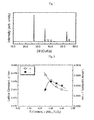
FIG. 1 is an X-ray diffraction pattern of sinteredbody 1; -
FIG. 2 is a graph showing the relationship between the lattice constants (along the a-axis and the c-axis) of the thermoelectric conversion materials ofsintered bodies 1 to 4 and molar ratio x; -
FIG. 3 is a graph showing changes in the Seebeck coefficients ofsintered bodies -
FIG. 4 is a graph showing changes in the electric conductivities ofsintered bodies -
FIG. 5 is a graph showing changes in the thermal conductivities ofsintered bodies -
FIG. 6 is a graph showing changes in the output factors ofsintered bodies -
FIG. 7 is a graph showing changes in the non-dimensional figures of merit ofsintered bodies - The thermoelectric conversion material according to the present invention comprises an oxide containing M1 and oxygen (O).
- M1 is vanadium (V), niobium (Nb) or tantalum (Ta). Each of these may be used individually or in combination with another or more. To increase the output factor α2×σ, it is preferable that part or whole of M1 is Nb, and it is further preferable that M1 is Nb.
- The oxide is represented by the above-mentioned formula (1).
- In the formula (1), y is not less than 1.90, preferably not less than 1.95 and further preferably not less than 1.99, and not more than 2.10, preferably not more than 2.05 and further preferably not more than 2.02. When y is more than 2.10, impurity crystal phases (for example, Nb2O5, etc. M1 is Nb) are produced, whereby the electric conductivity σ tends to be smaller and the Output factor α2×σ is not sufficient. On the other hand, when y is less than 1.90, impurity crystal phases (for example, NbO1.1, etc. M1 is Nb) are produced, whereby the Seebeck coefficient α tends to be smaller and the output factor α2×σ is not sufficient.
- Furthermore, the oxide may further contain M2. The oxide is represented by the above-mentioned formula (2).
- M2 is titanium (Ti), chromium (Cr), manganese (Mn), iron (Fe), cobalt (Co), zirconium (Zr), hafnium (Hf), molybdenum (Mo) or tungsten (W). Each of these may be used individually or in combination with another or more. To improve the output factor α2×σ, it is preferable that part or whole of M2 is Ti, and it is further preferable that M2 is Ti.
- In the formula (2), x is more than 0, preferably not less than 0.20 and further preferably not less than 0.25, and less than 0.5. y is not less than 1.90, preferably not less than 1.95 and further preferably not less than 1.99, and not more than 2.10, preferably not more than 2.05 and further preferably not more than 2.02. When y is more than 2.10, impurity crystal phases (for example, TiNb2C7, Nb2O5, etc. M1 is No and M2 is Ti) are produced, whereby the electric conductivity σ tends to be smaller and the output factor α2×σ is not sufficient. On the other hand, when y is less than 1.90, impurity crystal phases (for example, NbO1.1, TinO2n-1, etc. M1 is Nb and M2 is Ti) are produced, the Seebeck coefficient α tends to be smaller, and the output factor α2×σ is not sufficient.
- The oxide has the crystal structure of a rutile type, an anatase type or a brookite type. It is preferable that the oxide contains a rutile-type crystal structure, and it is further preferable that the oxide is in the form of a rutile-type crystal structure. When the oxide has the crystal structure of a rutile type, the oxide has an excellent energy conversion efficiency even though the oxide is used at high temperatures. It is thus possible to obtain a thermoelectric conversion device that is hardly degraded even after long-term use.
- When the oxide has a rutile-type crystal structure, the rutile-type crystal structure has a lattice constant along the a-axis of not less than 0.4700 nm and not more than 0.4800 nm, and a lattice constant along the c-axis of not less than 0.2980 nm and not more than 0.3200 nm. For example, when M1 is Nb, it is preferable that the the rutile-type crystal structure has a lattice constant along the a-axis of not less than 0.4730 nm and not more than 0.4780 nm, and a lattice constant along the c-axis of not less than 0.2990 nm and not more than 0.3100 nm. The thermoelectric conversion material having the lattice constant along the a-axis and the lattice constant along the c-axis each falling within the above-mentioned ranges tends to have a larger output factor and a lower thermal conductivity. The lattice constants of the rutile-hype crystal structure may be determined by identifying the peaks of the X-ray diffraction of the rutile-type crystal structure by using an X-ray diffraction pattern measured by X-ray diffraction at room temperature and by calculating the lattice constants from the values at the peak positions (2θ) using the least square method (for example, refer to "Crystal Analysis, Universal Program System (II)" edited by Toshio Sakurai, published by the Crystallographic Society of Japan, 1967).
- A thermoelectric conversion material is usually in the form of powder, a sintered body, a thin film or a single crystal, preferably a sintered body. When a thermoelectric conversion material is in the form of a sintered body, the shape and size of the thermoelectric conversion material may be suitably adjusted for a thermoelectric conversion device. For example, the thermoelectric conversion material has the shape of a plate, a cylinder, a disc or a prism.
- A thermoelectric conversion material in the form of a sintered body has a relative density of usually not less than 60%, preferably not less than 80%, further preferably not less than 85%, to ensure strength. The thermoelectric conversion material with a relative density of less than 60% tends to have a decreased electric conductivity σ.
- A thermoelectric conversion material may be produced by using a method of heating a raw material of the thermoelectric conversion material. A thermoelectric conversion material in the shape of a sintered body may be produced by using a method in which the raw material thereof are formed into a green body and the green body is sintered. The thermoelectric conversion material represented by the above-mentioned formula (1) may be produced, for example, by using the method comprising the steps of a1 and b1.
- a1: preparing a raw material containing M1 (at least one selected from the group consisting of V, Nb and Ta) and oxygen (O), the molar amount of O being not less than 1.90 and not more than 2.10 times the molar amount of M1,
- b1: sintering a green body obtained by forming the raw material at a temperature of not less than 900°C and not more than 1700°C under an inert gas atmosphere.
- The thermoelectric conversion material represented by the above-mentioned formula (2) be produced by using the method comprising the steps of a2 and b2.
- a2: preparing a raw material containing M1 (at least one selected from the group consisting of V, Nb and Ta), M2 (at least one selected from the group consisting of Ti, Cr, Mn, Fe, Co, Zr, Hf, Mo and W) and O, the molar amount of M2 being more than 0 and less than 0.5 times the total molar amount of M1 and M2, and the molar amount of O being not less than 1.90 and not more than 2.10 times the total molar amount of M1 and M2,
- b2: sintering a green body obtained by forming the raw material at a temperature of not less than 900°C and not more than 1700°C under an inert gas atmosphere.
- At step a1 and step a2, starting materials containing the metal element (M1 or M2) is weighed and mixed to obtain a mixture so that the mixture has a predetermined composition, whereby a mixture is obtained in which the molar amount of O is not less than 1.90 and not more than 2.10 times the total molar amount of M1 and M2. Examples of the starting materials containing M1 include an oxide, such as Nb2O5, Ta2O5 or V2O5, or a metal, such as Nb, Ta or V. Each of these may be used individually or in combination with another or more. Examples of the starting material containing M2 include an oxide, such as TiO2, Ti2O3, TiO, Cr2O3, MnO2, Fe2O3, Fe3O4, FeO, CO3O4, CoO, ZrO2, HfO2, MoO3 or WO3, or a metal, such as Ti, Cr, Mn, Fe, Co, Zr, Hf, Mo or W. Each of these may be used individually or in combination with another or more. Furthermore, when pre-calcination or calcination described later is performed, instead of the above-mentioned oxides and metals, substances that can be decomposed and/or oxidized to oxides at high temperatures, such as hydroxides, carbonates, nitrates, halides or organic acid salts of the metal element (M1 or M2) may also be used as the starting material containing the metal element (M1 or M2).
- Mixing may be performed using a dry method or a wet method. It is preferable that the mixing is performed by using a method in which a mixture uniformly containing metal elements is obtained. The mixing may be performed with a ball mill, a V-type mixer, a vibrating mill, an attritor, a dyno mill or a dynamic mill.
- For producing a thermoelectric conversion material comprising an oxide represented by formula Nb0.06Ti0.40O2.00, one of favorable compositions, Nb2O5, TiO2 and Ti may be weighed and mixed to obtain a mixture so that the molar ratio of Nb, Ti and O is 0.60:0.40:2.00, and mixture may be used as a raw material. In addition, for producing a thermoelectric conversion material comprising an oxide represented by formula Nb1.00O2.00, Nb2O5 and Nb may be weighed and mixed to obtain a mixture so that the molar ratio of Nb and O is 1.00:2.00, and the mixture may be used as a raw material.
- When the mixture contains hydroxides, carbonates, nitrates, halides or organic acid salts, the mixture may be pre-calcined under an inert gas atmosphere or oxidized gas atmosphere before calcination to remove carbon dioxide, crystal water, etc. A pre-calcination temperature is usually not less than approximately 300°C and not more than a calcination temperature described later, for example, not more than approximately 600°C.
- When the mixture (or pre-calcined mixture) has a molar amount of O of more than 2.10 times the total molar amount of M1 and M2, the mixture may be calcined under a reducing gas atmosphere and used as a raw material. On the other hand, when the mixture) (or pre-calcined mixture) has a molar amount of O of less than 1.90 times the total molar amounts of M1 and M2, the mixture may be calcined under an oxidized gas atmosphere and used as a raw materials. While the mixture (or pre-calcined mixture) has a molar amount of O of not less than 1.90 and not more than 2.10 times the total molar amount of M1 and M2, calcining the mixture under an inert gas atmosphere can reduce deformation during sintering in some cases. Calcination conditions depends on the composition, and a calcination temperature is usually not less than approximately 600°C and not more than approximately 1100°C and a calcination time is usually 0.5 to 24 hours. When the mixture contains hydroxides, carbonates, nitrates, halides or organic acid salts, it is possible to remove carbon dioxide gas, crystal water, etc. by calcination. The calcined mixture may be pulverized and used as a raw material. The pulverization may be performed with, for example, a ball mill, a vibrating mill, an attritor, a dyno mill or a dynamic mill. Furthermore, the mixture may be calcined after it is formed. Using the calcined mixture as a raw material can improve the uniformity of the composition of the sintered body and the uniformity of the structure thereof and reduce the deformation of the sintered body in some times.
- Forking be performed with, for example, a uniaxial press, a cold isostatic press (CIP), a mechanical press, a hot press or a hot isostatic press (HIP). A binder, a dispersing agent and a releasing agent may be used for forming. A green body may have a shape suitable for a thermoelectric conversion device. Examples of the shape include a plate, a cylinder, a disc and a prism.
- Sintering temperature is usually not less than 900°C, preferably not less than 1200°C, further preferably not less than 1250°C and usually not more than 1700°C, preferably not more than 1600°C, further preferably not more than 1500°C. When the sintering temperature is less than 900°C, a solid phase reaction and sintering do not proceed in some cases, and the electric conductivity σ becomes lower depending on the composition in some cases. When the sintering temperature is more than 1700°C, the desired oxide is not obtained because the constituent elements melt and volatilize depending on the composition in some cases, and the thermoelectric conversion material has the reduced figure of merit Z in some cases. When calcination is performed before sintering, the sintering may be performed under an inert gas atmosphere at a temperature higher than the above-mentioned calcination temperature and not higher than 1700°C. The sintering time is usually approximately 0.5 to 24 hours. The inert gas atmosphere during the sintering is, for example, a nitrogen atmosphere or a rare gas atmosphere, preferably an atmosphere containing a rare gas, further preferably a rare gas atmosphere. Ar is used preferably as a rare gas from the viewpoint of operability. The forming and the sintering may be performed simultaneously. In this case, a hot press or a hot isostatic press (HIP) may be used.
- Furthermore, the sintered body may be pulverized, re-sintered and used as a thermoelectric conversion material. The re-sintering may be performed under the same conditions as those of the above-mentioned sintering.
- According to the above-mentioned production method, a thermoelectric conversion material in the form of a sintered body is obtained. The sintered body has a relative density of usually not less than 60%, preferably not less than 80%, further preferably not less than 85%. The relative density of the sintered body can be adjusted depending on the particle size of the material thereof before the sintering, forming pressure, sintering temperature, sintering time, etc.
- Moreover, the sintered body may be coated with an oxygen impermeable film, through the surface of which oxygen hardly passes. The coating can reduce performance degradation to which surface oxidation leads in the thermoelectric conversion material. The oxygen impermeable film is formed of alumina, titania, zirconia, silicas silicon carbide, etc. The coating may be performed using, for example, an aerosol deposition, a spraying or a CVD (chemical vapor deposition).
- The thermoelectric conversion material may be produced by a method comprising a coprecipitation step, a method comprising a hydrothermal step, a method comprising a dry-up step, a method comprising a sputtering step, a method comprising a step in which CVD is performed, a method comprising a sol-gel step, a method comprising an FZ (floating zone melting) step or a method comprising a TSCG (template single crystal growing method) in addition to the above-mentioned method.
- A thermoelectric conversion device comprises the above-mentioned thermoelectric conversion material.
- Since the thermoelectric conversion material is usually an n-type, the thermoelectric conversion device comprises a p-type thermoelectric conversion material, an n-electrode and a p-electrode in addition to the above-mentioned n-type thermoelectric conversion material. As the p-type thermoelectric conversion material, four example, NaCo2O4 or Ca3Co4O9 may be used (
JP-A-9-321346 JP-A-2001-64021 JP-A-5-315657 - The present invention will be illustrated in further detail with reference to Examples. The properties and structure of a thermoelectric conversion material are determined by using the methods described below.
- A sintered body sample was formed to be in the shape of a prism, platinum wires were attached using silver paste, and the electric conductivity was measured using a direct current four-terminal method. The measurement was performed while the temperature was changed in the range of from room temperature to 500°C under nitrogen gas stream.
- R thermocouple wires and platinum wires were attached across both ends of a sample formed to be in the shape of a prism as in the measurement of electric conductivity, and the temperature and the thermoelectromotive force of the sample were measured. The measurements were performed while the temperature was changed in the range of from room temperature to 500°C under nitrogen gas stream. One side of the sample was cooled using a cooling pipe to form a low-temperature portion. The temperatures at both ends of the sample were measured, and the thermoelectromotive force ΔV generated across both end faces of the sample was also measured. The temperature difference ΔT across both ends of the sample was adjusted in the range of from 0.5 to 10°C by adjusting the temperature of the low-temperature portion, and the Seebeck coefficient α was calculated from the slopes of ΔT and ΔV.
- The specific heat and the thermal diffusion factor of a sintered body sample were measured using the laser flash method in vacuum while the temperature was changed in the range of from room temperature to 500°C. A laser thermal constants measuring system TC-7000 manufactured by ULVAC-RIKO, Inc used.
- The crystal structures of a powder sample and a sintered body sample were analyzed with an X-ray diffractometer RINT2500TTR manufactured by RIGAKU Co., Ltd. using the powder X-ray diffraction in which Cubα is used as a radiation source. The lattice constants (along the a-axis and the c-axis) of the rutile-type crystal structure of the sample were determined by identifying the peaks of the X-ray diffraction of the rutile-type crystal structure by using an X-ray diffraction pattern measured by X-ray diffraction and by calculating the lattice constants from the values at the peak positions 2θ using the least square method. The composition of the metal elements in the sample were measured with an X-ray fluorescence spectrometer PW1480 manufactured by Philips Inc. Furthermore, with respect to the amount of oxygen contained in the sample, the increase in weight at the time when the sample was heat treated at a temperature of not less than 1000°C and not more than 1200°C for 48 hours in the atmosphere was wholly calculated as the increased amount of oxygen.
- The density of a sintered body sample was measured using the Archimedes' method. The relative density was calculated on the basis of the density and the lattice constant data determined using the powder X-ray diffraction.
- Niobium oxide (Nb2O5 manufactured by KOJUNDO CHEMICAL LABORATORY CO., LTD.), titanium oxide (TiO2 manufactured by ISHIHARA TECHNO CORPORATION, Trade name: PT-401M) and titanium metal (Ti manufactured by KOJUNDO CHEMICAL LABORATORY CO., LTD.) were used as starting materials. The niobium oxide, titanium oxide and titanium metal were weighed (Table 1) and mixed with a dry ball mill (media: plastic balls) for 6 hours to obtain a mixture of Nb, Ti and O in the ratio of Nb:Ti:O = 0.60:0.40:2.00 (in the molar ratio of Nb2O5:TiO2:Ti = 0.300:0.250:0.150). The mixture was formed into the shape of a disc using a uniaxial press (forming pressure: 200 kg/cm2) and calcined at 1000°C for 3 hours under an argon atmosphere (purity: 99.9995%) to obtain a calcined mixture. The calcined mixture was pulverized using a dry method with a ball mill (media: zirconia balls) to obtain a pulverized mixture (raw material). The raw material was formed into the shape of disc with a uniaxial press (forming pressure: 200 kg/cm2) to obtain a green body. The green body was sintered at 1300°C for 6 hours under an argon atmosphere (purity: 99.9995%) with a sintering furnace to obtain
sintered body 1. - The composition, lattice constants and relative density of
sintered body 1 were shown in Table 2. Thesintered body 1 had the crystal structure of a rutile type, a lattice constants along the a-axis of 0.4740 nm, and a lattice constants along the c-axis of 0.2998 nm. Thesintered body 1 had the color of black and a relative density of 95.5%. - The Seebeck coefficient α, the electric conductivity σ, the thermal conductivity κ, the output factor α2×σ and the non-dimensional figure of merit ZT of
sintered body 1 at 500°C were shown in Table 3. The non-dimensional figure of merit is calculated by multiplying the figure of merit Z (K-1) by absolute temperature T(K). - Except that the amounts of the starting materials were changed as shown in Table 1, the same procedures as in Example 1 was performed to obtain sintered bodies 2 to 4. The properties of sintered bodies 2 to 4 were shown in
Tablets 2 and 3. All of sintered bodies 2 to 4 had the crystal structures of a rutile type. - Except that the amounts of the starting materials were changed as shown in Table 1, the same procedures as in Example 1 was performed to obtain sintered body 5. The properties of sintered body 5 were shown in Tables 2 and 3. Sintered body 5 had the crystal structure of nearly a rutile type.
Table 1 Sintered body Materials and their amounts (molar ratio) Nb1-xTixOy at the time of weighing Nb2O5 TiO2 Ti x y Sintered body 1 0.3000 0.2500 0.1500 0.40 2.00 Sintered body 2 0.3250 0.1875 0.1625 0.35 2.00 Sintered body 30.3500 0.1250 0.1750 0.30 2.00 Sintered body 4 0.3750 0.0625 0.1875 0.25 2.00 Sintered body 5 0.6000 0.2000 0.2000 0.40 1.90 Table 2 Sintered body Result of composition analysis Nb1-xTixOy Lattice constants (nm) Relative density
%x y a-axis c- axis Sintered body 1 0.40 1.99 0.4740 0.2998 95.5 Sintered body 2 0.35 2.00 0.4747 0.3002 91.7 Sintered body 30.30 2.01 0.4763 0.3001 97.8 Sintered body 4 0.25 2.02 0.4776 0.3000 96.8 Sintered body 5 0.40 1.93 0.4737 0.2999 79.6 Table 3 Sintered body Seebeck coefficient Electric conductivity Thermal conductivity Output factor Non-dimensional figure of merit α
(µV/K)σ
(S/m)κ
(W/mK)α2σ
(W/mK2)ZT
(-)Sintered body 1 -122 2.77×10⁴ 2.71 4.15×10⁻⁴ 0.118 Sintered body 2 -120 3.02×10⁴ 2.68 4.34×10⁻⁴ 0.125 Sintered body 3 -128 3.24×10⁴ 2.94 5.29×10⁻⁴ 0.139 Sintered body 4 -115 2.92×10⁴ 2.79 3.83×10⁻⁴ 0.106 Sintered body 5 -114 2.25×10⁴ 2.10 2.90×10⁻⁴ 0.107 - Except that the amounts of the starting materials were changed as shown in Table 4, the same procedures as in Example 1 was performed to obtain sintered bodies 6-8. The properties of sintered bodies 6 to 8 were shown in Tables 5 and 6. All of sintered bodies 6 to 8 had two phases having different crystal structured, Nb1-xTixO2 and TiNb2O7, each of which had a rutile-type crystal structure, and had lower density.
Table 4 Sintered body Materials and their amounts (molar ratio) Nb1-xTixOy at the time of weighing Nb2O5 TiO2 Ti x y Sintered body 6 0.0500 0.9000 0.0000 0.90 2.05 Sintered body 7 0.0750 0.8500 0.0000 0.85 2.08 Sintered body 8 0.1000 0.8000 0.0000 0.80 2.10 Table 5 Sintered body Result of composition analysis Nb1-xTixOy x y Sintered body 6 0.90 2.03 Sintered body 7 0.85 2.06 Sintered body 8 0.80 2.08 Table 6 Sintered body Seebeck coefficient Electric conductivity Thermal conductivity Output factor Non-dimensional figure of merit α
(µV/K)σ
(S/m)κ
(W/mK)α2σ
(W/mK2)ZT
(-)Sintered body 6 -288 1.11×10³ 1.52 9.21×10⁻⁵ 0.047 Sintered body 7 -500 3.78×10² 1.97 9.44×10⁻⁵ 0.037 Sintered body 8 -349 1.82×10² 2.18 2.22×10⁻⁵ 0.008 - According to the present invention, a thermoelectric conversion material having a large output factor α2×σ and a large figure of merit Z is obtained.
Claims (10)
- A thermoelectric conversion material comprising an oxide represented by formula (1):
M1Oy (1)
where M1 is at least one selected from the group consisting of V, Nb and Ta, and 1.90≤y≤2.10. - A thermoelectric conversion material comprising an oxide represented by formula (2):
M1 1-xM2 xOy (2)
where M1 is at least one selected from the group consisting of V, Nb and Ta, M2 is at least one selected from the group consisting of Ti, Cr, Mn, Fe, Co, Zr, Hf, Mo and W,
0<x<0.5, and 1.90≤y≤2.10. - The thermoelectric conversion material according to claim 1 or 2, wherein the oxide has a rutile-type crystal structure.
- The thermoelectric conversion material according to claim 3, wherein the lattice constant along the a-axis of the rutile-type crystal structure is not less than 0.4700 nm and not more than 0.4800 nm, and the lattice constant along the c-axis thereof is not less than 0.2980 nm and not more than 0.3200 nm.
- The thermoelectric conversion material, according to any one of claims 1 to 4, wherein M1 is Nb.
- The thermoelectric conversion material according to any one of claims 1 to 5, wherein the material is in the form of a sintered body and the relative density of the sintered body is not less than 60%.
- The thermoelectric conversion material according to claim 6, wherein the surface of the sintered body is coated with an oxygen impermeable film.
- A thermoelectric conversion device having said thermoelectric conversion material according to any one of claims 1 to 7.
- A method for producing said thermoelectric conversion material according to claim 1, comprising the steps of a1 and b1.a1: preparing a raw material containing M1 (at least one selected from the group consisting of V, Nb and Ta) and O, the molar amount of O being not less than 1.90 and not more than 2.10 times the molar amount of M1,b1: sintering a green body obtained by forming the raw material at a temperature of not less than 900°C and not more than 1700°C under an inert gas atmosphere.
- A method for producing said thermoelectric conversion material according to claim 2, comprising the step of a2 and b2,a2: preparing a raw material containing M1 (at least one selected from the group consisting of V, Nb and Ta), M2 (at least one selected from the group consisting of Ti, Cr, Mn, Fe, Co, Zr, Hf, Mo and W) and O, the molar amount of M2 being more than 0 and less than 0.5 times the total molar amount of M1 and M2, and the molar amount of O being not less than 1.90 and not more than 2.10 times the total molar amount of M1 and M2,b2: sintering a green body obtained by forming the raw material at a temperature of not less than 900°C and not more than 1700°C under an inert gas atmosphere.
Applications Claiming Priority (2)
| Application Number | Priority Date | Filing Date | Title |
|---|---|---|---|
| JP2007104643A JP2008263056A (en) | 2007-04-12 | 2007-04-12 | Thermoelectric conversion material and method for producing the same |
| PCT/JP2008/057457 WO2008133153A1 (en) | 2007-04-12 | 2008-04-10 | Thermoelectric conversion material, method for production thereof, and thermoelectric conversion element |
Publications (2)
| Publication Number | Publication Date |
|---|---|
| EP2136415A1 true EP2136415A1 (en) | 2009-12-23 |
| EP2136415A4 EP2136415A4 (en) | 2012-03-14 |
Family
ID=39925609
Family Applications (1)
| Application Number | Title | Priority Date | Filing Date |
|---|---|---|---|
| EP08740527A Withdrawn EP2136415A4 (en) | 2007-04-12 | 2008-04-10 | THERMOELECTRIC CONVERSION MATERIAL, CORRESPONDING PRODUCTION METHOD, AND THERMOELECTRIC CONVERSION ELEMENT |
Country Status (6)
| Country | Link |
|---|---|
| US (1) | US20100140568A1 (en) |
| EP (1) | EP2136415A4 (en) |
| JP (1) | JP2008263056A (en) |
| CN (1) | CN101669222B (en) |
| TW (1) | TW200849681A (en) |
| WO (1) | WO2008133153A1 (en) |
Cited By (1)
| Publication number | Priority date | Publication date | Assignee | Title |
|---|---|---|---|---|
| US20130126800A1 (en) * | 2011-11-17 | 2013-05-23 | Monika Backhaus-Ricoult | Niobium oxide-based thermoelectric composites |
Families Citing this family (8)
| Publication number | Priority date | Publication date | Assignee | Title |
|---|---|---|---|---|
| US20100163091A1 (en) * | 2008-12-30 | 2010-07-01 | Industrial Technology Research Institute | Composite material of complex alloy and generation method thereof, thermoelectric device and thermoelectric module |
| DE102010050395A1 (en) * | 2010-11-03 | 2012-05-03 | Emitec Gesellschaft Für Emissionstechnologie Mbh | Thermoelectric module for a thermoelectric generator of a vehicle |
| JP5537402B2 (en) * | 2010-12-24 | 2014-07-02 | 株式会社日立製作所 | Thermoelectric conversion material |
| CN102627443A (en) * | 2012-04-17 | 2012-08-08 | 中国科学院青海盐湖研究所 | Preparation method of Ca3Co4O9/Ag composite ceramic thermoelectric material with special morphology |
| JP6118679B2 (en) * | 2013-08-02 | 2017-04-19 | 株式会社日本自動車部品総合研究所 | Gas sensor element and gas sensor |
| WO2016136773A1 (en) * | 2015-02-27 | 2016-09-01 | 株式会社村田製作所 | Vanadium dioxide |
| US20180209066A1 (en) * | 2015-07-23 | 2018-07-26 | Panasonic Corporation | Rutile-type niobium oxynitride, method for producing same, and semiconductor structure |
| JP7523028B2 (en) * | 2018-10-17 | 2024-07-26 | パナソニックIpマネジメント株式会社 | Thermoelectric conversion material and method for obtaining electric power using the thermoelectric conversion material |
Family Cites Families (7)
| Publication number | Priority date | Publication date | Assignee | Title |
|---|---|---|---|---|
| JP2005276959A (en) * | 2004-03-24 | 2005-10-06 | National Institute Of Advanced Industrial & Technology | Thermoelectric conversion material, thermoelectric conversion element, and thermoelectric power generation element using the same |
| JP2006062951A (en) * | 2004-07-27 | 2006-03-09 | Sumitomo Chemical Co Ltd | Thermoelectric conversion material and method for producing the same |
| WO2006011581A1 (en) * | 2004-07-27 | 2006-02-02 | Sumitomo Chemical Company, Limited | Thermoelectric conversion material and process for producing the same |
| JP2006100683A (en) * | 2004-09-30 | 2006-04-13 | Sumitomo Chemical Co Ltd | Titanium oxide thermoelectric conversion material |
| CN100357223C (en) * | 2005-07-19 | 2007-12-26 | 北京科技大学 | N type cobalt niobate oxide thermoelectric material and preparation method thereof |
| JP4844043B2 (en) * | 2005-08-18 | 2011-12-21 | 住友化学株式会社 | Thermoelectric conversion material and method for producing the same |
| JP4967772B2 (en) * | 2006-08-24 | 2012-07-04 | 住友化学株式会社 | Thermoelectric conversion material and method for producing the same |
-
2007
- 2007-04-12 JP JP2007104643A patent/JP2008263056A/en active Pending
-
2008
- 2008-04-09 TW TW097112797A patent/TW200849681A/en unknown
- 2008-04-10 EP EP08740527A patent/EP2136415A4/en not_active Withdrawn
- 2008-04-10 CN CN2008800114768A patent/CN101669222B/en not_active Expired - Fee Related
- 2008-04-10 WO PCT/JP2008/057457 patent/WO2008133153A1/en not_active Ceased
-
2009
- 2009-04-10 US US12/594,831 patent/US20100140568A1/en not_active Abandoned
Non-Patent Citations (3)
| Title |
|---|
| FISHER ET AL: "Electrical and seebeck effect measurements in Nb doped VO2", JOURNAL OF PHYSICS AND CHEMISTRY OF SOLIDS, PERGAMON PRESS, LONDON, GB, vol. 43, no. 3, 1 January 1982 (1982-01-01), pages 205-211, XP024581731, ISSN: 0022-3697, DOI: 10.1016/0022-3697(82)90180-9 [retrieved on 1982-01-01] * |
| LAGNEL F ET AL: "Electron Transport in Amorphous (Ti, Nb)O2 Solid Solutions", PHYSICA STATUS SOLIDI. B, BASIC RESEARCH, AKADEMIE VERLAG, BERLIN, DE, vol. 151, no. 2, 1 February 1989 (1989-02-01), pages 531-543, XP008120082, ISSN: 0370-1972, DOI: 10.1002/PSSB.2221510213 [retrieved on 2006-02-19] * |
| See also references of WO2008133153A1 * |
Cited By (1)
| Publication number | Priority date | Publication date | Assignee | Title |
|---|---|---|---|---|
| US20130126800A1 (en) * | 2011-11-17 | 2013-05-23 | Monika Backhaus-Ricoult | Niobium oxide-based thermoelectric composites |
Also Published As
| Publication number | Publication date |
|---|---|
| US20100140568A1 (en) | 2010-06-10 |
| JP2008263056A (en) | 2008-10-30 |
| CN101669222A (en) | 2010-03-10 |
| EP2136415A4 (en) | 2012-03-14 |
| CN101669222B (en) | 2012-08-01 |
| WO2008133153A1 (en) | 2008-11-06 |
| TW200849681A (en) | 2008-12-16 |
Similar Documents
| Publication | Publication Date | Title |
|---|---|---|
| US20100140568A1 (en) | Thermoelectric conversion material, method for producing the same, and thermoelectric conversion device | |
| EP2088634A1 (en) | Thermo-electric converting material, process for producing the same, thermo-electric converting element, and method of heightening strength of thermo-electric converting material | |
| JP4967772B2 (en) | Thermoelectric conversion material and method for producing the same | |
| Park et al. | Effect of TiO2 on high-temperature thermoelectric properties of ZnO | |
| US20120145214A1 (en) | Thermoelectric conversion material, and thermoelectric conversion module using same | |
| EP2096687A1 (en) | Thermoelectric conversion material and thermoelectric conversion element | |
| US20100327238A1 (en) | Sintered body and thermoelectric material | |
| EP1895603A1 (en) | Thermoelectric conversion material, method for production thereof and thermoelectric conversion element | |
| CN101558504A (en) | Thermo-electric converting material, process for producing the same, thermo-electric converting element, and method of heightening strength of thermo-electric converting material | |
| JPH08236818A (en) | Thermoelectric conversion material | |
| CN101523627A (en) | Thermoelectric material, method for producing the same, and thermoelectric converter | |
| EP1791191A1 (en) | Thermoelectric conversion material and process for producing the same | |
| Ito et al. | Effects of TiB2 addition on spark plasma sintering and thermoelectric performance of Y-doped SrTiO3 synthesized by polymerized complex process | |
| JP2006062951A (en) | Thermoelectric conversion material and method for producing the same | |
| JP4876721B2 (en) | Thermoelectric conversion material and method for producing the same | |
| CN101983437A (en) | Sintered compact and thermoelectric conversion material | |
| Park et al. | Improved thermoelectric properties by adding Al for Zn in (ZnO) mIn2O3 | |
| JP4844043B2 (en) | Thermoelectric conversion material and method for producing the same | |
| JP2023013300A (en) | Actuator material, actuator element and oxide | |
| JP2008300759A (en) | Thermoelectric conversion material | |
| JP3586716B2 (en) | Composite oxide with high thermoelectric conversion efficiency | |
| JP2003282965A (en) | Highly oriented polycrystalline ceramics, method for producing the same, and thermoelectric conversion element | |
| JP2003048776A (en) | NaCo-based oxide sintered body and method for producing the same | |
| 张辉 | Synthesis and Characterization of a New Fe_2O_3 Pillared Triple-layered Perovskite KSr_2Nb_3O_ (10) | |
| WO2007138719A1 (en) | Thermoelectric material |
Legal Events
| Date | Code | Title | Description |
|---|---|---|---|
| PUAI | Public reference made under article 153(3) epc to a published international application that has entered the european phase |
Free format text: ORIGINAL CODE: 0009012 |
|
| 17P | Request for examination filed |
Effective date: 20091019 |
|
| AK | Designated contracting states |
Kind code of ref document: A1 Designated state(s): AT BE BG CH CY CZ DE DK EE ES FI FR GB GR HR HU IE IS IT LI LT LU LV MC MT NL NO PL PT RO SE SI SK TR |
|
| DAX | Request for extension of the european patent (deleted) | ||
| A4 | Supplementary search report drawn up and despatched |
Effective date: 20120214 |
|
| RIC1 | Information provided on ipc code assigned before grant |
Ipc: H01L 35/22 20060101AFI20120208BHEP Ipc: C04B 35/00 20060101ALI20120208BHEP Ipc: C01G 33/00 20060101ALI20120208BHEP Ipc: C04B 41/87 20060101ALI20120208BHEP Ipc: H01L 35/34 20060101ALI20120208BHEP |
|
| STAA | Information on the status of an ep patent application or granted ep patent |
Free format text: STATUS: THE APPLICATION IS DEEMED TO BE WITHDRAWN |
|
| 18D | Application deemed to be withdrawn |
Effective date: 20120913 |