EP2136377B1 - Systeme und Verfahren zum Sammeln von Daten in einem Fahrzeug - Google Patents
Systeme und Verfahren zum Sammeln von Daten in einem Fahrzeug Download PDFInfo
- Publication number
- EP2136377B1 EP2136377B1 EP09163174A EP09163174A EP2136377B1 EP 2136377 B1 EP2136377 B1 EP 2136377B1 EP 09163174 A EP09163174 A EP 09163174A EP 09163174 A EP09163174 A EP 09163174A EP 2136377 B1 EP2136377 B1 EP 2136377B1
- Authority
- EP
- European Patent Office
- Prior art keywords
- data collection
- fiber optic
- data
- vehicle
- node
- Prior art date
- Legal status (The legal status is an assumption and is not a legal conclusion. Google has not performed a legal analysis and makes no representation as to the accuracy of the status listed.)
- Active
Links
Images


Classifications
-
- G—PHYSICS
- G07—CHECKING-DEVICES
- G07C—TIME OR ATTENDANCE REGISTERS; REGISTERING OR INDICATING THE WORKING OF MACHINES; GENERATING RANDOM NUMBERS; VOTING OR LOTTERY APPARATUS; ARRANGEMENTS, SYSTEMS OR APPARATUS FOR CHECKING NOT PROVIDED FOR ELSEWHERE
- G07C7/00—Details or accessories common to the registering or indicating apparatus of groups G07C3/00 and G07C5/00
-
- G—PHYSICS
- G02—OPTICS
- G02B—OPTICAL ELEMENTS, SYSTEMS OR APPARATUS
- G02B6/00—Light guides; Structural details of arrangements comprising light guides and other optical elements, e.g. couplings
- G02B6/44—Mechanical structures for providing tensile strength and external protection for fibres, e.g. optical transmission cables
- G02B6/4401—Optical cables
- G02B6/4415—Cables for special applications
- G02B6/4416—Heterogeneous cables
-
- G—PHYSICS
- G02—OPTICS
- G02B—OPTICAL ELEMENTS, SYSTEMS OR APPARATUS
- G02B6/00—Light guides; Structural details of arrangements comprising light guides and other optical elements, e.g. couplings
- G02B6/44—Mechanical structures for providing tensile strength and external protection for fibres, e.g. optical transmission cables
- G02B6/4401—Optical cables
- G02B6/4429—Means specially adapted for strengthening or protecting the cables
- G02B6/443—Protective covering
- G02B6/4432—Protective covering with fibre reinforcements
-
- H—ELECTRICITY
- H01—ELECTRIC ELEMENTS
- H01B—CABLES; CONDUCTORS; INSULATORS; SELECTION OF MATERIALS FOR THEIR CONDUCTIVE, INSULATING OR DIELECTRIC PROPERTIES
- H01B11/00—Communication cables or conductors
- H01B11/22—Cables including at least one electrical conductor together with optical fibres
Definitions
- the field of the invention relates generally to data collection and more specifically to the use of fiber optics for collecting data to support Integrated Vehicle Health Management (IVHM).
- IVHM Integrated Vehicle Health Management
- IVHM is the collection and processing of data to determine (diagnosis) and predict (prognosis) an operational status (i.e., health) of a vehicle system or subsystem, and enable the mitigation of adverse events during operation.
- Hardware faults and failures are typically difficult to detect, diagnose and mitigate with existing technologies during operation.
- the time needed to address the faults and failures impacts mission availability.
- computer software related risks represent equally serious threats due to increased system complexity and a higher reliance upon automation.
- Some known IVHM systems may be used on-board aircraft to support flight critical processes and decisions, and include hardware and software elements that support the maintenance and logistics processes and decisions, but that do not substantially impact mission or flight critical processes or decisions.
- Some known IVHM solutions include passively monitoring avionics data bus traffic or capturing and processing subsystems data within flight critical processors at the subsystem or core processor level.
- Known data acquisition and collection methods do not support more advanced IVHM functions, particularly health prediction or prognostics.
- Avionics data buses handle the data necessary to control the vehicle and generally do not support access to higher fidelity data within subsystems controllers, nor do such data buses support implementation of higher bandwidth 'IVHM sensors' that monitor vibration, current or structural harmonics. The development and validation costs associated with embedding such support critical IVHM processing within flight critical processors is may be prohibitive.
- FR 2659159 discloses a cable arrangement for connecting a tractor unit with a trailer unit.
- information may pass between the tractor and trailer units in relation to maintenance levels, distance travelled and other such activity to do with transport. This information may be passed along a fibre optic cable.
- EP 0095254 discloses a composite cable wherein an optical fibre and a plurality of conductors are arranged integrally and bound together by means of an insulating material.
- US 4365865 discloses a hybrid cable construction of a plurality of optical fibres and metal conductors wound at a common lay angle. At least the metal conductors are sheathed by a fibre reinforced resin and are prevented thereby from hockling.
- US 5551484 discloses a pipeline and monitoring system.
- a multi-layered liner for lining a pipeline which has an external jacket, an interior liner, a woven intermediate layer between the external jacket and the interior liner is disclosed.
- At least one optical fibre is in the woven intermediate liner for the purposes of monitoring stress or for communication, and a capacitance leak detection circuit is also in the multi-layer liner for the purpose of detecting leaks in the multi-layered liner.
- One aspect is directed to a data collection system of a vehicle as defined in claim 1.
- Figure 1 is a schematic of an exemplary data collection system.
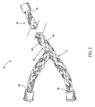
- Figure 2 is a perspective view of an exemplary fiber optic embedded wire system used in the data collection system shown in Figure 1 .
- Figure 3 is a partial internal view of the fiber optic embedded wire system shown in Figure 2 .
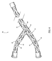
- Figure 4 is a perspective view of an alternative fiber optic embedded wire system.
- Figure 5 is a flow diagram of an exemplary method of data collection that may use the system shown in Figure 1 .
- Figure 1 is a schematic of an exemplary data collection system 10.
- system 10 is installed within an aircraft (not shown) to support flight critical processes and decisions, and maintenance and logistics processes and decisions.
- System 10 includes a core processor 12 that is operatively coupled to a data collection node 14 via a wiring harness 16. At least a portion of the operative coupling of wiring harness 16 includes a fiber optic embedded wiring system, as described in more detail herein.
- core processor 12 may be operatively coupled to a subsystem node 18 alone or in combination with data collection node 14.
- subsystem node 18 is an accelerometer configured to measure vibration in a subsystem component (not shown).
- subsystem node 18 may be any sensor configured to measure a desired system quantity.
- system 10 may include a plurality of subsystem nodes 18 that are associated with various subsystem components.
- data collection node 14 includes antenna 22 that enables data collection node 14 to wirelessly communicate with a first sensor node 24 positioned within the vehicle at a physically separate location.
- First sensor node 24 includes an antenna 26 that enables wireless communications, and may include, without limitation, a strain gauge (not shown), an accelerometer (not shown) configured to sense vibration, or any other sensor configured to passively collect data from a desired system or subsystem.
- Subsystem node 18 and sensor nodes 24, 28 generally provide IVHM data through various channels as described herein, including via a wire, wirelessly, or via fiber optic connection.
- a second sensor node 28 may be provided that is configured to passively collect data from a vehicle sub-system, and is communicatively coupled to data collection node via a wiring harness 29. Data collection node is then configured to interpret, or simply forward, the data provided by the sensor nodes 24, 28 to the core processor 12. The data is transmitted via the embedded fiber optics within wiring harness 16.
- wiring harness 29 includes a fiber optic communications channel (not shown).
- Figure 2 is a perspective view of an exemplary fiber optic embedded wire system 30 used in the data collection system shown in Figure 1
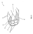
- Figure 3 is a partial internal view of the fiber optic embedded wire system 30 shown in Figure 2
- wiring system 30 includes a wire harness 32 that includes multiple, individual conductors 34 (as shown in Figure 3 ) held in a group via an overbraid 35 for use in communicatively coupling core processor 12 to components within data collection system 10, as shown in Figure 1 .
- wiring system 30 communicatively couples core processor 12 to at least one of data collection node 14 and subsystem node 18 such that a wire first end 36 is coupled to core processor 12, a wire second end 38 is coupled to data collection node 14, and a wire third end 40 is coupled to sub-system node 18.
- wire harness 32 is any group of conductors within an overbraid 35 that enables the data collection system 10 to function as described herein.
- core processor 12 may be coupled to subsystem node 18 and data collection node with two separate, fiber optic embedded conductors.
- a plurality of fiber optic cables 42 is integrally woven into overbraid 35.
- a first group of three fiber optic cables 46 and a second group of three fiber optic cables 48 are integrally woven into overbraid 35. This forms a redundancy in the fiber optic communications channels embedded within wiring system 30.
- the first group 46 and the second group 48 are offset in overbraid 35 such that each lie within a different grouping of strands 49 that form overbraid 35.
- any number of fiber optic cables may be integrally woven into overbraid 35 such that data collection system 10 may function as described herein.
- fiber optic cables 42 are woven into overbraid 35 such that fiber optic cables 42 pass from an interior 37 of overbraid 35 (shown in Figure 3 ) to an external 39 of overbraid 35 (shown in Figure 3 ).
- fiber optic cables 42 are intermittently woven within overbraid 35 such that data collection system 10 may function as described herein.
- Figure 4 is a perspective view of an alternative fiber optic embedded wire system 50 includes a wire harness 52 that includes multiple, individual conductors 34 (as shown in Figure 3 ) held in a group via an overbraid 55 for use in communicatively coupling core processor 12 to components within data collection system 10, as shown in Figure 1 .
- a plurality of fiber optic cables 56 extends substantially longitudinally and substantially linearly throughout overbraid 55.
- a first group of three fiber optic cables 58, a second group of three fiber optic cables 60, and a third group of three fiber optic cables 62 are spaced circumferentially around overbraid 54 and are inter-woven within overbraid 55 such that each group of fiber optic cables 58, 60 and 62 extends substantially linearly throughout overbraid 55. This forms a redundancy in the fiber optic communications channels embedded within wiring system 50.
- any number of groups of fiber optic cables may be provided that allows the data collection system 10 to function as described herein.
- FIG. 5 is a flow diagram of an exemplary method 200 of data collection that may use the system shown in Figure 1 .
- a core processor is coupled 210 to a data collection node as described herein.
- a wiring system is provided for use in communicatively coupling a core processor to at least one of a data collection node and a subsystem node.
- a wire harness is provided that includes multiple, individual conductors grouped together within an overbraid that is sized and oriented to receive the wire harness therein.
- wiring system includes any grouping of conductors within an overbraid that enables the data collection system to function as described herein.
- Coupling 210 a core processor to a data collection node via a wiring system further includes integrally weaving at least one fiber optic cable within the overbraid to provide a communications channel from the core processor to a data collection node that provides data relating to vehicle and/or system status, as well as issuing a fault notice should the fiber optics becomes severed during operations, for example, due to wear-and-tear on the wires.
- a plurality of fiber optic cables is arranged in groups having three fiber optic cables each and each group is then integrally woven within the overbraid. This forms a redundancy in the fiber optic communications channels embedded within wiring system.
- coupling 210 the core processor to the data collection node includes providing a first group of three fiber optic cables, a second group of three fiber optic cables, and a third group of fiber optic cables spaced circumferentially about the overbraid and interweaving each group of fiber optic cables within the overbraid such that each fiber optic cable extends substantially linearly throughout the overbraid. This forms a redundancy in the fiber optic communications channels embedded within wiring system.
- Data is then acquired 220 by the data collection node from a sensor node.
- the data is acquired wireless and includes high bandwidth, IVHM data associated with subsystem operation, as described herein.
- the data may be acquired by the data collection node via any wiring assembly, and may include any avionics, system or subsystem data that enables the core processor to function as described herein.
- Data is then transmitted 230 from the data collection node to the core processor via the fiber optic cables.
- a typical overbraided wire operatively connects the data collection node with the core processor.
- fiber optic cables are integrally woven into the cable overbraid to enable transmission of the data.
- the fiber optic cables may be interwoven in any fashion that allows the data collection system to function as described herein.
- the core processor performs the task of predicting 240 a status of the vehicle or vehicle system based upon the IVHM data that was transmitted 230 from the data collection node or subsystem node.
- the prediction 240 is continuously executed during vehicle operation and the data is then saved in the core processor for later extraction.
- the core processor will then transmit 250 the prediction externally. This transmission 250 may occur when requested by an outside source, or may be programmed to periodically dump the data and prediction to the outside source.
- processors and computer programs may also apply to any system and/or program that is configured to determine (diagnosis) and/or predict (prognosis) the health of a vehicle system or subsystem, and enable the mitigation of adverse events during operation.
- processor is not limited to just those integrated circuits referred to in the art as processors, but broadly refers to computers, processors, microcontrollers, microcomputers, programmable logic controllers, application specific integrated circuits, and other programmable circuits.
- the processor may be part of a computer that may include a device, such as; a floppy disk drive or compact disc-read-only memory (CD-ROM) drive, for reading data from a computer-readable medium, such as a floppy disk, a CD-ROM, a magneto-optical disk (MOD), or a digital versatile disc (DVD).
- a device such as; a floppy disk drive or compact disc-read-only memory (CD-ROM) drive, for reading data from a computer-readable medium, such as a floppy disk, a CD-ROM, a magneto-optical disk (MOD), or a digital versatile disc (DVD).
- CD-ROM compact disc-read-only memory
- Exemplary embodiments of data collection systems used in aviation industry are described in detail herein.
- the disclosed data collection systems include wiring systems fabricated with fiber optics, and may be implemented to facilitate a low cost, low footprint, dual use approach to accessing support critical IVHM data.
- this design is particularly useful to legacy upgrades because 'normal' wire bundles can be replaced with fiber optic embedded wiring systems that can then be plugged into upgraded subsystems with an IVHM interface.
- Existing solutions rely on using the resources of existing flight and mission critical communication, storage and processing resources for support critical IVHM. The cost of development and implementation in a mission or flight critical environment may be prohibitive for even the major subsystems, such as propulsion systems, since the current avionics designs do not address support critical IVHM requirements.
Landscapes
- Physics & Mathematics (AREA)
- General Physics & Mathematics (AREA)
- Optics & Photonics (AREA)
- Arrangements For Transmission Of Measured Signals (AREA)
- Electric Propulsion And Braking For Vehicles (AREA)
Claims (7)
- Datenerfassungssystem (10) eines Fahrzeugs, wobei das Datenerfassungssystem aufweist:einen ersten Datenerfassungsknoten (14), der konfiguriert ist, um Daten von einem Fahrzeuguntersystem zu erhalten;einen Prozessor (12), der kommunikativ mit dem Datenerfassungsknoten über ein Verdrahtungssystem (30) verbunden ist, wobei das Verdrahtungssystem eine Vielzahl von Leitern (34), wenigstens ein Glasfaserkabel (42) und eine Abschirmung (35), die die Vielzahl von Leitern umgibt, aufweist,dadurch gekennzeichnet, dassdie Abschirmung das wenigstens eine Glasfaserkabel so aufweist, dass es integral in der Abschirmung verflochten und konfiguriert ist, um Daten, die sich auf den Betriebsstatus des Fahrzeuguntersystems beziehen, zwischen dem Prozessor und dem ersten Datenerfassungsknoten zu übertragen, wobei eine Abnutzung des Leitungsnetzes dadurch feststellbar ist, dass das wenigstens eine Glasfaserkabel getrennt wird.
- Datenerfassungssystem (10) nach Anspruch 1, das des Weiteren einen optischen Transceiver aufweist, der mit dem Prozessor (12) verbunden ist, wobei der Datenerfassungsknoten (14) einen optischen Transceiver aufweist, wobei die optischen Transceiver konfiguriert sind, um über das wenigstens eine Glasfaserkabel (42) zu kommunizieren.
- Datenerfassungssystem (10) nach Anspruch 1, das des Weiteren einen zweiten Datenerfassungsknoten aufweist, der sich in dem Fahrzeug befindet und konfiguriert ist, um Daten an den ersten Datenerfassungsknoten (14) über wenigstens eines eines elektrischen Leiters, einer drahtlosen Schnittstelle und einer Glasfaserschnittstelle drahtlos oder über das wenigstens eine Glasfaserkabel (42) zu übertragen.
- Datenerfassungssystem (10) nach Anspruch 1, wobei das wenigstens eine Glasfaserkabel (42) des Weiteren eine Vielzahl optischer Fasern aufweist, die konfiguriert sind, um redundante optische Pfade (46, 48) zwischen dem ersten Datenerfassungsknoten (14) und dem Prozessor (12) vorzusehen.
- Datenerfassungssystem (10) nach Anspruch 1, das des Weiteren einen Untersystemknoten (18) aufweist, der sich in dem Fahrzeug befindet und konfiguriert ist, um Daten, die sich auf den Betriebsstatus des Fahrzeuguntersystems beziehen, über das wenigstens eine Glasfaserkabel (42) zu übertragen.
- Datenerfassungssystem (10) nach Anspruch 5, wobei der zweite Datenerfassungsknoten konfiguriert ist, um Daten drahtlos an den ersten Datenerfassungsknoten (14) zu übertragen.
- Datenerfassungssystem (10) nach Anspruch 1, wobei der Prozessor (12) programmiert ist zum:Feststellen des aktuellen Status wenigstens des Fahrzeugs oder des Fahrzeuguntersystems mittels Daten, die von dem ersten Datenerfassungsknoten (14) empfangen wurden (230);Vorhersagen (240) des Status wenigstens des Fahrzeugs oder des Fahrzeuguntersystems mittels Daten, die von dem ersten Datenerfassungsknoten empfangen wurden; undÜbertragen (250) eines Statusberichts unter Verwendung der Statusvorhersage an einen Benutzer über eine Benutzerschnittstelle.
Applications Claiming Priority (1)
| Application Number | Priority Date | Filing Date | Title |
|---|---|---|---|
| US12/141,806 US8116940B2 (en) | 2008-06-18 | 2008-06-18 | Systems and method for collecting data in a vehicle |
Publications (2)
| Publication Number | Publication Date |
|---|---|
| EP2136377A1 EP2136377A1 (de) | 2009-12-23 |
| EP2136377B1 true EP2136377B1 (de) | 2012-03-07 |
Family
ID=40940093
Family Applications (1)
| Application Number | Title | Priority Date | Filing Date |
|---|---|---|---|
| EP09163174A Active EP2136377B1 (de) | 2008-06-18 | 2009-06-18 | Systeme und Verfahren zum Sammeln von Daten in einem Fahrzeug |
Country Status (3)
| Country | Link |
|---|---|
| US (1) | US8116940B2 (de) |
| EP (1) | EP2136377B1 (de) |
| AT (1) | ATE548715T1 (de) |
Families Citing this family (13)
| Publication number | Priority date | Publication date | Assignee | Title |
|---|---|---|---|---|
| US20120080225A1 (en) * | 2010-09-30 | 2012-04-05 | Apple Inc. | Cable for electrical and optical transmission |
| USD695975S1 (en) * | 2011-09-23 | 2013-12-17 | Jennifer Beinke | Adjustable collar |
| USD695970S1 (en) * | 2011-09-23 | 2013-12-17 | Jennifer Beinke | Leash |
| US9235937B1 (en) | 2013-06-05 | 2016-01-12 | Analog Devices, Inc. | Mounting method for satellite crash sensors |
| US9218694B1 (en) | 2013-08-12 | 2015-12-22 | The Boeing Company | Recommendations for time to replace parts on machines |
| WO2015183364A2 (en) | 2014-05-09 | 2015-12-03 | Sikorsky Aircraft Corporation | Method and apparatus for condition based maintenance of fiber networks on vehicles |
| BR102015011128A2 (pt) | 2014-05-19 | 2017-11-28 | R. Byrne Norman | Branched electric system and high seat density area |
| EP3287990B1 (de) | 2016-08-25 | 2020-09-30 | Airbus Operations GmbH | Datenerfassungssystem und verfahren zur datenerfassung |
| US10425236B2 (en) | 2016-10-05 | 2019-09-24 | Norman R. Byrne | Intelligent electrical power distribution system |
| WO2018065970A2 (en) | 2016-10-07 | 2018-04-12 | Byrne Norman R | Rugged weather resistant power distribution |
| JP7043446B2 (ja) * | 2019-03-18 | 2022-03-29 | 矢崎総業株式会社 | 車両通信システム |
| US11303079B2 (en) | 2019-05-28 | 2022-04-12 | Norman R. Byrne | Modular electrical system |
| CA3082616A1 (en) | 2019-06-07 | 2020-12-07 | Norman R. Byrne | Electrical power distribution system |
Citations (2)
| Publication number | Priority date | Publication date | Assignee | Title |
|---|---|---|---|---|
| US5551484A (en) * | 1994-08-19 | 1996-09-03 | Charboneau; Kenneth R. | Pipe liner and monitoring system |
| DE102004042101A1 (de) * | 2004-08-30 | 2006-03-09 | Deutsche Bahn Ag | Energieversorgung und Signalübertragung für Messtechnik auf Hochspannungspotential |
Family Cites Families (21)
| Publication number | Priority date | Publication date | Assignee | Title |
|---|---|---|---|---|
| US3984622A (en) * | 1976-02-20 | 1976-10-05 | Southern Weaving Company | Multi-conductor cable harness with woven breakout cover and method of making same |
| US4365865A (en) | 1981-01-30 | 1982-12-28 | Sea-Log Corporation | Hybrid cable construction |
| EP0095254A3 (de) | 1982-05-27 | 1986-02-19 | Nissan Motor Co., Ltd. | Elektrooptisches Kabel |
| US4804806A (en) * | 1987-06-15 | 1989-02-14 | Woven Electronics Corporation | Woven electrical transmission cable for rapid aircraft repair and method |
| FR2659159B1 (fr) | 1990-03-01 | 1993-12-10 | Rino Colonnello | Dispositif de stockage sur un vehicule tracte d'informations relatives a celui-ci, en particulier pour son identification ou sa reconnaissance automatique. |
| US5917977A (en) * | 1997-09-16 | 1999-06-29 | Siecor Corporation | Composite cable |
| US6265880B1 (en) | 1999-06-15 | 2001-07-24 | The United States Of America As Represented By The Secretary Of The Air Force | Apparatus and method for detecting conduit chafing |
| US6907416B2 (en) * | 2001-06-04 | 2005-06-14 | Honeywell International Inc. | Adaptive knowledge management system for vehicle trend monitoring, health management and preventive maintenance |
| US6561454B1 (en) * | 2002-05-08 | 2003-05-13 | Lockheed Martin Corporation | Network hub for a reconfigurable data network having physical transmission media |
| US7386612B2 (en) * | 2003-06-18 | 2008-06-10 | Honeywell International Inc. | Method and apparatus for disambiguating transmit-by-exception telemetry from a multi-path, multi-tier network |
| US7356612B2 (en) * | 2003-06-18 | 2008-04-08 | Honeywell International Inc. | Method and apparatus for storing and retrieving data related to paths of a multi-path, multi-tier network |
| US7240599B2 (en) * | 2003-10-15 | 2007-07-10 | Bruce Nolan | Electric rope |
| US7095493B2 (en) | 2003-11-24 | 2006-08-22 | The Boeing Company | Optical time domain reflectometer and method of using the same |
| US7280941B2 (en) | 2004-12-29 | 2007-10-09 | General Electric Company | Method and apparatus for in-situ detection and isolation of aircraft engine faults |
| US7505837B2 (en) * | 2004-12-30 | 2009-03-17 | Spx Corporation | Method and apparatus for linking to a vehicle diagnostic system |
| US7333917B2 (en) | 2005-08-11 | 2008-02-19 | The University Of North Carolina At Chapel Hill | Novelty detection systems, methods and computer program products for real-time diagnostics/prognostics in complex physical systems |
| US7719416B2 (en) | 2005-09-09 | 2010-05-18 | Microstrain, Inc. | Energy harvesting, wireless structural health monitoring system |
| US7310430B1 (en) * | 2006-06-02 | 2007-12-18 | Sbc Knowledge Ventures | Hybrid cables for communication networks |
| US8723645B2 (en) * | 2006-06-09 | 2014-05-13 | The Boeing Company | Data synchronization and integrity for intermittently connected sensors |
| US20080228331A1 (en) * | 2007-03-14 | 2008-09-18 | Boeing Company A Corporation Of Delaware | System and method for measuring parameters at aircraft loci |
| US7999180B2 (en) * | 2007-11-30 | 2011-08-16 | Caterpillar Inc. | High voltage wiring system for electric powertrains |
-
2008
- 2008-06-18 US US12/141,806 patent/US8116940B2/en active Active
-
2009
- 2009-06-18 AT AT09163174T patent/ATE548715T1/de active
- 2009-06-18 EP EP09163174A patent/EP2136377B1/de active Active
Patent Citations (2)
| Publication number | Priority date | Publication date | Assignee | Title |
|---|---|---|---|---|
| US5551484A (en) * | 1994-08-19 | 1996-09-03 | Charboneau; Kenneth R. | Pipe liner and monitoring system |
| DE102004042101A1 (de) * | 2004-08-30 | 2006-03-09 | Deutsche Bahn Ag | Energieversorgung und Signalübertragung für Messtechnik auf Hochspannungspotential |
Also Published As
| Publication number | Publication date |
|---|---|
| US8116940B2 (en) | 2012-02-14 |
| US20090319116A1 (en) | 2009-12-24 |
| EP2136377A1 (de) | 2009-12-23 |
| ATE548715T1 (de) | 2012-03-15 |
Similar Documents
| Publication | Publication Date | Title |
|---|---|---|
| EP2136377B1 (de) | Systeme und Verfahren zum Sammeln von Daten in einem Fahrzeug | |
| EP2329459B1 (de) | Verfahren und vorrichtung zum erhalten von fahrzeugdaten | |
| JP5473226B2 (ja) | 航空機エンジンの監視方法 | |
| US10388087B2 (en) | System and method for improved health management and maintenance decision support | |
| CN106843190B (zh) | 分布式车辆健康管理系统 | |
| US20210003474A1 (en) | Optical fiber monitoring method, and optical fiber monitoring system | |
| US8126597B2 (en) | Formulation of a preventive maintenance message relating to the functional degradations of an aircraft | |
| US8788138B1 (en) | Diagnostic methods and systems for an aircraft | |
| US20100049379A1 (en) | Method and device for assisting in the diagnostic and in the dispatch decision of an aircraft | |
| US7999667B2 (en) | Vehicle health management system | |
| CN106327344A (zh) | 一种基于车联网的车辆故障在线检测预警装置和方法 | |
| CN108924496A (zh) | 一种电缆敷设状态监测系统 | |
| US9324193B2 (en) | Methods and systems for cost-based control of aircraft health data reporting | |
| JP2020078230A (ja) | 電力線ブロードバンドのデータをモニタし、解析するためのシステム及び方法 | |
| CN101107595A (zh) | 故障诊断数据记录系统与方法 | |
| US20200172261A1 (en) | Aircraft controller including multiple core processor with wireless transmission prognostic/diagnostic data capability | |
| CN111830927A (zh) | 车辆故障的监测方法、装置以及车载诊断设备 | |
| KR20190000137A (ko) | 차량 제어기 고장 진단 또는 동작 감시 방법 및 장치 | |
| US7775833B1 (en) | High speed intelligent cable | |
| CN103569623B (zh) | 输送带故障运程诊断系统及方法 | |
| US20180164526A1 (en) | Systems and methods for integrated, multi-functional, fault tolerant sensing and communication | |
| US20210107679A1 (en) | Integrated system for improved vehicle maintenance and safety | |
| RU2670907C2 (ru) | Система мониторинга работоспособности платформы | |
| CN208420054U (zh) | 一种电缆敷设状态监测系统 | |
| CN108810850A (zh) | 车载故障播报系统、方法、设备及存储介质 |
Legal Events
| Date | Code | Title | Description |
|---|---|---|---|
| PUAI | Public reference made under article 153(3) epc to a published international application that has entered the european phase |
Free format text: ORIGINAL CODE: 0009012 |
|
| 17P | Request for examination filed |
Effective date: 20090622 |
|
| AK | Designated contracting states |
Kind code of ref document: A1 Designated state(s): AT BE BG CH CY CZ DE DK EE ES FI FR GB GR HR HU IE IS IT LI LT LU LV MC MK MT NL NO PL PT RO SE SI SK TR |
|
| 17Q | First examination report despatched |
Effective date: 20100812 |
|
| REG | Reference to a national code |
Ref country code: DE Ref legal event code: R079 Ref document number: 602009005725 Country of ref document: DE Free format text: PREVIOUS MAIN CLASS: H01B0011220000 Ipc: G07C0007000000 |
|
| RIC1 | Information provided on ipc code assigned before grant |
Ipc: G02B 6/44 20060101ALN20110812BHEP Ipc: G07C 7/00 20060101AFI20110812BHEP |
|
| GRAP | Despatch of communication of intention to grant a patent |
Free format text: ORIGINAL CODE: EPIDOSNIGR1 |
|
| GRAS | Grant fee paid |
Free format text: ORIGINAL CODE: EPIDOSNIGR3 |
|
| GRAA | (expected) grant |
Free format text: ORIGINAL CODE: 0009210 |
|
| AK | Designated contracting states |
Kind code of ref document: B1 Designated state(s): AT BE BG CH CY CZ DE DK EE ES FI FR GB GR HR HU IE IS IT LI LT LU LV MC MK MT NL NO PL PT RO SE SI SK TR |
|
| REG | Reference to a national code |
Ref country code: GB Ref legal event code: FG4D |
|
| REG | Reference to a national code |
Ref country code: AT Ref legal event code: REF Ref document number: 548715 Country of ref document: AT Kind code of ref document: T Effective date: 20120315 Ref country code: CH Ref legal event code: EP |
|
| REG | Reference to a national code |
Ref country code: IE Ref legal event code: FG4D |
|
| REG | Reference to a national code |
Ref country code: DE Ref legal event code: R096 Ref document number: 602009005725 Country of ref document: DE Effective date: 20120503 |
|
| REG | Reference to a national code |
Ref country code: NL Ref legal event code: VDEP Effective date: 20120307 |
|
| PG25 | Lapsed in a contracting state [announced via postgrant information from national office to epo] |
Ref country code: HR Free format text: LAPSE BECAUSE OF FAILURE TO SUBMIT A TRANSLATION OF THE DESCRIPTION OR TO PAY THE FEE WITHIN THE PRESCRIBED TIME-LIMIT Effective date: 20120307 Ref country code: LT Free format text: LAPSE BECAUSE OF FAILURE TO SUBMIT A TRANSLATION OF THE DESCRIPTION OR TO PAY THE FEE WITHIN THE PRESCRIBED TIME-LIMIT Effective date: 20120307 Ref country code: NO Free format text: LAPSE BECAUSE OF FAILURE TO SUBMIT A TRANSLATION OF THE DESCRIPTION OR TO PAY THE FEE WITHIN THE PRESCRIBED TIME-LIMIT Effective date: 20120607 Ref country code: NL Free format text: LAPSE BECAUSE OF FAILURE TO SUBMIT A TRANSLATION OF THE DESCRIPTION OR TO PAY THE FEE WITHIN THE PRESCRIBED TIME-LIMIT Effective date: 20120307 |
|
| LTIE | Lt: invalidation of european patent or patent extension |
Effective date: 20120307 |
|
| PG25 | Lapsed in a contracting state [announced via postgrant information from national office to epo] |
Ref country code: LV Free format text: LAPSE BECAUSE OF FAILURE TO SUBMIT A TRANSLATION OF THE DESCRIPTION OR TO PAY THE FEE WITHIN THE PRESCRIBED TIME-LIMIT Effective date: 20120307 Ref country code: FI Free format text: LAPSE BECAUSE OF FAILURE TO SUBMIT A TRANSLATION OF THE DESCRIPTION OR TO PAY THE FEE WITHIN THE PRESCRIBED TIME-LIMIT Effective date: 20120307 Ref country code: GR Free format text: LAPSE BECAUSE OF FAILURE TO SUBMIT A TRANSLATION OF THE DESCRIPTION OR TO PAY THE FEE WITHIN THE PRESCRIBED TIME-LIMIT Effective date: 20120608 |
|
| REG | Reference to a national code |
Ref country code: AT Ref legal event code: MK05 Ref document number: 548715 Country of ref document: AT Kind code of ref document: T Effective date: 20120307 |
|
| PG25 | Lapsed in a contracting state [announced via postgrant information from national office to epo] |
Ref country code: CY Free format text: LAPSE BECAUSE OF FAILURE TO SUBMIT A TRANSLATION OF THE DESCRIPTION OR TO PAY THE FEE WITHIN THE PRESCRIBED TIME-LIMIT Effective date: 20120307 |
|
| PG25 | Lapsed in a contracting state [announced via postgrant information from national office to epo] |
Ref country code: SE Free format text: LAPSE BECAUSE OF FAILURE TO SUBMIT A TRANSLATION OF THE DESCRIPTION OR TO PAY THE FEE WITHIN THE PRESCRIBED TIME-LIMIT Effective date: 20120307 Ref country code: BE Free format text: LAPSE BECAUSE OF FAILURE TO SUBMIT A TRANSLATION OF THE DESCRIPTION OR TO PAY THE FEE WITHIN THE PRESCRIBED TIME-LIMIT Effective date: 20120307 Ref country code: CZ Free format text: LAPSE BECAUSE OF FAILURE TO SUBMIT A TRANSLATION OF THE DESCRIPTION OR TO PAY THE FEE WITHIN THE PRESCRIBED TIME-LIMIT Effective date: 20120307 Ref country code: RO Free format text: LAPSE BECAUSE OF FAILURE TO SUBMIT A TRANSLATION OF THE DESCRIPTION OR TO PAY THE FEE WITHIN THE PRESCRIBED TIME-LIMIT Effective date: 20120307 Ref country code: IS Free format text: LAPSE BECAUSE OF FAILURE TO SUBMIT A TRANSLATION OF THE DESCRIPTION OR TO PAY THE FEE WITHIN THE PRESCRIBED TIME-LIMIT Effective date: 20120707 Ref country code: EE Free format text: LAPSE BECAUSE OF FAILURE TO SUBMIT A TRANSLATION OF THE DESCRIPTION OR TO PAY THE FEE WITHIN THE PRESCRIBED TIME-LIMIT Effective date: 20120307 Ref country code: PL Free format text: LAPSE BECAUSE OF FAILURE TO SUBMIT A TRANSLATION OF THE DESCRIPTION OR TO PAY THE FEE WITHIN THE PRESCRIBED TIME-LIMIT Effective date: 20120307 Ref country code: SI Free format text: LAPSE BECAUSE OF FAILURE TO SUBMIT A TRANSLATION OF THE DESCRIPTION OR TO PAY THE FEE WITHIN THE PRESCRIBED TIME-LIMIT Effective date: 20120307 |
|
| PG25 | Lapsed in a contracting state [announced via postgrant information from national office to epo] |
Ref country code: SK Free format text: LAPSE BECAUSE OF FAILURE TO SUBMIT A TRANSLATION OF THE DESCRIPTION OR TO PAY THE FEE WITHIN THE PRESCRIBED TIME-LIMIT Effective date: 20120307 Ref country code: PT Free format text: LAPSE BECAUSE OF FAILURE TO SUBMIT A TRANSLATION OF THE DESCRIPTION OR TO PAY THE FEE WITHIN THE PRESCRIBED TIME-LIMIT Effective date: 20120709 |
|
| PLBE | No opposition filed within time limit |
Free format text: ORIGINAL CODE: 0009261 |
|
| STAA | Information on the status of an ep patent application or granted ep patent |
Free format text: STATUS: NO OPPOSITION FILED WITHIN TIME LIMIT |
|
| PG25 | Lapsed in a contracting state [announced via postgrant information from national office to epo] |
Ref country code: AT Free format text: LAPSE BECAUSE OF FAILURE TO SUBMIT A TRANSLATION OF THE DESCRIPTION OR TO PAY THE FEE WITHIN THE PRESCRIBED TIME-LIMIT Effective date: 20120307 Ref country code: MC Free format text: LAPSE BECAUSE OF NON-PAYMENT OF DUE FEES Effective date: 20120630 Ref country code: DK Free format text: LAPSE BECAUSE OF FAILURE TO SUBMIT A TRANSLATION OF THE DESCRIPTION OR TO PAY THE FEE WITHIN THE PRESCRIBED TIME-LIMIT Effective date: 20120307 |
|
| 26N | No opposition filed |
Effective date: 20121210 |
|
| PG25 | Lapsed in a contracting state [announced via postgrant information from national office to epo] |
Ref country code: MK Free format text: LAPSE BECAUSE OF FAILURE TO SUBMIT A TRANSLATION OF THE DESCRIPTION OR TO PAY THE FEE WITHIN THE PRESCRIBED TIME-LIMIT Effective date: 20120307 Ref country code: IT Free format text: LAPSE BECAUSE OF FAILURE TO SUBMIT A TRANSLATION OF THE DESCRIPTION OR TO PAY THE FEE WITHIN THE PRESCRIBED TIME-LIMIT Effective date: 20120307 |
|
| REG | Reference to a national code |
Ref country code: IE Ref legal event code: MM4A |
|
| REG | Reference to a national code |
Ref country code: DE Ref legal event code: R097 Ref document number: 602009005725 Country of ref document: DE Effective date: 20121210 |
|
| PG25 | Lapsed in a contracting state [announced via postgrant information from national office to epo] |
Ref country code: ES Free format text: LAPSE BECAUSE OF FAILURE TO SUBMIT A TRANSLATION OF THE DESCRIPTION OR TO PAY THE FEE WITHIN THE PRESCRIBED TIME-LIMIT Effective date: 20120618 Ref country code: IE Free format text: LAPSE BECAUSE OF NON-PAYMENT OF DUE FEES Effective date: 20120618 |
|
| PG25 | Lapsed in a contracting state [announced via postgrant information from national office to epo] |
Ref country code: BG Free format text: LAPSE BECAUSE OF FAILURE TO SUBMIT A TRANSLATION OF THE DESCRIPTION OR TO PAY THE FEE WITHIN THE PRESCRIBED TIME-LIMIT Effective date: 20120607 Ref country code: MT Free format text: LAPSE BECAUSE OF FAILURE TO SUBMIT A TRANSLATION OF THE DESCRIPTION OR TO PAY THE FEE WITHIN THE PRESCRIBED TIME-LIMIT Effective date: 20120307 |
|
| REG | Reference to a national code |
Ref country code: CH Ref legal event code: PL |
|
| PG25 | Lapsed in a contracting state [announced via postgrant information from national office to epo] |
Ref country code: TR Free format text: LAPSE BECAUSE OF FAILURE TO SUBMIT A TRANSLATION OF THE DESCRIPTION OR TO PAY THE FEE WITHIN THE PRESCRIBED TIME-LIMIT Effective date: 20120307 Ref country code: CH Free format text: LAPSE BECAUSE OF NON-PAYMENT OF DUE FEES Effective date: 20130630 Ref country code: LI Free format text: LAPSE BECAUSE OF NON-PAYMENT OF DUE FEES Effective date: 20130630 |
|
| PG25 | Lapsed in a contracting state [announced via postgrant information from national office to epo] |
Ref country code: LU Free format text: LAPSE BECAUSE OF NON-PAYMENT OF DUE FEES Effective date: 20120618 |
|
| PG25 | Lapsed in a contracting state [announced via postgrant information from national office to epo] |
Ref country code: HU Free format text: LAPSE BECAUSE OF FAILURE TO SUBMIT A TRANSLATION OF THE DESCRIPTION OR TO PAY THE FEE WITHIN THE PRESCRIBED TIME-LIMIT Effective date: 20090618 |
|
| REG | Reference to a national code |
Ref country code: FR Ref legal event code: PLFP Year of fee payment: 8 |
|
| REG | Reference to a national code |
Ref country code: FR Ref legal event code: PLFP Year of fee payment: 9 |
|
| REG | Reference to a national code |
Ref country code: FR Ref legal event code: PLFP Year of fee payment: 10 |
|
| P01 | Opt-out of the competence of the unified patent court (upc) registered |
Effective date: 20230516 |
|
| PGFP | Annual fee paid to national office [announced via postgrant information from national office to epo] |
Ref country code: DE Payment date: 20250627 Year of fee payment: 17 |
|
| PGFP | Annual fee paid to national office [announced via postgrant information from national office to epo] |
Ref country code: GB Payment date: 20250627 Year of fee payment: 17 |
|
| PGFP | Annual fee paid to national office [announced via postgrant information from national office to epo] |
Ref country code: FR Payment date: 20250625 Year of fee payment: 17 |