EP2136271B1 - Anzeigevorrichtung zum Anzeigen der einen oder anderen von zwei verschiedenen Angaben mit demselben Anzeigeelement einer Uhr - Google Patents
Anzeigevorrichtung zum Anzeigen der einen oder anderen von zwei verschiedenen Angaben mit demselben Anzeigeelement einer Uhr Download PDFInfo
- Publication number
- EP2136271B1 EP2136271B1 EP08158405A EP08158405A EP2136271B1 EP 2136271 B1 EP2136271 B1 EP 2136271B1 EP 08158405 A EP08158405 A EP 08158405A EP 08158405 A EP08158405 A EP 08158405A EP 2136271 B1 EP2136271 B1 EP 2136271B1
- Authority
- EP
- European Patent Office
- Prior art keywords
- wheel set
- display device
- counter
- sliding
- arbour
- Prior art date
- Legal status (The legal status is an assumption and is not a legal conclusion. Google has not performed a legal analysis and makes no representation as to the accuracy of the status listed.)
- Active
Links
Images


Classifications
-
- G—PHYSICS
- G04—HOROLOGY
- G04B—MECHANICALLY-DRIVEN CLOCKS OR WATCHES; MECHANICAL PARTS OF CLOCKS OR WATCHES IN GENERAL; TIME PIECES USING THE POSITION OF THE SUN, MOON OR STARS
- G04B19/00—Indicating the time by visual means
- G04B19/02—Back-gearing arrangements between gear train and hands
-
- G—PHYSICS
- G04—HOROLOGY
- G04B—MECHANICALLY-DRIVEN CLOCKS OR WATCHES; MECHANICAL PARTS OF CLOCKS OR WATCHES IN GENERAL; TIME PIECES USING THE POSITION OF THE SUN, MOON OR STARS
- G04B19/00—Indicating the time by visual means
- G04B19/22—Arrangements for indicating different local apparent times; Universal time pieces
- G04B19/221—Arrangements for indicating different local apparent times; Universal time pieces mechanisms for correcting the hours hand only, i.e. independently for minutes and seconds hands
-
- G—PHYSICS
- G04—HOROLOGY
- G04F—TIME-INTERVAL MEASURING
- G04F7/00—Apparatus for measuring unknown time intervals by non-electric means
- G04F7/04—Apparatus for measuring unknown time intervals by non-electric means using a mechanical oscillator
- G04F7/08—Watches or clocks with stop devices, e.g. chronograph
- G04F7/0866—Special arrangements
Definitions
- the present invention generally relates to a display device for a timepiece comprising a rotating analog indicator member, a mobile of a first counter and a mobile of a second counter whose angular positions are respectively representative of two magnitudes to be displayed by the indicating member. and a manually operated switching mechanism for selectively displaying the first or second magnitude by the indicating member.
- the present invention also relates to a timepiece comprising a display device of the above type.
- the patent document CH 693'155 in particular discloses a switching mechanism which comprises two cores carried by two mobiles whose angular positions are respectively representative of two variables variables.
- the first mobile and the heart that it carries are rotated by the movement of the timepiece.
- a wheel carrying a needle is mounted freely on the axis of rotation of the first mobile. This wheel carries a lever which is permanently recalled against the side of the heart by a small spring.
- the switching of the display in the opposite direction is considerably more complex.
- the passage of the display of the first to that of the second variable variable involves a differential gear comprising a planet wheel integral with the second core of the mechanism.
- An object of the present invention is therefore to provide a timepiece display device comprising a switching mechanism designed to selectively display a first or a second magnitude by the same indicator member, the mechanism being simpler and more compact than those that have been proposed so far.
- the present invention accomplishes this purpose by providing a display device according to claim 1.
- first (or second) meter mobile in the claims not only refers to a chronograph counter wheel. This expression designates on the contrary, in general, any mobile whose angular position is representative of a magnitude likely to be displayed by a rotating analog indicator member.
- the display device according to the present invention may, alternatively, be integrated in a chronograph watch 1.
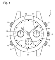
- the terms 3 hours, 6 hours, 9 hours, 12 hours, up, down, upper and lower are used with reference to a chronograph watch seen from above, that is to say seen from the dial side as in the figure 1 .
- the chronograph watch 1 makes it possible to display the current time using an hour hand 10, a minute hand 11 and a small second hand 13 arranged at 3 o'clock. Conventionally, it also comprises a winding crown and time setting 3. To ensure the chronograph function, the watch also includes a chronograph mechanism that can be turned on manually and intended to measure the time elapsed since its start up. In this Indeed, the watch 1 usually comprises a first push button 5 placed at 2 o'clock and controlling the start and stop of the chronograph, and a second push button 7 placed at 4 o'clock and controlling the reset of the chronograph.
- the chronograph watch of the figure 1 further comprises a manually operated switching mechanism for selectively displaying by the same indicator member either a first magnitude or a second magnitude.
- the first magnitude is the elapsed time measured by the chronograph mechanism
- the second magnitude is the current time of a second time zone. It is the hand 21 of the hour meter 20 which constitutes the indicator organ intended to display the first and the second magnitude.
- the watch 1 comprises two additional pushbuttons 23, 25.
- a first of these additional pushbuttons 23, placed at 8 o'clock fulfills the manual control function for the switching mechanism according to the invention.
- the function of the second additional pushbutton 25, placed at 10 o'clock will be explained later.
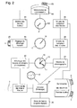
- the chronograph watch 1 comprises a time base 30 associated with a frequency divider 32 for controlling the running of a display of the current time.
- the hands 10, 11 and 13 ensuring the display of the current time are also shown schematically on the figure 2 .
- the time base 30 may of course be in the form of a balance spring, and the frequency divider 32 may be constituted by the work train driving this balance.
- the chronograph watch shown is also equipped with a mechanism of the traditional type scheduled to cooperate with a timer train 42 so as to change the display hours 10 and minutes 11.
- the winding crown and setting time 3 controlling the setting mechanism at the time is also schematically represented in the figure 2 .
- a chronograph mobile 34 which carries the second hand 15, a minute counter mobile 36 which carries the minute counter needle 18, and a clock counter mobile 38 intended to drive the counter needle 21; 20 hours via the switching mechanism 40 according to the invention.
- This switching mechanism the operation of which will be described in detail later, is intended to be actuated manually by means of the push-button 23.
- the switching mechanism 40 the elements which have just been described are components standard of a chronograph mechanism.
- the figure 2 is still schematically the first push button 5 provided to control the running and stopping of the chronograph mechanism, and the second push button 7 provided to control its reset.
- FIG 2 still shows a mobile time "spindle" 44 which is provided to be alternately coupled with / decoupled from the hand 21 of the hour counter 20 by the switching mechanism 40.
- the mobile hours 44 is itself driven by the timer 42 via a time shift adjusting mechanism 46 controlled by the pushbutton 25.
- the chronograph hour counter which is provided to display alternately one or the other of two indications.
- the hour meter hand 21 which constitutes the indicator member of the display device of the present invention.
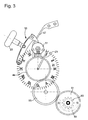
- the figure 6 shows in detail an embodiment of the rotary shaft 73 and the moving mobile, or selector 71, which are in the center of the switching mechanism of the invention.
- the rotary shaft 73 of the switching mechanism is a vertically oriented axis (perpendicular to the plane of the watch) at one end of which is mounted directly the counter needle.
- the rotary shaft 73 has a long square 75 on which the selector 71, whose hole is also square, has the possibility of sliding between a first and a second extreme axial position.
- the cooperation of the two squares, that of the rotary shaft and that of the selector makes it possible to make these two elements integral in rotation with one another.
- the figures 4 , 5 and 6 shows the selector 71 in the first axial position, that is to say in the lower position, pressed against the wheel, or mobile, hour meter 38.
- the selector is coupled to the hour counter wheel , and the latter can therefore drive the selector in rotation.
- the hour counter hand 21 is connected to the hour counter wheel 38 so as to indicate the elapsed hours measured by the chronograph mechanism.
- the switching mechanism of the invention also includes first and second means for synchronizing and stalling the phase to synchronize the rotary shaft with the mobile that drives it. Only the second means of synchronization and timing of the phase, which are provided to adjust the angular position of the shaft 73 to that of the hour wheel 44, are visible on the figure 6 .
- These synchronization means comprise a bell cam 81 formed in the upper face of the selector 71 and a cam follower, or index 83, integral with the "spindle" hours wheel 44. When the selector 71 is pressed against the wheel 44, the index 83 presses against the incline of the cam 81, which has the effect of rotating the latter by driving the selector 71 and the rotary shaft 73.
- the index 83 rotates the cam 81 by sliding on the slope of the latter until it is at the bottom, at the lowest point, called the tick of the cam. Once the index finger 83 seated in the check mark of the cam, the hour wheel "spindle" 44 and the selector 71 are synchronized.
- This column wheel 51 comprises a peripheral sawtooth drive gear on which an operating lever 53 actuated by a pushbutton 23 operates.
- the column wheel 51 is held in a determined position by a jumper (no represent).
- the column wheel further comprises on its underside a series of columns 57a, 57b formed by singing teeth separated from each other by recesses.
- the hollows have a flat bottom and that the edge teeth are truncated so as to also include a flat.
- the edge toothing 57 has half fewer columns (or teeth) than the peripheral toothing, so that driving a step by actuation of the pusher 23 successively brings the bottom of a hollow and the flat of a tooth. in front of a given reference position.
- the switching control is constituted by a flip-flop 61 forked.
- Flip-flop 61 is held by a horizontal axis 63 around which it is free to pivot in a vertical plane.
- a first arm 65 of the rocker (corresponding to the handle of the fork) has at its end a nose 66 biased against the toothing of edge 57 by a return spring 67.
- the second arm of the rocker is shaped to communicate its movement to the selector 71.
- the second arm ends with a fork between the branches 69a, 69b of which the selector is retained.
- two coaxial cylindrical nipples are respectively formed on the inner faces of the two parallel branches 69a, 69b of the fork (only one of these nipples referenced 77 being visible on the figure 6 ).
- the two pins are provided to engage on both sides in the annular notch 79 of the selector 71, so as to drive the latter to slide between the first and second axial position.
- the figures 3 , 4 and 5 still show the kinematic chain which allows the barrel wheel 87 carrying the hour hand 10 to also drive the hour wheel "spindle" 44.
- This kinematic chain comprises a spindle mobile formed of a toothed wheel 91 and a star with 12 branches 93, which is mounted crazy on the barrel of the hour hand.
- the toothed wheel 91 and the barrel wheel are coaxial and the star 93 is mounted to rotate facing the barrel wheel 87.
- the latter carries on its board a jumper 89 which is biased against the star 93 so as to maintain the latter in a given angular position relative to the hour wheel 87.
- the jumper 89 can immobilize it in 12 different positions corresponding to the 12 possible values of the time difference between two time zones.
- the spindle and its gear wheel 91 are driven by the barrel wheel 87 at the speed of one revolution per 12 hours.
- the toothed wheel 91 is arranged to drive the spindle hours wheel 44 via a gear 95.
- the wheel 44 and the wheel 91 having the same number of teeth, they turn to the same wheel. speed corresponding to one turn in 12 hours.
- the time difference between the hour hand 10 and the "spindle" hour wheel 44 is determined by the cooperation of the jumper 89 with the 12-pointed star 93. It is possible to adjust the time difference to using pusher 25 ( figures 1 and 2 ).
- the rotating shaft does not need to be mounted vertically, and can very well rotate horizontally in the plane of the watch much like a time-setting rod. Under these conditions, if the mobile flip is controlled by a flip-flop, it can also move in the horizontal plane in the manner of a time-setting flip-flop. It will be further understood that with such an embodiment, the display member can not be mounted directly on the rotating shaft, but must be driven via a gear train.
- each of the means of synchronization and timing of the phase could for example include at least one magnet and a ferromagnetic element (or preferably two magnets, at least), one being secured to the moving mobile and the other integral with the meter mobile. Under these conditions, the timing of the phase would be ensured by the magnetic forces appearing between the magnet and the ferromagnetic element (or between the two magnets) when they are brought closer to one another.
- the moving mobile could function as a double clutch without synchronization.
- the means of synchronization and calibration of the phase could be constituted by two cores and at least one differential gear as in the document CH 693'155 .
- the means for synchronizing and setting the phase effectively comprise a bell-shaped cam designed to cooperate with a cam follower, it could be, in an equivalent manner, the sliding mobile carrying the follower of the cam. cam and the counter mobile which carries the cam bell.
Landscapes
- Physics & Mathematics (AREA)
- General Physics & Mathematics (AREA)
- Measurement Of Unknown Time Intervals (AREA)
- Electric Clocks (AREA)
- Electromechanical Clocks (AREA)
- Measurement Of Distances Traversed On The Ground (AREA)
Claims (9)
- Anzeigevorrichtung für Zeitmessgeräte, umfassend ein drehendes analoges Anzeigeorgan (21), einen Drehteil (38) eines ersten Zählers und einen Drehteil (44) eines zweiten Zählers, deren Positionen für zwei durch das Anzeigeorgan (21) anzuzeigende Grössen repräsentativ sind, und einen Umschaltmechanismus (40) mit manueller Steuerung (23), der derart vorgesehen ist, dass er selektiv die erste oder die zweite Grösse durch das Anzeigeorgan anzeigt, dadurch gekennzeichnet, dass der Umschaltmechanismus eine kinematisch mit dem Anzeigeorgan (21) verbundene drehbare Welle (73) und einen gleitenden Drehteil (71) umfasst, der drehstarr mit der Welle verbunden ist und derart vorgesehen ist, dass er unter der Einwirkung der manuellen Steuerung (23) gleitet, um auf der Welle (73) selektiv eine erste axiale Position, in der der gleitende Drehteil (71) mit dem Drehteil (38) des ersten Zählers gekuppelt ist, und eine zweite axiale Position, in der der gleitende Drehteil (71) mit dem Drehteil (44) des zweiten Zählers gekuppelt ist, einzunehmen, und dass der Umschaltmechanismus zudem erste Mittel für die Synchronisierung und Einstellung der Phase umfasst, um die Winkelposition der drehbaren Welle (73) derjenigen des Drehteils (38) des ersten Zählers anzupassen, wenn der gleitende Drehteil die erste axiale Position einnimmt, und dass er noch zweite Mittel (81, 83) für die Synchronisierung und Einstellung der Phase umfasst, um die Winkelposition der drehbaren Welle (73) der Position des Drehteils (44) des zweiten Zählers anzupassen, wenn der gleitende Drehteil die zweite axiale Position einnimmt.
- Anzeigevorrichtung nach Anspruch 1, dadurch gekennzeichnet, dass wenigstens eine der beiden durch das Anzeigeorgan (21) anzuzeigenden Grössen eine vergangene Zeit ist.
- Anzeigevorrichtung nach Anspruch 1 oder 2, dadurch gekennzeichnet, dass der Drehteil (38) des ersten Zählers und der Drehteil (44) des zweiten Zählers fliegend auf der drehbaren Welle (73) beiderseits des gleitenden Drehteils (71) montiert sind.
- Anzeigevorrichtung nach Anspruch 3, dadurch gekennzeichnet, dass die drehbare Welle (73) senkrecht angeordnet ist.
- Anzeigevorrichtung nach Anspruch 4, dadurch gekennzeichnet, dass das Anzeigeorgan (21) an der drehbaren Welle (73) befestigt ist.
- Anzeigevorrichtung nach einem der Ansprüche 1 bis 4, dadurch gekennzeichnet, dass das Anzeigeorgan (21) über ein Räderwerk von der drehbaren Welle (73) angetrieben wird.
- Anzeigevorrichtung nach einem der vorhergehenden Ansprüche, dadurch gekennzeichnet, dass die ersten Mittel für die Synchronisierung und Einstellung der Phase eine erste Glockenkurvenscheibe und einen ersten Kurvenscheibenverfolger umfassen, die derart vorgesehen sind, dass sie zusammenwirken, wenn der gleitende Drehteil die erste axiale Position einnimmt, wobei die erste Glockenkurvenscheibe und der erste Kurvenscheibenverfolger vom gleitenden Drehteil (71) bzw. vom Drehteil (38) des ersten Zählers getragen werden.
- Anzeigevorrichtung nach einem der vorhergehenden Ansprüche, dadurch gekennzeichnet, dass die zweiten Mittel (81, 83) für die Synchronisierung und Einstellung der Phase eine zweite Glockenkurvenscheibe (81) und einen zweiten Kurvenscheibenverfolger (83) umfassen, die derart vorgesehen sind, dass sie zusammenwirken, wenn der gleitende Drehteil (71) die zweite axiale Position einnimmt, wobei die zweite Glockenkurvenscheibe (81) und der zweite Kurvenscheibenverfolger (83) vom gleitenden Drehteil (71) bzw. vom Drehteil (44) des zweiten Zählers getragen werden.
- Chronographen-Uhr, dadurch gekennzeichnet, dass sie einen Anzeigemechanismus gemäss einem der vorhergehenden Ansprüche umfasst.
Priority Applications (6)
| Application Number | Priority Date | Filing Date | Title |
|---|---|---|---|
| DE602008004125T DE602008004125D1 (de) | 2008-06-17 | 2008-06-17 | Anzeigevorrichtung zum Anzeigen der einen oder anderen von zwei verschiedenen Angaben mit demselben Anzeigeelement einer Uhr |
| EP08158405A EP2136271B1 (de) | 2008-06-17 | 2008-06-17 | Anzeigevorrichtung zum Anzeigen der einen oder anderen von zwei verschiedenen Angaben mit demselben Anzeigeelement einer Uhr |
| AT08158405T ATE492837T1 (de) | 2008-06-17 | 2008-06-17 | Anzeigevorrichtung zum anzeigen der einen oder anderen von zwei verschiedenen angaben mit demselben anzeigeelement einer uhr |
| US12/485,413 US8179744B2 (en) | 2008-06-17 | 2009-06-16 | Display device for displaying one or other of two different indications with the same timepiece indicator member |
| CN2009101496516A CN101609301B (zh) | 2008-06-17 | 2009-06-17 | 用同一时钟指示器构件显示两个不同读数之一的显示器件 |
| JP2009144016A JP5322796B2 (ja) | 2008-06-17 | 2009-06-17 | 同一時計インジケータ部材で2つの異なる指示のうちの一方または他方を表示するための表示デバイス |
Applications Claiming Priority (1)
| Application Number | Priority Date | Filing Date | Title |
|---|---|---|---|
| EP08158405A EP2136271B1 (de) | 2008-06-17 | 2008-06-17 | Anzeigevorrichtung zum Anzeigen der einen oder anderen von zwei verschiedenen Angaben mit demselben Anzeigeelement einer Uhr |
Publications (2)
| Publication Number | Publication Date |
|---|---|
| EP2136271A1 EP2136271A1 (de) | 2009-12-23 |
| EP2136271B1 true EP2136271B1 (de) | 2010-12-22 |
Family
ID=40303482
Family Applications (1)
| Application Number | Title | Priority Date | Filing Date |
|---|---|---|---|
| EP08158405A Active EP2136271B1 (de) | 2008-06-17 | 2008-06-17 | Anzeigevorrichtung zum Anzeigen der einen oder anderen von zwei verschiedenen Angaben mit demselben Anzeigeelement einer Uhr |
Country Status (6)
| Country | Link |
|---|---|
| US (1) | US8179744B2 (de) |
| EP (1) | EP2136271B1 (de) |
| JP (1) | JP5322796B2 (de) |
| CN (1) | CN101609301B (de) |
| AT (1) | ATE492837T1 (de) |
| DE (1) | DE602008004125D1 (de) |
Cited By (1)
| Publication number | Priority date | Publication date | Assignee | Title |
|---|---|---|---|---|
| EP4270115B1 (de) * | 2022-04-29 | 2024-11-27 | Glashütter Uhrenbetrieb GmbH | Umschaltbarer anzeigemechanismus für uhr |
Families Citing this family (20)
| Publication number | Priority date | Publication date | Assignee | Title |
|---|---|---|---|---|
| EP2362276B1 (de) | 2010-02-25 | 2012-10-31 | Montres Breguet SA | Programmierbares und umprogrammierbares mechanisches Speicherrad für Uhr |
| EP2362277B1 (de) | 2010-02-25 | 2012-10-31 | Montres Breguet SA | Zeitzone auf Wunsch auf den Hauptzeigern einer Uhr |
| CH703261B1 (fr) * | 2010-06-08 | 2014-11-28 | Bulgari Horlogerie S A | Pièce d'horlogerie munie d'une aiguille d'indication horaire mobile entre deux positions. |
| EP2410388B1 (de) * | 2010-07-21 | 2018-04-18 | Blancpain S.A. | Uhr mit Doppelanzeige |
| USD695637S1 (en) * | 2012-02-24 | 2013-12-17 | Compagnie Des Montres Longines, Francillon S.A. (Longines Watch Co., Francillon Ltd.) | Watch |
| USD680883S1 (en) * | 2012-03-06 | 2013-04-30 | Graham SA | Wristwatch |
| CH707233A1 (de) * | 2012-11-22 | 2014-05-30 | Eterna Ag Uhrenfabrik | Minutzenzähler einer Uhr, insbesondere eines Chronographen. |
| USD705088S1 (en) * | 2013-04-10 | 2014-05-20 | Rj Watches S.A. | Watch |
| JP6564561B2 (ja) | 2013-05-31 | 2019-08-21 | ロレックス・ソシエテ・アノニムRolex Sa | 時間情報を記憶及び表示するための時計機構 |
| JP6567806B2 (ja) * | 2013-05-31 | 2019-08-28 | ロレックス・ソシエテ・アノニムRolex Sa | 時間情報を記憶及び表示するための時計機構 |
| USD710735S1 (en) * | 2013-06-17 | 2014-08-12 | Omega Ltd. | Dial |
| USD752468S1 (en) * | 2014-06-18 | 2016-03-29 | Breitling Ag | Dial |
| USD786727S1 (en) * | 2015-09-24 | 2017-05-16 | Bramwell Brown Limited | Tidal clock |
| USD786729S1 (en) * | 2015-09-25 | 2017-05-16 | Bramwell Brown Limited | Tidal clock |
| EP3264199A1 (de) * | 2016-07-01 | 2018-01-03 | Montres Breguet S.A. | Uhr mit schaltvorrichtung für einen uhrmechanismus |
| CN112639629B (zh) * | 2018-08-28 | 2022-11-29 | 百达翡丽日内瓦公司 | 用于钟表的显示装置以及包括该装置的钟表 |
| CH717249A1 (fr) * | 2020-03-20 | 2021-09-30 | Cartier Int Ag | Système de démarrage et d'arrêt d'une fonction et montre comportant un tel système. |
| EP4053639B1 (de) * | 2021-03-04 | 2025-01-01 | Rolex Sa | Vorrichtung zur auswahl von uhrfunktionen |
| EP4270116B1 (de) * | 2022-04-29 | 2025-02-12 | Glashütter Uhrenbetrieb GmbH | Umschaltbarer anzeigemechanismus für uhr |
| DE102023107565B3 (de) | 2023-03-24 | 2024-08-01 | Lange Uhren Gmbh | Kupplungseinrichtung einer Uhr |
Family Cites Families (9)
| Publication number | Priority date | Publication date | Assignee | Title |
|---|---|---|---|---|
| US4021046A (en) * | 1975-02-10 | 1977-05-03 | Marvin Glass & Associates | Accumulative comparative timing device |
| JPS5474570U (de) * | 1977-11-04 | 1979-05-26 | ||
| CH693155A5 (de) | 1998-11-04 | 2003-03-14 | Andreas Strehler | Anzeigemechanik einer Uhr. |
| ATE316663T1 (de) * | 2002-10-07 | 2006-02-15 | Vaucher Mft Fleurier Sa | Chronographenuhrwerk |
| WO2007020289A2 (fr) * | 2005-08-17 | 2007-02-22 | Richemont International S.A. | Mouvement horloger comprenant un indicateur d'unites et un indicateur de dizaines |
| EP2005676A1 (de) | 2006-03-27 | 2008-12-24 | Teamon Systems, Inc. | Drahtloses email-kommunikationssystem zur bereitstellung von teilnehmerkontoaktualisierungsmerkmalen und diesbezügliche verfahren |
| DE602007007070D1 (de) * | 2006-04-07 | 2010-07-22 | Piguet Frederic Sa | |
| EP1933210B1 (de) * | 2006-12-13 | 2010-03-10 | Compagnie des Montres Longines, Francillon SA | Mechanismus für die Zeigerstellung eines Stundenanzeigers |
| ATE466316T1 (de) * | 2007-02-14 | 2010-05-15 | Maurice Lacroix Sa | Mechanismus zur umschaltbaren übertragung |
-
2008
- 2008-06-17 EP EP08158405A patent/EP2136271B1/de active Active
- 2008-06-17 AT AT08158405T patent/ATE492837T1/de not_active IP Right Cessation
- 2008-06-17 DE DE602008004125T patent/DE602008004125D1/de active Active
-
2009
- 2009-06-16 US US12/485,413 patent/US8179744B2/en active Active
- 2009-06-17 CN CN2009101496516A patent/CN101609301B/zh active Active
- 2009-06-17 JP JP2009144016A patent/JP5322796B2/ja active Active
Cited By (2)
| Publication number | Priority date | Publication date | Assignee | Title |
|---|---|---|---|---|
| EP4270115B1 (de) * | 2022-04-29 | 2024-11-27 | Glashütter Uhrenbetrieb GmbH | Umschaltbarer anzeigemechanismus für uhr |
| US12449769B2 (en) | 2022-04-29 | 2025-10-21 | Glashütter Uhrenbetrieb GmbH | Horological switchable display mechanism |
Also Published As
| Publication number | Publication date |
|---|---|
| JP2009300447A (ja) | 2009-12-24 |
| CN101609301A (zh) | 2009-12-23 |
| EP2136271A1 (de) | 2009-12-23 |
| CN101609301B (zh) | 2013-03-27 |
| DE602008004125D1 (de) | 2011-02-03 |
| US20090310445A1 (en) | 2009-12-17 |
| JP5322796B2 (ja) | 2013-10-23 |
| US8179744B2 (en) | 2012-05-15 |
| ATE492837T1 (de) | 2011-01-15 |
Similar Documents
| Publication | Publication Date | Title |
|---|---|---|
| EP2136271B1 (de) | Anzeigevorrichtung zum Anzeigen der einen oder anderen von zwei verschiedenen Angaben mit demselben Anzeigeelement einer Uhr | |
| EP0537617B1 (de) | Uhr mit einem auf einer Motoreinheit eingesetzten Modul | |
| EP1373991B1 (de) | Chronograph mit zwei drehrichtungen | |
| EP2410388B1 (de) | Uhr mit Doppelanzeige | |
| EP0389739B1 (de) | Analoganzeigeeinheit für ein Uhrwerk | |
| EP0772104A1 (de) | Uhr mit Chronographmechanismus | |
| EP2008159B1 (de) | Uhr mit einem zwei-zeitzonen-mechanismus | |
| CH706021B1 (fr) | Mouvement horloger du type chronographe à rattrapante et pièce d'horlogerie munie d'un tel mouvement. | |
| EP2561410B1 (de) | Chronografiemechanismus, uhrwerk und uhr mit diesem mechanismus | |
| EP3264200B1 (de) | Uhr mit schaltvorrichtung für einen uhrmechanismus | |
| EP1178373A1 (de) | Uhr | |
| EP2281222B1 (de) | Anzeigevorrichtung | |
| EP1978424B1 (de) | Chronograph | |
| EP1873696B1 (de) | Mechanischer Golf Zähler | |
| EP1321831B1 (de) | Uhr mit springenden Stunden und Mechanismus zum schnellen Wechsel von Zeitzonen | |
| EP2802945A1 (de) | Uhrwerkbewegungsanzeigemechanismus, der in abhängigkeit von einer informationsanfrage funktioniert | |
| CH719538A1 (fr) | Mouvement d'horlogerie comportant un dispositif d'affichage d'au moins deux fuseaux horaires. | |
| EP2133760A2 (de) | Uhr mit Doppelzeiger | |
| EP2477080B1 (de) | Uhr mit Zeitzonenanzeige entsprechend einer ausgewählten Uhrzeit | |
| EP1960843B1 (de) | Uhrwerk | |
| WO2021171233A1 (fr) | Piece d'horlogerie | |
| FR3107774A1 (fr) | Pièce d’horlogerie | |
| EP3495898A1 (de) | Mechanismus für uhrwerk eines chronographs | |
| CH712642A2 (fr) | Pièce d'horlogerie comprenant un dispositif de commutation d'un mécanisme horloger. | |
| EP1366471A1 (de) | Mechanische uhr mit anzeige der wöchentlichen zyklen |
Legal Events
| Date | Code | Title | Description |
|---|---|---|---|
| PUAI | Public reference made under article 153(3) epc to a published international application that has entered the european phase |
Free format text: ORIGINAL CODE: 0009012 |
|
| AK | Designated contracting states |
Kind code of ref document: A1 Designated state(s): AT BE BG CH CY CZ DE DK EE ES FI FR GB GR HR HU IE IS IT LI LT LU LV MC MT NL NO PL PT RO SE SI SK TR |
|
| AX | Request for extension of the european patent |
Extension state: AL BA MK RS |
|
| GRAP | Despatch of communication of intention to grant a patent |
Free format text: ORIGINAL CODE: EPIDOSNIGR1 |
|
| 17P | Request for examination filed |
Effective date: 20100623 |
|
| AKX | Designation fees paid |
Designated state(s): AT BE BG CH CY CZ DE DK EE ES FI FR GB GR HR HU IE IS IT LI LT LU LV MC MT NL NO PL PT RO SE SI SK TR |
|
| GRAS | Grant fee paid |
Free format text: ORIGINAL CODE: EPIDOSNIGR3 |
|
| GRAA | (expected) grant |
Free format text: ORIGINAL CODE: 0009210 |
|
| AK | Designated contracting states |
Kind code of ref document: B1 Designated state(s): AT BE BG CH CY CZ DE DK EE ES FI FR GB GR HR HU IE IS IT LI LT LU LV MC MT NL NO PL PT RO SE SI SK TR |
|
| REG | Reference to a national code |
Ref country code: GB Ref legal event code: FG4D Free format text: NOT ENGLISH |
|
| REG | Reference to a national code |
Ref country code: CH Ref legal event code: EP |
|
| REG | Reference to a national code |
Ref country code: IE Ref legal event code: FG4D |
|
| REF | Corresponds to: |
Ref document number: 602008004125 Country of ref document: DE Date of ref document: 20110203 Kind code of ref document: P |
|
| REG | Reference to a national code |
Ref country code: DE Ref legal event code: R096 Ref document number: 602008004125 Country of ref document: DE Effective date: 20110203 |
|
| REG | Reference to a national code |
Ref country code: CH Ref legal event code: NV Representative=s name: ICB INGENIEURS CONSEILS EN BREVETS SA |
|
| REG | Reference to a national code |
Ref country code: NL Ref legal event code: VDEP Effective date: 20101222 |
|
| PG25 | Lapsed in a contracting state [announced via postgrant information from national office to epo] |
Ref country code: LT Free format text: LAPSE BECAUSE OF FAILURE TO SUBMIT A TRANSLATION OF THE DESCRIPTION OR TO PAY THE FEE WITHIN THE PRESCRIBED TIME-LIMIT Effective date: 20101222 |
|
| LTIE | Lt: invalidation of european patent or patent extension |
Effective date: 20101222 |
|
| PG25 | Lapsed in a contracting state [announced via postgrant information from national office to epo] |
Ref country code: LV Free format text: LAPSE BECAUSE OF FAILURE TO SUBMIT A TRANSLATION OF THE DESCRIPTION OR TO PAY THE FEE WITHIN THE PRESCRIBED TIME-LIMIT Effective date: 20101222 Ref country code: CY Free format text: LAPSE BECAUSE OF FAILURE TO SUBMIT A TRANSLATION OF THE DESCRIPTION OR TO PAY THE FEE WITHIN THE PRESCRIBED TIME-LIMIT Effective date: 20101222 Ref country code: SE Free format text: LAPSE BECAUSE OF FAILURE TO SUBMIT A TRANSLATION OF THE DESCRIPTION OR TO PAY THE FEE WITHIN THE PRESCRIBED TIME-LIMIT Effective date: 20101222 Ref country code: HR Free format text: LAPSE BECAUSE OF FAILURE TO SUBMIT A TRANSLATION OF THE DESCRIPTION OR TO PAY THE FEE WITHIN THE PRESCRIBED TIME-LIMIT Effective date: 20101222 Ref country code: BG Free format text: LAPSE BECAUSE OF FAILURE TO SUBMIT A TRANSLATION OF THE DESCRIPTION OR TO PAY THE FEE WITHIN THE PRESCRIBED TIME-LIMIT Effective date: 20110322 Ref country code: SI Free format text: LAPSE BECAUSE OF FAILURE TO SUBMIT A TRANSLATION OF THE DESCRIPTION OR TO PAY THE FEE WITHIN THE PRESCRIBED TIME-LIMIT Effective date: 20101222 Ref country code: FI Free format text: LAPSE BECAUSE OF FAILURE TO SUBMIT A TRANSLATION OF THE DESCRIPTION OR TO PAY THE FEE WITHIN THE PRESCRIBED TIME-LIMIT Effective date: 20101222 Ref country code: AT Free format text: LAPSE BECAUSE OF FAILURE TO SUBMIT A TRANSLATION OF THE DESCRIPTION OR TO PAY THE FEE WITHIN THE PRESCRIBED TIME-LIMIT Effective date: 20101222 |
|
| REG | Reference to a national code |
Ref country code: IE Ref legal event code: FD4D |
|
| PG25 | Lapsed in a contracting state [announced via postgrant information from national office to epo] |
Ref country code: CZ Free format text: LAPSE BECAUSE OF FAILURE TO SUBMIT A TRANSLATION OF THE DESCRIPTION OR TO PAY THE FEE WITHIN THE PRESCRIBED TIME-LIMIT Effective date: 20101222 Ref country code: EE Free format text: LAPSE BECAUSE OF FAILURE TO SUBMIT A TRANSLATION OF THE DESCRIPTION OR TO PAY THE FEE WITHIN THE PRESCRIBED TIME-LIMIT Effective date: 20101222 Ref country code: ES Free format text: LAPSE BECAUSE OF FAILURE TO SUBMIT A TRANSLATION OF THE DESCRIPTION OR TO PAY THE FEE WITHIN THE PRESCRIBED TIME-LIMIT Effective date: 20110402 Ref country code: NO Free format text: LAPSE BECAUSE OF FAILURE TO SUBMIT A TRANSLATION OF THE DESCRIPTION OR TO PAY THE FEE WITHIN THE PRESCRIBED TIME-LIMIT Effective date: 20110322 Ref country code: PT Free format text: LAPSE BECAUSE OF FAILURE TO SUBMIT A TRANSLATION OF THE DESCRIPTION OR TO PAY THE FEE WITHIN THE PRESCRIBED TIME-LIMIT Effective date: 20110422 Ref country code: IS Free format text: LAPSE BECAUSE OF FAILURE TO SUBMIT A TRANSLATION OF THE DESCRIPTION OR TO PAY THE FEE WITHIN THE PRESCRIBED TIME-LIMIT Effective date: 20110422 Ref country code: GR Free format text: LAPSE BECAUSE OF FAILURE TO SUBMIT A TRANSLATION OF THE DESCRIPTION OR TO PAY THE FEE WITHIN THE PRESCRIBED TIME-LIMIT Effective date: 20110323 |
|
| PG25 | Lapsed in a contracting state [announced via postgrant information from national office to epo] |
Ref country code: SK Free format text: LAPSE BECAUSE OF FAILURE TO SUBMIT A TRANSLATION OF THE DESCRIPTION OR TO PAY THE FEE WITHIN THE PRESCRIBED TIME-LIMIT Effective date: 20101222 Ref country code: PL Free format text: LAPSE BECAUSE OF FAILURE TO SUBMIT A TRANSLATION OF THE DESCRIPTION OR TO PAY THE FEE WITHIN THE PRESCRIBED TIME-LIMIT Effective date: 20101222 Ref country code: NL Free format text: LAPSE BECAUSE OF FAILURE TO SUBMIT A TRANSLATION OF THE DESCRIPTION OR TO PAY THE FEE WITHIN THE PRESCRIBED TIME-LIMIT Effective date: 20101222 Ref country code: RO Free format text: LAPSE BECAUSE OF FAILURE TO SUBMIT A TRANSLATION OF THE DESCRIPTION OR TO PAY THE FEE WITHIN THE PRESCRIBED TIME-LIMIT Effective date: 20101222 |
|
| PLBE | No opposition filed within time limit |
Free format text: ORIGINAL CODE: 0009261 |
|
| STAA | Information on the status of an ep patent application or granted ep patent |
Free format text: STATUS: NO OPPOSITION FILED WITHIN TIME LIMIT |
|
| PG25 | Lapsed in a contracting state [announced via postgrant information from national office to epo] |
Ref country code: DK Free format text: LAPSE BECAUSE OF FAILURE TO SUBMIT A TRANSLATION OF THE DESCRIPTION OR TO PAY THE FEE WITHIN THE PRESCRIBED TIME-LIMIT Effective date: 20101222 Ref country code: IE Free format text: LAPSE BECAUSE OF FAILURE TO SUBMIT A TRANSLATION OF THE DESCRIPTION OR TO PAY THE FEE WITHIN THE PRESCRIBED TIME-LIMIT Effective date: 20101222 |
|
| 26N | No opposition filed |
Effective date: 20110923 |
|
| PG25 | Lapsed in a contracting state [announced via postgrant information from national office to epo] |
Ref country code: MT Free format text: LAPSE BECAUSE OF FAILURE TO SUBMIT A TRANSLATION OF THE DESCRIPTION OR TO PAY THE FEE WITHIN THE PRESCRIBED TIME-LIMIT Effective date: 20101222 Ref country code: IT Free format text: LAPSE BECAUSE OF FAILURE TO SUBMIT A TRANSLATION OF THE DESCRIPTION OR TO PAY THE FEE WITHIN THE PRESCRIBED TIME-LIMIT Effective date: 20101222 |
|
| BERE | Be: lapsed |
Owner name: MONTRES BREGUET S.A. Effective date: 20110630 |
|
| REG | Reference to a national code |
Ref country code: DE Ref legal event code: R097 Ref document number: 602008004125 Country of ref document: DE Effective date: 20110923 |
|
| PG25 | Lapsed in a contracting state [announced via postgrant information from national office to epo] |
Ref country code: BE Free format text: LAPSE BECAUSE OF NON-PAYMENT OF DUE FEES Effective date: 20110630 |
|
| PG25 | Lapsed in a contracting state [announced via postgrant information from national office to epo] |
Ref country code: MC Free format text: LAPSE BECAUSE OF NON-PAYMENT OF DUE FEES Effective date: 20110630 |
|
| PG25 | Lapsed in a contracting state [announced via postgrant information from national office to epo] |
Ref country code: LU Free format text: LAPSE BECAUSE OF NON-PAYMENT OF DUE FEES Effective date: 20110617 |
|
| PG25 | Lapsed in a contracting state [announced via postgrant information from national office to epo] |
Ref country code: TR Free format text: LAPSE BECAUSE OF FAILURE TO SUBMIT A TRANSLATION OF THE DESCRIPTION OR TO PAY THE FEE WITHIN THE PRESCRIBED TIME-LIMIT Effective date: 20101222 |
|
| PG25 | Lapsed in a contracting state [announced via postgrant information from national office to epo] |
Ref country code: HU Free format text: LAPSE BECAUSE OF FAILURE TO SUBMIT A TRANSLATION OF THE DESCRIPTION OR TO PAY THE FEE WITHIN THE PRESCRIBED TIME-LIMIT Effective date: 20101222 |
|
| REG | Reference to a national code |
Ref country code: FR Ref legal event code: PLFP Year of fee payment: 9 |
|
| REG | Reference to a national code |
Ref country code: FR Ref legal event code: PLFP Year of fee payment: 10 |
|
| REG | Reference to a national code |
Ref country code: FR Ref legal event code: PLFP Year of fee payment: 11 |
|
| P01 | Opt-out of the competence of the unified patent court (upc) registered |
Effective date: 20230611 |
|
| PGFP | Annual fee paid to national office [announced via postgrant information from national office to epo] |
Ref country code: DE Payment date: 20250520 Year of fee payment: 18 |
|
| PGFP | Annual fee paid to national office [announced via postgrant information from national office to epo] |
Ref country code: GB Payment date: 20250520 Year of fee payment: 18 |
|
| PGFP | Annual fee paid to national office [announced via postgrant information from national office to epo] |
Ref country code: FR Payment date: 20250520 Year of fee payment: 18 |
|
| PGFP | Annual fee paid to national office [announced via postgrant information from national office to epo] |
Ref country code: CH Payment date: 20250701 Year of fee payment: 18 |