EP2136236A1 - Optische verlustvorrichtung - Google Patents
Optische verlustvorrichtung Download PDFInfo
- Publication number
- EP2136236A1 EP2136236A1 EP08777784A EP08777784A EP2136236A1 EP 2136236 A1 EP2136236 A1 EP 2136236A1 EP 08777784 A EP08777784 A EP 08777784A EP 08777784 A EP08777784 A EP 08777784A EP 2136236 A1 EP2136236 A1 EP 2136236A1
- Authority
- EP
- European Patent Office
- Prior art keywords
- optical
- optical fiber
- loop portion
- loss device
- loop
- Prior art date
- Legal status (The legal status is an assumption and is not a legal conclusion. Google has not performed a legal analysis and makes no representation as to the accuracy of the status listed.)
- Withdrawn
Links
- 230000003287 optical effect Effects 0.000 title claims abstract description 100
- 239000013307 optical fiber Substances 0.000 claims abstract description 85
- 238000004804 winding Methods 0.000 claims abstract description 13
- 230000002238 attenuated effect Effects 0.000 claims abstract description 4
- 238000005452 bending Methods 0.000 description 27
- 238000003780 insertion Methods 0.000 description 19
- 230000037431 insertion Effects 0.000 description 19
- 238000005259 measurement Methods 0.000 description 16
- 238000001228 spectrum Methods 0.000 description 14
- 238000000034 method Methods 0.000 description 8
- 238000005253 cladding Methods 0.000 description 7
- 239000011248 coating agent Substances 0.000 description 5
- 238000000576 coating method Methods 0.000 description 5
- 239000000835 fiber Substances 0.000 description 4
- 230000005540 biological transmission Effects 0.000 description 3
- 238000001514 detection method Methods 0.000 description 3
- 229910052736 halogen Inorganic materials 0.000 description 3
- 150000002367 halogens Chemical class 0.000 description 3
- 238000004891 communication Methods 0.000 description 2
- 238000010168 coupling process Methods 0.000 description 2
- 238000005859 coupling reaction Methods 0.000 description 2
- 238000005498 polishing Methods 0.000 description 2
- 239000011347 resin Substances 0.000 description 2
- 229920005989 resin Polymers 0.000 description 2
- 230000002441 reversible effect Effects 0.000 description 2
- 230000000903 blocking effect Effects 0.000 description 1
- 238000006243 chemical reaction Methods 0.000 description 1
- 230000008878 coupling Effects 0.000 description 1
- 239000013078 crystal Substances 0.000 description 1
- 230000000694 effects Effects 0.000 description 1
- 239000002223 garnet Substances 0.000 description 1
- 239000011521 glass Substances 0.000 description 1
- 238000002844 melting Methods 0.000 description 1
- 230000008018 melting Effects 0.000 description 1
- 238000012544 monitoring process Methods 0.000 description 1
- 230000001902 propagating effect Effects 0.000 description 1
- 238000005096 rolling process Methods 0.000 description 1
Images




Classifications
-
- G—PHYSICS
- G02—OPTICS
- G02B—OPTICAL ELEMENTS, SYSTEMS OR APPARATUS
- G02B6/00—Light guides; Structural details of arrangements comprising light guides and other optical elements, e.g. couplings
- G02B6/24—Coupling light guides
- G02B6/26—Optical coupling means
- G02B6/264—Optical coupling means with optical elements between opposed fibre ends which perform a function other than beam splitting
- G02B6/266—Optical coupling means with optical elements between opposed fibre ends which perform a function other than beam splitting the optical element being an attenuator
-
- G—PHYSICS
- G02—OPTICS
- G02B—OPTICAL ELEMENTS, SYSTEMS OR APPARATUS
- G02B6/00—Light guides; Structural details of arrangements comprising light guides and other optical elements, e.g. couplings
- G02B6/24—Coupling light guides
- G02B6/26—Optical coupling means
- G02B6/28—Optical coupling means having data bus means, i.e. plural waveguides interconnected and providing an inherently bidirectional system by mixing and splitting signals
- G02B6/293—Optical coupling means having data bus means, i.e. plural waveguides interconnected and providing an inherently bidirectional system by mixing and splitting signals with wavelength selective means
- G02B6/29331—Optical coupling means having data bus means, i.e. plural waveguides interconnected and providing an inherently bidirectional system by mixing and splitting signals with wavelength selective means operating by evanescent wave coupling
-
- G—PHYSICS
- G02—OPTICS
- G02B—OPTICAL ELEMENTS, SYSTEMS OR APPARATUS
- G02B6/00—Light guides; Structural details of arrangements comprising light guides and other optical elements, e.g. couplings
- G02B6/24—Coupling light guides
- G02B6/26—Optical coupling means
- G02B6/28—Optical coupling means having data bus means, i.e. plural waveguides interconnected and providing an inherently bidirectional system by mixing and splitting signals
- G02B6/293—Optical coupling means having data bus means, i.e. plural waveguides interconnected and providing an inherently bidirectional system by mixing and splitting signals with wavelength selective means
- G02B6/29379—Optical coupling means having data bus means, i.e. plural waveguides interconnected and providing an inherently bidirectional system by mixing and splitting signals with wavelength selective means characterised by the function or use of the complete device
- G02B6/29389—Bandpass filtering, e.g. 1x1 device rejecting or passing certain wavelengths
Definitions
- the present invention relates to an optical attenuator or an optical switch which is used for optical measurement, optical communication or the like.
- a laser light source, an ASE light source or the like may be equipped with an optical attenuator for adjusting light output, or may be equipped with an optical switch for the sake of safety.
- Many of light sources which output lights by optical fibers focus or collect a light generated in a light generating section on an optical fiber, and guide the light to an output optical fiber by using a guiding optical fiber.
- the optical attenuator or the optical switch is provided in an intermediate portion of this guiding optical fiber.
- the optical attenuator there are a method in which an attenuator plate or a knife-edge is inserted into a region of collimated beam to adjust a light transmission rate; and a method in which a coupling efficiency to a collimating light-receiving system is varied by applying an external magnetic field to a garnet crystal having a Faraday effect, while varying a direction of a propagating collimated light by means of prism or mirror (Patent Documents 1 and 2).
- a light path is switched by deviating an optical axis of one of optical fibers facing each other, so as to cause the one to face a different optical fiber.
- an optical port to be coupled is switched by changing a position and/or angle of mirror.
- an optical attenuator or optical switch (hereinafter, referred to as an optical loss device) is inserted between optical fibers; an attenuator plate, a blocking plate and/or a lens for collimating a diffused light outputted from the optical fiber need to be inserted.
- an optical loss device when a reflected light generated at an end surface of the optical fiber, at a surface of the lens or at a surface of the attenuator plate enters a light source section, an output power tends to become unstable and/or a ripple tends to appear on a wavelength spectrum of an output light due to multiple reflection. Thereby, a quality of light source might be greatly degraded.
- the reflected light enters into an excited laser medium so that a giant pulse is generated.
- this giant pulse damages a resonator mirror constituting the laser and/or damages an output end surface of the optical fiber. Therefore, it is necessary that the reflection is reduced illimitably.
- an end surface of the optical fiber is arranged obliquely, or that an AR coat is applied to a reflecting surface. However, this induces a high-cost structure, and moreover, it is difficult to fully suppress the reflection.
- an optical loss device capable of producing a loss inside the optical fiber without bringing light to a space. That is, an all fiber type optical loss device is needed.
- the all fiber type optical loss device a method is known in which the loss is obtained by winding the optical fiber around a circular cylinder (Patent Documents 5 and 6), and a method is known in which an attenuation is obtained by applying a one-dimensionally expanding and contracting operation to the optical fiber wound in a circular loop so that the optical fiber is deformed in an oval loop (Patent Document 7).
- the all fiber type optical loss device in a case that the loss is obtained by winding the optical fiber around the circular cylinder as mentioned above; it is necessary to set a small diameter of the circular cylinder which is provided for rolling up the optical fiber, and/or to increase a winding number, in order to obtain great optical loss. In the case that the winding number is increased, there is a risk that the optical fiber is entangled.
- FIG. 1 is a schematic view in the case that the attenuation is obtained by applying the one-dimensionally expanding and contracting operation to the optical fiber 1 wound in a circular loop so that the optical fiber is deformed in an oval loop as mentioned above.
- FIG. 1 schematically shows loop shapes of the optical fiber before the one-dimensionally expanding and contracting operation (a), and at the time of the one-dimensionally expanding and contracting operation (b).
- the oval loop portion includes a portion having a small bending radius and also includes a portion having a large bending radius, as compared with the shape before the expanding and contracting operation (a). That is, in the portion having the large bending radius, a bending loss is reduced and hence is not efficient.
- FIG. 2 shows a schematic view of a means according to the present invention.
- FIG. 2 schematically shows loop shapes before (a) and after (b) a loop portion of the optical fiber 1 is twisted.
- Inventers of the present application have found that the bending radius in all areas of the loop portion of optical fiber after (b) the loop portion has been twisted is smaller than that before (a) the loop portion is twisted. According to this find, the present invention has been created.
- an optical loss device including an optical fiber, characterized in that the optical loss device comprises: a loop portion formed by winding the optical fiber in a loop shape at least one turn; and two rotation centers which are located in a plane defined by the loop portion and which face each other, the two rotation centers forming a rotation axis located in the plane, and that a light of wavelength band is attenuated by twisting the loop portion around the rotation axis to vary a shape of the loop portion.
- the optical loss device including an optical fiber, characterized in that the two rotation centers of the loop portion are respectively used as holding portions; and the loop portion is twisted by rotating the two holding portions around the rotation axis.
- the optical loss device including an optical fiber, characterized in that the optical loss device further comprises two rods through a loop of the loop portion; and the loop portion is twisted by rotating one of the two rods around the rotation axis.
- FIG. 3 is a schematic view showing the concept of twist.
- a reference sign 1 denotes a loop portion formed by optical fiber
- a plane U denotes a plane including (given by) the loop portion.
- reference signs X0 and Y0 denote points of the loop portion which faces each other relative to the loop portion
- a reference sign Z denotes a rotation axis which is included in the plane U and which functions (is formed) by regarding the points X0 and Y0 as rotation centers.
- line segments X1-X2 and Y1-Y2 denote respective tangents to the loop portion at the points X0 and Y0.
- the twist means that the loop portion is rotated about the rotation axis Z so as to cause a rotation angle of the line segment X1-X2 to become different from a rotation angle of the line segment Y1-Y2 relative to the rotation axis Z.
- an optical loss device which has a low insertion loss, which generates substantially no reflection and which causes the optical fiber not to become entangled.
- the present invention can provide a technique applicable not only to an optical measurement and an optical communication but also to the general field of an optical transmission using optical fiber, as an optical attenuator or optical switch.
- the bending loss of optical fiber varies in accordance with the wavelength of light, the refractive indexes of core and cladding, the core diameter, and the like.
- various optical fibers are manufactured in a range from near-ultraviolet wavelength to infrared wavelength. It is necessary to properly select a type, the bending radius and the winding number of optical fiber in order to obtain a most high-efficiency attenuation with a desired wavelength.
- FIG. 4 shows the best mode for carrying out the present invention.
- a part of one optical fiber 1 has been wound n times (n turns) with a diameter value equal to d, and is held at two holding portions 2 and 3.
- the value d of diameter is set at a value which can obtain a desired optical attenuation rate under the desired wavelength ⁇ when the optical fiber is wound 2n times (2n turns) with a diameter value equal to d/2.
- the value of diameter d is set at 26mm which is a value minimum-necessary to avoid an occurrence of the bending loss under the wavelength value equal to 543nm. If the winding number of the optical fiber is lacking, or if the bending radius is too large; there is a possibility that a sufficient bending radius cannot be obtained by the twist.
- FIG. 4 in order to show a rotational direction of the holding portion provided for giving a twist to the loop-shaped optical fiber; a portion of the optical fiber which extends from the holding portion 2 to a left side is indicated by A, a portion of the optical fiber which extends from the holding portion 2 to a right side is indicated by B, a portion of the optical fiber which extends from the holding portion 3 to a left side is indicated by A', and a portion of the optical fiber which extends from the holding portion 3 to a right side is indicated by B'.
- FIG. 6 shows a state where the holding portion 3 has been rotated by 180 degrees around a center axis given by an imaginary straight line O - O' while keeping fixing or locking the holding portion 2.
- This imaginary straight line O - O' passes through the holding portion 2 and the holding portion 3 as shown in FIG. 6 .
- 2n times loops each having a diameter value equal to d/2 are formed.
- the optical fiber wound 2n times to have the diameter equal to d/2 achieves the desired optical attenuation rate under the desired wavelength ⁇ .
- the rotation axis has only to exist in a plane U including the loop portion of optical fiber. That is, it is not necessary that the straight line O - O' passes through the holding portions.
- the loop portion includes a portion which causes its bending radius to become smaller and also includes a portion which causes its bending radius to become larger. That is, the bending loss is reduced in the portion which causes its bending radius to become larger, resulting in inefficiency.
- the loop portion of optical fiber is twisted by the method according to the present invention as shown in FIG. 2 , the bending radius becomes smaller in all areas of the loop portion of optical finer. Therefore, the bending loss can be effectively generated.
- the optical loss device according to the present invention is constituted substantially only by the optical fiber, the reflection is not generated at all. Moreover, the optical loss device according to the present invention has no space-coupling portion, and hence can achieve a low loss.
- a desired optical attenuation rate can be obtained by controlling a rotation angle of the holding portion 3 shown in FIG. 6 .
- the optical loss device according to the present invention serves to be reversible, the optical loss device according to the present invention also functions as a variable optical loss device.
- the optical loss device according to the present invention can be used also by increasing the winding number of optical fiber or by connecting a plurality of optical loss devices according to the present invention with one another in series.
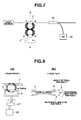
- FIG. 7 shows an example of a means of determining an attenuation amount (degree) of the optical device according to the present invention.
- a light emitted from a light source passes though the optical loss device according to the present invention, and then is made to branch off by a TAP coupler 24. Thereby, a part of the light which has passed through the optical loss device is received by a photodiode 25 so that an intensity of the light is detected.
- the attenuation amount of light intensity from the light source can be checked.
- FIG. 8 shows an embodiment of the optical loss device according to the present invention.
- the optical fiber 1 core diameter: 2.1 ⁇ m, cladding diameter: 125 ⁇ m, UV coating diameter: 250 ⁇ m, NA: 0.13, cutoff wavelength: 350nm
- the optical fiber 1 is wound 10 turns in a circular-loop shape in the condition of ⁇ 26mm.
- Two SUS rods 4 and 5 ⁇ 3mm are inserted through this loop.
- the SUS rod 4 is fastened, and the SUS rod 5 is held by a rotating mechanism 6.
- the rotating mechanism 6 is attached to a reduction gear 27 (speed reduction ratio: 0.25) connected with a rotation shaft of a rotary solenoid 26 (GDAX050 made by Emessem Solenoid Company).
- the SUS rod 5 can be rotated to a predetermined rotational angle by driving the rotary solenoid 26.
- the SUS rod 5 is placed so as to deviate by 5° relative to the SUS rod 4 in order to obtain a state where the loop portion of optical fiber 1 has not yet been twisted.
- the angle of SUS rod 5 relative to the SUS rod 4 in such a placement is defined as a reference angle.
- Loss spectra of the optical fiber 1 were measured by using a measurement system shown by FIG. 9 , when the SUS rod 5 had been rotated by 0 degree (i.e., at the reference angle) and when the SUS rod 5 had been rotated by 180 degrees.
- the measurement system in FIG. 9 includes a halogen light source and an optical spectrum analyzer (AQ6315A made by Ando Electric Co., Ltd.). At first, the halogen light source is turned on, and a light spectrum emitted from the optical loss device is measured, as shown in FIG. 9(a) . Next, the optical loss device is removed from the measurement system, and then a light spectrum is measured, as shown in FIG. 9(b) . By calculating a difference between these light-spectrum data, the optical loss spectrum was measured.
- FIG. 10 shows the optical loss spectra when the SUS rod 5 has been rotated by 0 degree and by 180 degrees.
- the loss within a range between 550nm and 600nm greatly varies in accordance with the rotation of SUS rod 5 from 0 degree to 180 degrees.
- a remarkable variation of the optical attenuation rate can be obtained.
- the insertion loss of optical fiber 1 was measured by using an ASE light source 31 (CFA-43LU made by Central Glass Co., Ltd.) of wavelength 543nm and by using a power meter 32 (MA9411A made by Anritsu Corporation) when the SUS rod 5 was positioned at the reference angle as shown in FIG. 11 .
- a measured value of this insertion loss was equal to 0.08dB.
- values of the insertion loss of optical fiber 1 were measured in the similar manner as the above, when the SUS rod 5 had been rotated and thereby was positioned at 0 degree, 30 degrees, 60 degrees, 90 degrees, 120 degrees, 150 degrees and 180 degrees relative to the reference angle.
- FIG. 12 shows a state of optical fiber when the optical fiber has been rotated up to 180 degrees.
- FIG. 13 shows a relation between the rotation angle of SUS rod 5 and the insertion loss of the twisted optical fiber 1. As shown in FIG. 13 , the insertion loss increases most steeply in the vicinity of 90 degrees in rotation angle. Then, the insertion loss increases moderately when the rotation angle becomes larger than or equal to 120 degrees. The insertion loss at a rotation angle of 180 degrees was equal to 5.40dB.
- the measurement system in FIG. 14 includes the ASE light source 31 (CFA-43LU made by Central Glass Co., Ltd.) of 543nm band, a 3dB-coupler 30 (core diameter: 2.1 ⁇ m, cladding diameter: 125 ⁇ m, UV coating diameter: 250 ⁇ m, NA: 0.13, cutoff wavelength: 350nm, transmission excess loss: 0.2dB) and the power meter 32 (MA9411A made by Anritsu Corporation).
- An end of the 3dB-coupler 30 is connected by melting with the optical loss device according to the present invention. Further, a terminal treatment (8° oblique polishing) is given to an end of this optical loss device in order not to cause reflections. A reflection of the light emitted from the ASE light source 31 of 543nm band is detected by the power meter 32. Thus, the light reflection can be measured.
- the reflection measured by using the measurement system shown in FIG. 14 was equal to -50dB.
- the reflection is attenuated by 50dB relative to outgoing power of the ASE light source, i.e., a minimum limit of detection of reflected light in the measuring method shown by FIG. 14 is equal to -50dB. That is, the reflection of the optical loss device according to the present invention is lower than or equal to the minimum limit of detection.
- a measured insertion loss was equal to 0.08dB.
- an arbitrary value of attenuation rate could be obtained between 0.08dB and 5.2dB. That is, a variable attenuator can be constructed according to the present invention.
- FIG. 15 shows an embodiment of optical loss device according to the present invention.
- the optical fiber 1 core diameter: 2.1 ⁇ m, cladding diameter: 125 ⁇ m, UV coating diameter: 250 ⁇ m, NA: 0.13, cutoff wavelength: 350nm
- the holding portion 3 is formed by fixing the loop portion of optical fiber 1, by means of UV curable resin, to the reduction gear 27 (speed reduction ratio: 0.25) connected with the rotation shaft of rotary solenoid 26 (GDAX050 made by Emessem Solenoid Company).
- the holding portion 2 is formed by fixing (fastening) the loop portion at a side opposite to the holding portion 3 by means of UV curable resin. Therefore, the holding portion 3 of the loop portion is rotated by a drive of the rotary solenoid 26 so that the loop portion is twisted.
- the insertion loss of optical fiber 1 was measured by using the measurement system shown by FIG. 11 in the similar manner as the first embodiment, when the holding portion 3 had been rotated by 180 degrees. As a result, the insertion loss was found to be equal to 5.35dB under a wavelength condition of 543nm. Accordingly, it could be confirmed that the second embodiment functions as the optical loss device in the same manner as the first embodiment.
- FIG. 16 shows an embodiment of optical loss device according to the present invention.
- the optical loss device in this embodiment is constructed by connecting in series four optical loss devices each of which is same as the structure of optical loss device in the first embodiment except that the winding number of optical fiber 1 is set at 25 turns.
- SUS rods 7, 8, 9 and 10 had been fixed, SUS rods 11, 12, 13 and 14 were rotated by 180 degrees from the reference angle.
- the insertion loss of optical fiber 1 was measured by using the measurement system shown by FIG. 11 in the similar manner as the first embodiment. As a result, the insertion loss was equal to 50dB under the wavelength condition of 543nm.
- an optical loss device having an attenuation rate of 50dB between points C and D could be achieved.
- the reflection of the optical loss device shown in FIG. 16 was measured by using the measurement system shown by FIG. 14 in the similar manner as the first embodiment. As a result, the reflection was lower than or equal to the detection minimum limit of -50dB.
- FIG. 17 shows an embodiment of optical loss device according to the present invention.
- ends of three internal light sources 16 (488nm-wavelength light source: Tm-Yb codoped up-conversion fiber light source), 17 (543nm-wavelength light source: CFA-43LU made by Central Glass Co., Ltd.) and 18 (635nm-wavelength light source: FOSS-01-3S-4/125-635-S-1 made by OZ optics) which have wavelengths different from one another are connected respectively with optical loss devices 19, 20 and 21 each of which has the similar structure as that of the third embodiment. Further, another ends of the optical loss devices 19, 20 and 21 are connected with a fiber-fused-taper-type WDM 22 and are collected or integrated into one optical fiber so that light is outputted from an output connector 23.
- the optical loss device of this embodiment can also function as an optical switch for switching between ON and OFF of a specific wavelength(s).
Landscapes
- Physics & Mathematics (AREA)
- General Physics & Mathematics (AREA)
- Optics & Photonics (AREA)
- Mechanical Light Control Or Optical Switches (AREA)
- Optical Couplings Of Light Guides (AREA)
- Light Guides In General And Applications Therefor (AREA)
Applications Claiming Priority (2)
| Application Number | Priority Date | Filing Date | Title |
|---|---|---|---|
| JP2007180876A JP2009020167A (ja) | 2007-07-10 | 2007-07-10 | 光損失デバイス |
| PCT/JP2008/061984 WO2009008304A1 (ja) | 2007-07-10 | 2008-07-02 | 光損失デバイス |
Publications (1)
| Publication Number | Publication Date |
|---|---|
| EP2136236A1 true EP2136236A1 (de) | 2009-12-23 |
Family
ID=40228482
Family Applications (1)
| Application Number | Title | Priority Date | Filing Date |
|---|---|---|---|
| EP08777784A Withdrawn EP2136236A1 (de) | 2007-07-10 | 2008-07-02 | Optische verlustvorrichtung |
Country Status (4)
| Country | Link |
|---|---|
| US (1) | US20100189405A1 (de) |
| EP (1) | EP2136236A1 (de) |
| JP (1) | JP2009020167A (de) |
| WO (1) | WO2009008304A1 (de) |
Family Cites Families (14)
| Publication number | Priority date | Publication date | Assignee | Title |
|---|---|---|---|---|
| JPS6260902U (de) | 1985-10-07 | 1987-04-15 | ||
| US4996420A (en) * | 1989-10-05 | 1991-02-26 | Hughes Aircraft Company | Measurement of optical attenuation along the length of bent optical fibers |
| JPH0426802A (ja) * | 1990-05-22 | 1992-01-30 | Fujitsu Ltd | 光減衰器 |
| JPH07159705A (ja) | 1993-12-08 | 1995-06-23 | Matsushita Electric Ind Co Ltd | 可変光減衰器およびこれを用いた可変光反射器 |
| JP3892072B2 (ja) | 1995-12-05 | 2007-03-14 | 株式会社フジクラ | 光スイッチ |
| US5677977A (en) * | 1996-05-16 | 1997-10-14 | Sentech Systems, Inc. | Optical attenuator |
| US5841915A (en) * | 1996-11-04 | 1998-11-24 | Honeywell Inc. | Apparatus for determining the effect of modal noise on a communication system by affecting an optical fiber discontinuity |
| JP2933919B1 (ja) * | 1998-08-04 | 1999-08-16 | サンテック株式会社 | 光アッテネータ及び光アッテネータモジュール |
| JP2000075222A (ja) * | 1998-08-31 | 2000-03-14 | Tatsuta Electric Wire & Cable Co Ltd | 可変型光ファイバ減衰器 |
| JP3472524B2 (ja) | 1999-03-04 | 2003-12-02 | Fdk株式会社 | 光アッテネータ |
| JP2001228337A (ja) * | 2000-02-18 | 2001-08-24 | Hitachi Ltd | 光減衰器 |
| US7336418B1 (en) * | 2000-03-01 | 2008-02-26 | Fdk Corporation | Optical attenuator |
| JP2005077973A (ja) * | 2003-09-03 | 2005-03-24 | Hitachi Metals Ltd | 可変光減衰器 |
| JP2006078837A (ja) | 2004-09-10 | 2006-03-23 | Omron Corp | 光スイッチ |
-
2007
- 2007-07-10 JP JP2007180876A patent/JP2009020167A/ja active Pending
-
2008
- 2008-07-02 EP EP08777784A patent/EP2136236A1/de not_active Withdrawn
- 2008-07-02 US US12/668,363 patent/US20100189405A1/en not_active Abandoned
- 2008-07-02 WO PCT/JP2008/061984 patent/WO2009008304A1/ja not_active Ceased
Non-Patent Citations (1)
| Title |
|---|
| See references of WO2009008304A1 * |
Also Published As
| Publication number | Publication date |
|---|---|
| WO2009008304A1 (ja) | 2009-01-15 |
| US20100189405A1 (en) | 2010-07-29 |
| JP2009020167A (ja) | 2009-01-29 |
Similar Documents
| Publication | Publication Date | Title |
|---|---|---|
| Harumoto et al. | Gain-flattening filter using long-periodfiber gratings | |
| US6925230B2 (en) | Long period chiral fiber grating apparatus | |
| US7920763B1 (en) | Mode field expanded fiber collimator | |
| EP0733223B1 (de) | Wellenleiterkopplung | |
| US8154715B2 (en) | Method for monitoring and measuring optical properties of device in polarization maintaining fibers by using reference fiber bragg grating and fiber components manufactured thereby | |
| EP1628148A1 (de) | Durch Mikrobiegungen erzeugte polarisationsunempfindliche Fasergitter und Vorrichtungen, die selbige nutzen | |
| CA2215078A1 (en) | Optical coupler | |
| US8891917B2 (en) | Transverse mode filter for waveguides | |
| EP1792216B1 (de) | Breitbandiger faseroptischer abgriff | |
| JP2988515B2 (ja) | 光導波路 | |
| CN101655578B (zh) | 降低光纤法布里-珀罗滤波器插入损耗的方法 | |
| Zengerle et al. | Wavelength-selective directional coupler made of nonidentical single-mode fibers | |
| CN113866124B (zh) | 一种spr差分强度调制传感器 | |
| EP1010024B1 (de) | Ein optisches element | |
| US6411755B1 (en) | Cladding-assisted single-mode fiber coupler | |
| EP2136236A1 (de) | Optische verlustvorrichtung | |
| EP4365650A1 (de) | Eingangs-/ausgangsschaltung für seitliches licht | |
| KR100361441B1 (ko) | 탭 커플러 | |
| Tangonan et al. | Bend loss measurements for small mode field diameter fibres | |
| KR100351562B1 (ko) | 역다중화기 | |
| US20260085968A1 (en) | Fiber optic loss and length test systems and methods with embedded fiber brags systems | |
| JP3112155B2 (ja) | 光導波路と光ファイバとの接続方法 | |
| KR20010101087A (ko) | 광학 감쇠기 | |
| CN114114546B (zh) | 基于混合等离激元波导结构的全光纤型偏振器 | |
| Ishii et al. | PDL reduction of long-period fiber grating by rotating exposure method |
Legal Events
| Date | Code | Title | Description |
|---|---|---|---|
| PUAI | Public reference made under article 153(3) epc to a published international application that has entered the european phase |
Free format text: ORIGINAL CODE: 0009012 |
|
| 17P | Request for examination filed |
Effective date: 20091014 |
|
| AK | Designated contracting states |
Kind code of ref document: A1 Designated state(s): AT BE BG CH CY CZ DE DK EE ES FI FR GB GR HR HU IE IS IT LI LT LU LV MC MT NL NO PL PT RO SE SI SK TR |
|
| DAX | Request for extension of the european patent (deleted) | ||
| STAA | Information on the status of an ep patent application or granted ep patent |
Free format text: STATUS: THE APPLICATION HAS BEEN WITHDRAWN |
|
| 18W | Application withdrawn |
Effective date: 20120229 |