EP2136104A1 - Vorrichtung zum Übertragen einer Drehbewegung und eine solche Vorrichtung umfassender Übertragungsmechanismus - Google Patents
Vorrichtung zum Übertragen einer Drehbewegung und eine solche Vorrichtung umfassender Übertragungsmechanismus Download PDFInfo
- Publication number
- EP2136104A1 EP2136104A1 EP09162910A EP09162910A EP2136104A1 EP 2136104 A1 EP2136104 A1 EP 2136104A1 EP 09162910 A EP09162910 A EP 09162910A EP 09162910 A EP09162910 A EP 09162910A EP 2136104 A1 EP2136104 A1 EP 2136104A1
- Authority
- EP
- European Patent Office
- Prior art keywords
- axis
- curvilinear
- segment
- elongate
- members
- Prior art date
- Legal status (The legal status is an assumption and is not a legal conclusion. Google has not performed a legal analysis and makes no representation as to the accuracy of the status listed.)
- Granted
Links
Images


Classifications
-
- G—PHYSICS
- G05—CONTROLLING; REGULATING
- G05G—CONTROL DEVICES OR SYSTEMS INSOFAR AS CHARACTERISED BY MECHANICAL FEATURES ONLY
- G05G23/00—Means for ensuring the correct positioning of parts of control mechanisms, e.g. for taking-up play
-
- F—MECHANICAL ENGINEERING; LIGHTING; HEATING; WEAPONS; BLASTING
- F16—ENGINEERING ELEMENTS AND UNITS; GENERAL MEASURES FOR PRODUCING AND MAINTAINING EFFECTIVE FUNCTIONING OF MACHINES OR INSTALLATIONS; THERMAL INSULATION IN GENERAL
- F16H—GEARING
- F16H19/00—Gearings comprising essentially only toothed gears or friction members and not capable of conveying indefinitely-continuing rotary motion
- F16H19/001—Gearings comprising essentially only toothed gears or friction members and not capable of conveying indefinitely-continuing rotary motion for conveying reciprocating or limited rotary motion
- F16H19/003—Gearings comprising essentially only toothed gears or friction members and not capable of conveying indefinitely-continuing rotary motion for conveying reciprocating or limited rotary motion comprising a flexible member
- F16H19/005—Gearings comprising essentially only toothed gears or friction members and not capable of conveying indefinitely-continuing rotary motion for conveying reciprocating or limited rotary motion comprising a flexible member for conveying oscillating or limited rotary motion
-
- G—PHYSICS
- G05—CONTROLLING; REGULATING
- G05G—CONTROL DEVICES OR SYSTEMS INSOFAR AS CHARACTERISED BY MECHANICAL FEATURES ONLY
- G05G7/00—Manually-actuated control mechanisms provided with one single controlling member co-operating with one single controlled member; Details thereof
- G05G7/02—Manually-actuated control mechanisms provided with one single controlling member co-operating with one single controlled member; Details thereof characterised by special provisions for conveying or converting motion, or for acting at a distance
-
- F—MECHANICAL ENGINEERING; LIGHTING; HEATING; WEAPONS; BLASTING
- F16—ENGINEERING ELEMENTS AND UNITS; GENERAL MEASURES FOR PRODUCING AND MAINTAINING EFFECTIVE FUNCTIONING OF MACHINES OR INSTALLATIONS; THERMAL INSULATION IN GENERAL
- F16H—GEARING
- F16H19/00—Gearings comprising essentially only toothed gears or friction members and not capable of conveying indefinitely-continuing rotary motion
- F16H19/02—Gearings comprising essentially only toothed gears or friction members and not capable of conveying indefinitely-continuing rotary motion for interconverting rotary or oscillating motion and reciprocating motion
- F16H19/06—Gearings comprising essentially only toothed gears or friction members and not capable of conveying indefinitely-continuing rotary motion for interconverting rotary or oscillating motion and reciprocating motion comprising flexible members, e.g. an endless flexible member
- F16H19/0672—Gearings comprising essentially only toothed gears or friction members and not capable of conveying indefinitely-continuing rotary motion for interconverting rotary or oscillating motion and reciprocating motion comprising flexible members, e.g. an endless flexible member characterised by means for tensioning the flexible member
Definitions
- the present invention relates to a device for transmitting rotational movement with speed reduction. Furthermore, the present invention relates to a mechanism for transmitting motion, for controlling an aircraft, comprising such a device.
- An aircraft in particular an airplane, generally comprises a transmission mechanism equipped with at least one lever, commonly known as a "handle", which the pilot maneuvers to transmit commands to the directional members of the aircraft.
- the lever is connected to the directional members via at least one rotational movement transmitting device.
- the transmission mechanism can, meanwhile, transmit rotational or translational movements.
- a transmission device of the prior art generally includes gears for transmitting a rotational movement with speed reduction.
- the gears may have a relatively high gear ratio, typically of the order of 7, in a single stage.
- the angular clearance that the lever presents during maneuvers by the pilot must be low, or even zero, in both driving directions, including for high torque values and for operating temperatures. between -15 ° C and + 55 ° C.
- an aircraft transmission mechanism is intended to operate at temperatures between -40 ° C and + 60 ° C, it must tolerate differential expansion due to the heterogeneity of the materials constituting its components, including the gears . This is why a transmission device of the prior art comprises gears equipped with a thin sector subjected to forces exerted by a spring to make up the angular play. This eliminates lever play over a wide operating temperature range.
- the transmitted torque is of the order of 1 Nm and the operating speed of the lever of the order of 80 ° / s on the input shaft or driving shaft.
- the transmitted torque is of the order of 1 Nm and the operating speed of the lever of the order of 80 ° / s on the input shaft or driving shaft.
- a torque and / or a maneuvering speed greater than a determined threshold a dynamic clearance is introduced equal to the set of wheels mounted without catch-up sector.
- the ergonomics of the lever and the driving sensations are greatly degraded.
- a device of the prior art does not make it possible to compensate for variations in the center distance that are likely to occur between the gears during the use of the lever, in particular under the effect of the differential expansion.
- the present invention aims to overcome these disadvantages, by providing a device for transmitting a rotational movement with speed reduction, which is ergonomic, low friction and zero clearance, tolerant to dimensional variations, robust and simple construction.
- the invention relates to a device for transmitting a rotation movement with speed reduction, comprising a first member adapted to pivot about a first axis and a second member adapted to pivot about a second axis, the second axis being substantially parallel to the first axis.
- This device is characterized in that it further comprises a third member capable of pivoting about the first axis independently of the first member, in that the first, second and third members respectively define first, second and third segments respectively.
- curvilinear in that it comprises at least one elongate and flexible element which is fixed at least to the first member and to the third member and which is arranged on the first, second and third curvilinear segments and in that it comprises, in addition resilient biasing means arranged between the first member and the third member and capable of tensioning said elongate and flexible member, so as to catch an angular play likely to appear between said members.
- the subject of the invention is a mechanism for transmitting motion, for controlling an aircraft, which comprises a device as explained above.
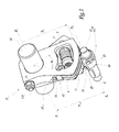
- the figure 1 shows a transmission device D according to the invention, which comprises a first member 1 adapted to be driven by a driving shaft 10, pivotally about a first axis X 1 -X ' 1 .
- the shaft 10 is said to "drive” because it is mechanically connected to a lever, not shown, operated by the pilot.
- the first member 1 is secured to the shaft 10 by means of a feather key 110, flat and eccentric thread, known per se and mounted in a housing 111 as is symbolized in FIG. figure 2 . He is therefore also called "leading".
- the device D also comprises a second member 2 having generally the shape of a cylindrical shaft adapted to pivot about a second axis X 2 -X ' 2 .
- the second axis X 2 -X ' 2 is substantially parallel to the axis X 1 -X' 1 , these two axes being separated by a spacing e 12 .
- the second member 2 is said to be “driven” because it is pivotally driven around the axis X 2 -X ' 2 by the driving member 1, when the pilot operates the lever.
- the device D To transmit, from the driving member 1 to the driven member 2, the rotational movement imparted to the lever by the pilot, the device D comprises an elongated element formed here of a first cable 4, whose structure and operation are detailed below.
- the device D further comprises a third member 3 adapted to pivot about the axis X 1 -X ' 1 .
- the first member 1 and the third member 3 each have, in section in a plane perpendicular to the axis X 1 -X ' 1 , generally in the form of a relatively flat and circular base angular portion of a cylinder; in other words, the shape of a "piece of cake".
- the thickness E 1 of the first member 1 and the thickness E 3 of the third member 3, measured in a direction parallel to the axis X 1 -X ' 1 are each of the order of 7 mm.
- the members 1 and 3 are superimposed in thickness, but only partially in an angular sector centered on the axis X 1 -X ' 1 .
- the positions of the members 1 and 3 about the axis X 1 -X ' 1 have an angular offset between them.
- the device D comprises a second cable 5, similar to the first cable 4, which makes it possible to transmit a rotational movement of the member 1 to the member 3, as is detailed hereinafter.
- the slice of the cylinder which forms the first member 1 defines a first curvilinear segment 11.
- the segment 11 extends over an angular sector whose angle ⁇ at the apex 1 is about 40 ° and has a circular profile radius R 1 of about 48 mm.
- the angle ⁇ 1 can be between 5 ° and 100 ° and the radius R 1 can be between 20 mm and 100 mm.
- the perimeter of the second member 2 defines a second curvilinear segment 21, in this case in the form of a complete circle, with an angle of 360 °.
- Segment 21 has a radius R 2 , visible at figure 3 , about 6 mm and extends over an angle ⁇ 2 , visible at the figure 5 being about 310 °.
- the radius R 2 may be between 5 mm and 100 mm and the angle ⁇ 2 may be between 5 ° and 310 °.
- the edge of the cylinder which forms the third member 3 defines a third curvilinear segment 31.
- the segment 31 extends over a angular sector whose angle at the apex ⁇ 3 is about 40 °, like the angle ⁇ 1 , and has a circular profile of radius R 3 equal to about 48 mm and identical to the radius R 1 .
- the angle ⁇ 3 can be between 5 ° and 100 ° and the radius R 3 can be between 20 mm and 100 mm.
- the reduction ratio R 1 / R 2 or conversely of reduction, between the driving and driven members is 7.4 (48.5 mm by 6.5 mm, which corresponds to the ratio of the primary windings), which is particularly high for a motion transmission mechanism associated with an aircraft shaft.
- the center distance e 12 which separates the axes X 1 -X ' 1 and X 2 -X' 2 , is approximately 55.5 mm.
- the spacing may be between 40 mm and 100 mm.
- the first, second and / or third curvilinear segment (s) 11, 21, 31 may have a profile other than circular, for example elliptical, spiral or parabolic.
- the shaft 10 passes through a cylindrical bore 101 of the member 1 and a cylindrical bore 103 of the member 2.
- the member 3 is rotatably mounted around the shaft 10 and the axis X 1 -X ' 1 .
- the member 3 is held against the member 1 by means of an elastic ring 19. The member 3 can thus pivot relative to the member 1 and around the axis X 1 -X ' 1 independently of the organ 1.
- the member 1 and the member 3 have, in a medial radial region located between the axis X 1 -X ' 1 and the segments 11 and 31, complementary recesses, respectively 16 and 36, of cylindrical shapes centered on the axis X 1 -X ' 1 .
- the recesses 16 and 36 are machined respectively in the thickness E 1 of the member 1 and in the thickness E 3 of the member 3.
- the recesses 16 and 36 constitute sliding paths for the first member 1 relative to the third member 3.
- the segments 11 and 31 are adjacent.
- the segment 31 forms a sort of extension of the segment 11 parallel to the axis X 1 -X ' 1 .
- the cable 4 is disposed on the segment 11 of the member 1 and on the segment 21 of the member 2.
- the cable 4 bears on the segments 11 and 21.
- the cable 4 is wound and "turn around” a lug 24 fixed in the segment 21 of the member 2.
- the cable 4 is thus connected to the lug 24 with the possibility of sliding around the lug 24.
- the cable 4 is wound and "turned” around a lug 14 secured to a side face 15 of the member 1, that is to say a face extending between the X axis 1 -X ' 1 and the segment 11.
- the two ends of the cable 4 are clamped at a splice 41 mounted near the lug 14, so as to fix the cable 4 to the first member 1.
- the cable 5 is disposed on the segment 21 of the member 2 and on the segment 31 of the member 3.
- the cable 5 bears on the segments 21 and 31.
- Au level of the second member 2 the cable 5 is wound and "turned” around a lug 25 fixed in the segment 21.
- the cable 5 is thus connected to the lug 25 with the possibility of sliding around the l 25.
- the cable 5 is wound and "turned” around a lug 34 secured to a lateral face 35 of the member 3, that is to say a face extending between the axis X 1 -X ' 1 and the segment 31.
- the two ends of the cable 5 are gripped at a splice 51 mounted near the pin 34, so as to fix the cable 5 to the third organ 3.
- the cables 4 and 5 together form an elongate and flexible element 6 which extends between the lugs 14 and 34, on the segments 11, 21 and 31.
- the element 6 is fixed to the members 1 and 3 at the lugs 14 and 34.
- the element 6 is connected to the driven member 2, at the lugs 24 and 25.
- the lugs 14, 24, 25 and 34 can be respectively crimped, screwed or integrally into or with the bodies 1, 2 and 3.
- the cables 4 and 5 are also arranged partly on the lateral faces 15 and 35 of the members 1 and 3, since they are fixed by the lugs 14 and 34. Consequently, each of the cables 4 and 5 extends over the junction between the lateral face 15 or 35 of the member 1 or 3 and the segment 11 or 31 respectively. As these junctions have small radii of curvature, the cables 4 and 5 should preferably be flexible.
- the main faces of the members 1 and 3 have ribs 12 and 32 which line the segments 11 and 31 on both their sides and which extend radially projecting beyond the surface of the segments 11 and 31.
- the ribs 12 and 32 form flanges and constitute guide means for the cables 4 and 5, in a direction parallel to the axis X 1 -X ' 1 , so as to ensure their maintenance on the segments 11 and 31.
- such means for guiding the elongated elements may be formed by one or more grooves machined on the surface of the curvilinear segments.
- the cables 4 and 5 are made of para-aramid, for example of the Kevlar® brand, so that they have a very high modulus of elasticity and therefore very little elastic deformation under the tensile forces applied to the cables in service. . Longiline elements thus formed can therefore be described as "inextensible”.
- the elongate elements of the device may be formed of braided strands.
- the element 6 is also inextensible since it is formed of the cables 4 and 5.
- the segments 11, 21 and 31 are made with a smooth current machining surface state, which avoids the abrasion of the cables 4 and 5 during the relative pivoting of the members 1 and 3.
- the device D further comprises a linear elastic element 7 of return, arranged between the members 1 and 3.
- the return element 7 is constituted by a stack of several Belleville washers mounted on a rod 71 and disposed within a housing 17 and a housing 37, respectively belonging to the bodies 1 and 3.
- the housing 17 is defined by a cavity passing through the member 1, while the housing 37 is defined by a rib 38 projecting from relative to a main face 39 of the organ 3.
- the ends of the spring 7 are fixed respectively on the members 1 and 3.
- the spring 7 works in compression, which tends to angularly move the members 1 and 3 from one another.
- the spring 7 keeps the cables 4 and 5 in tension, because it maximizes the curvilinear length on which they extend between their respective ends. This tension exerted on the cables 4 and 5 makes it possible to compensate for the angular clearance likely to appear between the members 1, 2 and / or 3 when the device D is in use.
- the device D is able to transmit, to the directional members of the aircraft, a rotational movement with zero clearance and low friction and constant, to the extent that each elongate member 4, 5 or 6 of the device D is inextensible.
- a device according to the invention provides improved ergonomics and steering sensations, especially since it eliminates the feeling of meshing felt with the devices of the prior art.
- the para-aramid cables are able to withstand very high temperatures and they have very little or no expansion, for operating temperatures between -40 ° C and + 70 ° C. This ensures a good "indexing" of the device D, that is to say a reproducible positioning of the driving member 1, the driven member 2 and the play catch member 3 relative to each other. .
- the first member 1 and the third member 3 may be made of ordinary steel or aluminum and the driven member 2 may be made of ordinary steel to transmit large torques. Such materials are inexpensive, unlike the special steels treated which constitute the gears of the devices of the prior art. Moreover, the driving members 1, led 2 and play catch 3 are less expensive parts to machine than the gears of the prior art.
- the friction possibly generated in a device according to the invention is substantially lower than that generated, for example, between the teeth of the gears of the prior art subjected to the forces exerted by the spring on the play catching sector. This further improves ergonomics and driving sensations by reducing the level and the ripple or fluctuation of this friction, especially for large maneuvering torques.
- a device according to the invention allows to transmit, without play or without “discarding”, a maneuvering torque of up to 10 Nm, while this torque is generally limited to 1.5 Nm in the prior art.
- a device according to the invention is able to withstand a maximum torque under ultimate load before breaking 1.5 times greater than the maximum torque transmittable by the gears of the prior art.
- defaussing is meant the failure of the backlash function in the case of a device of the prior art gears. In practice, this failure occurs when the driver applies, on the driving shaft, a maneuvering torque in a direction such that the forces are transmitted by the adjuster tooth sector and that this maneuvering torque produces on the catch-up spring a force greater than the preload of this spring.
- the device D object of the invention further comprises a stop screw 72 which is screwed into a tapping 73 made in the third member 3 and which takes up the forces between the first member 1 and the third member 3 when the capacity of the spring 7 is outdated.
- the first member comprises a housing 74, visible for example to figures 2 and 6 , of complementary shape to the head of the stop screw 73.
- a device according to the invention has a substantially increased endurance compared to gear devices of the prior art, due to reduced wear of moving parts, namely cables and driving, driven and
- a device according to the invention does not require lubrication for its operation.
- the Figures 4 to 6 illustrate three angular positions adopted by the device D during the operation of the lever by the pilot.
- the Figures 4 and 6 have distant angular positions and the figure 5 has a median angular position.
- the member 1 has an angular stroke ⁇ 1 of about 40 ° and the member 2 has an angular stroke ⁇ 2 of about 210 °.
- the radial axis defined by the lug 24 occupies a substantially vertical position in the reference of Figures 4 to 6 .
- the member 1 has an angular stroke of about 20 ° and the member 2 has an angular stroke of about 148 °.
- the device has an extreme position beyond the figure 4 , which is symmetrical to that reached beyond the figure 6 and described above. Between the two possible extreme positions, respectively beyond the figure 4 and beyond figure 6 , the member 1 thus performs a rotation of about 40 ° and the member 2 a rotation of about 296 °.
- the part of the cable 4 which extends between the first segment 11 and the second segment 21 does not come into contact with either the first segment 11 or the second segment 21.
- the contact between the cable 4 and the first segment 11 is interrupted at a point S 1 .
- the contact between the cable 5 and the third segment 31 is interrupted at a point S 3 .
- the dimensions of the members 1, 2 and 3, in particular the radii R 1 , R 2 and R 3 and the spacing e 12 are determined so as to minimize the distance S 1 -S 3 between the points S 1 and S 3 .
- the cable 4 or 5 is oriented substantially along the tangent to the second segment 21 at the point of contact.
- the force transmitted by the cable is carried by a direction substantially perpendicular to the respective radial directions of the members 1, 2 and 3 taken at the contact points, including S 1 and S 3 .
- each of the cables 4 and 5 can be replaced by a single-core wire terminated by a loop at each of its ends.
- the cables 4 and 5 may be replaced by a single cable disposed on the curvilinear segments of the first, second and third members.
- the elongated element ensuring the transmission of the rotational movement between the driving member and the driven member may consist of a relatively flat ribbon or a thicker braid.
- the device of the invention may have a geometry such that the elongate element winds helically, especially around the second member.
- the elongate element is formed by cables, which makes it possible to limit the size of such a device, the planes containing the neutral axis of the cables are then no longer perpendicular to the axes of the first and second members.
- Such a geometry makes it possible to increase the reduction ratio by conferring on the second member an angular travel of more than 360 °, without generating interference between the mechanical elements.
- a motion transmitting mechanism incorporating the device D may be incorporated into an aircraft for transmitting flight control commands from the cockpit.
Landscapes
- Engineering & Computer Science (AREA)
- Physics & Mathematics (AREA)
- General Physics & Mathematics (AREA)
- Automation & Control Theory (AREA)
- General Engineering & Computer Science (AREA)
- Mechanical Engineering (AREA)
- Transmission Devices (AREA)
- Input Circuits Of Receivers And Coupling Of Receivers And Audio Equipment (AREA)
- Mechanical Control Devices (AREA)
- Flexible Shafts (AREA)
Applications Claiming Priority (1)
| Application Number | Priority Date | Filing Date | Title |
|---|---|---|---|
| FR0854065A FR2932901B1 (fr) | 2008-06-19 | 2008-06-19 | Dispositif pour transmettre un mouvement de rotation et mecanisme de transmission comprenant un tel dispositif |
Publications (2)
| Publication Number | Publication Date |
|---|---|
| EP2136104A1 true EP2136104A1 (de) | 2009-12-23 |
| EP2136104B1 EP2136104B1 (de) | 2012-02-15 |
Family
ID=40430034
Family Applications (1)
| Application Number | Title | Priority Date | Filing Date |
|---|---|---|---|
| EP09162910A Active EP2136104B1 (de) | 2008-06-19 | 2009-06-17 | Vorrichtung zum Übertragen einer Drehbewegung und eine solche Vorrichtung umfassender Übertragungsmechanismus |
Country Status (4)
| Country | Link |
|---|---|
| EP (1) | EP2136104B1 (de) |
| AT (1) | ATE545902T1 (de) |
| ES (1) | ES2380886T3 (de) |
| FR (1) | FR2932901B1 (de) |
Cited By (1)
| Publication number | Priority date | Publication date | Assignee | Title |
|---|---|---|---|---|
| US20250060025A1 (en) * | 2021-12-21 | 2025-02-20 | Latecoere | Mechanical drive connection for driving a shaft in rotation by transmission under tension |
Citations (3)
| Publication number | Priority date | Publication date | Assignee | Title |
|---|---|---|---|---|
| EP0061216A2 (de) * | 1981-03-25 | 1982-09-29 | Philips Electronics Uk Limited | Einrichtung zur Einstellung des Wertes einer elektrischen Komponente |
| JPS60243875A (ja) * | 1984-05-17 | 1985-12-03 | Matsushita Electric Ind Co Ltd | メタルバンド取付装置 |
| WO1998055780A1 (de) * | 1997-06-06 | 1998-12-10 | Deutsches Zentrum für Luft- und Raumfahrt e.V. | Getriebeeinheit |
-
2008
- 2008-06-19 FR FR0854065A patent/FR2932901B1/fr not_active Expired - Fee Related
-
2009
- 2009-06-17 EP EP09162910A patent/EP2136104B1/de active Active
- 2009-06-17 ES ES09162910T patent/ES2380886T3/es active Active
- 2009-06-17 AT AT09162910T patent/ATE545902T1/de active
Patent Citations (3)
| Publication number | Priority date | Publication date | Assignee | Title |
|---|---|---|---|---|
| EP0061216A2 (de) * | 1981-03-25 | 1982-09-29 | Philips Electronics Uk Limited | Einrichtung zur Einstellung des Wertes einer elektrischen Komponente |
| JPS60243875A (ja) * | 1984-05-17 | 1985-12-03 | Matsushita Electric Ind Co Ltd | メタルバンド取付装置 |
| WO1998055780A1 (de) * | 1997-06-06 | 1998-12-10 | Deutsches Zentrum für Luft- und Raumfahrt e.V. | Getriebeeinheit |
Cited By (1)
| Publication number | Priority date | Publication date | Assignee | Title |
|---|---|---|---|---|
| US20250060025A1 (en) * | 2021-12-21 | 2025-02-20 | Latecoere | Mechanical drive connection for driving a shaft in rotation by transmission under tension |
Also Published As
| Publication number | Publication date |
|---|---|
| ES2380886T3 (es) | 2012-05-21 |
| EP2136104B1 (de) | 2012-02-15 |
| FR2932901B1 (fr) | 2010-07-30 |
| ATE545902T1 (de) | 2012-03-15 |
| FR2932901A1 (fr) | 2009-12-25 |
Similar Documents
| Publication | Publication Date | Title |
|---|---|---|
| EP2858897B1 (de) | Joystick zum steuern eines flugzeugs | |
| EP2526321B1 (de) | Reduktionsgetriebe und übertragungsmechanismus mit einem derartigen reduktionsgetriebe zur steuerung eines flugzeuges | |
| FR2938822A1 (fr) | Verin rotatif a loi d'effort integree et procede de reduction du jeu d'un tel verin rotatif. | |
| EP2864167B1 (de) | Elektromechanische bremse mit getriebespielkompensation | |
| WO2014161796A1 (fr) | Verin a cable permettant un debattement articulaire augmente | |
| EP3090190A2 (de) | Aktuator mit nichtumkehrbarem schrauben- und muttersystem, trommelbremse und bremsvorrichtung damit | |
| EP2485944B1 (de) | Flugzeugdrosselsteuerung mit einrastender rollenkupplung | |
| WO2016005134A2 (fr) | Actionneur electromecanique a limiteur de couple mecanique a rouleaux | |
| EP2829470B1 (de) | Vorrichtung zum Drehantrieb eines Luftfahrzeugrads | |
| FR2764358A1 (fr) | Dispositif pour actionner un arbre de commutation d'une boite de vitesses | |
| EP0521760B1 (de) | Vorrichtung zur Einstellung des Arbeitseffekts der Steuerorgane eines Luftfahrzeuges | |
| WO2010136708A2 (fr) | Dispositif de commande par cables d'une boite de vitesses mecanique pour vehicule automobile au moyen d'un levier | |
| EP3372491B1 (de) | Kraftmessvorrichtung und flugsteuerung, die eine solche kraftmessvorrichtung umfasst | |
| EP2136104B1 (de) | Vorrichtung zum Übertragen einer Drehbewegung und eine solche Vorrichtung umfassender Übertragungsmechanismus | |
| EP0734496B1 (de) | Automatisch nachstellbare strebe für eine trommelbremse | |
| EP0560645A1 (de) | Gangschalthebelvorrichtung, insbesondere für Kraftfahrzeuge | |
| EP3424822A1 (de) | Gassteuerungssystem eines luftfahrzeugs | |
| WO2016005135A2 (fr) | Actionneur electromecanique a dispositif de freinage double fonction | |
| EP1911992B1 (de) | Vorrichtung zur Übertragung von Bewegungen sowie entsprechende elektrische Ausstattung und entsprechendes Kraftfahrzeug | |
| WO1999047417A1 (fr) | Pale de rotor, notamment pour le rotor arriere anticouple d'un helicoptere | |
| FR2467767A1 (fr) | Manette de commande pour derailleur de cycle | |
| EP3467612B1 (de) | Vorrichtung zur erzeugung einer kraftempfindung durch reibung für ein flugsteuerungssystem eines luftfahrzeugs | |
| EP1533203A1 (de) | Exzentrischer Feststellbremshebel | |
| EP2349832B1 (de) | Vorrichtung zur kraftübertragung und vorrichtung zum antreiben einer solchen vorrichtung | |
| FR2705079A1 (fr) | Dispositif de commande pour frein et dérailleur de cycle. |
Legal Events
| Date | Code | Title | Description |
|---|---|---|---|
| PUAI | Public reference made under article 153(3) epc to a published international application that has entered the european phase |
Free format text: ORIGINAL CODE: 0009012 |
|
| AK | Designated contracting states |
Kind code of ref document: A1 Designated state(s): AT BE BG CH CY CZ DE DK EE ES FI FR GB GR HR HU IE IS IT LI LT LU LV MC MK MT NL NO PL PT RO SE SI SK TR |
|
| AX | Request for extension of the european patent |
Extension state: AL BA RS |
|
| 17P | Request for examination filed |
Effective date: 20100526 |
|
| REG | Reference to a national code |
Ref country code: DE Ref legal event code: R079 Ref document number: 602009005321 Country of ref document: DE Free format text: PREVIOUS MAIN CLASS: F16H0019000000 Ipc: G05G0023020000 |
|
| GRAP | Despatch of communication of intention to grant a patent |
Free format text: ORIGINAL CODE: EPIDOSNIGR1 |
|
| RIC1 | Information provided on ipc code assigned before grant |
Ipc: G05G 23/02 20060101AFI20110729BHEP |
|
| GRAS | Grant fee paid |
Free format text: ORIGINAL CODE: EPIDOSNIGR3 |
|
| GRAA | (expected) grant |
Free format text: ORIGINAL CODE: 0009210 |
|
| AK | Designated contracting states |
Kind code of ref document: B1 Designated state(s): AT BE BG CH CY CZ DE DK EE ES FI FR GB GR HR HU IE IS IT LI LT LU LV MC MK MT NL NO PL PT RO SE SI SK TR |
|
| AX | Request for extension of the european patent |
Extension state: AL BA RS |
|
| REG | Reference to a national code |
Ref country code: GB Ref legal event code: FG4D Free format text: NOT ENGLISH Ref country code: CH Ref legal event code: EP |
|
| REG | Reference to a national code |
Ref country code: IE Ref legal event code: FG4D Free format text: LANGUAGE OF EP DOCUMENT: FRENCH |
|
| REG | Reference to a national code |
Ref country code: AT Ref legal event code: REF Ref document number: 545902 Country of ref document: AT Kind code of ref document: T Effective date: 20120315 |
|
| REG | Reference to a national code |
Ref country code: DE Ref legal event code: R096 Ref document number: 602009005321 Country of ref document: DE Effective date: 20120419 |
|
| REG | Reference to a national code |
Ref country code: ES Ref legal event code: FG2A Ref document number: 2380886 Country of ref document: ES Kind code of ref document: T3 Effective date: 20120521 |
|
| REG | Reference to a national code |
Ref country code: NL Ref legal event code: VDEP Effective date: 20120215 |
|
| LTIE | Lt: invalidation of european patent or patent extension |
Effective date: 20120215 |
|
| PG25 | Lapsed in a contracting state [announced via postgrant information from national office to epo] |
Ref country code: HR Free format text: LAPSE BECAUSE OF FAILURE TO SUBMIT A TRANSLATION OF THE DESCRIPTION OR TO PAY THE FEE WITHIN THE PRESCRIBED TIME-LIMIT Effective date: 20120215 Ref country code: NO Free format text: LAPSE BECAUSE OF FAILURE TO SUBMIT A TRANSLATION OF THE DESCRIPTION OR TO PAY THE FEE WITHIN THE PRESCRIBED TIME-LIMIT Effective date: 20120515 Ref country code: LT Free format text: LAPSE BECAUSE OF FAILURE TO SUBMIT A TRANSLATION OF THE DESCRIPTION OR TO PAY THE FEE WITHIN THE PRESCRIBED TIME-LIMIT Effective date: 20120215 Ref country code: NL Free format text: LAPSE BECAUSE OF FAILURE TO SUBMIT A TRANSLATION OF THE DESCRIPTION OR TO PAY THE FEE WITHIN THE PRESCRIBED TIME-LIMIT Effective date: 20120215 Ref country code: IS Free format text: LAPSE BECAUSE OF FAILURE TO SUBMIT A TRANSLATION OF THE DESCRIPTION OR TO PAY THE FEE WITHIN THE PRESCRIBED TIME-LIMIT Effective date: 20120615 |
|
| PG25 | Lapsed in a contracting state [announced via postgrant information from national office to epo] |
Ref country code: GR Free format text: LAPSE BECAUSE OF FAILURE TO SUBMIT A TRANSLATION OF THE DESCRIPTION OR TO PAY THE FEE WITHIN THE PRESCRIBED TIME-LIMIT Effective date: 20120516 Ref country code: LV Free format text: LAPSE BECAUSE OF FAILURE TO SUBMIT A TRANSLATION OF THE DESCRIPTION OR TO PAY THE FEE WITHIN THE PRESCRIBED TIME-LIMIT Effective date: 20120215 Ref country code: PT Free format text: LAPSE BECAUSE OF FAILURE TO SUBMIT A TRANSLATION OF THE DESCRIPTION OR TO PAY THE FEE WITHIN THE PRESCRIBED TIME-LIMIT Effective date: 20120615 Ref country code: PL Free format text: LAPSE BECAUSE OF FAILURE TO SUBMIT A TRANSLATION OF THE DESCRIPTION OR TO PAY THE FEE WITHIN THE PRESCRIBED TIME-LIMIT Effective date: 20120215 Ref country code: FI Free format text: LAPSE BECAUSE OF FAILURE TO SUBMIT A TRANSLATION OF THE DESCRIPTION OR TO PAY THE FEE WITHIN THE PRESCRIBED TIME-LIMIT Effective date: 20120215 |
|
| REG | Reference to a national code |
Ref country code: IE Ref legal event code: FD4D |
|
| REG | Reference to a national code |
Ref country code: AT Ref legal event code: MK05 Ref document number: 545902 Country of ref document: AT Kind code of ref document: T Effective date: 20120215 |
|
| PG25 | Lapsed in a contracting state [announced via postgrant information from national office to epo] |
Ref country code: CY Free format text: LAPSE BECAUSE OF FAILURE TO SUBMIT A TRANSLATION OF THE DESCRIPTION OR TO PAY THE FEE WITHIN THE PRESCRIBED TIME-LIMIT Effective date: 20120215 |
|
| PG25 | Lapsed in a contracting state [announced via postgrant information from national office to epo] |
Ref country code: SI Free format text: LAPSE BECAUSE OF FAILURE TO SUBMIT A TRANSLATION OF THE DESCRIPTION OR TO PAY THE FEE WITHIN THE PRESCRIBED TIME-LIMIT Effective date: 20120215 Ref country code: IE Free format text: LAPSE BECAUSE OF FAILURE TO SUBMIT A TRANSLATION OF THE DESCRIPTION OR TO PAY THE FEE WITHIN THE PRESCRIBED TIME-LIMIT Effective date: 20120215 Ref country code: CZ Free format text: LAPSE BECAUSE OF FAILURE TO SUBMIT A TRANSLATION OF THE DESCRIPTION OR TO PAY THE FEE WITHIN THE PRESCRIBED TIME-LIMIT Effective date: 20120215 Ref country code: RO Free format text: LAPSE BECAUSE OF FAILURE TO SUBMIT A TRANSLATION OF THE DESCRIPTION OR TO PAY THE FEE WITHIN THE PRESCRIBED TIME-LIMIT Effective date: 20120215 Ref country code: DK Free format text: LAPSE BECAUSE OF FAILURE TO SUBMIT A TRANSLATION OF THE DESCRIPTION OR TO PAY THE FEE WITHIN THE PRESCRIBED TIME-LIMIT Effective date: 20120215 Ref country code: SE Free format text: LAPSE BECAUSE OF FAILURE TO SUBMIT A TRANSLATION OF THE DESCRIPTION OR TO PAY THE FEE WITHIN THE PRESCRIBED TIME-LIMIT Effective date: 20120215 Ref country code: EE Free format text: LAPSE BECAUSE OF FAILURE TO SUBMIT A TRANSLATION OF THE DESCRIPTION OR TO PAY THE FEE WITHIN THE PRESCRIBED TIME-LIMIT Effective date: 20120215 |
|
| PG25 | Lapsed in a contracting state [announced via postgrant information from national office to epo] |
Ref country code: IT Free format text: LAPSE BECAUSE OF FAILURE TO SUBMIT A TRANSLATION OF THE DESCRIPTION OR TO PAY THE FEE WITHIN THE PRESCRIBED TIME-LIMIT Effective date: 20120215 Ref country code: SK Free format text: LAPSE BECAUSE OF FAILURE TO SUBMIT A TRANSLATION OF THE DESCRIPTION OR TO PAY THE FEE WITHIN THE PRESCRIBED TIME-LIMIT Effective date: 20120215 |
|
| PLBE | No opposition filed within time limit |
Free format text: ORIGINAL CODE: 0009261 |
|
| STAA | Information on the status of an ep patent application or granted ep patent |
Free format text: STATUS: NO OPPOSITION FILED WITHIN TIME LIMIT |
|
| BERE | Be: lapsed |
Owner name: SKF AEROSPACE FRANCE Effective date: 20120630 |
|
| 26N | No opposition filed |
Effective date: 20121116 |
|
| PG25 | Lapsed in a contracting state [announced via postgrant information from national office to epo] |
Ref country code: AT Free format text: LAPSE BECAUSE OF FAILURE TO SUBMIT A TRANSLATION OF THE DESCRIPTION OR TO PAY THE FEE WITHIN THE PRESCRIBED TIME-LIMIT Effective date: 20120215 Ref country code: MC Free format text: LAPSE BECAUSE OF NON-PAYMENT OF DUE FEES Effective date: 20120630 |
|
| PG25 | Lapsed in a contracting state [announced via postgrant information from national office to epo] |
Ref country code: MK Free format text: LAPSE BECAUSE OF FAILURE TO SUBMIT A TRANSLATION OF THE DESCRIPTION OR TO PAY THE FEE WITHIN THE PRESCRIBED TIME-LIMIT Effective date: 20120215 |
|
| REG | Reference to a national code |
Ref country code: DE Ref legal event code: R097 Ref document number: 602009005321 Country of ref document: DE Effective date: 20121116 |
|
| PG25 | Lapsed in a contracting state [announced via postgrant information from national office to epo] |
Ref country code: BE Free format text: LAPSE BECAUSE OF NON-PAYMENT OF DUE FEES Effective date: 20120630 |
|
| REG | Reference to a national code |
Ref country code: DE Ref legal event code: R082 Ref document number: 602009005321 Country of ref document: DE Representative=s name: KOHL, THOMAS, DIPL.-ING. UNIV., DE Effective date: 20130529 Ref country code: DE Ref legal event code: R081 Ref document number: 602009005321 Country of ref document: DE Owner name: FLY BY WIRE SYSTEMS FRANCE, FR Free format text: FORMER OWNER: SKF AEROSPACE FRANCE, SAINT VALLIER SUR RHONE, FR Effective date: 20130529 Ref country code: DE Ref legal event code: R082 Ref document number: 602009005321 Country of ref document: DE Representative=s name: LAVOIX MUNICH, DE Effective date: 20130529 |
|
| PG25 | Lapsed in a contracting state [announced via postgrant information from national office to epo] |
Ref country code: BG Free format text: LAPSE BECAUSE OF FAILURE TO SUBMIT A TRANSLATION OF THE DESCRIPTION OR TO PAY THE FEE WITHIN THE PRESCRIBED TIME-LIMIT Effective date: 20120515 Ref country code: MT Free format text: LAPSE BECAUSE OF FAILURE TO SUBMIT A TRANSLATION OF THE DESCRIPTION OR TO PAY THE FEE WITHIN THE PRESCRIBED TIME-LIMIT Effective date: 20120215 |
|
| REG | Reference to a national code |
Ref country code: FR Ref legal event code: TP Owner name: FLY BY WIRE SYSTEMS FRANCE, FR Effective date: 20130701 |
|
| REG | Reference to a national code |
Ref country code: ES Ref legal event code: PC2A Owner name: FLY BY WIRE SYTEMS FRANCE Effective date: 20130808 |
|
| REG | Reference to a national code |
Ref country code: GB Ref legal event code: 732E Free format text: REGISTERED BETWEEN 20130905 AND 20130911 |
|
| REG | Reference to a national code |
Ref country code: CH Ref legal event code: PL |
|
| PG25 | Lapsed in a contracting state [announced via postgrant information from national office to epo] |
Ref country code: CH Free format text: LAPSE BECAUSE OF NON-PAYMENT OF DUE FEES Effective date: 20130630 Ref country code: LI Free format text: LAPSE BECAUSE OF NON-PAYMENT OF DUE FEES Effective date: 20130630 Ref country code: TR Free format text: LAPSE BECAUSE OF FAILURE TO SUBMIT A TRANSLATION OF THE DESCRIPTION OR TO PAY THE FEE WITHIN THE PRESCRIBED TIME-LIMIT Effective date: 20120215 |
|
| PG25 | Lapsed in a contracting state [announced via postgrant information from national office to epo] |
Ref country code: LU Free format text: LAPSE BECAUSE OF NON-PAYMENT OF DUE FEES Effective date: 20120617 |
|
| PG25 | Lapsed in a contracting state [announced via postgrant information from national office to epo] |
Ref country code: HU Free format text: LAPSE BECAUSE OF FAILURE TO SUBMIT A TRANSLATION OF THE DESCRIPTION OR TO PAY THE FEE WITHIN THE PRESCRIBED TIME-LIMIT Effective date: 20090617 |
|
| REG | Reference to a national code |
Ref country code: DE Ref legal event code: R082 Ref document number: 602009005321 Country of ref document: DE Representative=s name: LAVOIX MUNICH, DE |
|
| REG | Reference to a national code |
Ref country code: FR Ref legal event code: PLFP Year of fee payment: 8 |
|
| REG | Reference to a national code |
Ref country code: FR Ref legal event code: PLFP Year of fee payment: 9 |
|
| REG | Reference to a national code |
Ref country code: FR Ref legal event code: PLFP Year of fee payment: 10 |
|
| REG | Reference to a national code |
Ref country code: DE Ref legal event code: R081 Ref document number: 602009005321 Country of ref document: DE Owner name: LORD SOLUTIONS FRANCE, FR Free format text: FORMER OWNER: FLY BY WIRE SYSTEMS FRANCE, SAINT-VALLIER, FR Ref country code: DE Ref legal event code: R082 Ref document number: 602009005321 Country of ref document: DE Representative=s name: LAVOIX MUNICH, DE |
|
| REG | Reference to a national code |
Ref country code: DE Ref legal event code: R082 Ref document number: 602009005321 Country of ref document: DE |
|
| REG | Reference to a national code |
Ref country code: DE Ref legal event code: R082 Ref document number: 602009005321 Country of ref document: DE Representative=s name: HOEFER & PARTNER PATENTANWAELTE MBB, DE Ref country code: DE Ref legal event code: R081 Ref document number: 602009005321 Country of ref document: DE Owner name: CROUZET, FR Free format text: FORMER OWNER: LORD SOLUTIONS FRANCE, PONT-DE-L'ISERE, FR |
|
| REG | Reference to a national code |
Ref country code: GB Ref legal event code: 732E Free format text: REGISTERED BETWEEN 20240912 AND 20240918 |
|
| PGFP | Annual fee paid to national office [announced via postgrant information from national office to epo] |
Ref country code: DE Payment date: 20250509 Year of fee payment: 17 |
|
| PGFP | Annual fee paid to national office [announced via postgrant information from national office to epo] |
Ref country code: GB Payment date: 20250508 Year of fee payment: 17 |
|
| PGFP | Annual fee paid to national office [announced via postgrant information from national office to epo] |
Ref country code: FR Payment date: 20250512 Year of fee payment: 17 |
|
| PGFP | Annual fee paid to national office [announced via postgrant information from national office to epo] |
Ref country code: ES Payment date: 20250709 Year of fee payment: 17 |