EP2136088A2 - Connection element with a screw and an undetachable attached casing - Google Patents
Connection element with a screw and an undetachable attached casing Download PDFInfo
- Publication number
- EP2136088A2 EP2136088A2 EP09162495A EP09162495A EP2136088A2 EP 2136088 A2 EP2136088 A2 EP 2136088A2 EP 09162495 A EP09162495 A EP 09162495A EP 09162495 A EP09162495 A EP 09162495A EP 2136088 A2 EP2136088 A2 EP 2136088A2
- Authority
- EP
- European Patent Office
- Prior art keywords
- sleeve
- connecting element
- screw
- threaded portion
- thread
- Prior art date
- Legal status (The legal status is an assumption and is not a legal conclusion. Google has not performed a legal analysis and makes no representation as to the accuracy of the status listed.)
- Granted
Links
- 238000004519 manufacturing process Methods 0.000 claims abstract description 11
- 238000000034 method Methods 0.000 claims abstract description 6
- 239000000463 material Substances 0.000 claims description 21
- 230000002093 peripheral effect Effects 0.000 claims description 7
- 230000015572 biosynthetic process Effects 0.000 claims description 5
- 238000005096 rolling process Methods 0.000 claims description 4
- 238000002788 crimping Methods 0.000 claims description 2
- 239000011324 bead Substances 0.000 description 13
- 238000013461 design Methods 0.000 description 10
- 238000012549 training Methods 0.000 description 7
- 239000002184 metal Substances 0.000 description 6
- 238000006073 displacement reaction Methods 0.000 description 4
- 238000007373 indentation Methods 0.000 description 4
- 238000003825 pressing Methods 0.000 description 4
- 238000003780 insertion Methods 0.000 description 3
- 230000037431 insertion Effects 0.000 description 3
- 230000008569 process Effects 0.000 description 3
- 239000007787 solid Substances 0.000 description 3
- 230000007704 transition Effects 0.000 description 3
- 230000004323 axial length Effects 0.000 description 2
- 230000000295 complement effect Effects 0.000 description 2
- 230000001681 protective effect Effects 0.000 description 2
- 241000209035 Ilex Species 0.000 description 1
- 230000009471 action Effects 0.000 description 1
- 230000006978 adaptation Effects 0.000 description 1
- 230000005540 biological transmission Effects 0.000 description 1
- 238000005520 cutting process Methods 0.000 description 1
- 230000000994 depressogenic effect Effects 0.000 description 1
- 238000001514 detection method Methods 0.000 description 1
- 238000011161 development Methods 0.000 description 1
- 230000018109 developmental process Effects 0.000 description 1
- 238000005553 drilling Methods 0.000 description 1
- 230000000694 effects Effects 0.000 description 1
- 230000005489 elastic deformation Effects 0.000 description 1
- 238000004049 embossing Methods 0.000 description 1
- 230000003116 impacting effect Effects 0.000 description 1
- 230000003993 interaction Effects 0.000 description 1
- 230000014759 maintenance of location Effects 0.000 description 1
- 238000002360 preparation method Methods 0.000 description 1
- 238000004080 punching Methods 0.000 description 1
- 230000009467 reduction Effects 0.000 description 1
- 238000007493 shaping process Methods 0.000 description 1
- 230000035939 shock Effects 0.000 description 1
- 239000007858 starting material Substances 0.000 description 1
- 238000005482 strain hardening Methods 0.000 description 1
- 230000008093 supporting effect Effects 0.000 description 1
- 210000002105 tongue Anatomy 0.000 description 1
- 238000004804 winding Methods 0.000 description 1
Images


Classifications
-
- F—MECHANICAL ENGINEERING; LIGHTING; HEATING; WEAPONS; BLASTING
- F16—ENGINEERING ELEMENTS AND UNITS; GENERAL MEASURES FOR PRODUCING AND MAINTAINING EFFECTIVE FUNCTIONING OF MACHINES OR INSTALLATIONS; THERMAL INSULATION IN GENERAL
- F16B—DEVICES FOR FASTENING OR SECURING CONSTRUCTIONAL ELEMENTS OR MACHINE PARTS TOGETHER, e.g. NAILS, BOLTS, CIRCLIPS, CLAMPS, CLIPS OR WEDGES; JOINTS OR JOINTING
- F16B41/00—Measures against loss of bolts, nuts, or pins; Measures against unauthorised operation of bolts, nuts or pins
- F16B41/002—Measures against loss of bolts, nuts or pins
-
- Y—GENERAL TAGGING OF NEW TECHNOLOGICAL DEVELOPMENTS; GENERAL TAGGING OF CROSS-SECTIONAL TECHNOLOGIES SPANNING OVER SEVERAL SECTIONS OF THE IPC; TECHNICAL SUBJECTS COVERED BY FORMER USPC CROSS-REFERENCE ART COLLECTIONS [XRACs] AND DIGESTS
- Y10—TECHNICAL SUBJECTS COVERED BY FORMER USPC
- Y10T—TECHNICAL SUBJECTS COVERED BY FORMER US CLASSIFICATION
- Y10T29/00—Metal working
- Y10T29/49—Method of mechanical manufacture
- Y10T29/49826—Assembling or joining
- Y10T29/49947—Assembling or joining by applying separate fastener
- Y10T29/49963—Threaded fastener
-
- Y—GENERAL TAGGING OF NEW TECHNOLOGICAL DEVELOPMENTS; GENERAL TAGGING OF CROSS-SECTIONAL TECHNOLOGIES SPANNING OVER SEVERAL SECTIONS OF THE IPC; TECHNICAL SUBJECTS COVERED BY FORMER USPC CROSS-REFERENCE ART COLLECTIONS [XRACs] AND DIGESTS
- Y10—TECHNICAL SUBJECTS COVERED BY FORMER USPC
- Y10T—TECHNICAL SUBJECTS COVERED BY FORMER US CLASSIFICATION
- Y10T29/00—Metal working
- Y10T29/49—Method of mechanical manufacture
- Y10T29/49826—Assembling or joining
- Y10T29/49947—Assembling or joining by applying separate fastener
- Y10T29/49966—Assembling or joining by applying separate fastener with supplemental joining
Definitions
- This Rohhülse is characterized in that the two mutually facing ends of the strip of material still have a significant or comparatively larger distance, just a larger gap, as it shows the finished sleeve on the screw and thus on the connecting element.
- the extent enlarged gap is dimensioned so that a screw can be inserted or pushed into the interior of the Rohhülse without the tips of the threads of the threaded portion abut against the inner wall of the sleeve and in particular to the already formally completed bottlenecks.
- the insertion of the screw into the raw sleeve can be done in particular so that the bottlenecks of the sleeve are not the threaded portion, but the shank portion of the screw opposite.
- the screw can through the two bottlenecks and thereby acting Frictional forces also be held against rotation, which, however, can be overcome during the screwing of the screws in the other associated component.
- Frictional forces also be held against rotation, which, however, can be overcome during the screwing of the screws in the other associated component.
- a screw of a connecting element in the final assembly either targeted by a correspondingly dimensioned axial force relative to Insert sleeve in this and in the entrance of the threaded hole in the other associated component without the first thread would be damaged or squashed.
- the impressions 12 are here also formed as resilient elements 15, wherein on the one hand form the surface elements 13 in a non-resilient region and on the other hand represent the free ends 16 of the resilient elements 15 in the free end region. It is understood that the vote is carefully dimensioned and designed each other accordingly.
- the free ends 16 are not arranged gradient, so lie in the axial direction on a common circumferential line or plane.
- the free ends 16 of the resilient elements 15 may be provided in the manner shown with different acting inclined surfaces, so that over-snapping over the tips of the threads of the thread 8 is possible only in one direction.
Abstract
Description
Die Erfindung betrifft ein Verbindungselement mit einer Schraube und einer Hülse. Die Schraube weist einen Kopf, einen Schaftabschnitt und einen Gewindeabschnitt mit einem Gewinde auf. Der Schaftabschnitt ist dem Kopf zugekehrt und der Gewindeabschnitt von dem Kopf abgekehrt angeordnet. Der Schaftabschnitt besitzt einen Durchmesser, der kleiner als der Außendurchmesser des Gewindes des Gewindeabschnitts ist. Die Hülse besitzt eine erste Engstelle mit einem Durchmesser, der kleiner als der Außendurchmesser des Gewindes des Gewindeabschnitts ist.The invention relates to a connecting element with a screw and a sleeve. The screw has a head, a shank portion and a threaded portion with a thread. The shank portion faces the head and the threaded portion faces away from the head. The shank portion has a diameter that is smaller than the outer diameter of the thread of the threaded portion. The sleeve has a first throat with a diameter that is smaller than the outer diameter of the thread of the threaded portion.
Im Rahmen der vorliegenden Erfindung ist immer dann von einem "Verbindungselement" die Rede, wenn eine Schraube und eine Hülse zu einem Element verbunden sind. Ein solches Verbindungselement kann dann insbesondere zu mehreren in eine Transportstellung gelangen, in der es vom Schraubenhersteller z. B. an einen weiteren Hersteller geliefert wird, der insbesondere mehrere solche Verbindungselemente mit einem Bauteil - insbesondere einem Deckel, einer Haube oder dergleichen - zu einer vormontierten Baueinheit montiert. Die "vormontierte Baueinheit" besteht also aus einem Bauteil mit in der Regel mehreren daran montierten Verbindungselementen. Auch diese vormontierte Baueinheit gelangt dann wiederum in eine Transportstellung, z. B. zu einem Automobilhersteller, in dessen Montagelinie die vormontierte Baueinheit mit einem zugehörigen anderen Bauteil - insbesondere einem Unterteil - wie einem Zylinderblock, einem Getriebegehäuse oder dergleichen, verbunden wird. Bei dieser "Endmontage" werden die Schrauben der Verbindungselemente an der vormontierten Baueinheit insbesondere in Gewindelöcher im zugehörigen anderen Bauteil eingeschraubt.In the context of the present invention, a "connecting element" is always mentioned when a screw and a sleeve are connected to form an element. Such a connecting element can then in particular reach several into a transport position in which it can be used by the screw manufacturer z. B. is supplied to another manufacturer, in particular a plurality of such fasteners with a component - in particular a cover, a hood or the like - mounted to a preassembled unit. The "preassembled unit" thus consists of a component with usually several mounted thereon fasteners. These preassembled unit then again enters a transport position, eg. B. to an automobile manufacturer, in the assembly line, the preassembled unit with an associated other component - in particular a lower part - such as a cylinder block, a transmission housing or the like, is connected. In this "final assembly" the screws of the connecting elements are screwed to the preassembled unit in particular in threaded holes in the associated other component.
Ein Verbindungselement ist aus der
Ein weiteres Verbindungselement ist aus der
Aus der
Die
Der Erfindung liegt die Aufgabe zugrunde, ein Verbindungselement, ein Verfahren zu dessen Herstellung sowie eine vormontierte Baueinheit bereitzustellen, bei denen die Schraube und die Hülse stets unverlierbar miteinander verbunden sind und die Schraube in der unmontierten Stellung - abgesehen von der Unverlierbarkeit - axial frei relativ zu der Hülse beweglich, in der vormontierten Stellung der Hülse in einer Bohrung eines Bauteils jedoch relativ zu der Hülse axial definiert festsetzbar ist.The invention has for its object to provide a connecting element, a method for its preparation and a preassembled unit in which the screw and the sleeve are always connected captive and the screw in the unmounted position - apart from the captive - axially free relative to the sleeve movable, in the preassembled position of the sleeve in a bore of a component, however, defined axially relative to the sleeve can be fixed.
Die Aufgabe der Erfindung wird erfindungsgemäß mit den Merkmalen der unabhängigen Patentansprüche 1, 10 bzw. 11 gelöst.The object of the invention is achieved with the features of the
Die Erfindung betrifft ein Verbindungselement mit einer Schraube und einer Hülse, eine vormontierte Baueinheit mit einem solchen Verbindungselement und einem Bauteil mit einer Bohrung sowie ein Verfahren zur Herstellung des Verbindungselements. Die Schraube weist einen Kopf, einen Schaftabschnitt und einen Gewindeabschnitt mit einem Gewinde auf. Der Schaftabschnitt ist dem Kopf zugekehrt und der Gewindeabschnitt von dem Kopf abgekehrt angeordnet. Der Schaftabschnitt besitzt einen Durchmesser, der kleiner als der Außendurchmesser des Gewindes des Gewindeabschnitts ist. Die Hülse besitzt eine erste Engstelle mit einem Durchmesser, der kleiner als der Außendurchmesser des Gewindes des Gewindeabschnitts ist. Die Hülse weist weiterhin ein federndes Element mit einem Betätigungsbereich und einem Eingriffsbereich auf. In einer unmontierten Stellung des Verbindungselements steht der Betätigungsbereich derart aus der äußeren Umfangsfläche der Hülse heraus, dass der Eingriffsbereich nicht in das Gewinde des Gewindeabschnitts eingreift. In einer vormontierten Stellung des Verbindungselements in einer Bohrung eines Bauteils ist der Betätigungsbereich derart nach innen gedrückt, dass der Eingriffsbereich in das Gewinde des Gewindeabschnitts eingreift.The invention relates to a connecting element with a screw and a sleeve, a preassembled unit with such a connecting element and a component with a Bore and a method for producing the connecting element. The screw has a head, a shank portion and a threaded portion with a thread. The shank portion faces the head and the threaded portion faces away from the head. The shank portion has a diameter that is smaller than the outer diameter of the thread of the threaded portion. The sleeve has a first throat with a diameter that is smaller than the outer diameter of the thread of the threaded portion. The sleeve further comprises a resilient member having an actuating portion and an engaging portion. In an unmounted position of the connecting member, the operating portion projects out of the outer peripheral surface of the sleeve such that the engaging portion does not engage the thread of the threaded portion. In a preassembled position of the connecting element in a bore of a component, the actuating region is pressed inwards in such a way that the engagement region engages in the thread of the threaded section.
Es hat sich gezeigt, dass es in bestimmten Anwendungsfällen wünschenswert ist, die Schraube so in der Hülse definiert zu positionieren, dass die Schraube mit ihrem dem Kopf abgewandten freien Ende nicht aus der Hülse herausragt. Ein solcher Anwendungsfall liegt z. B. bei einer vormontierten Baueinheit vor, d. h. bei einem ersten Bauteil mit einer Bohrung, in die die Hülse eingepresst ist. Diese vormontierte Baueinheit soll im Rahmen der Endmontage insbesondere mit einer Mehrzahl von Verbindungselementen mit einem zweiten Bauteil verschraubt werden. Durch diese definierte Lage der Schraube relativ zu der Hülse und dem ersten Bauteil kann die vormontierte Baueinheit frei über dem zweiten Bauteil verschoben bzw. positioniert werden. Eine etwaige Beschädigung der Montagefläche des zweiten Bauteils wird zuverlässig vermieden.It has been found that in certain applications it is desirable to position the screw so defined in the sleeve that the screw with its free end facing away from the head does not protrude from the sleeve. Such an application is z. B. in a preassembled unit before, d. H. in a first component having a bore into which the sleeve is pressed. This preassembled unit is to be screwed in the context of final assembly in particular with a plurality of connecting elements with a second component. Through this defined position of the screw relative to the sleeve and the first component, the preassembled unit can be moved or positioned freely over the second component. Any damage to the mounting surface of the second component is reliably avoided.
Gleichzeitig hat sich aber herausgestellt, dass es gewünscht sein kann, dass die Schraube mit Ausnahme der Verliersicherung durch die erste Engstelle in der unmontierten Stellung des Verbindungselements - d. h. in einer Stellung, in der die Hülse nicht in eine Bohrung eines Bauteils eingepresst ist - frei relativ zu der Hülse in axialer Richtung verschieblich ist. Hierdurch kann die Hülse eine frei wählbare Position relativ zu der Schraube einnehmen, insbesondere eine Position, in der die Hülse mit ihrem entsprechenden Ende an der Kopfauflagefläche des Kopfs der Schraube anliegt. In dieser Stellung wird dann die Hülse in die entsprechende Bohrung des Bauteils eingepresst. Um die zuvor beschriebene andere Stellung zu erreichen, in der der Kopf der Schraube von der Hülse freikommt - oder anders gesagt das abgewandte freie Ende der Schraube in die Hülse eintritt - wird die Schraube relativ zu der Hülse und dem Bauteil weg gezogen bzw. die Schraube in die Hülse hineingedrückt.At the same time, however, it has been found that it may be desirable that the screw, with the exception of the captive by the first bottleneck in the unmounted position of the connecting element - ie in a position in which the sleeve is not pressed into a bore of a component - free relative is displaceable to the sleeve in the axial direction. In this way, the sleeve can assume a freely selectable position relative to the screw, in particular a position in which the sleeve bears with its corresponding end against the head support surface of the head of the screw. In this position, the sleeve is then pressed into the corresponding bore of the component. In order to achieve the other position described above, in which the head of the screw is released from the sleeve - or in other words, the remote free At the end of the screw enters the sleeve - the screw is pulled away relative to the sleeve and the component or the screw is pressed into the sleeve.
In der vormontieren Stellung des Verbindungselements mit in eine Bohrung eines Bauteils eingepresster Hülse weist das erfindungsgemäße Verbindungselement hülsenseitig also zwei Engstellen auf, von denen die eine Engstelle vorzugsweise nicht-federnd und die andere Engstelle federnd-nachgiebig ausgebildet ist. Beide Engstellen arbeiten mit dem an der Schraube ohnehin vorhandenen Gewindeabschnitt zusammen und sind auf diesen in besonderer Weise abgestimmt. Die erste Engstelle bildet mit dem kopfseitigen Endbereich des Gewindeabschnitts eine Anschlagpaarung im Sinne eines Anschlags und eines Gegenanschlags, der die Unverlierbarkeit sichert, in dieser Richtung wirkt und durch normalerweise auftretende Kräfte nicht überwunden werden kann. Die zweite Engstelle ist federnd-nachgiebig ausgebildet, wobei die freien Enden der federnden Elemente über die Spitzen der Gewindegänge des Gewindeabschnitts hinübertreten bzw. -ratschen können. Dies gilt zumindest in der einen Richtung, wenn die Schraube aus der Hülse teilweise herausgezogen oder herausgedrückt wird. Das Heraustreten wird durch Anschlagen der Anschlagpaarung der ersten Engstelle beendet. Damit wird die begrenzte axiale Verschiebbarkeit im Stand der Technik beseitigt oder reduziert. In der anderen Richtung, also beim weiteren Hineinschieben der Schraube in die Hülse kann je nach Gestaltung der freien Enden der federnden Elemente eine solche Bewegung zugelassen oder verhindert werden. Wenn die freien Enden widerhakenartig ausgebildet sind, wird diese Bewegung verhindert, so dass bei der Endmontage die Schraube vorteilhaft nur in die Hülse hineindreht und nicht hineingedrückt werden kann.In the preassembled position of the connecting element with pressed-in a bore of a component sleeve, the connecting element according to the invention on the sleeve side so two bottlenecks, of which one bottleneck is preferably non-resilient and the other bottleneck resiliently yielding. Both bottlenecks work together with the existing on the screw threaded portion anyway and are tuned to this in a special way. The first constriction forms with the head end portion of the threaded portion a pair of stops in the sense of a stop and a counter-attack, which secures the captive, acts in this direction and can not be overcome by normally occurring forces. The second constriction is resiliently yielding, wherein the free ends of the resilient elements over the tips of the threads of the threaded portion can pass or ratchet. This is true at least in one direction when the screw is partially pulled out of the sleeve or pushed out. The emergence is terminated by striking the stop pairing of the first bottleneck. Thus, the limited axial displaceability in the prior art is eliminated or reduced. In the other direction, so the further insertion of the screw in the sleeve can be allowed or prevented depending on the design of the free ends of the resilient elements such movement. If the free ends are barb-like, this movement is prevented, so that in the final assembly, the screw advantageously only rotates into the sleeve and can not be pressed.
Die beiden Engstellen dienen also zur Sicherung der Relativposition zwischen Schraube und Hülse in unterschiedliche Richtungen. Die erste Engstelle bildet einen Anschlag im Sinne einer Verliersicherung und verhindert ein Heraustreten der Schraube nach oben aus der Hülse heraus bzw. das Abfallen der Hülse über das dem Kopf abgewandte freie Ende der Schraube. Die erst im vormontierten Zustand der Hülse in einer Bohrung wirksam werdende zweite Engstelle dient hingegen der Erreichung und Beibehaltung einer definierten Position der Schraube relativ zu der Hülse - oder anders gesagt verhindert damit auch eine unerwünschte Relativbewegung der Schraube in die Hülse hinein. Die Schraube kann also in der maximal aus der Hülse herausgezogenen bzw. herausgedrückten Position selbsthemmend verbleiben. Diese Funktion des federnden Elements ist in der freien Stellung der Hülse noch nicht aktiviert, so dass in dieser Stellung Schraube und Hülse - abgesehen von der Verliersicherung - frei relativ zueinander positioniert werden können. Diese freie Positionierbarkeit ist insbesondere für den Vorgang des Einpressens der Hülse in eine Bohrung eines Bauteils bei der Vormontage gewünscht.The two bottlenecks thus serve to secure the relative position between the screw and sleeve in different directions. The first bottleneck forms a stop in the sense of a captive and prevents the screw from coming out of the sleeve or falling off the sleeve over the free end of the screw facing away from the head. By contrast, the second bottleneck acting only in the preassembled state of the sleeve in a bore serves to achieve and maintain a defined position of the screw relative to the sleeve - or in other words also prevents an unwanted relative movement of the screw into the sleeve. The screw can thus remain self-locking in the maximum position pulled out or pushed out of the sleeve. This function of the resilient element is not activated in the free position of the sleeve, so that in this position screw and sleeve - apart from the captive - free relative can be positioned to each other. This free positioning is particularly desired for the process of pressing the sleeve into a bore of a component during pre-assembly.
Die Hülse des Verbindungselements weist mindestens ein federndes Element, insbesondere ein radial federndes Element, auf. Es kann aber eine Mehrzahl federnder Elemente vorgesehen sein, insbesondere zwei, drei oder vier Elemente. Bevorzugt ist eine Ausführungsform mit zwei federnden Elementen. Diese sind zweckmäßigerweise gegenüberliegend am Umfang der Hülse angeordnet.The sleeve of the connecting element has at least one resilient element, in particular a radially resilient element. However, it can be provided a plurality of resilient elements, in particular two, three or four elements. Preferred is an embodiment with two resilient elements. These are expediently arranged opposite one another on the circumference of the sleeve.
Die Ausbildung des federnden Elements im Sinne seines Verformungsverhaltens kann dabei unterschiedlich gewählt werden. Eine erste bevorzugte Möglichkeit besteht darin, das federnde Element so auszubilden, dass es beim Einpressen der Hülse in die Bohrung und der entsprechenden Kontaktierung des Betätigungsbereichs des federnden Elements durch die Bohrungswandung ausschließlich einer elastischen Verformung unterliegt. Denkbar ist jedoch auch eine elastisch-plastische Verformung.The design of the resilient element in terms of its deformation behavior can be chosen differently. A first preferred possibility is to design the resilient element in such a way that when the sleeve is pressed into the bore and the corresponding contacting of the actuating region of the resilient element by the bore wall is subject exclusively to elastic deformation. However, it is also conceivable an elastic-plastic deformation.
Es kommen insbesondere normale Schrauben - im Gegensatz zu Spezialschrauben - zum Einsatz, die neben einem Kopf und einem Schaftabschnitt einen Gewindeabschnitt und in der Regel an dessen freien Ende auch einen Zentrierfortsatz aufweisen. Beide Engstellen der Hülse arbeiten mit Bereichen des Gewindeabschnitts zusammen, insbesondere mit solchen Gewindeabschnitten, die dem Kopf der Schraube zugekehrt angeordnet sind. So kann die erste Engstelle im Bereich des kopfseitigen Gewindeauslaufs des Gewindeabschnitts angreifen. Auch für die zweite Engstelle kann es vorteilhaft sein, mit einem Bereich des Gewindeabschnitts in Wirkkontakt zu treten, der kopfseitig angeordnet ist.There are in particular normal screws - in contrast to special screws - are used, which in addition to a head and a shaft portion have a threaded portion and usually at the free end and a centering extension. Both bottlenecks of the sleeve cooperate with areas of the threaded portion, in particular with such threaded portions which are arranged facing the head of the screw. Thus, the first bottleneck in the region of the head-side thread outlet of the threaded portion attack. It can also be advantageous for the second constriction to come into operative contact with a region of the threaded section which is arranged on the head side.
Die zweite Engstelle ist federnd-nachgiebig ausgebildet und besitzt zu diesem Zweck in der Regel mehrere radial federnde Elemente, deren freie Enden mehr oder weniger radial oder auch geneigt in das Außengewinde des Gewindeabschnitts insbesondere kraft- und/oder formschlüssig eingreifen. Dieser Eingriff kann insbesondere durch die Dimensionierung der Federkraft, mit der die federnden Elemente in die Gewindegänge des Gewindeabschnitts eingreifen, bestimmt werden. Weiterhin ist in diesem Zusammenhang die Formgebung der freien Enden der federnden Elemente bedeutsam. Diese können scharfkantig, beispielsweise komplementär zu der Formgebung der Gewindegänge des Gewindeabschnitts, aber auch abgerundet ausgebildet werden. Durch eine gerundete Formgebung wird erreicht, dass eine Beschädigung der Gewindegänge des Gewindeabschnitts bei Axialverschiebungen zwischen Schraube und Hülse möglichst gering gehalten werden. Eine scharfkantige Ausbildung der freien Enden der federnden Elemente in Verbindung mit einer großen Federkraft, also einer besonders steifen Ausbildung der federnden Elemente, kann dazu führen bzw. genutzt werden, dass die Schraube in der Endmontage durch eine reine Axialkraft nicht durch die Hülse weiterhin durchgeschoben werden kann, sondern beispielsweise nur durch eine Schraubbewegung an der Schraube aus der Hülse weiter austritt und in die Löcher des zugehörigen anderen Bauteils eintritt. Je nach der Dimensionierung und Abstimmung kann auch ein Mittelweg beschritten werden, bei dem eine begrenzte Axialkraft auf die Schraube in der Endmontage ausreicht, um die Schraube in das Gewindeloch des zugehörigen anderen Bauteils einzuführen, ohne dass der erste Gewindegang des Gewindelochs im anderen Bauteil durch die aufschlagende Schraube beschädigt würde. Die zweite Engstelle kann mit ihren federnden Elementen gleichsam rückwärtsgerichtete Widerhaken für das kopfseitige Gewindeende bilden. Die federnden Elemente können als elastische Zungen ausgebildet sein. Das federnde Element kann auch so ausgebildet sein, dass sein freies Ende verbreitert ist. Hierdurch wird die Stützwirkung des federnden Elements verbessert und die Relativposition der Hülse zur Schraube verlässlich gesichert.The second bottleneck is resilient-resilient and has for this purpose usually several radially resilient elements whose free ends engage more or less radially or inclined in the external thread of the threaded portion in particular non-positively and / or positively. This engagement can be determined in particular by the dimensioning of the spring force with which the resilient elements engage in the threads of the threaded portion. Furthermore, in this context, the shape of the free ends of the resilient elements is significant. These can be sharp-edged, for example, complementary to the shape of the threads of the threaded portion, but also be formed rounded. By a rounded shape is achieved that damage to the threads of the threaded portion are kept as low as possible in axial displacements between the screw and sleeve. A sharp-edged design of the free ends of the resilient elements in conjunction with a large spring force, ie a particularly rigid design of the resilient elements, can lead to or be used that the screw in the final assembly by a pure axial force is not pushed through the sleeve further can, but for example, only by a screwing on the screw from the sleeve further exits and enters the holes of the associated other component. Depending on the dimensioning and tuning, a middle course can be taken, in which a limited axial force on the screw in the final assembly is sufficient to insert the screw in the threaded hole of the associated other component without the first thread of the threaded hole in the other component through the impacting screw would be damaged. The second constriction can form with their resilient elements as it were backward barbs for the head end thread. The resilient elements may be formed as elastic tongues. The resilient element can also be designed so that its free end is widened. As a result, the supporting effect of the resilient element is improved and reliably secured the relative position of the sleeve to the screw.
Das neue Verbindungselement weist vorzugsweise an der Hülse axial auf einer Mantellinie oder geneigt durchgehend einen Schlitz oder Spalt auf. Unter einem "Schlitz" wird eine Unterbrechung des Materials der Hülse, in Umfangsrichtung gesehen, verstanden, bei der die beiden voneinander getrennten Enden eines Materialstreifens mehr oder weniger eng, also mit keinem oder keinem nennenswerten Abstand aneinander anliegen. Eine solche Ausbildung erlaubt nur ein Auffedern der Hülse radial nach außen. Unter einem "Spalt" wird eine Materialunterbrechung an der Hülse in der gleichen Richtung verstanden, bei der die beiden getrennten Materialenden einen nennenswerten Abstand voneinander aufweisen. In der Ausbildung mit einem Spalt kann die Hülse bei entsprechender Beanspruchung in radialer Richtung nach innen und nach außen zusammen- bzw. auffedern. Diese Eigenschaft kann bedeutsam sein, um Durchmessertoleranzen in den Bohrungen des zu montierenden Bauteils auszugleichen. Wenn es sich bei dem Bauteil um eine Haube handelt, ist zu beachten, dass solche Hauben insbesondere aus Kunststoff ausgebildet werden, so dass die Löcher neben toleranzmäßigen Durchmesserunterschieden auch noch Entformungsschrägen aufweisen können. All dies kann durch federnde Eigenschaften der Hülse aufgefangen bzw. ausgeglichen werden.The new connecting element preferably has on the sleeve axially on a surface line or inclined continuously through a slot or gap. A "slot" is understood as meaning an interruption of the material of the sleeve, viewed in the circumferential direction, in which the two mutually separated ends of a strip of material lie more or less closely, ie with no or no appreciable distance against each other. Such a design allows only a springing of the sleeve radially outward. A "gap" is understood to mean a material interruption on the sleeve in the same direction, in which the two separate material ends have a significant distance from one another. In the training with a gap, the sleeve together with appropriate stress in the radial direction inwardly and outwardly together or auffedern. This property can be significant to compensate for diameter tolerances in the bores of the component to be assembled. If the component is a hood, it should be noted that such hoods are in particular made of plastic, so that the holes can also have draft angles in addition to tolerance-related diameter differences. All this can be compensated or compensated by resilient properties of the sleeve.
Gleichgültig, ob die Hülse am Verbindungselement letztendlich einen Schlitz oder einen Spalt aufweist, ist die Herstellung der Hülse für das Verbindungselement vergleichsweise einfach. Die Hülse kann als ebener Blechstreifen geformt, insbesondere gestanzt und geprägt werden, wobei dabei auch die Elemente der beiden Engstellen bereits mit eingeformt werden. Die Formgebung kann unter Verwendung von Gegenlagern in der ebenen Form eines Materialstreifens angebracht werden, so dass letztendlich die Engstellen mit vergleichsweise engen Toleranzen herstellbar sind. Anschließend wird der insoweit vorbereitete Materialstreifen bzw. Materialabschnitt gerollt, also in die Form einer Rohhülse verbracht. Diese Rohhülse kennzeichnet sich dadurch, dass die beiden einander zugekehrten Enden des Materialstreifens noch einen nennenswerten bzw. vergleichsweise größeren Abstand, eben einen größeren Spalt, aufweisen, als es die fertige Hülse an der Schraube und damit am Verbindungselement zeigt. Der insoweit vergrößerte Spalt ist so bemessen, dass sich eine Schraube in den Innenraum der Rohhülse einführen bzw. einschieben lässt, ohne dass die Spitzen der Gewindegänge des Gewindeabschnitts an der Innenwandung der Hülse und insbesondere an den bereits formmäßig fertig gestellten Engstellen anschlagen. Das Einschieben der Schraube in die Rohhülse kann insbesondere so erfolgen, dass die Engstellen der Hülse nicht dem Gewindeabschnitt, sondern dem Schaftabschnitt der Schraube gegenüberliegen. Durch eine nachfolgende Quetschbeanspruchung der Hülse werden die Durchmesser der Hülse verringert, wobei auch die beiden späteren Engstellen jeweils auf kleineren Durchmessern zu liegen kommen. All dies kann geschehen, ohne dass die Engstellen am Schaftabschnitt anschlagen. Bei dieser Quetschverformung wird der vergrößerte Spalt entweder in einen Spalt oder einen Schlitz an der Hülse verformt.Regardless of whether the sleeve ultimately has a slot or a gap on the connecting element, the production of the sleeve for the connecting element is comparatively simple. The sleeve can be formed as a flat sheet-metal strip, in particular punched and embossed, while also the elements of the two bottlenecks are already formed with. The shaping can be mounted using counter-bearings in the planar shape of a strip of material, so that ultimately the bottlenecks can be produced with comparatively tight tolerances. Subsequently, the material strip or material section prepared so far is rolled, that is spent in the form of a Rohhülse. This Rohhülse is characterized in that the two mutually facing ends of the strip of material still have a significant or comparatively larger distance, just a larger gap, as it shows the finished sleeve on the screw and thus on the connecting element. The extent enlarged gap is dimensioned so that a screw can be inserted or pushed into the interior of the Rohhülse without the tips of the threads of the threaded portion abut against the inner wall of the sleeve and in particular to the already formally completed bottlenecks. The insertion of the screw into the raw sleeve can be done in particular so that the bottlenecks of the sleeve are not the threaded portion, but the shank portion of the screw opposite. By a subsequent crushing stress of the sleeve, the diameter of the sleeve are reduced, whereby the two later bottlenecks also come to rest on smaller diameters. All this can be done without the bottlenecks striking the shaft section. In this crimping deformation of the enlarged gap is deformed either in a gap or a slot on the sleeve.
Während die erste Engstelle bereits jetzt wirksam ist, gilt dies für die zweite Engstelle erst dann, wenn diese in die vormontierte Stellung an dem Bauteil gebracht wurde - d. h. nachdem die Hülse in die Bohrung eingepresst und der Betätigungsbereich der federnden Elemente dadurch derart im Wesentlichen radial nach innen gedrückt wurde, dass der Eingriffsbereich in das Gewinde des Gewindeabschnitts eingreift. Hierdurch ist die begrenzte axiale Verschiebbarkeit zwischen Schraube und Hülse in dieser Stellung der beiden Teile des Verbindungselements zueinander entweder erheblich reduziert oder sogar gänzlich beseitigt. Bei der Montage des vorzumontierenden Bauteils und bei der Handhabung dieses Bauteils während der Endmontage am anderen zugehörigen Bauteil können auftretende Stöße, Schwingungen und Kräfte nicht dazu führen, dass die Schrauben nach unten aus den Hülsen heraustreten oder sich gar nach oben lösen. Die Schraube kann durch die beiden Engstellen und die dabei einwirkenden Reibungskräfte auch gegen ein Verdrehen gehalten sein, welche jedoch während des Einschraubvorgangs der Schrauben in das andere zugehörige Bauteil überwunden werden können. Je nach der eingangs beschriebenen Gestaltung und Dimensionierung der Federkraft der federnden Elemente und der formenmäßigen Gestaltung der freien Enden der federnden Elemente, die in das Außengewinde des Gewindeabschnitts eingreifen, lässt sich eine Schraube eines Verbindungselements bei der Endmontage entweder gezielt durch eine entsprechend bemessene Axialkraft relativ zur Hülse in diese hinein und in den Eingang des Gewindeloches im anderen zugehörigen Bauteil einführen, ohne dass dessen erster Gewindegang beschädigt oder verquetscht würde. Es ist aber auch möglich, die federnden Elemente relativ steif und die freien Enden der federnden Elemente relativ scharfkantig, insbesondere in der Form als Widerhaken, auszubilden, um eine Hineinschiebemöglichkeit der Schraube durch eine rein axiale Kraftbeaufschlagung während der Endmontage zu verhindern und das axiale Heraustreten der Schraube aus der Hülse und das Eintreten in das Gewindeloch im zugehörigen anderen Bauteil ausschließlich durch einen Schraubvorgang an der Schraube, also einen Drehvorgang, zuzulassen. Durch diese Drehbewegung wird die Schraube mit ihrem Gewindeabschnitt aus den federnden Elementen der zweiten Engstelle herausgeschraubt.While the first bottleneck is already effective, this is true for the second bottleneck only when it has been brought into the pre-assembled position on the component - ie after the sleeve is pressed into the bore and thus the actuating region of the resilient elements substantially radially was pressed inside, that the engagement portion engages the thread of the threaded portion. As a result, the limited axial displaceability between the screw and sleeve in this position of the two parts of the connecting element to each other either significantly reduced or even eliminated altogether. During assembly of the component to be pre-assembled and during handling of this component during final assembly on the other associated component, occurring shocks, vibrations and forces can not cause the screws to come down out of the sleeves or even loosen upwards. The screw can through the two bottlenecks and thereby acting Frictional forces also be held against rotation, which, however, can be overcome during the screwing of the screws in the other associated component. Depending on the above-described design and dimensioning of the spring force of the resilient elements and the formal design of the free ends of the resilient elements which engage in the external thread of the threaded portion, a screw of a connecting element in the final assembly either targeted by a correspondingly dimensioned axial force relative to Insert sleeve in this and in the entrance of the threaded hole in the other associated component without the first thread would be damaged or squashed. But it is also possible, the resilient elements relatively stiff and the free ends of the resilient elements relatively sharp, especially in the form of barbs form, to prevent a possibility of pushing the screw by a purely axial force applied during final assembly and the axial emergence of the Screw from the sleeve and the entry into the threaded hole in the associated other component exclusively by a screwing on the screw, so a turning operation to allow. By this rotational movement, the screw is unscrewed with its threaded portion of the resilient elements of the second bottleneck.
Wenn die Hülse eine größere axiale Länge als der Gewindeabschnitt der Schraube aufweist, ergibt sich die Möglichkeit, dass die Hülse den Gewindeabschnitt vollständig schützend abdeckt. Dabei ist es in der Regel nicht hinderlich, ob die Schraube noch einen Zentrierzapfen aufweist oder nicht. In diesem Zusammenhang kann auch die Ausbildung der Montagefläche an dem zugehörigen anderen Bauteil oder die Anordnung einer Dichtung, Unterlegscheibe oder dergleichen Berücksichtigung finden. Das Verbindungselement am vormontierten Bauteil soll dessen Positionierung relativ zum anderen zugehörigen Bauteil jedenfalls nicht behindern.If the sleeve has a greater axial length than the threaded portion of the screw, there is the possibility that the sleeve covers the threaded portion completely protective. It is not a hindrance in the rule, whether the screw still has a centering pin or not. In this context, the formation of the mounting surface on the associated other component or the arrangement of a seal, washer or the like can be considered. The connecting element on the preassembled component should in any case not hinder its positioning relative to the other associated component.
Die die zweite Engstelle bildenden federnden Elemente können axial nahe zu der ersten Engstelle angeordnet sein, so dass beide Engstellen mit dem kopfseitigen Endbereich des Gewindeabschnitts zusammenarbeiten. Besonders vorteilhaft ist es, wenn die erste Engstelle mit dem kopfseitigen Gewindeauslauf des Gewindeabschnitts zusammenarbeitet und die zweite Engstelle mit einem der ersten Gewindegänge nahe dem kopfseitigen Gewindeauslauf zusammenarbeitet, so dass der größte Teil des Gewindeabschnitts mit den beiden Engstellen zu keiner Zeit in Kontakt kommt, also eine Beschädigung des Gewindes ausgeschlossen ist. Die die erste und die zweite Engstelle bildenden Elemente können auf dem Umfang der Hülse einander axial ganz oder teilweise überdeckend abwechselnd angeordnet sein, um die beiden Engstellen axial möglichst nahe aneinanderzurücken.The resilient elements forming the second constriction may be arranged axially close to the first constriction so that both constrictions cooperate with the head end region of the threaded section. It when the first bottleneck cooperates with the head-side thread outlet of the threaded portion and the second bottleneck cooperates with one of the first threads near the head-side thread outlet, so that the largest part of the threaded portion with the two bottlenecks comes into contact at any time, ie Damage to the thread is excluded. The elements forming the first and second bottlenecks may be on the circumference of the sleeve be arranged alternately axially overlapping or completely overlapping, in order to move the two bottlenecks axially as close together as possible.
Wenn zumindest die freien Enden der federnden Elemente der zweiten Engstelle an der Hülse axial entsprechend der Steigung des Gewindes des Gewindeabschnitts verteilt angeordnet sind, besteht die Wahrscheinlichkeit, dass die freien Enden der federnden Elemente der zweiten Engstelle zu mehreren in einen Gewindegang des Gewindeabschnitts eintreten, so dass die verbleibende Relativbeweglichkeit der Schraube relativ zur Hülse auf einen Weg beschränkt ist, der jedenfalls kleiner als die Höhe eines Gewindegangs ist. Durch eine geringfügige Verdrehbewegung im Anschluss an das axiale Verschieben der Schraube relativ zur Hülse kann sogar eine feste Position der Schraube an der Hülse bei dem montierten Verbindungselement erzielt werden, also die axiale begrenzte Beweglichkeit der Schraube relativ zur Hülse am Verbindungselement völlig beseitigt werden.If at least the free ends of the resilient elements of the second constriction are arranged distributed on the sleeve axially corresponding to the pitch of the thread of the threaded portion, there is a likelihood that the free ends of the resilient elements of the second constriction to enter several into a thread of the threaded portion, so that the remaining relative mobility of the screw is limited relative to the sleeve on a path which is in any case smaller than the height of a thread. By a slight rotational movement following the axial displacement of the screw relative to the sleeve even a fixed position of the screw can be achieved on the sleeve in the assembled connection element, so the axial limited mobility of the screw relative to the sleeve on the connecting element are completely eliminated.
Für die gestalterische Festlegung der Ausbildung der freien Enden der federnden Elemente der zweiten Engstelle gibt es verschiedene Möglichkeiten. Diese freien Enden können entweder scharfkantig, widerhakenartig oder andererseits aber auch mehr oder weniger abgerundet ausgebildet werden, je nach dem, welcher besondere Zweck damit erreicht werden soll. Für das besondere Zusammenwirken der zwei Engstellen zueinander und der Fixierung der Schraube relativ zur Hülse ist eine scharfkantige Ausbildung zu bevorzugen, wobei eine geringfügige etwaige Beschädigung der kopfseitigen Gewindegänge des Gewindeabschnitts in Kauf zu nehmen ist. Wenn eine solche etwaige Beschädigung weiter reduziert oder gänzlich beseitigt werden soll, müssen die freien Enden abgerundet und die formschlüssige Verbindung mehr durch eine kraftschlüssige Verbindung ersetzt werden.There are various possibilities for structuring the design of the free ends of the resilient elements of the second constriction. These free ends can be either sharp-edged, barb-like or on the other hand also formed more or less rounded, depending on which particular purpose is to be achieved. For the special interaction of the two bottlenecks to each other and the fixation of the screw relative to the sleeve a sharp-edged design is to be preferred, with a slight possible damage to the head-side threads of the threaded portion is to be accepted. If such damage is to be further reduced or eliminated altogether, the free ends must be rounded and the interlocking connection replaced by a non-positive connection.
Das mindestens eine federnde Element kann in einer ersten Richtung mit der Hülse verbunden und in drei anderen Richtungen unter Bildung eines Freiraums frei von der Hülse sein. Durch diesen Freiraum ergibt sich eine vereinfachte Fertigung der Hülse und eine verbesserte Elastizität des federnden Elements. Der Freiraum kann insbesondere durch Freischneiden erzeugt werden. Das federnde Element kann insbesondere durch Stanzen, Pressen oder Prägen hergestellt werden. Das federnde Element kann im Vergleich zu der Hülse eine geringere Materialstärke besitzen. Diese geringere Materialstärke im Vergleich zum Ausgangsmaterial der Hülse wird durch Pressen erzeugt. Die im Rahmen der Kaltverfestigung resultierende erhöhte Elastizität wird dann vorteilhaft für die Gewährleistung einer sicheren Haltefunktion des federnden Elements genutzt.The at least one resilient element may be connected to the sleeve in a first direction and be free from the sleeve in three other directions to form a clearance. This clearance results in a simplified production of the sleeve and improved elasticity of the resilient element. The free space can be generated in particular by free cutting. The resilient element can be produced in particular by stamping, pressing or embossing. The resilient element may have a lower material thickness compared to the sleeve. This lower material thickness compared to the starting material of the sleeve is produced by pressing. The as part of work hardening resulting increased elasticity is then advantageously used to ensure a secure retention function of the resilient element.
Auch für die Ausbildung der ersten Engstelle ergeben sich verschiedene Realisierungsmöglichkeiten. Einige davon sind in den Zeichnungen dargestellt. Aber auch andere Realisierungsmöglichkeiten im Einzelnen können durchaus sinnvoll sein.Also for the training of the first bottleneck arise various implementation options. Some of these are shown in the drawings. But also other possibilities of realization in detail can make sense.
Die Elemente der ersten und/oder der zweiten Engstelle können so ausgebildet sein, dass sie zugleich ein von außen erkennbares Merkmal der Hülse darstellen, welches eine automatische Erkennung der Orientierung der Hülse relativ zur Schraube bei der Verbindung zwischen Schraube und Hülse, also bei der Herstellung des Verbindungselements, erbringt. Insbesondere bei einem automatisch durchgeführten Quetschvorgang müssen die Hülsen in zuverlässiger Orientierung den Schrauben zugeführt bzw. beide Teile ineinandergeschoben werden. Es ist aber alternativ oder zusätzlich auch möglich, ein oder mehrere Durchmesser verändernde Merkmale, wie z. B. Einprägungen oder auch Sicken oder Fasen, die sich über den gesamten Umfang oder zumindest wesentliche Teile des Umfangs der Hülse erstrecken, anzubringen, um diese automatische Erkennung der Orientierung der Relativlage der Hülsen zu verbessern.The elements of the first and / or the second constriction may be formed so that they also represent an externally visible feature of the sleeve, which automatically detects the orientation of the sleeve relative to the screw in the connection between the screw and sleeve, ie during manufacture of the connecting element yields. In particular, in an automatically performed squeezing the sleeves must be supplied to the screws in a reliable orientation or both parts are pushed into each other. However, it is alternatively or additionally possible, one or more diameter-changing features such. B. indentations or beads or chamfers extending over the entire circumference or at least substantial parts of the circumference of the sleeve to install, to improve this automatic detection of the orientation of the relative position of the sleeves.
Die federnden Elemente der zweiten Engstelle an der Hülse können relativ zu der ersten Engstelle der Hülse, der axialen Längen des Gewindeabschnitts und der Hülse und den übrigen relevanten Dimensionen des vormontierten Bauteils und des zugehörigen anderen Bauteils so positioniert sein, dass bei der Endmontage der erste Gewindegang des Gewindeabschnitts erst dann in ein Gewindeloch im anderen zugehörigen Bauteil eingreifen kann, wenn der Gewindeabschnitt zuvor von der zweiten Engstelle freigekommen ist. Dies erlaubt ein leichtes Eintreten des Gewindeabschnitts in das Gewindeloch im anderen zugehörigen Bauteil, wobei dabei auch Herstellungstoleranzen ausgeglichen werden können. Es ist aber auch in manchen Fällen nicht kritisch, wenn diese relativen Dimensionen nicht eingehalten werden und der erste Gewindegang des Gewindeabschnitts bereits dann in das Gewindeloch im anderen zugehörigen Bauteil eintritt, wenn der Gewindeabschnitt noch Kontakt zu der zweiten Engstelle hat. Da die zweite Engstelle ohnehin federnd ausgebildet ist, können auch dabei Toleranzen überbrückt und die Endmontage sicher zu Ende gebracht werden.The resilient members of the second throat on the sleeve may be positioned relative to the first throat of the sleeve, the axial lengths of the threaded portion and the sleeve, and the remaining relevant dimensions of the preassembled component and the associated other component such that during final assembly the first thread of the threaded portion can only engage in a threaded hole in the other associated component, when the threaded portion has previously been freed from the second constriction. This allows easy entry of the threaded portion in the threaded hole in the other associated component, while also manufacturing tolerances can be compensated. But it is also not critical in some cases, if these relative dimensions are not met and the first thread of the threaded portion already enters the threaded hole in the other associated component when the threaded portion is still in contact with the second bottleneck. Since the second bottleneck is resilient anyway, tolerances can be bridged and the final assembly can be safely brought to an end.
Schließlich bezieht sich die Erfindung auch noch auf ein Verfahren zur Herstellung eines Verbindungselements mit einer Schraube und einer daran unverlierbar angeordneten Hülse, wie dieses in Anspruch 9 beschrieben ist. Damit wird eine besonders preisgünstige Herstellungsmöglichkeit für die Hülse und damit für das Verbindungselement aufgezeigt. Als Schraube kann eine Schraube üblicher Ausbildung eingesetzt werden, die lediglich einen Schaftabschnitt und einen Gewindeabschnitt aufweisen muss. Irgendwelche gesonderten umlaufenden Wulste, wie sie für Spezialschrauben typisch sind, sind nicht erforderlich, da beide Engstellen mit dem ohnehin vorhandenen Gewindeabschnitt zusammenarbeiten. Die Elemente der beiden Engstellen werden vorteilhaft an einem ebenen Materialstreifen ausgeformt, also an dem Materialstreifen, aus welchem dann nachfolgend die Rohhülse gerollt wird. Dabei kann man am ebenen Materialstreifen vorteilhaft mit Gegenlagern zusammenarbeiten, so dass die Dimensionen der Elemente der beiden Engstellen besonders einfach und toleranzmäßig eng beherrschbar sind. Dies wirkt sich auch in Richtung auf enge Toleranzen an der Hülse aus, so dass hier keine besonderen Maßnahmen zur Qualitätssteigerung erforderlich sind. Es versteht sich, dass auch der Quetschvorgang zu beherrschen bzw. mit der erforderlichen Präzision durchzuführen ist, damit der reduzierte Durchmesser an der ersten Engstellen der Hülse dann entsteht, wenn Schraube und Hülse miteinander unverlierbar verbunden werden, und der reduzierte Durchmesser an der zweiten Engstellen der Hülse dann entsteht, wenn die Hülse in eine Bohrung eingepresst wird.Finally, the invention also relates to a method for producing a connecting element with a screw and a captively arranged sleeve, as described in
Ein solcher Quetschvorgang wird vorteilhaft in einer solchen Relativlage zwischen Schraube und Rohhülse durchgeführt, bei der die beiden Engstellen des Schaftabschnitts der Schraube gegenüberliegen. Der Quetschvorgang wird also nicht von den Unsicherheiten eines Kontakts mit dem Gewindeabschnitt der Schraube belastet. Vielmehr wird die Schraube nach Durchführung des Quetschvorgangs in der beschriebenen Relativlage aus der Hülse so weit herausgedrückt, bis ein Anschlagen der ersten Engstelle am Gewindeabschnitt erfolgt.Such a squeezing operation is advantageously carried out in such a relative position between the screw and the raw sleeve, in which the two bottlenecks of the shank portion of the screw are opposite. The squeezing process is therefore not burdened by the uncertainties of a contact with the threaded portion of the screw. Rather, the screw is pushed out so far after performing the squeezing in the described relative position of the sleeve until a striking of the first bottleneck occurs on the threaded portion.
Vorteilhafte Weiterbildungen der Erfindung ergeben sich aus den Patentansprüchen, der Beschreibung und den Zeichnungen. Die in der Beschreibungseinleitung genannten Vorteile von Merkmalen und von Kombinationen mehrerer Merkmale sind lediglich beispielhaft und können alternativ oder kumulativ zur Wirkung kommen, ohne dass die Vorteile zwingend von erfindungsgemäßen Ausführungsformen erzielt werden müssen. Weitere Merkmale sind den Zeichnungen - insbesondere den dargestellten Geometrien und den relativen Abmessungen mehrerer Bauteile zueinander sowie deren relativer Anordnung und Wirkverbindung - zu entnehmen. Die Kombination von Merkmalen unterschiedlicher Ausführungsformen der Erfindung oder von Merkmalen unterschiedlicher Patentansprüche ist ebenfalls abweichend von den gewählten Rückbeziehungen der Patentansprüche möglich und wird hiermit angeregt. Dies betrifft auch solche Merkmale, die in separaten Zeichnungen dargestellt sind oder bei deren Beschreibung genannt werden. Diese Merkmale können auch mit Merkmalen unterschiedlicher Patentansprüche kombiniert werden. Ebenso können in den Patentansprüchen aufgeführte Merkmale für weitere Ausführungsformen der Erfindung entfallen.Advantageous developments of the invention will become apparent from the claims, the description and the drawings. The advantages of features and combinations of several features mentioned in the introduction to the description are merely exemplary and may be effective as an alternative or cumulatively without the advantages necessarily being achieved by embodiments according to the invention. Further features are the drawings - in particular the illustrated geometries and the relative dimensions of several components to each other and their relative arrangement and operative connection - to remove. The combination of features of different embodiments of the invention or of features of different claims is also possible deviating from the chosen relationships of the claims and is hereby stimulated. This also applies to those features which are shown in separate drawings or are mentioned in their description. These features can also be combined with features of different claims. Likewise, in the claims listed features for further embodiments of the invention can be omitted.
Im Folgenden wird die Erfindung anhand in den Figuren dargestellter bevorzugter Ausführungsbeispiele weiter erläutert und beschrieben.
- Fig. 1
- zeigt eine erste Ausführungsform des neuen Verbindungselements.
- Fig. 2
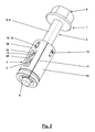
- zeigt die erste Ausführungsform des neuen Verbindungselements in perspektivischer Darstellung.
- Fig. 3
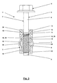
- zeigt eine zweite Ausführungsform des neuen Verbindungselements.
- Fig. 4
- zeigt die erste Ausführungsform des neuen Verbindungselements mit maximal in die Hülse eingeschobener Schraube.
- Fig. 5
- zeigt die erste Ausführungsform des neuen Verbindungselements in einer ersten Stellung während der Vormontage an einem Bauteil.
- Fig. 6
- zeigt die erste Ausführungsform des neuen Verbindungselements in einer zweiten Stellung während der Vormontage an einem Bauteil.
- Fig. 7
- zeigt die erste Ausführungsform des neuen Verbindungselements in einer dritten Stellung während der Vormontage an einem Bauteil.
- Fig. 8
- zeigt die erste Ausführungsform des neuen Verbindungselements in einer vierten Stellung während der Vormontage an einem Bauteil.
- Fig. 9
- zeigt die erste Ausführungsform des neuen Verbindungselements während der Endmontage.
- Fig. 10
- zeigt die zweite Ausführungsform des neuen Verbindungselements während der Endmontage.
- Fig. 11
- zeigt eine dritte Ausführungsform des neuen Verbindungselements.
- Fig. 12
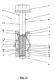
- zeigt eine vierte Ausführungsform des neuen Verbindungselements.
- Fig. 13
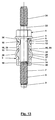
- zeigt eine fünfte Ausführungsform des neuen Verbindungselements.
- Fig. 14
- zeigt eine sechste Ausführungsform des neuen Verbindungselements.
- Fig. 1
- shows a first embodiment of the new connecting element.
- Fig. 2
- shows the first embodiment of the new connecting element in a perspective view.
- Fig. 3
- shows a second embodiment of the new connecting element.
- Fig. 4
- shows the first embodiment of the new connecting element with maximum inserted into the sleeve screw.
- Fig. 5
- shows the first embodiment of the new connecting element in a first position during the pre-assembly of a component.
- Fig. 6
- shows the first embodiment of the new connecting element in a second position during the pre-assembly of a component.
- Fig. 7
- shows the first embodiment of the new connecting element in a third position during the pre-assembly of a component.
- Fig. 8
- shows the first embodiment of the new connecting element in a fourth position during the pre-assembly of a component.
- Fig. 9
- shows the first embodiment of the new connector during final assembly.
- Fig. 10
- shows the second embodiment of the new connecting element during final assembly.
- Fig. 11
- shows a third embodiment of the new connecting element.
- Fig. 12
- shows a fourth embodiment of the new connecting element.
- Fig. 13
- shows a fifth embodiment of the new connecting element.
- Fig. 14
- shows a sixth embodiment of the new connecting element.
Die Hülse 3 ist im Wesentlichen kreisringförmig ausgebildet. Sie ist vorzugsweise aus einem ebenen Blechabschnitt geformt, aus dem dann die Hülse 3 durch Rollen geformt wird. Genauer gesagt entsteht nach dem Rollen des Blechstreifens eine Rohhülse mit einem Innendurchmesser, der noch größer ist als der Außendurchmesser des Gewindes 8, so dass bei der Herstellung des Verbindungselements 1 die Schraube 2 in die Hülse 3 eingeführt werden kann. Anschließend erfolgt ein Quetschvorgang in radialer Richtung, unter dem sich der Innendurchmesser der Hülse 3 verkleinert. Dies kann im Bereich des Schaftabschnitts 6 geschehen, ist aber auch in der Relativlage möglich, die
Die Hülse 3 ist in besonderer Weise ausgebildet. Die Hülse 3 weist eine erste Engstelle 10 auf. Die erste Engstelle 10 weist mehrere über den Umfang der Hülse 3 verteilt angeordnete Einprägungen 12 auf, die radial nach innen vorstehende Vorsprünge bilden. Es können beispielsweise eine, zwei, drei oder vier Einprägungen 12 auf dem Umfang gleichmäßig verteilt vorgesehen sein. Im vorliegenden bevorzugten Beispiel sind vier Einprägungen 12 vorhanden. Die Einprägungen 12 können auf ihrer nach innen vorspringenden Seite Flächenelemente 13 bilden, die sich zu einer kegelförmigen Umhüllung des kopfseitigen Gewindeauslaufs 14 des Gewindeabschnitts 7 ergänzen, wie dies in der
Weiterhin sind zwei federnd-nachgiebig ausgebildete Elemente 15 vorgesehen, die ebenfalls über den Umfang der Hülse 3 verteilt angeordnet sind. Es können aber auch mehr oder weniger federnde Elemente 15 vorhanden sein. Diese federnden Elemente 15 bilden später die zweite Engstelle 11, wie dies weiter unterhalb beschrieben wird. Die federnden Elemente 15 können zungenartig aus dem Material der Hülse 3 angeschnitten bzw. ausgeformt sein. Ihre freien Enden 16 sind hier scharfkantig bzw. widerhakenartig ausgebildet. Die federnden Elemente 15 weisen jeweils einen Betätigungsbereich 28 und einen Eingriffsbereich 29 auf, wobei in einer gezeigten unmontierten Stellung des Verbindungselements 1 der Betätigungsbereich 28 derart radial aus der äußeren Umfangsfläche 30 der Hülse 3 heraussteht, dass der Eingriffsbereich 29 nicht in das Gewinde 8 des Gewindeabschnitts 7 eingreift. Die federnden Elemente 15 sind also noch nicht aktiv und bilden noch keine zweite Engstelle 11.Furthermore, two resiliently designed
Es versteht sich, dass die Ausbildung der Elemente für die erste Engstelle 10 und für die zweite Engstelle 11 vorteilhaft durch Stanz- bzw. Drückvorgänge am noch ebenen Blechstreifen realisiert werden können, also in einer Stellung, in der mit Gegenlagern gearbeitet werden kann, so dass die Anordnung und Dimensionierung der Elemente für die erste und zweite Engstelle 10, 11 in engen Toleranzen einhaltbar ist. Das Wickeln der Rohhülse aus dem ebenen Blechstreifen geschieht dann so, dass zwischen den einander zugekehrten Enden des Blechstreifens ein Spalt entsteht und die inneren Enden der Einprägungen 12 und der federnden Elemente 15 auf Durchmessern liegen, die größer als der Außendurchmesser des Gewindes 8 des Gewindeabschnitts 7 bemessen sind. In dieser Stellung werden also Schraube 2 und Hülse 3 ineinandergeschoben und einem Quetschvorgang ausgesetzt, wobei der Spalt an der Hülse 3 zu einem Schlitz 17 zusammengedrückt werden kann. Dabei werden die Einprägungen 12 auf einen Durchmesser gebracht, der den Außendurchmesser des Gewindes 8 des Gewindeabschnitts 7 unterschreitet, während der Durchmesser der federnden Elemente 15 größer ist. Wenn der Quetschvorgang unter Relativlage der Rohhülse gegenüber dem Schaftabschnitt 6 geschieht, ist es anschließend möglich, die Schraube 2 aus der Hülse 3 teilweise herauszudrücken, bis die Einprägungen 12 der ersten Engstelle an dem Gewindeauslauf 14 zur Anlage kommen. In dieser Stellung, die in
Die Hülse 3 kann hinsichtlich der Ausbildung der ersten Engstelle 10 und/oder der zweiten Engstelle 11 so getroffen sein, dass die Formgebung dieser Elemente 10, 11 zugleich ein Merkmal der Hülse 3 darstellt, welches eine automatische Erkennung der Orientierung der Hülse 3 in einer automatisch arbeitenden Montagemaschine zur unverlierbaren Verbindung zwischen Schraube 2 und Hülse 3 ermöglicht. Andererseits ist es auch möglich, die Hülse 3 mit einer insbesondere nach innen vorspringenden Wulst 18 auszustatten, so dass dieses Merkmal zur automatischen Erkennung der Orientierung der Hülse herangezogen werden kann. Es versteht sich, dass der Innendurchmesser der Wulst 18 immer noch erheblich größer als der Außendurchmesser des Gewindes 8 gestaltet ist, so dass die Wulst 18 das ordnungsgemäße Zusammenarbeiten der Engstellen 10 und 11 nicht beeinträchtigt.The
Die Länge der Hülse 3 kann größer als die Länge des Gewindeabschnitts 7 ausgebildet sein.
Bei der in
Wie
Die federnden Elemente 15 sind mit ihren freien Enden 16 der zweiten Engstelle 11 vorzugsweise so ausgebildet, angeordnet und bemessen, dass die freien Enden 16 steigungsbehaftet enden, so dass sie mehr oder weniger gleichzeitig über den Umfang gesehen in die Vertiefung des Gewindes 8 des Gewindeabschnitts 7 eintreten können. Diese Ausbildung und Anpassung kann sogar dazu genutzt werden, um anschließend an eine Axialbewegung der Schraube 2 gegenüber der Hülse 3 bei der Montage des Verbindungselements 1 noch eine geringfügige Relativverdrehung zwischen Schraube 2 und Hülse 3 herbeizuführen, um die begrenzte axiale Beweglichkeit gänzlich zu beseitigen und die Schraube 2 und die Hülse 3 gleichsam fest bzw. zu einem festen Verbindungselement 1 zusammenzufügen.The
Die weitere Endmontage an einem zweiten Bauteil 23 ist anhand von
Es ist in den Figuren auch erkennbar, dass die nach innen vorspringende Wulst 18 auf der Außenseite der Hülse 3 eine umlaufende Nut bildet, die nicht nur zur Erkennung der Orientierung bei der Herstellung des Verbindungselements 1 genutzt werden kann, sondern die als Durchgangsloch ausgebildete Bohrung 22 in axialer Zuordnung zu der umlaufenden Nut der Wulst 18 einen umlaufenden Vorsprung 27 (nicht dargestellt) aufweisen kann, so dass damit die axiale Lage der Hülse 3 und des Verbindungselements 1 im Bauteil 20 bestimmt wird. In Verbindung mit der Darstellung und Anordnung der beiden Engstellen 10 und 11 zueinander ist erkennbar, dass die Ausbildung und Abstimmung aufeinander so getroffen werden kann, dass die Reihenfolge des Freikommens des Gewindeabschnitts 7 von der zweiten Engstelle 11 während der Endmontage festgelegt werden kann. So kann die Ausbildung und Abstimmung z. B. so getroffen sein, dass der Gewindeabschnitt 7 von der zweiten Engstelle 11 freikommt, bevor der erste Gewindegang des Gewindes 8 Kontakt zu dem Gewinde im Gewindeloch 25 des anderen Bauteils 23 bekommen hat. Wenn die federnden Elemente 15 mit abgerundeten freien Enden 16 ausgestattet sind, kann auch eine Überschneidung des Austretens des Gewindeabschnitts 7 aus der zweiten Engstelle und ein Eintreten in den Gewindegang des Gewindelochs 25 in Überlappung realisiert werden. Es kann durchaus sinnvoll sein, diese Überlappung durchzuführen.It can also be seen in the figures that the inwardly projecting
Elemente der beiden Engstellen 10 und 11 sind hier zusammengefasst. Die Einprägungen 12 sind hier gleichzeitig auch als federnde Elemente 15 ausgebildet, wobei sie einerseits in einem nicht federnden Bereich die Flächenelemente 13 bilden und andererseits im freien Endbereich die freien Enden 16 der federnden Elemente 15 darstellen. Es versteht sich, dass die Abstimmung aufeinander entsprechend sorgfältig dimensioniert und ausgebildet ist. Die freien Enden 16 sind nicht steigungsbehaftet angeordnet, also in axialer Richtung auf einer gemeinsamen Umfangslinie bzw. -ebene liegen. Die freien Enden 16 der federnden Elemente 15 können in der dargestellten Weise mit unterschiedlich wirkenden Schrägflächen versehen sein, so dass ein Überschnappen über die Spitzen der Gewindegänge des Gewindes 8 nur in der einen Richtung möglich ist.Elements of the two
- 11
- Verbindungselementconnecting element
- 22
- Schraubescrew
- 33
- Hülseshell
- 44
- Kopfhead
- 55
- Schaftshaft
- 66
- Schaftabschnittshank portion
- 77
- Gewindeabschnittthreaded portion
- 88th
- Gewindethread
- 99
- ZentrieransatzSpigot
- 1010
- erste Engstellefirst bottleneck
- 1111
- zweite Engstellesecond bottleneck
- 1212
- Einprägungimpressing
- 1313
- Flächenelementsurface element
- 1414
- Gewindeauslaufthread run
- 1515
- federndes Elementresilient element
- 1616
- freies Endefree end
- 1717
- Schlitzslot
- 1818
- Wulstbead
- 1919
- Spaltgap
- 2020
- Bauteilcomponent
- 2121
- vormontierte Baueinheitpreassembled unit
- 2222
- Bohrungdrilling
- 2323
- Bauteilcomponent
- 2424
- Dichtungpoetry
- 2525
- Gewindelochthreaded hole
- 2626
- Fasechamfer
- 2727
- Vorsprunghead Start
- 2828
- Betätigungsbereichoperating range
- 2929
- Eingriffsbereichengagement area
- 3030
- äußere Umfangsflächeouter peripheral surface
- 3131
- Freiraumfree space
- 3232
- Unterlegscheibewasher
- 3333
- Schaftabschnittshank portion
- 3434
- Gewindeabschnittthreaded portion
Claims (12)
einer Schraube (2),
wobei die Schraube (2) einen Kopf (4), einen Schaftabschnitt (6) und einen Gewindeabschnitt (7) mit einem Gewinde (8) aufweist,
wobei der Schaftabschnitt (6) dem Kopf (4) zugekehrt und der Gewindeabschnitt (7) von dem Kopf (4) abgekehrt angeordnet ist,
wobei der Schaftabschnitt (6) einen Durchmesser besitzt, der kleiner als der Außendurchmesser des Gewindes (8) des Gewindeabschnitts (7) ist; und einer Hülse (3),
wobei die Hülse (3) eine erste Engstelle (10) mit einem Durchmesser besitzt, der kleiner als der Außendurchmesser des Gewindes (8) des Gewindeabschnitts (7) ist,
dadurch gekennzeichnet, dass
die Hülse (3) ein federndes Element (15) mit einem Betätigungsbereich (28) und einem Eingriffsbereich (29) aufweist,
wobei in einer unmontierten Stellung des Verbindungselements (1) der Betätigungsbereich (28) derart aus der äußeren Umfangsfläche der Hülse (3) heraussteht, dass der Eingriffsbereich (29) nicht in das Gewinde (8) des Gewindeabschnitts (7) eingreift, und
wobei in einer vormontierten Stellung des Verbindungselements (1) in einer Bohrung (22) eines Bauteils (20) der Betätigungsbereich (28) derart nach innen gedrückt ist, dass der Eingriffsbereich (29) in das Gewinde (8) des Gewindeabschnitts (7) eingreift.Connecting element (1), with
a screw (2),
the screw (2) having a head (4), a shank portion (6) and a threaded portion (7) with a thread (8),
wherein the shaft portion (6) facing the head (4) and the threaded portion (7) facing away from the head (4),
the shank portion (6) having a diameter smaller than the outer diameter of the thread (8) of the threaded portion (7); and a sleeve (3),
the sleeve (3) having a first throat (10) with a diameter smaller than the outside diameter of the thread (8) of the threaded portion (7),
characterized in that
the sleeve (3) has a resilient element (15) with an actuating region (28) and an engagement region (29),
wherein in an unmounted position of the connecting member (1), the operating portion (28) protrudes from the outer peripheral surface of the sleeve (3) such that the engaging portion (29) does not engage the thread (8) of the threaded portion (7);
wherein in a preassembled position of the connecting element (1) in a bore (22) of a component (20) of the actuating portion (28) is pressed inwardly such that the engagement portion (29) engages in the thread (8) of the threaded portion (7) ,
in der unmontierten Stellung des Verbindungselements (1) radial aus der äußeren Umfangsfläche der Hülse (3) heraussteht, und
in der vormontierten Stellung des Verbindungselements (1) in der Bohrung (22) des Bauteils (20) radial nach innen gedrückt ist.Connecting element (1) according to at least one of claims 1 to 7, characterized in that the actuating region (28) of the resilient element (15)
in the unmounted position of the connecting element (1) protrudes radially out of the outer peripheral surface of the sleeve (3), and
in the preassembled position of the connecting element (1) in the bore (22) of the component (20) is pressed radially inwardly.
einem Bauteil (20) mit einer Bohrung (22); und
einem Verbindungselement (1), insbesondere einem Verbindungselement (1) nach mindestens einem der Ansprüche 1 bis 9, mit
einer Schraube (2),
wobei die Schraube (2) einen Kopf (4), einen Schaftabschnitt (6) und einen Gewindeabschnitt (7) mit einem Gewinde (8) aufweist,
wobei der Schaftabschnitt (6) dem Kopf (4) zugekehrt und der Gewindeabschnitt (7) von dem Kopf (4) abgekehrt angeordnet ist,
wobei der Schaftabschnitt (6) einen Durchmesser besitzt, der kleiner als der Außendurchmesser des Gewindes (8) des Gewindeabschnitts (7) ist, und einer Hülse (3),
wobei die Hülse (3) eine erste Engstelle (10) mit einem Durchmesser besitzt, der kleiner als der Außendurchmesser des Gewindes (8) des Gewindeabschnitts (7) ist, dadurch gekennzeichnet, dass
die Hülse (3) ein federndes Element (15) mit einem Betätigungsbereich (28) und einem Eingriffsbereich (29) aufweist,
wobei in einer unmontierten Stellung des Verbindungselements (1) der Betätigungsbereich (28) derart aus der äußeren Umfangsfläche der Hülse (3) heraussteht, dass der Eingriffsbereich (29) nicht in das Gewinde (8) des Gewindeabschnitts (7) eingreift, und
wobei in einer vormontierten Stellung des Verbindungselements (1) in der Bohrung (22) des Bauteils (20) der Betätigungsbereich (28) derart nach innen gedrückt ist, dass der Eingriffsbereich (29) in das Gewinde (8) des Gewindeabschnitts (7) eingreift.Pre-assembled unit (21), with
a component (20) having a bore (22); and
a connecting element (1), in particular a connecting element (1) according to at least one of claims 1 to 9, with
a screw (2),
the screw (2) having a head (4), a shank portion (6) and a threaded portion (7) with a thread (8),
wherein the shaft portion (6) facing the head (4) and the threaded portion (7) facing away from the head (4),
the shank portion (6) having a diameter smaller than the outer diameter of the thread (8) of the threaded portion (7) and a sleeve (3),
the sleeve (3) having a first constriction (10) with a diameter smaller than the outside diameter of the thread (8) of the threaded portion (7), characterized in that
the sleeve (3) has a resilient element (15) with an actuating region (28) and an engagement region (29),
wherein in an unmounted position of the connecting member (1), the operating portion (28) protrudes from the outer peripheral surface of the sleeve (3) such that the engaging portion (29) does not engage the thread (8) of the threaded portion (7);
wherein in a preassembled position of the connecting element (1) in the bore (22) of the component (20) the actuating portion (28) is pressed inwardly such that the engaging portion (29) engages the thread (8) of the threaded portion (7) ,
die erste Engstelle (10) einen Durchmesser besitzt, der kleiner als der Außendurchmesser des Gewindes (8) des Gewindeabschnitts (7) ist, so dass die Schraube (2) und die Hülse (3) unverlierbar miteinander verbunden sind, und
in einer unmontierten Stellung des Verbindungselements (1) ein Betätigungsbereich (28) des federnden Elements (15) derart aus der äußeren Umfangsfläche der Hülse (3) heraussteht, dass ein Eingriffsbereich (29) des federnden Elements (15) nicht in das Gewinde (8) des Gewindeabschnitts (7) eingreift, und
in einer vormontierten Stellung des Verbindungselements (1) in einer Bohrung (22) eines Bauteils (20) der Betätigungsbereich (28) derart nach innen gedrückt ist, dass der Eingriffsbereich (29) in das Gewinde (8) des Gewindeabschnitts (7) eingreift und somit die zweite Engstelle (11) bildet.
the first constriction (10) has a diameter which is smaller than the outer diameter of the thread (8) of the threaded portion (7), so that the screw (2) and the sleeve (3) are captively connected, and
In an unmounted position of the connecting element (1), an actuating region (28) of the resilient element (15) projects out of the outer peripheral surface of the sleeve (3) such that an engagement region (29) of the resilient element (15) does not protrude into the thread (8 ) engages the threaded portion (7), and
in a preassembled position of the connecting element (1) in a bore (22) of a component (20) of the actuating portion (28) is pressed inwardly such that the engagement portion (29) engages in the thread (8) of the threaded portion (7) and thus forms the second bottleneck (11).
der Materialstreifen unter Bildung eines Spalts mit einem ersten Durchmesser zu der Rohhülse gerollt wird, und
die Rohhülse durch den Quetschvorgang zu der Hülse (3) mit einem Schlitz (17) oder einem Spalt (19) mit einem zweiten Durchmesser verformt wird, der kleiner als der erste Durchmesser ist.A method according to claim 11, characterized in that
the material strip is rolled to form a gap having a first diameter to the green sleeve, and
the green sleeve is deformed by the squeezing operation to the sleeve (3) with a slot (17) or a gap (19) having a second diameter which is smaller than the first diameter.
Applications Claiming Priority (1)
| Application Number | Priority Date | Filing Date | Title |
|---|---|---|---|
| DE102008029236A DE102008029236B3 (en) | 2008-06-19 | 2008-06-19 | Connecting element with a screw and a captive arranged sleeve |
Publications (3)
| Publication Number | Publication Date |
|---|---|
| EP2136088A2 true EP2136088A2 (en) | 2009-12-23 |
| EP2136088A3 EP2136088A3 (en) | 2012-01-04 |
| EP2136088B1 EP2136088B1 (en) | 2014-08-20 |
Family
ID=41012078
Family Applications (1)
| Application Number | Title | Priority Date | Filing Date |
|---|---|---|---|
| EP09162495.7A Active EP2136088B1 (en) | 2008-06-19 | 2009-06-11 | Connection element with a screw and an undetachable attached casing |
Country Status (5)
| Country | Link |
|---|---|
| US (1) | US8210784B2 (en) |
| EP (1) | EP2136088B1 (en) |
| JP (1) | JP5527505B2 (en) |
| DE (1) | DE102008029236B3 (en) |
| ES (1) | ES2522915T3 (en) |
Cited By (2)
| Publication number | Priority date | Publication date | Assignee | Title |
|---|---|---|---|---|
| DE102016101692A1 (en) | 2016-02-01 | 2017-08-03 | Heismann Drehtechnik Gmbh & Co. Kg | Connecting device, device and method for this purpose |
| WO2019091945A1 (en) * | 2017-11-07 | 2019-05-16 | Arnold Umformtechnik Gmbh & Co. Kg | Securing means for screws, and mounting unit |
Families Citing this family (19)
| Publication number | Priority date | Publication date | Assignee | Title |
|---|---|---|---|---|
| WO2008070536A2 (en) | 2006-12-05 | 2008-06-12 | Illinois Tool Works Inc. | Bushing assembly |
| CA2786789C (en) * | 2010-02-12 | 2016-10-25 | Hilti Aktiengesellschaft | Method of forming anchor bolts |
| EP2511539A1 (en) * | 2011-04-11 | 2012-10-17 | Amec System GmbH | Screw connection |
| US10550876B2 (en) | 2011-12-05 | 2020-02-04 | Acument Intellectual Properties, Llc | Fastener with attached compression limiting sleeve |
| US11371544B2 (en) | 2011-12-05 | 2022-06-28 | Acument Intellectual Properties, Llc | Fastener with attached compression limiting sleeve |
| DE102014000940A1 (en) * | 2014-01-23 | 2015-07-23 | Sfs Intec Holding Ag | Screw, mounting arrangement and use of a screw |
| EP3120033B1 (en) * | 2014-03-19 | 2022-04-13 | Penn Engineering & Manufacturing Corp. | Stabilized panel fastener |
| DE102016116882A1 (en) * | 2015-09-23 | 2017-03-23 | Richard Bergner Verbindungstechnik Gmbh & Co. Kg | Assembly unit with a mounting part and a sleeve fixed therein |
| FR3064035B1 (en) * | 2017-03-16 | 2019-04-19 | Sogefi Air & Cooling | REMOVABLE SLEEVE FOR HOLDING AND ATTACHING SCREWS |
| US20190383315A1 (en) * | 2018-06-18 | 2019-12-19 | General Fasteners Company | Compression limiter fastener assembly |
| US11808034B2 (en) * | 2019-03-08 | 2023-11-07 | Omg, Inc. | Floating connection fastening system |
| US11319983B2 (en) * | 2019-12-14 | 2022-05-03 | ECO Holding 1 GmbH | Arrangement for introducing a force from a fastening element into a plastic component and method for producing the arrangement |
| USD952450S1 (en) * | 2020-02-03 | 2022-05-24 | Wheel Pros, Llc | Bolt |
| USD918700S1 (en) * | 2020-02-03 | 2021-05-11 | Wheel Pros, Llc | Bolt |
| USD918701S1 (en) * | 2020-02-03 | 2021-05-11 | Wheel Pros, Llc | Bolt |
| US11566655B2 (en) * | 2020-02-20 | 2023-01-31 | Caterpillar Inc. | Bolt retainer configuration to hold a position of a bolt within a component |
| US20220074445A1 (en) * | 2020-09-08 | 2022-03-10 | Apq Development, Llc | Fastener Retainer |
| CN216241731U (en) * | 2021-07-29 | 2022-04-08 | 浙江印天健康科技有限公司 | Fastening screw and lifting table using same |
| FR3128256A1 (en) | 2021-10-15 | 2023-04-21 | A. Raymond Et Cie | Fixing device |
Citations (4)
| Publication number | Priority date | Publication date | Assignee | Title |
|---|---|---|---|---|
| US5489177A (en) | 1994-06-08 | 1996-02-06 | Crest Products, Inc. | Fastener assembly with axially captivated washer |
| DE19924502A1 (en) | 1999-05-28 | 2000-12-21 | Elringklinger Gmbh | Screw with sleeve |
| DE10215883A1 (en) | 2002-04-11 | 2003-10-30 | Kellermann Fa Rudolf | Connecting element with a screw and a support element arranged captively thereon |
| DE102005002603A1 (en) | 2004-01-20 | 2005-10-20 | Bergner Verbindungstechnik Gmb | Mounting and fastening unit, has mounting part, fixed at base construction, with passage opening, fasteners clamp down on opening, and holding units whose axial positions are selected such that fixing section is arranged in opening |
Family Cites Families (12)
| Publication number | Priority date | Publication date | Assignee | Title |
|---|---|---|---|---|
| US1328488A (en) * | 1919-03-22 | 1920-01-20 | Junius A Bowden | Dust-cap and attaching means therefor |
| US2972367A (en) * | 1957-07-18 | 1961-02-21 | United Carr Fastener Corp | Fastening device |
| NL244886A (en) * | 1958-11-07 | |||
| US3525285A (en) * | 1968-10-08 | 1970-08-25 | Tinnerman Products Inc | Fastening assembly device |
| US4311422A (en) * | 1980-05-19 | 1982-01-19 | Midland-Ross Corporation | Screw retainer |
| JPS602334Y2 (en) * | 1980-07-15 | 1985-01-23 | 株式会社ニフコ | Natsuto |
| DE4226346A1 (en) * | 1992-08-08 | 1994-02-10 | Philips Patentverwaltung | Circuit arrangement for determining the field strength of FM transmitters |
| DE332604C (en) * | 2000-03-11 | 1921-07-09 | Bruno Schwarze Dr | Wardrobe for hospitals, clinics, factories, etc. |
| IT1319607B1 (en) * | 2000-12-21 | 2003-10-20 | C V B S R L | PROCEDURE FOR THE PRODUCTION OF THREADED CONNECTION UNIT WITH HIGH-SAFETY ANTI-REMOVAL BUSHING |
| US6585468B2 (en) * | 2001-02-02 | 2003-07-01 | H. Thad Johnson | Captivated fastener assembly with post-formed retention feature and method for forming the same |
| DE10106093C2 (en) * | 2001-02-08 | 2003-03-20 | Kellermann Fa Rudolf | Connecting element with a screw and a support element arranged captively thereon |
| JP2008095928A (en) * | 2006-10-16 | 2008-04-24 | Misako Sato | Fastening member |
-
2008
- 2008-06-19 DE DE102008029236A patent/DE102008029236B3/en not_active Expired - Fee Related
-
2009
- 2009-06-11 US US12/482,754 patent/US8210784B2/en active Active
- 2009-06-11 EP EP09162495.7A patent/EP2136088B1/en active Active
- 2009-06-11 ES ES09162495.7T patent/ES2522915T3/en active Active
- 2009-06-17 JP JP2009144625A patent/JP5527505B2/en not_active Expired - Fee Related
Patent Citations (5)
| Publication number | Priority date | Publication date | Assignee | Title |
|---|---|---|---|---|
| US5489177A (en) | 1994-06-08 | 1996-02-06 | Crest Products, Inc. | Fastener assembly with axially captivated washer |
| DE19924502A1 (en) | 1999-05-28 | 2000-12-21 | Elringklinger Gmbh | Screw with sleeve |
| EP1055829B1 (en) | 1999-05-28 | 2007-01-17 | Elring Klinger AG | Screw with sleeve |
| DE10215883A1 (en) | 2002-04-11 | 2003-10-30 | Kellermann Fa Rudolf | Connecting element with a screw and a support element arranged captively thereon |
| DE102005002603A1 (en) | 2004-01-20 | 2005-10-20 | Bergner Verbindungstechnik Gmb | Mounting and fastening unit, has mounting part, fixed at base construction, with passage opening, fasteners clamp down on opening, and holding units whose axial positions are selected such that fixing section is arranged in opening |
Cited By (5)
| Publication number | Priority date | Publication date | Assignee | Title |
|---|---|---|---|---|
| DE102016101692A1 (en) | 2016-02-01 | 2017-08-03 | Heismann Drehtechnik Gmbh & Co. Kg | Connecting device, device and method for this purpose |
| WO2019091945A1 (en) * | 2017-11-07 | 2019-05-16 | Arnold Umformtechnik Gmbh & Co. Kg | Securing means for screws, and mounting unit |
| CN111566362A (en) * | 2017-11-07 | 2020-08-21 | 阿诺德成形技术有限责任两合公司 | Anti-loss device for bolt and assembly unit |
| CN111566362B (en) * | 2017-11-07 | 2022-04-29 | 阿诺德成形技术有限责任两合公司 | Anti-loss device for bolt and assembly unit |
| US11473612B2 (en) | 2017-11-07 | 2022-10-18 | Arnold Umformtechnik Gmbh & Co. Kg | Securing means for screws, and mounting unit |
Also Published As
| Publication number | Publication date |
|---|---|
| US20090317207A1 (en) | 2009-12-24 |
| US8210784B2 (en) | 2012-07-03 |
| JP5527505B2 (en) | 2014-06-18 |
| EP2136088B1 (en) | 2014-08-20 |
| EP2136088A3 (en) | 2012-01-04 |
| ES2522915T3 (en) | 2014-11-19 |
| JP2010032042A (en) | 2010-02-12 |
| DE102008029236B3 (en) | 2010-02-11 |
Similar Documents
| Publication | Publication Date | Title |
|---|---|---|
| EP2136088B1 (en) | Connection element with a screw and an undetachable attached casing | |
| EP2063136B1 (en) | Fastening element with attachable captive washer sleeve | |
| EP2047125B1 (en) | Sleeve | |
| EP0667936B1 (en) | Method of fabricating a compound part being secure against rotation and insert ejection by pressing an insert into a sheet metal and inserts usable therefore | |
| EP1979634B1 (en) | Mounting unit for the fastening eyelet of a belt buckle | |
| DE112008004188B4 (en) | Fixing structure with a grommet | |
| EP1419319B1 (en) | Self-piercing fixing element that can be press-fitted to sheet metal in a torsion and expulsion-proof manner | |
| EP2047127B1 (en) | Combination of a screw, a washer and a sleeve and method for producing said combination | |
| DE102012221228A1 (en) | Device for compensating tolerances between two screwed components, has spacer ring that acts in axial direction and is moved to component against restoring force of fastener fixedly connected to base element | |
| EP1205676B1 (en) | Assembly unit consisting of a component and at least one screw | |
| DE60303724T2 (en) | Spring unit and manufacturing method for it | |
| EP1456544B1 (en) | Ball-and-socket joint | |
| EP2082144A1 (en) | Combination of a screw and a sleeve, and method for producing a combination of this type | |
| EP1591676B1 (en) | Clinch nut | |
| DE10020218B4 (en) | Assembly unit of a component and at least one thread-forming screw | |
| DE10254999B4 (en) | assembly unit | |
| EP3956572B1 (en) | Connection unit and method for producing a connection unit | |
| EP3615265A1 (en) | Press-in connecting element and method for anchoring press-in connecting elements in a permanently deformable flat metal material or components or workpieces produced therefrom | |
| EP2382397B1 (en) | Multipart screw element, screw connection, and method for producing a multipart screw element | |
| DE102012013243A1 (en) | Shaft assembly i.e. cam shaft assembly, has locking ring for engaging shaft recess and component recess, and slot formed in shaft recess, so that base of shaft recess comprises non-circular part that is provided in cross-section | |
| EP3473871B1 (en) | Method for setting a blind rivet element for stiffening two separated sections of two components or a component | |
| DE102010001027B4 (en) | assembly unit | |
| EP0724109B1 (en) | Plug connector for high-pressure fluid lines | |
| DE10107581B4 (en) | Device for connecting a plastic part to a flat carrier part | |
| DE102008063692A1 (en) | Method and device for producing a thread and component and device |
Legal Events
| Date | Code | Title | Description |
|---|---|---|---|
| PUAI | Public reference made under article 153(3) epc to a published international application that has entered the european phase |
Free format text: ORIGINAL CODE: 0009012 |
|
| AK | Designated contracting states |
Kind code of ref document: A2 Designated state(s): AT BE BG CH CY CZ DE DK EE ES FI FR GB GR HR HU IE IS IT LI LT LU LV MC MK MT NL NO PL PT RO SE SI SK TR |
|
| PUAL | Search report despatched |
Free format text: ORIGINAL CODE: 0009013 |
|
| AK | Designated contracting states |
Kind code of ref document: A3 Designated state(s): AT BE BG CH CY CZ DE DK EE ES FI FR GB GR HR HU IE IS IT LI LT LU LV MC MK MT NL NO PL PT RO SE SI SK TR |
|
| AX | Request for extension of the european patent |
Extension state: AL BA RS |
|
| RIC1 | Information provided on ipc code assigned before grant |
Ipc: F16B 37/14 20060101AFI20111130BHEP |
|
| RAP1 | Party data changed (applicant data changed or rights of an application transferred) |
Owner name: KAMAX HOLDING GMBH & CO. KG |
|
| 17P | Request for examination filed |
Effective date: 20120608 |
|
| GRAP | Despatch of communication of intention to grant a patent |
Free format text: ORIGINAL CODE: EPIDOSNIGR1 |
|
| 17Q | First examination report despatched |
Effective date: 20121019 |
|
| GRAP | Despatch of communication of intention to grant a patent |
Free format text: ORIGINAL CODE: EPIDOSNIGR1 |
|
| INTG | Intention to grant announced |
Effective date: 20140513 |
|
| GRAS | Grant fee paid |
Free format text: ORIGINAL CODE: EPIDOSNIGR3 |
|
| GRAA | (expected) grant |
Free format text: ORIGINAL CODE: 0009210 |
|
| AK | Designated contracting states |
Kind code of ref document: B1 Designated state(s): AT BE BG CH CY CZ DE DK EE ES FI FR GB GR HR HU IE IS IT LI LT LU LV MC MK MT NL NO PL PT RO SE SI SK TR |
|
| REG | Reference to a national code |
Ref country code: GB Ref legal event code: FG4D Free format text: NOT ENGLISH |
|
| REG | Reference to a national code |
Ref country code: CH Ref legal event code: EP |
|
| REG | Reference to a national code |
Ref country code: AT Ref legal event code: REF Ref document number: 683634 Country of ref document: AT Kind code of ref document: T Effective date: 20140915 |
|
| REG | Reference to a national code |
Ref country code: IE Ref legal event code: FG4D Free format text: LANGUAGE OF EP DOCUMENT: GERMAN |
|
| REG | Reference to a national code |
Ref country code: DE Ref legal event code: R096 Ref document number: 502009009819 Country of ref document: DE Effective date: 20141002 |
|
| REG | Reference to a national code |
Ref country code: SE Ref legal event code: TRGR |
|
| REG | Reference to a national code |
Ref country code: ES Ref legal event code: FG2A Ref document number: 2522915 Country of ref document: ES Kind code of ref document: T3 Effective date: 20141119 |
|
| REG | Reference to a national code |
Ref country code: NL Ref legal event code: T3 |
|
| REG | Reference to a national code |
Ref country code: LT Ref legal event code: MG4D |
|
| PG25 | Lapsed in a contracting state [announced via postgrant information from national office to epo] |
Ref country code: FI Free format text: LAPSE BECAUSE OF FAILURE TO SUBMIT A TRANSLATION OF THE DESCRIPTION OR TO PAY THE FEE WITHIN THE PRESCRIBED TIME-LIMIT Effective date: 20140820 Ref country code: GR Free format text: LAPSE BECAUSE OF FAILURE TO SUBMIT A TRANSLATION OF THE DESCRIPTION OR TO PAY THE FEE WITHIN THE PRESCRIBED TIME-LIMIT Effective date: 20141121 Ref country code: BG Free format text: LAPSE BECAUSE OF FAILURE TO SUBMIT A TRANSLATION OF THE DESCRIPTION OR TO PAY THE FEE WITHIN THE PRESCRIBED TIME-LIMIT Effective date: 20141120 Ref country code: NO Free format text: LAPSE BECAUSE OF FAILURE TO SUBMIT A TRANSLATION OF THE DESCRIPTION OR TO PAY THE FEE WITHIN THE PRESCRIBED TIME-LIMIT Effective date: 20141120 Ref country code: LT Free format text: LAPSE BECAUSE OF FAILURE TO SUBMIT A TRANSLATION OF THE DESCRIPTION OR TO PAY THE FEE WITHIN THE PRESCRIBED TIME-LIMIT Effective date: 20140820 Ref country code: PT Free format text: LAPSE BECAUSE OF FAILURE TO SUBMIT A TRANSLATION OF THE DESCRIPTION OR TO PAY THE FEE WITHIN THE PRESCRIBED TIME-LIMIT Effective date: 20141222 |
|
| PG25 | Lapsed in a contracting state [announced via postgrant information from national office to epo] |
Ref country code: HR Free format text: LAPSE BECAUSE OF FAILURE TO SUBMIT A TRANSLATION OF THE DESCRIPTION OR TO PAY THE FEE WITHIN THE PRESCRIBED TIME-LIMIT Effective date: 20140820 Ref country code: LV Free format text: LAPSE BECAUSE OF FAILURE TO SUBMIT A TRANSLATION OF THE DESCRIPTION OR TO PAY THE FEE WITHIN THE PRESCRIBED TIME-LIMIT Effective date: 20140820 Ref country code: IS Free format text: LAPSE BECAUSE OF FAILURE TO SUBMIT A TRANSLATION OF THE DESCRIPTION OR TO PAY THE FEE WITHIN THE PRESCRIBED TIME-LIMIT Effective date: 20141220 |
|
| PG25 | Lapsed in a contracting state [announced via postgrant information from national office to epo] |
Ref country code: EE Free format text: LAPSE BECAUSE OF FAILURE TO SUBMIT A TRANSLATION OF THE DESCRIPTION OR TO PAY THE FEE WITHIN THE PRESCRIBED TIME-LIMIT Effective date: 20140820 Ref country code: RO Free format text: LAPSE BECAUSE OF FAILURE TO SUBMIT A TRANSLATION OF THE DESCRIPTION OR TO PAY THE FEE WITHIN THE PRESCRIBED TIME-LIMIT Effective date: 20140820 Ref country code: SK Free format text: LAPSE BECAUSE OF FAILURE TO SUBMIT A TRANSLATION OF THE DESCRIPTION OR TO PAY THE FEE WITHIN THE PRESCRIBED TIME-LIMIT Effective date: 20140820 Ref country code: DK Free format text: LAPSE BECAUSE OF FAILURE TO SUBMIT A TRANSLATION OF THE DESCRIPTION OR TO PAY THE FEE WITHIN THE PRESCRIBED TIME-LIMIT Effective date: 20140820 |
|
| REG | Reference to a national code |
Ref country code: DE Ref legal event code: R097 Ref document number: 502009009819 Country of ref document: DE |
|
| PG25 | Lapsed in a contracting state [announced via postgrant information from national office to epo] |
Ref country code: PL Free format text: LAPSE BECAUSE OF FAILURE TO SUBMIT A TRANSLATION OF THE DESCRIPTION OR TO PAY THE FEE WITHIN THE PRESCRIBED TIME-LIMIT Effective date: 20140820 |
|
| PLBE | No opposition filed within time limit |
Free format text: ORIGINAL CODE: 0009261 |
|
| STAA | Information on the status of an ep patent application or granted ep patent |
Free format text: STATUS: NO OPPOSITION FILED WITHIN TIME LIMIT |
|
| 26N | No opposition filed |
Effective date: 20150521 |
|
| PG25 | Lapsed in a contracting state [announced via postgrant information from national office to epo] |
Ref country code: SI Free format text: LAPSE BECAUSE OF FAILURE TO SUBMIT A TRANSLATION OF THE DESCRIPTION OR TO PAY THE FEE WITHIN THE PRESCRIBED TIME-LIMIT Effective date: 20140820 |
|
| PG25 | Lapsed in a contracting state [announced via postgrant information from national office to epo] |
Ref country code: MC Free format text: LAPSE BECAUSE OF FAILURE TO SUBMIT A TRANSLATION OF THE DESCRIPTION OR TO PAY THE FEE WITHIN THE PRESCRIBED TIME-LIMIT Effective date: 20140820 |
|
| REG | Reference to a national code |
Ref country code: CH Ref legal event code: PL |
|
| PG25 | Lapsed in a contracting state [announced via postgrant information from national office to epo] |
Ref country code: LU Free format text: LAPSE BECAUSE OF FAILURE TO SUBMIT A TRANSLATION OF THE DESCRIPTION OR TO PAY THE FEE WITHIN THE PRESCRIBED TIME-LIMIT Effective date: 20150611 |
|
| REG | Reference to a national code |
Ref country code: IE Ref legal event code: MM4A |
|
| PG25 | Lapsed in a contracting state [announced via postgrant information from national office to epo] |
Ref country code: IE Free format text: LAPSE BECAUSE OF NON-PAYMENT OF DUE FEES Effective date: 20150611 Ref country code: CH Free format text: LAPSE BECAUSE OF NON-PAYMENT OF DUE FEES Effective date: 20150630 Ref country code: LI Free format text: LAPSE BECAUSE OF NON-PAYMENT OF DUE FEES Effective date: 20150630 |
|
| REG | Reference to a national code |
Ref country code: FR Ref legal event code: PLFP Year of fee payment: 8 |
|
| PGFP | Annual fee paid to national office [announced via postgrant information from national office to epo] |
Ref country code: GB Payment date: 20160628 Year of fee payment: 8 |
|
| PGFP | Annual fee paid to national office [announced via postgrant information from national office to epo] |
Ref country code: AT Payment date: 20160620 Year of fee payment: 8 Ref country code: NL Payment date: 20160621 Year of fee payment: 8 Ref country code: SE Payment date: 20160621 Year of fee payment: 8 |
|
| PG25 | Lapsed in a contracting state [announced via postgrant information from national office to epo] |
Ref country code: MT Free format text: LAPSE BECAUSE OF FAILURE TO SUBMIT A TRANSLATION OF THE DESCRIPTION OR TO PAY THE FEE WITHIN THE PRESCRIBED TIME-LIMIT Effective date: 20140820 |
|
| PG25 | Lapsed in a contracting state [announced via postgrant information from national office to epo] |
Ref country code: HU Free format text: LAPSE BECAUSE OF FAILURE TO SUBMIT A TRANSLATION OF THE DESCRIPTION OR TO PAY THE FEE WITHIN THE PRESCRIBED TIME-LIMIT; INVALID AB INITIO Effective date: 20090611 |
|
| REG | Reference to a national code |
Ref country code: FR Ref legal event code: PLFP Year of fee payment: 9 |
|
| PG25 | Lapsed in a contracting state [announced via postgrant information from national office to epo] |
Ref country code: CY Free format text: LAPSE BECAUSE OF FAILURE TO SUBMIT A TRANSLATION OF THE DESCRIPTION OR TO PAY THE FEE WITHIN THE PRESCRIBED TIME-LIMIT Effective date: 20140820 |
|
| PG25 | Lapsed in a contracting state [announced via postgrant information from national office to epo] |
Ref country code: TR Free format text: LAPSE BECAUSE OF FAILURE TO SUBMIT A TRANSLATION OF THE DESCRIPTION OR TO PAY THE FEE WITHIN THE PRESCRIBED TIME-LIMIT Effective date: 20140820 |
|
| REG | Reference to a national code |
Ref country code: SE Ref legal event code: EUG |
|
| REG | Reference to a national code |
Ref country code: NL Ref legal event code: MM Effective date: 20170701 |
|
| REG | Reference to a national code |
Ref country code: AT Ref legal event code: MM01 Ref document number: 683634 Country of ref document: AT Kind code of ref document: T Effective date: 20170611 |
|
| GBPC | Gb: european patent ceased through non-payment of renewal fee |
Effective date: 20170611 |
|
| PG25 | Lapsed in a contracting state [announced via postgrant information from national office to epo] |
Ref country code: SE Free format text: LAPSE BECAUSE OF NON-PAYMENT OF DUE FEES Effective date: 20170612 |
|
| PG25 | Lapsed in a contracting state [announced via postgrant information from national office to epo] |
Ref country code: NL Free format text: LAPSE BECAUSE OF NON-PAYMENT OF DUE FEES Effective date: 20170701 |
|
| PG25 | Lapsed in a contracting state [announced via postgrant information from national office to epo] |
Ref country code: GB Free format text: LAPSE BECAUSE OF NON-PAYMENT OF DUE FEES Effective date: 20170611 |
|
| PG25 | Lapsed in a contracting state [announced via postgrant information from national office to epo] |
Ref country code: AT Free format text: LAPSE BECAUSE OF NON-PAYMENT OF DUE FEES Effective date: 20170611 |
|
| REG | Reference to a national code |
Ref country code: FR Ref legal event code: PLFP Year of fee payment: 10 |
|
| PG25 | Lapsed in a contracting state [announced via postgrant information from national office to epo] |
Ref country code: MK Free format text: LAPSE BECAUSE OF FAILURE TO SUBMIT A TRANSLATION OF THE DESCRIPTION OR TO PAY THE FEE WITHIN THE PRESCRIBED TIME-LIMIT Effective date: 20140820 |
|
| REG | Reference to a national code |
Ref country code: DE Ref legal event code: R082 Ref document number: 502009009819 Country of ref document: DE Representative=s name: MUELLER SCHUPFNER & PARTNER PATENT- UND RECHTS, DE |
|
| P01 | Opt-out of the competence of the unified patent court (upc) registered |
Effective date: 20230420 |
|
| PGFP | Annual fee paid to national office [announced via postgrant information from national office to epo] |
Ref country code: FR Payment date: 20230619 Year of fee payment: 15 Ref country code: DE Payment date: 20230309 Year of fee payment: 15 Ref country code: CZ Payment date: 20230531 Year of fee payment: 15 |
|
| PGFP | Annual fee paid to national office [announced via postgrant information from national office to epo] |
Ref country code: BE Payment date: 20230619 Year of fee payment: 15 |
|
| PGFP | Annual fee paid to national office [announced via postgrant information from national office to epo] |
Ref country code: IT Payment date: 20230630 Year of fee payment: 15 Ref country code: ES Payment date: 20230719 Year of fee payment: 15 |