EP2136041A2 - Ventil zum Verschwenken einer Nockenwelle - Google Patents
Ventil zum Verschwenken einer Nockenwelle Download PDFInfo
- Publication number
- EP2136041A2 EP2136041A2 EP09005039A EP09005039A EP2136041A2 EP 2136041 A2 EP2136041 A2 EP 2136041A2 EP 09005039 A EP09005039 A EP 09005039A EP 09005039 A EP09005039 A EP 09005039A EP 2136041 A2 EP2136041 A2 EP 2136041A2
- Authority
- EP
- European Patent Office
- Prior art keywords
- piston
- valve
- pressure chamber
- camshaft
- valve according
- Prior art date
- Legal status (The legal status is an assumption and is not a legal conclusion. Google has not performed a legal analysis and makes no representation as to the accuracy of the status listed.)
- Granted
Links
- 239000012530 fluid Substances 0.000 claims description 19
- 238000001746 injection moulding Methods 0.000 claims description 17
- 239000002184 metal Substances 0.000 claims description 7
- 239000000843 powder Substances 0.000 claims description 4
- 230000006835 compression Effects 0.000 description 8
- 238000007906 compression Methods 0.000 description 8
- 239000004033 plastic Substances 0.000 description 4
- 229920003023 plastic Polymers 0.000 description 4
- 238000007789 sealing Methods 0.000 description 4
- 238000002485 combustion reaction Methods 0.000 description 3
- RDYMFSUJUZBWLH-UHFFFAOYSA-N endosulfan Chemical compound C12COS(=O)OCC2C2(Cl)C(Cl)=C(Cl)C1(Cl)C2(Cl)Cl RDYMFSUJUZBWLH-UHFFFAOYSA-N 0.000 description 3
- 238000004519 manufacturing process Methods 0.000 description 3
- 238000000926 separation method Methods 0.000 description 3
- 238000004891 communication Methods 0.000 description 2
- 238000002347 injection Methods 0.000 description 2
- 239000007924 injection Substances 0.000 description 2
- 229920002430 Fibre-reinforced plastic Polymers 0.000 description 1
- 230000003321 amplification Effects 0.000 description 1
- 238000000748 compression moulding Methods 0.000 description 1
- 238000006073 displacement reaction Methods 0.000 description 1
- 230000000694 effects Effects 0.000 description 1
- 239000011151 fibre-reinforced plastic Substances 0.000 description 1
- 239000011521 glass Substances 0.000 description 1
- 239000000314 lubricant Substances 0.000 description 1
- 239000000463 material Substances 0.000 description 1
- 238000000034 method Methods 0.000 description 1
- 239000012778 molding material Substances 0.000 description 1
- 238000003199 nucleic acid amplification method Methods 0.000 description 1
- 229920000642 polymer Polymers 0.000 description 1
- 238000007493 shaping process Methods 0.000 description 1
Images



Classifications
-
- F—MECHANICAL ENGINEERING; LIGHTING; HEATING; WEAPONS; BLASTING
- F01—MACHINES OR ENGINES IN GENERAL; ENGINE PLANTS IN GENERAL; STEAM ENGINES
- F01L—CYCLICALLY OPERATING VALVES FOR MACHINES OR ENGINES
- F01L1/00—Valve-gear or valve arrangements, e.g. lift-valve gear
- F01L1/34—Valve-gear or valve arrangements, e.g. lift-valve gear characterised by the provision of means for changing the timing of the valves without changing the duration of opening and without affecting the magnitude of the valve lift
- F01L1/344—Valve-gear or valve arrangements, e.g. lift-valve gear characterised by the provision of means for changing the timing of the valves without changing the duration of opening and without affecting the magnitude of the valve lift changing the angular relationship between crankshaft and camshaft, e.g. using helicoidal gear
- F01L1/3442—Valve-gear or valve arrangements, e.g. lift-valve gear characterised by the provision of means for changing the timing of the valves without changing the duration of opening and without affecting the magnitude of the valve lift changing the angular relationship between crankshaft and camshaft, e.g. using helicoidal gear using hydraulic chambers with variable volume to transmit the rotating force
-
- F—MECHANICAL ENGINEERING; LIGHTING; HEATING; WEAPONS; BLASTING
- F01—MACHINES OR ENGINES IN GENERAL; ENGINE PLANTS IN GENERAL; STEAM ENGINES
- F01L—CYCLICALLY OPERATING VALVES FOR MACHINES OR ENGINES
- F01L1/00—Valve-gear or valve arrangements, e.g. lift-valve gear
- F01L1/34—Valve-gear or valve arrangements, e.g. lift-valve gear characterised by the provision of means for changing the timing of the valves without changing the duration of opening and without affecting the magnitude of the valve lift
- F01L1/344—Valve-gear or valve arrangements, e.g. lift-valve gear characterised by the provision of means for changing the timing of the valves without changing the duration of opening and without affecting the magnitude of the valve lift changing the angular relationship between crankshaft and camshaft, e.g. using helicoidal gear
-
- F—MECHANICAL ENGINEERING; LIGHTING; HEATING; WEAPONS; BLASTING
- F01—MACHINES OR ENGINES IN GENERAL; ENGINE PLANTS IN GENERAL; STEAM ENGINES
- F01L—CYCLICALLY OPERATING VALVES FOR MACHINES OR ENGINES
- F01L1/00—Valve-gear or valve arrangements, e.g. lift-valve gear
- F01L1/02—Valve drive
- F01L1/04—Valve drive by means of cams, camshafts, cam discs, eccentrics or the like
- F01L1/047—Camshafts
- F01L2001/0475—Hollow camshafts
-
- F—MECHANICAL ENGINEERING; LIGHTING; HEATING; WEAPONS; BLASTING
- F01—MACHINES OR ENGINES IN GENERAL; ENGINE PLANTS IN GENERAL; STEAM ENGINES
- F01L—CYCLICALLY OPERATING VALVES FOR MACHINES OR ENGINES
- F01L1/00—Valve-gear or valve arrangements, e.g. lift-valve gear
- F01L1/34—Valve-gear or valve arrangements, e.g. lift-valve gear characterised by the provision of means for changing the timing of the valves without changing the duration of opening and without affecting the magnitude of the valve lift
- F01L1/344—Valve-gear or valve arrangements, e.g. lift-valve gear characterised by the provision of means for changing the timing of the valves without changing the duration of opening and without affecting the magnitude of the valve lift changing the angular relationship between crankshaft and camshaft, e.g. using helicoidal gear
- F01L1/3442—Valve-gear or valve arrangements, e.g. lift-valve gear characterised by the provision of means for changing the timing of the valves without changing the duration of opening and without affecting the magnitude of the valve lift changing the angular relationship between crankshaft and camshaft, e.g. using helicoidal gear using hydraulic chambers with variable volume to transmit the rotating force
- F01L2001/34423—Details relating to the hydraulic feeding circuit
- F01L2001/34426—Oil control valves
-
- F—MECHANICAL ENGINEERING; LIGHTING; HEATING; WEAPONS; BLASTING
- F01—MACHINES OR ENGINES IN GENERAL; ENGINE PLANTS IN GENERAL; STEAM ENGINES
- F01L—CYCLICALLY OPERATING VALVES FOR MACHINES OR ENGINES
- F01L1/00—Valve-gear or valve arrangements, e.g. lift-valve gear
- F01L1/34—Valve-gear or valve arrangements, e.g. lift-valve gear characterised by the provision of means for changing the timing of the valves without changing the duration of opening and without affecting the magnitude of the valve lift
- F01L1/344—Valve-gear or valve arrangements, e.g. lift-valve gear characterised by the provision of means for changing the timing of the valves without changing the duration of opening and without affecting the magnitude of the valve lift changing the angular relationship between crankshaft and camshaft, e.g. using helicoidal gear
- F01L1/3442—Valve-gear or valve arrangements, e.g. lift-valve gear characterised by the provision of means for changing the timing of the valves without changing the duration of opening and without affecting the magnitude of the valve lift changing the angular relationship between crankshaft and camshaft, e.g. using helicoidal gear using hydraulic chambers with variable volume to transmit the rotating force
- F01L2001/34423—Details relating to the hydraulic feeding circuit
- F01L2001/34426—Oil control valves
- F01L2001/34433—Location oil control valves
Definitions
- the invention relates according to claim 1, a valve for pivoting a camshaft.
- the DE 196 37 174 A1 shows a valve for a phaser in which a piston is longitudinally displaceable within a bore having a longitudinal axis. From the inner wall of the bore go from two working ports A, B and a pressure medium connection P. The pressure medium connection P is arranged axially between the two working ports A, B.
- a valve for a phaser From the DE 198 53 670 B4 is also known a valve for a phaser. From the inner wall of the bore go two working ports A, B and a tank drain T from. The tank outlet T is arranged axially between the two working ports A, B. A front side of the valve arranged pressure medium connection P leads to the bore or the hollow piston from the inside pressure.
- the object of the invention is to provide an axially very short camshaft adjuster.
- the pressure medium connection P is immediately followed by the first working connection A.
- This first working connection A is followed directly or indirectly by the second working connection B.
- the camshaft adjuster can be designed axially correspondingly narrow in a valve, for example, arranged centrally to the camshaft adjuster valve.
- the pressure medium connection P is arranged axially after or in front of the two working connections A, B.
- this pressure medium connection P can be connected outside of the camshaft adjuster to channels in the valve, which can promote the supply pressure from a fluid feed pump to the working ports A and B respectively. Consequently, bores in the camshaft adjuster, which conduct the supply pressure from the fluid feed pump to the pressure medium connection P within the camshaft adjuster, are not necessary.
- Such holes, in particular by the rotor of the camshaft adjuster increase the processing effort and weaken the rotor. In a particularly advantageous manner, therefore, the hydraulic fluid is passed through the piston of the valve.
- the pressure medium connection P can be arranged in front of or behind the camshaft adjuster.
- the arrangement behind the Camshaft adjuster is explained to the illustrated embodiments of this application.
- a possible arrangement of the pressure medium connection P before the camshaft adjuster is for example in the DE 10 2004 038 252 A1 shown.
- the hydraulic fluid is passed within the piston via a pressure chamber inlet channel from the pressure medium connection P to the respective working port A and B respectively.
- This pressure chamber inlet channel is composed of two transverse channels and a central channel arranged between them.
- the lengths of these channels are in a minimum relationship to each other that the lengths of the transverse channels in the direction of the longitudinal axis of the piston together are at least as long as the length of the intermediate central channel.
- a camshaft adjuster can be used in a particularly advantageous manner, which designed as die gelzellenversteller is.
- the invention can also find application in a camshaft adjuster according to the axial piston principle or a chain adjuster.
- two tank connections are provided for quickly emptying the pressure chambers. These two tank connections can be provided in a further advantageous embodiment at the two ends of the valve.
- the piston is guided axially in a bore.
- the bore can be incorporated in a particularly advantageous manner in the socket of a cartridge valve.
- the bore may also be arranged in a housing.
- the bore is incorporated directly into a central screw, which screws the rotor of the camshaft adjuster with the camshaft.
- Fig. 1 shows a detail of an internal combustion engine in the range of a camshaft adjuster 1.
- This camshaft adjuster 1 is provided with a centrally disposed valve 2, which is designed as a 4/3-way proportional valve.
- the valve 2 is designed as a so-called cartridge valve and comprises a hydraulic part 3 and an electromagnetic actuator 4.
- the electromagnetic actuator 4 is arranged in alignment with a piston 5 of the hydraulic part 3.
- An abutment body 6 of a plunger 7 of the actuator 4 abuts against the end face 8 of the piston 5.
- a housing 9 and a pole core 10 of the electromagnetic actuator 4 are axially fixedly connected via a housing connection not shown in detail with a bush 11 of the hydraulic part 3, in the central bore 12 of the piston 5 is guided axially displaceable. This axial displacement is due to energization of the electromagnetic actuator 4 against the spring force, a helical compression spring 31st
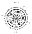
- valve 2 Function of the valve 2 is the hydraulic pressure on several pressure chambers 13a, 13b of the also in Fig. 5 distributed camshaft adjuster 1, so that a with a rotor 15 of the camshaft adjuster 1 axially and rotationally fixed camshaft 14 is pivoted in the one pivot direction or the opposite other pivoting direction.
- two pressure chambers 13a, 13b are associated with opposite directions of pivoting.
- the one of the pivoting direction associated pressure chambers 13a are connected via a in Fig. 2 closer apparent first working port A in the socket 11 is acted upon by a coming from a pressure medium port P pressure.
- the pressure chambers 13b associated with the opposite direction of rotation are acted upon via a second working port B with the pressure coming from the pressure medium connection P.
- the valve 2 further has two bypass ports A1 and B1.
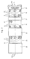
- the bushing 11 has three annular grooves 18, 19, 20, which are separated from each other by means of two annular webs 21, 22.
- the front - in the drawing plane right - annular groove 18 and the middle annular groove 19 correspond to recesses 23 and 25 in the camshaft 14 and recesses 24 and 26 in the rotor 15. These recesses 23, 24, 25, 26 lead to the pressure chambers 13a, 13b.
- the front annular groove 18 via the front recesses 25 of the camshaft 14 and the recesses 26 of the rotor 15 leads to the associated one direction of rotation pressure chambers 13b.
- the middle annular groove 19 leads via the rear recesses 23 of the camshaft 14 and the recesses 24 of the rotor 15 in the pressure chambers 13 a associated with the other direction of rotation.
- the rear annular groove 20 has a bore 27 which is connected to an annular channel 68, which is in communication with a fluid feed pump 30.
- an end-side annular web 28, 29 is provided at the ends of the bush 11, which prevents fluid leakage from the rear annular channel 20 and the front annular channel 18.
- radial bores in the groove bottom of the annular grooves are distributed circumferentially in defined angular positions.
- the front annular groove 18 from front to rear axially successive bores for the working port B and the bypass port B1.
- the middle annular groove 19 has From the front to the rear axially successive holes for the bypass port A1 and the working port A on.
- the left annular groove 20 has from front to rear axially successive holes for the pressure medium connection P.
- Fig. 3 and Fig. 4 show a valve 102 with a simplified piston 105, wherein with respect to the valve 2 according to Fig. 1 and Fig. 2 No bypass connections A1 and B1 are provided. Otherwise, the piston 105 is constructed equal to the piston 5.
- the opposite Fig. 1 and Fig. 2 Substantially modified components have increased by 100 reference numerals. Substantially identical components are also provided with the same reference numerals.
- Fig. 3 shows the piston 105 in a section analog Fig. 1
- Fig. 4 shows the piston 105, however, 90 ° rotated about its longitudinal axis 34.
- the piston 105 is in both Fig. 3 as well as in Fig. 4 shown in the foremost position. In this position, the piston 105 is pressed by a helical compression spring 31 when the electromagnetic actuator 4 is energized only slightly or not at all. In this case, a pressure chamber inlet channel 32 extends from the pressure medium connection P to the second working connection B. The pressure chambers 13b assigned to the working connection B are thus filled. At the same time runs to empty the other pressure chambers 13 a, the hydraulic fluid from the first working port A via an in Fig. 4 apparent pressure chamber outlet channel 33 to two tank drains T 1 , T 2 .
- the shape of the piston 105 makes it possible for the pressure chamber outlet channel 33 to be separated from the pressure chamber inlet channel 32, although these two are guided past one another. That is to say, the pressure chamber outlet channel 33 and the pressure chamber inlet channel 32 run partially in the same axial regions of the valve 102.
- the piston 105 has a substantially tubular basic shape with a tube wall 80.
- a slot 35 is provided along the longitudinal axis 34 of the piston 105.
- This slot 35 has a circumferentially closed wall 36, which separates the slot 35 against two in the tube on both sides of the wall 36 forming part-channels 65a, 65b.
- said end face 8 is arranged at the front end of the slot 35.
- an end face 37 is arranged, which supports the helical compression spring 31 elastically against a compression sleeve, which is pressed into the socket 11 to measure.
- the pressure chamber outlet channel 33 extends to the tank drains T 1 , T 2 through the two partial channels 65a, 65b.
- the pressure chamber inlet channel 32 extends through the slot 35.
- the helical compression spring need not be supported on the wall 36 of the piston 105, but in an alternative embodiment also on an in Fig. 4 paragraph 40.
- the piston 5 and 105 is produced by metal powder injection molding.
- the tube shape of the piston is exemplary.
- the piston has a complex integral geometry.
- One such manufacturing process is injection molding.
- the metal injection molding process metal injection molding
- Injection molding processes also include such processes as injection-compression molding.
- the separation of the pressure chamber discharge channel from the pressure chamber inlet channel takes place with a centrally extending slot. Due to the symmetry, the slot arranged centrally has the advantage that no torques act on the hydraulically actuated piston.
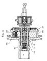
- Fig. 6 shows in a further embodiment, a central valve 202, which is incorporated directly into a central screw 211, which screws the rotor 215 of the camshaft adjuster 201 with the camshaft 214.
- a central screw 211 which screws the rotor 215 of the camshaft adjuster 201 with the camshaft 214.
- an internal thread is cut in the camshaft 214, in which the external thread of the central screw 211 is screwed.
- a lock 299 can be seen, by means of which the rotor 215 against a stator 298 rotatably locked. This lock 299 can be unlocked by a pressure in the two pressure chambers of the camshaft adjuster 201.
- the lock is in communication with the pressure medium connection, so that the lock is unlocked immediately depending on the working pressure, the locking analog Fig. 6 done by means of spring force.
- the camshaft adjuster is preferably designed as die gelzellenversteller.
- an axial piston adjuster which converts the axial movement into a pivoting movement of the camshaft via helical gearing.
- Such Axialkolbenversteller find especially in sporty engines with very strong valve springs of the gas exchange valves application, since there strong moment of change of the camshaft must be overcome as a result of the high valve spring forces, which are not forwarded to the axial piston by the self-locking effect of the helical teeth in Axialkolbenversteller.
- the camshaft may for example be a built camshaft.
- compression sleeve can also be provided a screwed sleeve, or it may be provided integrally with the socket manufactured bottom.
- the piston can also be displaced by means of a further hydraulic auxiliary piston.
- a further hydraulic auxiliary piston depending on the ratio, for example, a force amplification or a very fine positioning of the piston can be achieved.
- a tank drain on an end face of the piston or an end face of the socket suffice.
- a tank drain on an end face of the piston or an end face of the socket suffice.
- a massive design of the piston on one end face of the support surface for the helical compression spring can be increased and voltages can be kept low in the region of this support surface.
- the tank drains do not have to be arranged on the front side. So it is also possible to run the tank drains as radial holes in the piston and / or in the socket.
- the outer diameter of the bush or the piston can be rotated in a Spanabhub before the three annular grooves are turned off.
- the Socket and / or the piston also have stepped outer diameter, wherein the rearmost outer diameter is smallest and the front outer diameter is the largest.
- This is particularly advantageous for valves with sealing rings - in particular O-rings.
- These sealing rings can be used in annular grooves in the outer diameter.
- the sealing rings can be used in êtringnuten the rotor.
- the stepped design of the outer diameter prevents damage to the seals.
- Such sealing rings are particularly advantageous for valves for particularly high hydraulic pressures or high demands on the leak-tightness.
- the use of O-rings is also advantageous when using different materials for the valve components with different thermal expansion coefficients.
- the piston can be made of metal or plastic.
- the plastic is produced by injection molding. When using a plastic and a fiber reinforced plastic is advantageous, as this already in the unpublished DE 10 2007 026 831 is shown.
Landscapes
- Engineering & Computer Science (AREA)
- Mechanical Engineering (AREA)
- General Engineering & Computer Science (AREA)
- Valve-Gear Or Valve Arrangements (AREA)
- Valve Device For Special Equipments (AREA)
Abstract
Description
- Die Erfindung betrifft gemäß Patentanspruch 1 ein Ventil zum Verschwenken einer Nockenwelle.
- Aus der
DE 10 2005 041 393 A1 ist bereits ein Ventil für einen Nockenwellenversteller bekannt, das in Übereinstimmung mit der Erfindung einen Kolben aufweist, der längsverschieblich innerhalb einer Bohrung angeordnet ist. Von der Innenwand des Ventils gehen - ein Druckmittelanschluss P und
- zwei axial diesem unmittelbar folgende Arbeitsanschlüsse A und B ab. Der Kolben weist einen Druckkammer-Zulaufkanal und einen getrennt von diesem angeordneten Druckkammer-Ablaufkanal auf. Der Kolben soll in einer am Rande erwähnten Ausgestaltungsform auch aus Kunststoff oder in einem pulvermetallurgischen Spritzgiessverfahren hergestellt werden können. Dabei ist als Beispiel das Metal-Injection-Molding Verfahren aufgeführt.
- Die
DE 196 37 174 A1 zeigt ein Ventil für einen Nockenwellenversteller, bei welchem ein Kolben längsverschieblich innerhalb einer Bohrung mit einer Längsachse angeordnet ist. Von der Innenwand der Bohrung gehen zwei Arbeitsanschlüsse A, B und ein Druckmittelanschluss P ab. Der Druckmittelanschluss P ist dabei axial zwischen den beiden Arbeitsanschlüssen A, B angeordnet. - Aus der
DE 198 53 670 B4 ist ebenfalls ein Ventil für einen Nockenwellenversteller bekannt. Von der Innenwand der Bohrung gehen zwei Arbeitsanschlüsse A, B und ein Tankablauf T ab. Der Tankablauf T ist dabei axial zwischen den beiden Arbeitsanschlüssen A, B angeordnet. Ein stirnseitig am Ventil angeordneter Druckmittelanschluss P führt der Bohrung bzw. dem hohlen Kolben von innen Druck zu. - Aus der
DE 10 2004 038 252 A1 ist ein weiteres Ventil für einen Nockenwellenversteller bekannt. Von der Innenwand der Bohrung gehen axial aufeinander folgend ein Druckmittelanschluss P, ein Tankablauf T und zwei Arbeitsanschlüsse A, B ab. - Aufgabe der Erfindung ist es, einen axial sehr kurzen Nockenwellenversteller zu schaffen.
- Diese Aufgabe wird erfindungsgemäß mit den Merkmalen des Patentanspruchs 1 gelöst.
- Gemäß einem Vorteil der Erfindung folgt dem Druckmittelanschluss P unmittelbar der erste Arbeitsanschluss A. Diesem ersten Arbeitsanschluss A folgt der zweite Arbeitsanschluss B unmittelbar oder mittelbar. Infolge der unmittelbar oder mittelbar benachbarten Anordnung von den beiden Arbeitsanschlüssen A, B kann bei einem beispielsweise zentral zum Nockenwellenversteller angeordnetem Ventil der Nockenwellenversteller axial entsprechend schmal ausgeführt sein.
- Gemäß einem weiteren Vorteil der Erfindung ist der Druckmittelanschluss P axial nach bzw. vor den beiden Arbeitsanschlüssen A, B angeordnet. Somit kann dieser Druckmittelanschluss P außerhalb des Nockenwellenverstellers an Kanäle im Ventil angeschlossen sein, welche den Versorgungsdruck von einer Fluid-Förderpumpe zu den Arbeitsanschlüssen A bzw. B fördern können. Folglich sind Bohrungen im Nockenwellenversteller, welche den Versorgungsdruck von der Fluid-Förderpumpe zum Druckmittelanschluss P innerhalb des Nockenwellenverstellers leiten, nicht notwendig. Solche Bohrungen insbesondere durch den Rotor des Nockenwellenverstellers erhöhen den Bearbeitungsaufwand und schwächen den Rotor. In besonders vorteilhafter Weise wird demzufolge das Hydraulikfluid durch den Kolben des Ventils geführt.
- Der Druckmittelanschluss P kann hingegen vor oder hinter dem Nockenwellenversteller angeordnet sein. Die Anordnung hinter dem Nockenwellenversteller ist zu den zeichnerisch dargestellten Ausführungsformen dieser Anmeldung erläutert. Eine mögliche Anordnung des Druckmittelanschlusses P vor dem Nockenwellenversteller ist beispielsweise in der
DE 10 2004 038 252 A1 dargestellt. - Das Hydraulikfluid wird innerhalb des Kolbens über einen Druckkammer-Zulaufkanal vom Druckmittelanschluss P zu dem jeweiligen Arbeitsanschluss A bzw. B geleitet. Dieser Druckkammer-Zulaufkanal setzt sich aus zwei Querkanälen und einen zwischen diesen angeordneten Mittenkanal zusammen. Um den Kolben kostengünstig im Spritzgussverfahren herstellen zu können, stehen die Längen dieser Kanäle in einem Mindestverhältnis zueinander, dass die Längen der Querkanäle in Richtung der Längsachse des Kolbens gemeinsam zumindest ebenso lang sind, wie die Länge des dazwischen liegenden Mittenkanals.
- Es können zwischen den beiden Arbeitsanschlüssen A, B auch zusätzlich ein oder zwei Bypass-Anschlüsse A1, B1 vorgesehen sein.
- Das Ventil muss nicht als zentrales Ventil radial innerhalb des Nockenwellenverstellers angeordnet sein. Die Anordnung des Druckmittelanschlusses P axial neben den Arbeitsanschlüssen A, B anstelle zwischen den Arbeitsanschlüssen A, B bringt auch Vorteile bei einer externen Anordnung des Ventils. Bei einer solchen externen Anordnung ist das Ventil beispielsweise in
- einem Zylinderkopf,
- einem Zylinderkopfdeckel,
- einer Zwischenplatte bzw. Zwischenbrille zwischen dem Zylinderkopf und dem Nockenwellenversteller oder
- einem vor dem Nockenwellenversteller angeordneten Deckel
- Um axial besonders kurz zu bauen, kann in besonders vorteilhafter Weise ein Nockenwellenversteller Anwendung finden, der als Flügelzellenversteller ausgeführt ist. Die Erfindung kann jedoch auch Anwendung bei einem Nockenwellenversteller nach dem Axialkolbenprinzip oder einem Kettenversteller finden.
- Der Tankablauf T ist in vorteilhafter Weise
- weder zwischen den Arbeitsanschlüssen
- noch zwischen einem der Arbeitsanschlüsse und dem Druckmittelanschluss P angeordnet. Da jedoch erfindungsgemäß jeder der beiden Arbeitsanschlüsse A bzw. B vom Druckmittelanschluss P hydraulisch beaufschlagbar ist, während der jeweils andere Arbeitsanschluss B bzw. A hydraulisch mit Tankablauf T verbindbar ist, sind gemäß dem unabhängigen Patentanspruch 3 die beiden aneinander vorbei geführten Hydraulikflüsse vorgesehen. D.h. ein Druckkammer-Zulaufkanal kommt vom Druckmittelanschluss P, während ein Druckkammer-Ablaufkanal zum Tankablauf T verläuft. Damit verlaufen jedoch der Druckkammer-Zulaufkanal und der Druckkammer-Ablaufkanal zumindest teilweise in den gleichen axialen Bereichen des Ventils. Dies macht eine Trennung der beiden Kanäle voneinander notwendig. Diese Trennung kann beispielsweise mittels eines Schlitzes erfolgen, welcher den rohrförmig ausgestalteten Kolben in zwei Kanäle aufteilt und selber einen eigenständigen Kanal bildet.
- In einer besonders vorteilhaften Ausgestaltung der Erfindung sind zum schnellen entleeren der Druckkammern zwei Tankanschlüsse vorgesehen. Diese beiden Tankanschlüsse können in einer weiteren vorteilhaften Ausgestaltung an den beiden Stirnenden des Ventils vorgesehen sein.
- Der Kolben ist in einer Bohrung axial geführt. Die Bohrung kann in besonders vorteilhafter Weise in der Buchse eines cartridge-Ventils eingearbeitet sein. Jedoch kann die Bohrung auch in einem Gehäuse angeordnet sein. In einer besonders vorteilhaften Ausführungsform ist die Bohrung unmittelbar in eine Zentralschraube eingearbeitet, welche den Rotor des Nockenwellenverstellers mit der Nockenwelle verschraubt.
- Weitere Vorteile der Erfindung gehen aus den weiteren Patentansprüchen, der Beschreibung und der Zeichnung vor.
- Die Erfindung ist nachfolgend anhand von drei Ausführungsbeispielen näher erläutert.
- Dabei zeigen
-
Fig. 1 in einer geschnittenen Darstellung ein Detail eines Verbrennungsmotors im Bereich eines Nockenwellenverstellers mit einem zentralen Ventil, welches Bypass-Anschlüsse aufweist. -
Fig. 2 das Ventil ausFig. 1 in einer nicht geschnittenen Darstellung, -
Fig. 3 in einer zweiten Ausgestaltungsform ein Ventil ohne Bypass-Anschlüsse in einer geschnittenen Darstellung, -
Fig. 4 das Ventil ausFig. 3 in einer geschnittenen Darstellung 90° um dessen Längsachse gedreht, -
Fig. 5 einen Nockenwellenversteller zum Verschwenken einer Nockenwelle, wobei dazu ein Ventil gemäß den ersten beiden Ausgestaltungsformen Anwendung finden kann und -
Fig. 6 in einer dritten Ausgestaltungsform ein zentrales Ventil, welches unmittelbar in eine Zentralschraube eingearbeitet ist, welche den Rotor des Nockenwellenverstellers mit der Nockenwelle verschraubt. -
Fig. 1 zeigt ein Detail eines Verbrennungsmotors im Bereich eines Nockenwellenverstellers 1. Dieser Nockenwellenversteller 1 ist mit einem zentral angeordneten Ventil 2 versehen, dass als 4/3-Wege-Proportionalventil ausgeführt ist. - Das Ventil 2 ist dabei als sogenanntes Cartridge-Ventil ausgeführt und umfasst einen hydraulischen Teil 3 und einen elektromagnetischen Aktor 4. Bei diesem Ventil 2 ist der elektromagnetische Aktor 4 fluchtend zu einem Kolben 5 des hydraulischen Teils 3 angeordnet. Ein Anlagekörper 6 eines Stößels 7 des Aktors 4 liegt an der Stirnfläche 8 des Kolbens 5 an. Ein Gehäuse 9 und ein Polkern 10 des elektromagnetischen Aktors 4 sind über eine nicht näher dargestellte Gehäuseverbindung axialfest mit einer Buchse 11 des hydraulischen Teils 3 verbunden, in deren zentrischer Bohrung 12 der Kolben 5 axial verschieblich geführt ist. Diese Axialverschiebung erfolgt infolge Bestromung des elektromagnetischen Aktors 4 gegen die Federkraft eine Schraubendruckfeder 31.
- Funktion des Ventils 2 ist es, den hydraulischen Druck auf mehrere Druckkammern 13a, 13b des auch in
Fig. 5 dargestellten Nockenwellenverstellers 1 zu verteilen, so dass eine mit einem Rotor 15 des Nockenwellenverstellers 1 axial- und drehfest verbundene Nockenwelle 14 in die eine Schwenkrichtung oder die entgegen gesetzte andere Schwenkrichtung verschwenkt wird. Dabei sind jeweils zwei Druckkammern 13a, 13b entgegen gerichteten Schwenkrichtungen zugeordnet. Die der einen Schwenkrichtung zugeordneten Druckkammern 13a werden über einen inFig. 2 näher ersichtlichen ersten Arbeitsanschluss A in der Buchse 11 mit einem von einem Druckmittelanschluss P kommenden Druck beaufschlagt. Die der entgegen gesetzten Drehrichtung zugeordneten Druckkammern 13b werden über einen zweiten Arbeitsanschluss B mit dem vom Druckmittelanschluss P kommenden Druck beaufschlagt. Während die einen Druckkammern 13a bzw. 13b gefüllt werden und sich demzufolge vergrößern, verkleinern sich die entgegen gesetzten anderen Druckkammern 13b bzw. 13a zwangsläufig. Das dabei aus den anderen Druckkammern 13b bzw. 13a verdrängte Fluid wird dabei zu zwei Tankabläufen T1,T2 geleitet, welche an den beiden offenen Stirnseiten 64a, 64b der Buchse 11 austreten. Das Ventil 2 weist ferner zwei Bypass-Anschlüsse A1 und B1 auf. - Diese Bypass-Anschlüsse A1 und B1 weisen in
Fig. 1 ersichtliche blattfederartige Rückschlagventile 16, 17 auf, mit denen das rücklaufende Hydraulikfluid aus der zu entleerenden anderen Druckkammer 13b bzw. 13a in die zu befüllende Druckkammer 13a bzw. 13b geleitet werden kann, falls der Druck in der zu entleerenden Druckkammer 13b bzw. 13a über den Druck der zu befüllenden Druckkammer 13a bzw. 13b steigt. Diese Funktion zur schnelleren Verschwenkung der Nockenwelle 14 ist in derDE 10 2006 012 733 B4 und derDE 10 2006 012 775 B4 näher beschrieben und soll in dieser Anmeldung als aufgenommen gelten. Ebenso soll dieDE 10 2005 013 085 B3 als aufgenommen gelten, in der die blattfederartigen Rückschlagventile 16, 17 näher dargestellt sind. - Im Folgenden wird der Aufbau des hydraulischen Teils 3 des Ventils 2 näher dargestellt.
- Gemäß
Fig. 2 weist die Buchse 11 drei Ringnuten 18, 19, 20 auf, welche mittels zwei Ringstegen 21, 22 voneinander getrennt sind. Die vordere - in der Zeichnungsebene rechte - Ringnut 18 und die mittlere Ringnut 19 korrespondieren mit Ausnehmungen 23 bzw. 25 in der Nockenwelle 14 und Ausnehmungen 24 bzw. 26 in dem Rotor 15. Diese Ausnehmungen 23, 24, 25, 26 führen zu den Druckkammern 13a, 13b. Dabei führt die vordere Ringnut 18 über die vorderen Ausnehmungen 25 der Nockenwelle 14 und den Ausnehmungen 26 des Rotors 15 zu den der einen Drehrichtung zugeordneten Druckkammern 13b. Hingegen führt die mittlere Ringnut 19 über die hinteren Ausnehmungen 23 der Nockenwelle 14 und den Ausnehmungen 24 des Rotors 15 in die der anderen Drehrichtung zugeordneten Druckkammern 13a. In die hintere Ringnut 20 führt eine Bohrung 27, die an einen Ringkanal 68, angeschlossen ist, welcher mit einer Fluid-Förderpumpe 30 in Verbindung steht. Außer den beiden mittleren Ringstegen 22, 21 ist an den Enden der Buchse 11 jeweils ein endseitiger Ringsteg 28, 29 vorgesehen, der einen Fluidaustritt aus dem hinteren Ringkanal 20 bzw. dem vorderen Ringkanal 18 verhindert. - Um den hydraulischen Fluss von der Fluid-Förderpumpe den jeweiligen Druckkammern zuzuordnen, sind radiale Bohrungen im Nutgrund der Ringnuten umfangsmäßig in definierten Winkelpositionen verteilt. Dabei weist die vordere Ringnut 18 von vorne nach hinten axial aufeinander folgend Bohrungen für den Arbeitsanschluss B und den Bypass-Anschluss B1 auf. Die mittlere Ringnut 19 weist von vorne nach hinten axial aufeinander folgend Bohrungen für den Bypass-Anschluss A1 und den Arbeitsanschluss A auf. Die linke Ringnut 20 weist von vorne nach hinten axial aufeinander folgend Bohrungen für den Druckmittelanschluss P auf. Je nach axialer Position des Kolbens 5 - und damit je nach zu beaufschlagenden Druckkammern 13a bzw. 13b- wird Hydraulikfluid von der Fluid-Förderpumpe 30 über eine Bohrung 69 und einen Ringkanal 68 eines Nockenwellenlagers 70 und den Ringkanal 20 zu den beiden Arbeitsanschlüssen A bzw. B geleitet, so dass der Rotor 15 in die eine Drehrichtung oder die entgegen gesetzte Drehrichtung verschwenkt.
-
Fig. 3 undFig. 4 zeigen ein Ventil 102 mit einem vereinfachten Kolben 105, wobei gegenüber dem Ventil 2 gemäßFig. 1 undFig. 2 keine Bypass-Anschlüsse A1 und B1 vorgesehen sind. Ansonsten ist der Kolben 105 gleich dem Kolben 5 aufgebaut. Die gegenüberFig. 1 undFig. 2 wesentlich veränderten Bauteile weisen um 100 erhöhte Bezugsziffern auf. Im Wesentlichen gleiche Bauteile sind auch mit gleichen Bezugsziffern versehen.Fig. 3 zeigt den Kolben 105 in einem Schnitt analogFig. 1 .Fig. 4 zeigt den Kolben 105 hingegen 90° um dessen Längsachse 34 gedreht. - Der Kolben 105 ist sowohl in
Fig. 3 als auch inFig. 4 in der vordersten Position dargestellt. In diese Position wird der Kolben 105 von einer Schraubendruckfeder 31 gedrückt, wenn der elektromagnetische Aktor 4 nur geringfügig oder überhaupt nicht bestromt ist. Dabei verläuft ein Druckkammer-Zulaufkanal 32 von dem Druckmittelanschluss P zum zweiten Arbeitsanschluss B. Damit werden die dem Arbeitsanschluss B zugeordneten Druckkammern 13b befüllt. Zeitgleich verläuft zum Entleeren der anderen Druckkammern 13a das Hydraulikfluid vom ersten Arbeitsanschluss A über einen inFig. 4 ersichtlichen Druckkammer-Ablaufkanal 33 zu zwei Tankabläufen T1, T2. Dabei ermöglicht es die Formgebung des Kolbens 105, dass der Druckkammer-Ablaufkanal 33 vom Druckkammer-Zulaufkanal 32 getrennt ist, obwohl diese beiden aneinander vorbei geführt werden. D.h. der Druckkammer-Ablaufkanal 33 und der Druckkammer-Zulaufkanal 32 verlaufen teilweise in den gleichen axialen Bereichen des Ventils 102. - Insbesondere aus
Fig. 4 ist ersichtlich, dass der Kolben 105 im Wesentlichen eine rohrförmige Grundform mit einer Rohrwand 80 aufweist. Entlang der Längsachse 34 des Kolbens 105 ist ein Schlitz 35 vorgesehen. Dieser Schlitz 35 weist eine umlaufend geschlossene Wandung 36 auf, die den Schlitz 35 gegenüber zwei sich im Rohr beidseitig der Wandung 36 bildende Teilkanäle 65a, 65b trennt. An dem vorderen Ende des Schlitzes 35 ist die besagte Stirnfläche 8 angeordnet. An dem hinteren Ende der Wandung 36 ist eine Stirnfläche 37 angeordnet, welche die Schraubendruckfeder 31 elastisch gegen eine Presshülse abstützt, die auf Maß in die Buchse 11 eingepresst ist. - Aus der Schnittebene gemäß
Fig. 3 wiederum ist ersichtlich, dass der Kolben 5 zwei Querkanäle aufweist, die einen Einlasskanal 91 und einen Auslasskanal 93 umfassen. Der Druckkammer-Zulaufkanal 32 verläuft vom Druckmittelanschluss P durch - den sich quer durch den Kolben 5 erstreckenden Einlasskanal 91,
- einen sich zentral längs des Kolbens 5 erstreckenden Mittenkanal 92 und
- den sich quer durch den Kolben 5 erstreckenden Auslasskanal 93 zum zweiten Arbeitsanschluss B. In Bezug auf die Längsachse 34 weisen
- der Einlasskanal 91 eine Länge LP,
- der Mittenkanal 92 eine Länge LM und
- der Auslasskanal 93 ein Länge LAB
- In der dargestellten Stellung des Kolbens 105 verläuft der Druckkammer-Ablaufkanal 33 zu den Tankabläufen T1,T2 durch die beiden Teilkanäle 65a, 65b. Hingegen verläuft der Druckkammer-Zulaufkanal 32 durch den Schlitz 35.
- In der zeichnerisch nicht dargestellten hinteren Stellung des Kolbens 105 bei maximal ausgerücktem elektromagnetischen Aktor 4 ist die Schraubendruckfeder 31 gestaucht. Der vom Druckanschluss P kommende Druck wird durch den Druckkammer-Zulaufkanal 32 zum ersten Arbeitsanschluss A geleitet. Der zweite Arbeitsanschluss B wird an der axial äußeren Ablaufkante 66 des Kolbens 105 vorbei zu den beiden stirnseitigen Tankabläufen T1,T2 geleitet. Am vorderen Ende des Ventils 2 fließt das Hydraulikfluid direkt vom zweiten Arbeitsanschluss B zum stirnseitigen vorderen Tankablauf T1. Zum hinteren stirnseitigen Tankablauf T2 am hinteren Ende des Ventils 2 fließt das Hydraulikfluid hingegen an der Ablaufkante 66 vorbei durch die beiden Teilkanäle 65a, 65b des Kolbens 105.
- Die Schraubendruckfeder muss nicht an der Wandung 36 des Kolbens 105 abgestützt sein, sondern kann in einer alternativen Ausführungsform auch an einem in
Fig. 4 ersichtlichen Absatz 40 abgestützt sein. - Der Kolben 5 bzw. 105 ist im Metallpulverspritzgießverfahren hergestellt.
- Die Rohrform des Kolbens ist beispielhaft. Insbesondere bei Herstellungsverfahren, die eine komplexe Formgebung ermöglichen, weist der Kolben eine komplexe integrale Geometrie auf. Ein solche Herstellungsverfahren ist der Spritzguss. Zur Herstellung der komplexen Geometrie kann insbesondere das Metallpulverspritzgießverfahren (Metal Injection Molding) verwendet werden. Zu den Spritzgussverfahren zählen auch solche Verfahren, wie das Spritzprägen.
- Die Trennung des Druckkammer-Ablaufkanals von dem Druckkammer-Zulaufkanal erfolgt mit einem mittig verlaufenden Schlitz. Der mittig angeordnete Schlitz hat infolge der Symmetrie den Vorteil, dass keine Drehmomente auf den hydraulisch beaufschlagten Kolben wirken.
-
Fig. 6 zeigt in einer weiteren Ausgestaltungsform ein zentrales Ventil 202, welches unmittelbar in eine Zentralschraube 211 eingearbeitet ist, welche den Rotor 215 des Nockenwellenverstellers 201 mit der Nockenwelle 214 verschraubt. Dazu ist in der Nockenwelle 214 ein Innengewinde eingeschnitten, in welches das Außengewinde der Zentralschraube 211 eingeschraubt ist. Dabei ist auch eine Verriegelung 299 ersichtlich, mittels welcher der Rotor 215 gegenüber einem Stator 298 drehfest verriegelbar ist. Diese Verriegelung 299 ist von einem Druck in den beiden Druckkammern des Nockenwellenverstellers 201 entriegelbar. - In einer alternativen Ausgestaltungsform steht die Verriegelung in Verbindung mit dem Druckmittelanschluss, so dass die Verriegelung unmittelbar abhängig vom Arbeitsdruck entriegelt wird, wobei die Verriegelung analog
Fig. 6 mittels Federkraft erfolgt. - Der Nockenwellenversteller ist vorzugsweise als Flügelzellenversteller ausgeführt. Ebenso ist es jedoch auch möglich, einen Axialkolbenversteller zu verwenden, der über eine Schrägverzahnung die Axialbewegung in eine Schwenkbewegung der Nockenwelle umwandelt. Solche Axialkolbenversteller finden insbesondere bei sportlichen Motoren mit sehr starken Ventilfedern der Gaswechselventile Anwendung, da dort infolge der hohen Ventilfederkräfte starke Wechselmomente der Nockenwelle überwunden werden müssen, die durch die selbsthemmende Wirkung der Schrägverzahnung beim Axialkolbenversteller nicht an dessen Axialkolben weitergeleitet werden.
- Das Ventil muss nicht als Cartridge-Ventil ausgeführt sein. Es kann auch auf die Buchse verzichtet werden. Der Kolben kann dann unmittelbar in einer Bohrung des Rotors oder eines Gehäuses eingesetzt sein. Dieses Gehäuse kann beispielsweise der Zylinderkopf oder ein mit dem Zylinderkopf verbundener Deckel bzw. eine Zwischenplatte sein. Auch kann der Kolben unmittelbar
- in eine Bohrung der Nockenwelle oder
- die als Hohlwelle ausgeführte Nockenwelle
- Die Nockenwelle kann beispielsweise eine gebaute Nockenwelle sein.
- Anstelle der Presshülse kann auch eine geschraubte Hülse vorgesehen sein, oder es kann ein integral mit der Buchse gefertigter Boden vorgesehen sein.
- Anstelle eines elektromagnetischen Aktors kann der Kolben auch mittels eines weiteren hydraulischen Hilfskolbens verschoben werden. Mit solch einem Hilfskolben kann je nach Übersetzung beispielsweise auch eine Kraftverstärkung oder eine sehr feine Positionierung des Kolbens erreicht werden.
- Es müssen nicht zwei Tankabläufe vorgesehen sein. So kann ein Tankablauf auf einer Stirnseite des Kolbens bzw. einer Stirnseite der Buchse ausreichen. Insbesondere, wenn das Fluid von einer Stirnseite nicht weiter geleitet werden kann/soll, reicht ein Tankablauf aus. Auch kann durch eine massive Ausführung des Kolbens auf dessen einer Stirnseite die Auflagefläche für die Schraubendruckfeder vergrößert werden und Spannungen können im Bereich dieser Auflagefläche gering gehalten werden.
- Die Tankabläufe müssen nicht stirnseitig angeordnet sein. So ist es auch möglich, die Tankabläufe als radiale Bohrungen im Kolben und/oder in der Buchse auszuführen.
- Der Außendurchmesser der Buchse oder des Kolbens kann in einem Spanabhub gedreht werden, bevor die drei Ringnuten ausgedreht werden. Alternativ kann die Buchse und/oder der Kolben auch gestufte Außendurchmesser aufweisen, wobei der hinterste Außendurchmesser am kleinsten ist und der vorderste Außendurchmesser am größten ist. Dies ist insbesondere bei Ventilen mit Dichtringen - insbesondere O-Ringen - von Vorteil. Diese Dichtringe können in Ringnuten im Bereich der Außendurchmesser eingesetzt sein. Ebenso können die Dichtringe in Innenringnuten des Rotors eingesetzt sein. Die gestufte Ausführung der Außendurchmesser verhindert dabei die Beschädigung der Dichtringe. Solche Dichtringe sind insbesondere bei Ventilen für besonders hohe Hydraulikdrücke oder mit hohen Anforderungen an die Leckagedichtheit von Vorteil. Die Verwendung von O-Ringen ist ferner beim Einsatz von unterschiedlichen Werkstoffen für die Ventilbauteile mit unterschiedlichen Wärmeausdehnungskoeffizienten von Vorteil.
- Die Fluid-Förderpumpe kann insbesondere die Ölpumpe zur Schmiermittelversorgung des Verbrennungsmotors sein. Soll jedoch für eine hohe Verstellgeschwindigkeit des Nockenwellenstellers ein relativ hoher Druck aufgebracht werden, kann die Fluid-Förderpumpe
- nur dem Nockenwellenversteller oder
- dem Nockenwellenversteller und weiteren Hydraulikaggregaten zugeordnet sein. In diesem Fall kann die Fluid-Förderpumpe beispielsweise als Flügelzellenpumpe ausgeführt sein. Alternativ sind Zahnradpumpen, Radialkolbenpumpen und Mondsichelpumpen möglich.
- Es versteht sich von selbst, dass die Bezeichnung der beiden Arbeitsanschlüsse mit den Buchstaben A oder B willkürlich ist und untereinander austauschbar ist.
- Der Kolben kann aus Metall oder aus Kunststoff gefertigt sein. Der Kunststoff wird im Spritzguss hergestellt. Bei der Verwendung eines Kunststoffs ist auch ein faserverstärkter Kunststoff von Vorteil, wie dieser bereits in der nicht vorveröffentlichten
DE 10 2007 026 831 dargestellt ist. - Zur Herstellung des Kolbens wird ein Werkzeug mit Schiebern verwendet.
- Bei den beschriebenen Ausführungsformen handelt es sich nur um beispielhafte Ausgestaltungen. Eine Kombination der beschriebenen Merkmale für unterschiedliche Ausführungsformen ist ebenfalls möglich. Weitere, insbesondere nicht beschriebene Merkmale der zur Erfindung gehörenden Vorrichtungsteile, sind den in den Zeichnungen dargestellten Geometrien der Vorrichtungsteile zu entnehmen.
Claims (12)
- Ventil (2) für einen Nockenwellenversteller (1), bei welchem ein Kolben (5) längsverschieblich innerhalb einer Bohrung (12) angeordnet ist, von deren Innenwand (79)- ein Druckmittelanschluss (P) und- axial diesem unmittelbar folgend ein erster Arbeitsanschluss (A) und- axial dem Druckmittelanschluss (P) und dem ersten Arbeitsanschluss (A) folgend ein zweiter Arbeitsanschluss (B)abgehen, wobei der Kolben (5) einen Druckkammer-Zulaufkanal (32) und einen getrennt von diesem angeordneten Druckkammer-Ablaufkanal (33) aufweist, wobei der Kolben (5 bzw. 105) eine im wesentlichen rohrförmige Rohrwand (80) mit einem mittigen Schlitz (35) aufweist, dessen Wandung (36) sich der Rohrwand (80) anschließt, so dass die Wandung (36) des Schlitzes (35) den einen Druckkammer-Ablaufkanal (33) von einem Druckkammer-Zulaufkanal (32) trennt, wobei sich der Druckkammer-Ablaufkanal (33) entlang des Schlitzes in zwei Teilkanäle (65a, 65b) aufteilt, wobei der Kolben (11) in einem Spritzgussverfahren hergestellt ist und wobei der Druckkammer-Zulaufkanal (32) durch- einen quer zu einer Längsachse (34) des Kolbens verlaufenden Einlasskanal (91) mit einer Länge LP bezüglich der Längsachse (34),- einen entlang der Längsachse (34) verlaufenden Mittenkanal (92) mit einer Länge LM bezüglich der Längsachse (34) und- einen quer zur Längsachse (34) verlaufenden Auslasskanal (93) mit einer Länge LAB bezüglich der Längsachse (34)verläuft, wobei für die Längen LM ≤ LP + LAB gilt.
- Ventil nach Patentanspruch 1,
dadurch gekennzeichnet, dass
in den Druckmittelanschluss (P) ein Rückschlagventil (77) einsetzt ist. - Ventil nach Patentanspruch 2,
dadurch gekennzeichnet, dass
das Rückschlagventil (77) als Band (76) ausgeführt ist, welches in eine Innenringnut (78) eingelegt ist, die von der Innenwand (79) der Bohrung (12) abgeht. - Ventil nach einem der vorhergehenden Patentansprüche,
dadurch gekennzeichnet, dass
der Tankablauf (T1 bzw. T2) stirnseitig aus dem Kolben (11) austritt. - Ventil nach Patentanspruch 4
dadurch gekennzeichnet, dass
beidseitig des Kolbens (11) Tankabläufe (T1, T2) austreten. - Ventil nach einem der vorhergehenden Patentansprüche,
dadurch gekennzeichnet, dass
axial zwischen den beiden Arbeitsanschlüssen (A, B) zumindest ein Bypass-Anschluss (A1 bzw. B1) vorgesehen ist, mit dem das Hydraulikfluid der zu entleerenden Druckkammer in die zu befüllende Druckkammer geleitet werden kann, falls der Druck in der zu entleerenden Druckkammer über den Druck der zu befüllenden Druckkammer steigt. - Ventil nach Patentanspruch 6,
dadurch gekennzeichnet, dass
axial zwischen den beiden Arbeitsanschlüssen (A, B) zwei Bypass-Anschlüsse (A1, B1) unmittelbar benachbart zueinander vorgesehen sind. - Ventil nach Patentanspruch 6 oder 7,
dadurch gekennzeichnet, dass
der Bypass-Anschluss (A1 bzw. B1) ein Rückschlagventil (16 bzw. 17) umfasst, dass als Band ausgeführt ist, welches in eine Innenringnut (75 bzw. 74) eingelegt ist, die von der Innenwand (79) der Bohrung (12) abgeht. - Ventil nach einem der vorhergehenden Patentansprüche,
dadurch gekennzeichnet, dass
das Ventil (2) fluchtend zu einer Nockenwelle (14) angeordnet ist, wobei ein elektromagnetischer Aktor (4) auf einer dem Zylinderkopf gegenüber liegenden Seite des Nockenwellenverstellers (1) angeordnet ist, wohingegen der Druckmittelanschluss (P) auf der anderen Seite des Nockenwellenverstellers (1) angeordnet ist. - Ventil nach einem der vorhergehenden Patentansprüche,
dadurch gekennzeichnet, dass
das Ventil (2) fluchtend zu einer Nockenwelle (14) angeordnet ist, wobei ein elektromagnetischer Aktor (4) auf einer dem Zylinderkopf gegenüber liegenden Seite des Nockenwellenverstellers (1) angeordnet ist, wohingegen auf der anderen Seite des Nockenwellenverstellers (1) eine Bohrung (27) in der Nockenwelle (14) vorgesehen ist, in welche der Druckmittelanschluss (P) mündet. - Ventil nach einem der Patentansprüche 9 oder 10,
dadurch gekennzeichnet, dass
der Druckmittelanschluss (P) zumindest indirekt in eine Ausnehmung des Nockenwellenlagers (70) mündet. - Ventil dem vorhergehenden Patentanspruch,
dadurch gekennzeichnet, dass
der Kolben im Metallpulverspritzgießverfahren (MIM) hergestellt ist.
Applications Claiming Priority (1)
| Application Number | Priority Date | Filing Date | Title |
|---|---|---|---|
| DE102008028846 | 2008-06-19 |
Publications (3)
| Publication Number | Publication Date |
|---|---|
| EP2136041A2 true EP2136041A2 (de) | 2009-12-23 |
| EP2136041A3 EP2136041A3 (de) | 2010-07-14 |
| EP2136041B1 EP2136041B1 (de) | 2011-06-08 |
Family
ID=41082411
Family Applications (1)
| Application Number | Title | Priority Date | Filing Date |
|---|---|---|---|
| EP09005039A Not-in-force EP2136041B1 (de) | 2008-06-19 | 2009-04-06 | Ventil zum Verschwenken einer Nockenwelle |
Country Status (2)
| Country | Link |
|---|---|
| EP (1) | EP2136041B1 (de) |
| AT (1) | ATE512285T1 (de) |
Cited By (5)
| Publication number | Priority date | Publication date | Assignee | Title |
|---|---|---|---|---|
| EP2386731A1 (de) * | 2010-05-03 | 2011-11-16 | Hydraulik-Ring GmbH | Hydraulikventil |
| DE102010060181A1 (de) * | 2010-10-26 | 2012-04-26 | Hydraulik-Ring Gmbh | Zentralventil |
| DE102010060180A1 (de) * | 2010-10-26 | 2012-04-26 | Hydraulik-Ring Gmbh | Zentralventil |
| WO2012055597A1 (de) * | 2010-10-25 | 2012-05-03 | Schaeffler Technologies AG & Co. KG | Steuerventil für einen nockenwellenversteller |
| US9729024B2 (en) | 2014-12-12 | 2017-08-08 | Denso Corporation | Solenoid actuator |
Citations (8)
| Publication number | Priority date | Publication date | Assignee | Title |
|---|---|---|---|---|
| DE19637174A1 (de) | 1995-09-13 | 1997-03-27 | Aisin Seiki | Schaltventil |
| DE102004038252A1 (de) | 2004-05-14 | 2005-12-15 | Ina-Schaeffler Kg | Steuerventil für eine Vorrichtung zur Veränderung der Steuerzeiten einer Brennkraftmaschine |
| DE102005013085B3 (de) | 2005-03-18 | 2006-06-01 | Hydraulik-Ring Gmbh | Ventil mit Rückschlagventil |
| DE102005041393A1 (de) | 2005-09-01 | 2007-03-08 | Schaeffler Kg | Steuerventil für eine Vorrichtung zur Veränderung der Steuerzeiten einer Brennkraftmaschine |
| DE19853670B4 (de) | 1998-11-20 | 2007-07-26 | Hydraulik-Ring Gmbh | Einrichtung zur Nockenwellenverstellung |
| DE102006012775B4 (de) | 2006-03-17 | 2008-01-31 | Hydraulik-Ring Gmbh | Fast cam phaser-Hydraulikkreis, insbesondere für Nockenwellenversteller, und entsprechendes Steuerelement |
| DE102006012733B4 (de) | 2006-03-17 | 2008-03-27 | Hydraulik-Ring Gmbh | Fast cam phaser-Hydraulikkreis, insbesondere für Nockenwellenversteller, und entsprechendes Steuerelement |
| DE102007026831B3 (de) | 2007-06-06 | 2008-10-02 | Hydraulik-Ring Gmbh | Elektrohydraulisches Ventil |
Family Cites Families (1)
| Publication number | Priority date | Publication date | Assignee | Title |
|---|---|---|---|---|
| GB0303571D0 (en) * | 2003-02-17 | 2003-03-19 | Delphi Tech Inc | Oil flow control valve for a cam phaser |
-
2009
- 2009-04-06 AT AT09005039T patent/ATE512285T1/de active
- 2009-04-06 EP EP09005039A patent/EP2136041B1/de not_active Not-in-force
Patent Citations (8)
| Publication number | Priority date | Publication date | Assignee | Title |
|---|---|---|---|---|
| DE19637174A1 (de) | 1995-09-13 | 1997-03-27 | Aisin Seiki | Schaltventil |
| DE19853670B4 (de) | 1998-11-20 | 2007-07-26 | Hydraulik-Ring Gmbh | Einrichtung zur Nockenwellenverstellung |
| DE102004038252A1 (de) | 2004-05-14 | 2005-12-15 | Ina-Schaeffler Kg | Steuerventil für eine Vorrichtung zur Veränderung der Steuerzeiten einer Brennkraftmaschine |
| DE102005013085B3 (de) | 2005-03-18 | 2006-06-01 | Hydraulik-Ring Gmbh | Ventil mit Rückschlagventil |
| DE102005041393A1 (de) | 2005-09-01 | 2007-03-08 | Schaeffler Kg | Steuerventil für eine Vorrichtung zur Veränderung der Steuerzeiten einer Brennkraftmaschine |
| DE102006012775B4 (de) | 2006-03-17 | 2008-01-31 | Hydraulik-Ring Gmbh | Fast cam phaser-Hydraulikkreis, insbesondere für Nockenwellenversteller, und entsprechendes Steuerelement |
| DE102006012733B4 (de) | 2006-03-17 | 2008-03-27 | Hydraulik-Ring Gmbh | Fast cam phaser-Hydraulikkreis, insbesondere für Nockenwellenversteller, und entsprechendes Steuerelement |
| DE102007026831B3 (de) | 2007-06-06 | 2008-10-02 | Hydraulik-Ring Gmbh | Elektrohydraulisches Ventil |
Cited By (9)
| Publication number | Priority date | Publication date | Assignee | Title |
|---|---|---|---|---|
| EP2386731A1 (de) * | 2010-05-03 | 2011-11-16 | Hydraulik-Ring GmbH | Hydraulikventil |
| WO2012055597A1 (de) * | 2010-10-25 | 2012-05-03 | Schaeffler Technologies AG & Co. KG | Steuerventil für einen nockenwellenversteller |
| CN103189605A (zh) * | 2010-10-25 | 2013-07-03 | 谢夫勒科技股份两合公司 | 用于凸轮轴调节器的控制阀 |
| CN103189605B (zh) * | 2010-10-25 | 2015-08-05 | 谢夫勒科技股份两合公司 | 用于凸轮轴调节器的控制阀 |
| DE102010060181A1 (de) * | 2010-10-26 | 2012-04-26 | Hydraulik-Ring Gmbh | Zentralventil |
| DE102010060180A1 (de) * | 2010-10-26 | 2012-04-26 | Hydraulik-Ring Gmbh | Zentralventil |
| DE102010060181B4 (de) | 2010-10-26 | 2014-08-21 | Hilite Germany Gmbh | Zentralventil |
| DE102010060180B4 (de) * | 2010-10-26 | 2017-06-29 | Hilite Germany Gmbh | Zentralventil |
| US9729024B2 (en) | 2014-12-12 | 2017-08-08 | Denso Corporation | Solenoid actuator |
Also Published As
| Publication number | Publication date |
|---|---|
| ATE512285T1 (de) | 2011-06-15 |
| EP2136041B1 (de) | 2011-06-08 |
| EP2136041A3 (de) | 2010-07-14 |
Similar Documents
| Publication | Publication Date | Title |
|---|---|---|
| EP2870327B1 (de) | Schwenkmotorversteller mit einem hydraulikventil | |
| DE19717295C2 (de) | Fluid-Maschine | |
| DE102004035035A1 (de) | Nockenwellenversteller für Brennkraftmaschinen | |
| EP3219941A1 (de) | Hydraulikventil für einen schwenkmotorversteller einer nockenwelle | |
| EP2136041B1 (de) | Ventil zum Verschwenken einer Nockenwelle | |
| EP2370714B1 (de) | Elektromagnetische stelleinheit | |
| DE102016120975A1 (de) | Längenverstellbare Pleuelstange mit einer Zylinder-Kolben-Einheit mit Ölfilter | |
| DE102010032133A1 (de) | Zentralventil | |
| DE102016120967A1 (de) | Längenverstellbare Pleuelstange mit einer Zylinder-Kolben-Einheit mit mehreren Kolbendichtungen | |
| DE102011056264B4 (de) | Hydraulikventil | |
| EP1205652A1 (de) | Variables Kompressionsverhältnis, zwei durch Öldruck betätigte Ventile in der Kurbelwelle | |
| EP0669469B1 (de) | Fluidisch betätigbarer Drehantrieb | |
| DE102005051324A1 (de) | Spülventil für einen hydraulischen Kreislauf | |
| EP3530891B1 (de) | Hydraulikventil für einen schwenkmotorversteller einer nockenwelle | |
| AT519304A2 (de) | Längenverstellbare Pleuelstange mit einer Zylinder-Kolben-Einheit mit Ölabstreifer | |
| DE102010013777A1 (de) | Zentralventil | |
| DE102011000591B4 (de) | Zentralventil für einen Schwenkmotorversteller | |
| DE102012208808A1 (de) | Steuerventil zur Steuerung von Druckmittelströmen eines Nockenwellenverstellers | |
| EP3530892A1 (de) | Hydraulikventil für einen schwenkmotorversteller einer nockenwelle | |
| DE102014115903A1 (de) | Hydraulikventil und Schwenkmotorversteller | |
| DE102019101115A1 (de) | Hydraulikventil für einen Schwenkmotorversteller einer Nockenwelle | |
| DE102017107719A1 (de) | Hydraulikventil zum Einstellen eines Hydraulikflüssigkeitsstroms eines Pleuels für eine Brennkraftmaschine mit variabler Verdichtung | |
| DE102016120964A1 (de) | Längenverstellbare Pleuelstange mit einer Zylinder-Kolben-Einheit mit Zylinderhülse | |
| DE3526319C2 (de) | ||
| DE102010020356A1 (de) | Schmiermittelpumpe, Regelkolben |
Legal Events
| Date | Code | Title | Description |
|---|---|---|---|
| PUAI | Public reference made under article 153(3) epc to a published international application that has entered the european phase |
Free format text: ORIGINAL CODE: 0009012 |
|
| 17P | Request for examination filed |
Effective date: 20090424 |
|
| AK | Designated contracting states |
Kind code of ref document: A2 Designated state(s): AT BE BG CH CY CZ DE DK EE ES FI FR GB GR HR HU IE IS IT LI LT LU LV MC MK MT NL NO PL PT RO SE SI SK TR |
|
| PUAL | Search report despatched |
Free format text: ORIGINAL CODE: 0009013 |
|
| AK | Designated contracting states |
Kind code of ref document: A3 Designated state(s): AT BE BG CH CY CZ DE DK EE ES FI FR GB GR HR HU IE IS IT LI LT LU LV MC MK MT NL NO PL PT RO SE SI SK TR |
|
| AX | Request for extension of the european patent |
Extension state: AL BA RS |
|
| RIC1 | Information provided on ipc code assigned before grant |
Ipc: F01L 1/344 20060101AFI20100908BHEP |
|
| GRAP | Despatch of communication of intention to grant a patent |
Free format text: ORIGINAL CODE: EPIDOSNIGR1 |
|
| GRAS | Grant fee paid |
Free format text: ORIGINAL CODE: EPIDOSNIGR3 |
|
| GRAA | (expected) grant |
Free format text: ORIGINAL CODE: 0009210 |
|
| AK | Designated contracting states |
Kind code of ref document: B1 Designated state(s): AT BE BG CH CY CZ DE DK EE ES FI FR GB GR HR HU IE IS IT LI LT LU LV MC MK MT NL NO PL PT RO SE SI SK TR |
|
| REG | Reference to a national code |
Ref country code: GB Ref legal event code: FG4D Free format text: NOT ENGLISH |
|
| REG | Reference to a national code |
Ref country code: CH Ref legal event code: EP |
|
| REG | Reference to a national code |
Ref country code: IE Ref legal event code: FG4D Free format text: LANGUAGE OF EP DOCUMENT: GERMAN |
|
| REG | Reference to a national code |
Ref country code: DE Ref legal event code: R096 Ref document number: 502009000734 Country of ref document: DE Effective date: 20110721 |
|
| REG | Reference to a national code |
Ref country code: NL Ref legal event code: VDEP Effective date: 20110608 |
|
| PG25 | Lapsed in a contracting state [announced via postgrant information from national office to epo] |
Ref country code: SE Free format text: LAPSE BECAUSE OF FAILURE TO SUBMIT A TRANSLATION OF THE DESCRIPTION OR TO PAY THE FEE WITHIN THE PRESCRIBED TIME-LIMIT Effective date: 20110608 Ref country code: LT Free format text: LAPSE BECAUSE OF FAILURE TO SUBMIT A TRANSLATION OF THE DESCRIPTION OR TO PAY THE FEE WITHIN THE PRESCRIBED TIME-LIMIT Effective date: 20110608 Ref country code: HR Free format text: LAPSE BECAUSE OF FAILURE TO SUBMIT A TRANSLATION OF THE DESCRIPTION OR TO PAY THE FEE WITHIN THE PRESCRIBED TIME-LIMIT Effective date: 20110608 Ref country code: NO Free format text: LAPSE BECAUSE OF FAILURE TO SUBMIT A TRANSLATION OF THE DESCRIPTION OR TO PAY THE FEE WITHIN THE PRESCRIBED TIME-LIMIT Effective date: 20110908 |
|
| PG25 | Lapsed in a contracting state [announced via postgrant information from national office to epo] |
Ref country code: LV Free format text: LAPSE BECAUSE OF FAILURE TO SUBMIT A TRANSLATION OF THE DESCRIPTION OR TO PAY THE FEE WITHIN THE PRESCRIBED TIME-LIMIT Effective date: 20110608 Ref country code: FI Free format text: LAPSE BECAUSE OF FAILURE TO SUBMIT A TRANSLATION OF THE DESCRIPTION OR TO PAY THE FEE WITHIN THE PRESCRIBED TIME-LIMIT Effective date: 20110608 Ref country code: SI Free format text: LAPSE BECAUSE OF FAILURE TO SUBMIT A TRANSLATION OF THE DESCRIPTION OR TO PAY THE FEE WITHIN THE PRESCRIBED TIME-LIMIT Effective date: 20110608 Ref country code: ES Free format text: LAPSE BECAUSE OF FAILURE TO SUBMIT A TRANSLATION OF THE DESCRIPTION OR TO PAY THE FEE WITHIN THE PRESCRIBED TIME-LIMIT Effective date: 20110919 Ref country code: CY Free format text: LAPSE BECAUSE OF FAILURE TO SUBMIT A TRANSLATION OF THE DESCRIPTION OR TO PAY THE FEE WITHIN THE PRESCRIBED TIME-LIMIT Effective date: 20110608 Ref country code: GR Free format text: LAPSE BECAUSE OF FAILURE TO SUBMIT A TRANSLATION OF THE DESCRIPTION OR TO PAY THE FEE WITHIN THE PRESCRIBED TIME-LIMIT Effective date: 20110909 |
|
| PG25 | Lapsed in a contracting state [announced via postgrant information from national office to epo] |
Ref country code: NL Free format text: LAPSE BECAUSE OF FAILURE TO SUBMIT A TRANSLATION OF THE DESCRIPTION OR TO PAY THE FEE WITHIN THE PRESCRIBED TIME-LIMIT Effective date: 20110608 |
|
| REG | Reference to a national code |
Ref country code: IE Ref legal event code: FD4D |
|
| PG25 | Lapsed in a contracting state [announced via postgrant information from national office to epo] |
Ref country code: EE Free format text: LAPSE BECAUSE OF FAILURE TO SUBMIT A TRANSLATION OF THE DESCRIPTION OR TO PAY THE FEE WITHIN THE PRESCRIBED TIME-LIMIT Effective date: 20110608 Ref country code: IE Free format text: LAPSE BECAUSE OF FAILURE TO SUBMIT A TRANSLATION OF THE DESCRIPTION OR TO PAY THE FEE WITHIN THE PRESCRIBED TIME-LIMIT Effective date: 20110608 Ref country code: CZ Free format text: LAPSE BECAUSE OF FAILURE TO SUBMIT A TRANSLATION OF THE DESCRIPTION OR TO PAY THE FEE WITHIN THE PRESCRIBED TIME-LIMIT Effective date: 20110608 Ref country code: PT Free format text: LAPSE BECAUSE OF FAILURE TO SUBMIT A TRANSLATION OF THE DESCRIPTION OR TO PAY THE FEE WITHIN THE PRESCRIBED TIME-LIMIT Effective date: 20111010 Ref country code: IS Free format text: LAPSE BECAUSE OF FAILURE TO SUBMIT A TRANSLATION OF THE DESCRIPTION OR TO PAY THE FEE WITHIN THE PRESCRIBED TIME-LIMIT Effective date: 20111008 |
|
| PG25 | Lapsed in a contracting state [announced via postgrant information from national office to epo] |
Ref country code: PL Free format text: LAPSE BECAUSE OF FAILURE TO SUBMIT A TRANSLATION OF THE DESCRIPTION OR TO PAY THE FEE WITHIN THE PRESCRIBED TIME-LIMIT Effective date: 20110608 Ref country code: RO Free format text: LAPSE BECAUSE OF FAILURE TO SUBMIT A TRANSLATION OF THE DESCRIPTION OR TO PAY THE FEE WITHIN THE PRESCRIBED TIME-LIMIT Effective date: 20110608 Ref country code: SK Free format text: LAPSE BECAUSE OF FAILURE TO SUBMIT A TRANSLATION OF THE DESCRIPTION OR TO PAY THE FEE WITHIN THE PRESCRIBED TIME-LIMIT Effective date: 20110608 |
|
| RAP2 | Party data changed (patent owner data changed or rights of a patent transferred) |
Owner name: HILITE GERMANY GMBH |
|
| PLBE | No opposition filed within time limit |
Free format text: ORIGINAL CODE: 0009261 |
|
| STAA | Information on the status of an ep patent application or granted ep patent |
Free format text: STATUS: NO OPPOSITION FILED WITHIN TIME LIMIT |
|
| 26N | No opposition filed |
Effective date: 20120309 |
|
| PG25 | Lapsed in a contracting state [announced via postgrant information from national office to epo] |
Ref country code: IT Free format text: LAPSE BECAUSE OF FAILURE TO SUBMIT A TRANSLATION OF THE DESCRIPTION OR TO PAY THE FEE WITHIN THE PRESCRIBED TIME-LIMIT Effective date: 20110608 |
|
| PG25 | Lapsed in a contracting state [announced via postgrant information from national office to epo] |
Ref country code: DK Free format text: LAPSE BECAUSE OF FAILURE TO SUBMIT A TRANSLATION OF THE DESCRIPTION OR TO PAY THE FEE WITHIN THE PRESCRIBED TIME-LIMIT Effective date: 20110608 |
|
| REG | Reference to a national code |
Ref country code: DE Ref legal event code: R097 Ref document number: 502009000734 Country of ref document: DE Effective date: 20120309 |
|
| BERE | Be: lapsed |
Owner name: HYDRAULIK-RING G.M.B.H. Effective date: 20120430 |
|
| PG25 | Lapsed in a contracting state [announced via postgrant information from national office to epo] |
Ref country code: MC Free format text: LAPSE BECAUSE OF NON-PAYMENT OF DUE FEES Effective date: 20120430 |
|
| PG25 | Lapsed in a contracting state [announced via postgrant information from national office to epo] |
Ref country code: BE Free format text: LAPSE BECAUSE OF NON-PAYMENT OF DUE FEES Effective date: 20120430 |
|
| PG25 | Lapsed in a contracting state [announced via postgrant information from national office to epo] |
Ref country code: MK Free format text: LAPSE BECAUSE OF FAILURE TO SUBMIT A TRANSLATION OF THE DESCRIPTION OR TO PAY THE FEE WITHIN THE PRESCRIBED TIME-LIMIT Effective date: 20110608 |
|
| PG25 | Lapsed in a contracting state [announced via postgrant information from national office to epo] |
Ref country code: BG Free format text: LAPSE BECAUSE OF FAILURE TO SUBMIT A TRANSLATION OF THE DESCRIPTION OR TO PAY THE FEE WITHIN THE PRESCRIBED TIME-LIMIT Effective date: 20110908 |
|
| REG | Reference to a national code |
Ref country code: DE Ref legal event code: R081 Ref document number: 502009000734 Country of ref document: DE Owner name: HILITE GERMANY GMBH, DE Free format text: FORMER OWNER: HYDRAULIK-RING GMBH, 97828 MARKTHEIDENFELD, DE Effective date: 20130521 |
|
| PG25 | Lapsed in a contracting state [announced via postgrant information from national office to epo] |
Ref country code: MT Free format text: LAPSE BECAUSE OF FAILURE TO SUBMIT A TRANSLATION OF THE DESCRIPTION OR TO PAY THE FEE WITHIN THE PRESCRIBED TIME-LIMIT Effective date: 20110608 |
|
| REG | Reference to a national code |
Ref country code: CH Ref legal event code: PL |
|
| GBPC | Gb: european patent ceased through non-payment of renewal fee |
Effective date: 20130406 |
|
| PG25 | Lapsed in a contracting state [announced via postgrant information from national office to epo] |
Ref country code: GB Free format text: LAPSE BECAUSE OF NON-PAYMENT OF DUE FEES Effective date: 20130406 Ref country code: CH Free format text: LAPSE BECAUSE OF NON-PAYMENT OF DUE FEES Effective date: 20130430 Ref country code: LI Free format text: LAPSE BECAUSE OF NON-PAYMENT OF DUE FEES Effective date: 20130430 |
|
| PG25 | Lapsed in a contracting state [announced via postgrant information from national office to epo] |
Ref country code: TR Free format text: LAPSE BECAUSE OF FAILURE TO SUBMIT A TRANSLATION OF THE DESCRIPTION OR TO PAY THE FEE WITHIN THE PRESCRIBED TIME-LIMIT Effective date: 20110608 |
|
| PG25 | Lapsed in a contracting state [announced via postgrant information from national office to epo] |
Ref country code: LU Free format text: LAPSE BECAUSE OF NON-PAYMENT OF DUE FEES Effective date: 20120406 |
|
| PG25 | Lapsed in a contracting state [announced via postgrant information from national office to epo] |
Ref country code: HU Free format text: LAPSE BECAUSE OF FAILURE TO SUBMIT A TRANSLATION OF THE DESCRIPTION OR TO PAY THE FEE WITHIN THE PRESCRIBED TIME-LIMIT Effective date: 20090406 |
|
| REG | Reference to a national code |
Ref country code: AT Ref legal event code: MM01 Ref document number: 512285 Country of ref document: AT Kind code of ref document: T Effective date: 20140406 |
|
| PG25 | Lapsed in a contracting state [announced via postgrant information from national office to epo] |
Ref country code: AT Free format text: LAPSE BECAUSE OF NON-PAYMENT OF DUE FEES Effective date: 20140406 |
|
| REG | Reference to a national code |
Ref country code: FR Ref legal event code: PLFP Year of fee payment: 8 |
|
| REG | Reference to a national code |
Ref country code: FR Ref legal event code: PLFP Year of fee payment: 9 |
|
| REG | Reference to a national code |
Ref country code: FR Ref legal event code: PLFP Year of fee payment: 10 |
|
| PGFP | Annual fee paid to national office [announced via postgrant information from national office to epo] |
Ref country code: FR Payment date: 20180420 Year of fee payment: 10 |
|
| PGFP | Annual fee paid to national office [announced via postgrant information from national office to epo] |
Ref country code: DE Payment date: 20190418 Year of fee payment: 11 |
|
| PG25 | Lapsed in a contracting state [announced via postgrant information from national office to epo] |
Ref country code: FR Free format text: LAPSE BECAUSE OF NON-PAYMENT OF DUE FEES Effective date: 20190430 |
|
| REG | Reference to a national code |
Ref country code: DE Ref legal event code: R119 Ref document number: 502009000734 Country of ref document: DE |
|
| PG25 | Lapsed in a contracting state [announced via postgrant information from national office to epo] |
Ref country code: DE Free format text: LAPSE BECAUSE OF NON-PAYMENT OF DUE FEES Effective date: 20201103 |