EP2135828A2 - Winding apparatus of fibrous web and method for winding fibrous web - Google Patents
Winding apparatus of fibrous web and method for winding fibrous web Download PDFInfo
- Publication number
- EP2135828A2 EP2135828A2 EP09161640A EP09161640A EP2135828A2 EP 2135828 A2 EP2135828 A2 EP 2135828A2 EP 09161640 A EP09161640 A EP 09161640A EP 09161640 A EP09161640 A EP 09161640A EP 2135828 A2 EP2135828 A2 EP 2135828A2
- Authority
- EP
- European Patent Office
- Prior art keywords
- support element
- winding apparatus
- winding
- damping
- reel
- Prior art date
- Legal status (The legal status is an assumption and is not a legal conclusion. Google has not performed a legal analysis and makes no representation as to the accuracy of the status listed.)
- Granted
Links
Images


Classifications
-
- B—PERFORMING OPERATIONS; TRANSPORTING
- B65—CONVEYING; PACKING; STORING; HANDLING THIN OR FILAMENTARY MATERIAL
- B65H—HANDLING THIN OR FILAMENTARY MATERIAL, e.g. SHEETS, WEBS, CABLES
- B65H18/00—Winding webs
- B65H18/08—Web-winding mechanisms
- B65H18/14—Mechanisms in which power is applied to web roll, e.g. to effect continuous advancement of web
- B65H18/20—Mechanisms in which power is applied to web roll, e.g. to effect continuous advancement of web the web roll being supported on two parallel rollers at least one of which is driven
-
- B—PERFORMING OPERATIONS; TRANSPORTING
- B65—CONVEYING; PACKING; STORING; HANDLING THIN OR FILAMENTARY MATERIAL
- B65H—HANDLING THIN OR FILAMENTARY MATERIAL, e.g. SHEETS, WEBS, CABLES
- B65H18/00—Winding webs
- B65H18/08—Web-winding mechanisms
- B65H18/14—Mechanisms in which power is applied to web roll, e.g. to effect continuous advancement of web
- B65H18/16—Mechanisms in which power is applied to web roll, e.g. to effect continuous advancement of web by friction roller
-
- B—PERFORMING OPERATIONS; TRANSPORTING
- B65—CONVEYING; PACKING; STORING; HANDLING THIN OR FILAMENTARY MATERIAL
- B65H—HANDLING THIN OR FILAMENTARY MATERIAL, e.g. SHEETS, WEBS, CABLES
- B65H18/00—Winding webs
- B65H18/08—Web-winding mechanisms
- B65H18/14—Mechanisms in which power is applied to web roll, e.g. to effect continuous advancement of web
- B65H18/22—Mechanisms in which power is applied to web roll, e.g. to effect continuous advancement of web by friction band
-
- B—PERFORMING OPERATIONS; TRANSPORTING
- B65—CONVEYING; PACKING; STORING; HANDLING THIN OR FILAMENTARY MATERIAL
- B65H—HANDLING THIN OR FILAMENTARY MATERIAL, e.g. SHEETS, WEBS, CABLES
- B65H2301/00—Handling processes for sheets or webs
- B65H2301/40—Type of handling process
- B65H2301/41—Winding, unwinding
- B65H2301/414—Winding
- B65H2301/4148—Winding slitting
- B65H2301/41486—Winding slitting winding on two or more winding shafts simultaneously
-
- B—PERFORMING OPERATIONS; TRANSPORTING
- B65—CONVEYING; PACKING; STORING; HANDLING THIN OR FILAMENTARY MATERIAL
- B65H—HANDLING THIN OR FILAMENTARY MATERIAL, e.g. SHEETS, WEBS, CABLES
- B65H2403/00—Power transmission; Driving means
- B65H2403/70—Clutches; Couplings
- B65H2403/72—Clutches, brakes, e.g. one-way clutch +F204
- B65H2403/725—Brakes
- B65H2403/7255—Disc brakes
-
- B—PERFORMING OPERATIONS; TRANSPORTING
- B65—CONVEYING; PACKING; STORING; HANDLING THIN OR FILAMENTARY MATERIAL
- B65H—HANDLING THIN OR FILAMENTARY MATERIAL, e.g. SHEETS, WEBS, CABLES
- B65H2511/00—Dimensions; Position; Numbers; Identification; Occurrences
- B65H2511/10—Size; Dimensions
- B65H2511/14—Diameter, e.g. of roll or package
-
- B—PERFORMING OPERATIONS; TRANSPORTING
- B65—CONVEYING; PACKING; STORING; HANDLING THIN OR FILAMENTARY MATERIAL
- B65H—HANDLING THIN OR FILAMENTARY MATERIAL, e.g. SHEETS, WEBS, CABLES
- B65H2601/00—Problem to be solved or advantage achieved
- B65H2601/50—Diminishing, minimizing or reducing
- B65H2601/52—Diminishing, minimizing or reducing entities relating to handling machine
- B65H2601/524—Vibration
Definitions
- the invention relates to a winding apparatus of a fibrous web according to the preamble of claim 1, which comprises at least one support element supporting a reel of its surface when winding which is movably supported to a support structure by control elements determining the path of the support element.
- the invention also relates to a method for winding a fibrous web on a winding apparatus according to the preamble of claim 12, which comprises at least one support element supporting a reel of its surface when winding, in which method, the reel being formed is supported of its surface by the support element and simultaneously a pre-determined support force applied to the reel is maintained.
- a partial-web winder can be a winder of carrier-roll type in which the partial web reels are wound supported by carrier rolls by means of a winding nip between the forming web reel and a second carrier roll typically supported by a rider roll.
- Specification FI101283 describes a method in which the run speed of the winder is controlled based on the reel rotation frequency so that, when the reel rotation frequency approaches a vibration range i.e. a reel rotation frequency range at which intensive vibration occurs, the run speed is quickly decreased so that the reel rotation speed is reduced to lower than the lower frequency of the vibration range and that, after that, the run speed of the winder is increased so that the reel rotation frequency remains invariable until the original run speed of the winder is reached. Due to the changes in the run speed, this affects the total capacity of the winder.
- a vibration range i.e. a reel rotation frequency range at which intensive vibration occurs
- slitter-winders are known from prior art which employ a carrier-roll winding section of variable geometry for winding partial rolls in which section one or both of the carrier rolls/sets of rolls carrying the reel are displaceable.
- the horizontal location of the centre of the reel being formed depends on the position of the carrier rolls/sets of rolls in relation to each other and the diameter of the reel. Longitudinal successive cores are locked in place as a core array by a core locking device located at both ends.
- the rider roll particularly has a set of normal modes at least two of which are such of their form that in a resonance situation the motion of the support structure is substantially rotating in the longitudinal direction of the support structure of the rider roll in relation to the support of the support structure.
- the design of a rider roll of a slitter-winder aims at a stable construction enduring dynamic load.
- an arrangement is commonly used in which rider roll segments are supported in a relatively rigid rider-roll beam.
- the rider-roll beam is moved with hydraulic cylinders along guides fastened in the frame. Both the guides and the cylinders are located in the vicinity of the beam ends.
- Specification FI20055039 describes decreasing the vibrations of such a rider-roll beam so that the beam is supported in addition to ends also on the section between the ends on the frame structure, whereby the rigidity and vibration damping of the rider-roll beam increase.
- the object of this invention is particularly to improve the prior art prevailing in the field by introducing such a winding apparatus of a fibrous web and a method for winding the fibrous web on the winding apparatus that better than previously operation and run possibilities can be implemented.
- the winding apparatus of a fibrous web comprises at least one support element supporting a reel of its surface when winding which is movably supported to a support structure by control elements determining the path of the support element.
- the objects of the invention are achieved mainly by a winding apparatus which comprises a damping arrangement which enables changing the elasticity and/or damping of the support element in two different directions during the use of the winding apparatus and/or the motion of the support element.
- the vibration characteristics of the support element can always be adjusted such in both the vertical and machine direction that the reel being wound does not considerably excite the vibration of the support element.
- the elastic and/or damping arrangement according to the invention substantially affects the machine-directional vibration. Elasticity and/or damping can be changed according to the invention during winding.
- the damping arrangement comprises an arrangement converting vibration energy to heat by means of friction fitted between said support element and the frame part of the winding apparatus.
- This provides an arrangement which damps vibrations effectively and which is very quick to adjust.
- the arrangement converting vibration energy to heat by means of friction advantageously comprises an adjustable brake apparatus.
- the winding apparatus advantageously comprises an apparatus determining the vibration frequency and/or amplitude of the support element which is arranged to supply a control signal for controlling the operation of the damping arrangement during the use of the winding apparatus and/or the motion of the support element. Then, it is possible to ensure that the vibration characteristics of the support element are accurate in each run situation.
- the winding apparatus advantageously comprises a measurement and feedback apparatus which is arranged to control the winding according to a pre-determined model.
- the measurement and feedback apparatus can further be arranged to control the winding according to pre-determined mode value points.
- the winding apparatus can advantageously comprise an adaptive measurement and feedback apparatus for controlling the damping arrangement.
- the elasticity and/or damping of the support element have been arranged changeable on the winding apparatus as a function of the diameter of the reel being wound. This produces an advantageous end result, because the vibration frequency of the reel is in a certain way dependent of the reel diameter. Also this way, the arrangement according to the invention provides an advantageous effect on the operation of the winding apparatus.
- the support element of the winding apparatus can be arranged to simultaneously support several parallel reels being wound on the winding apparatus in connection with the slitter-winder of a fibrous web. Then, the support element comprises a rider roll and the winding apparatus is advantageously a carrier-roll winder.
- the brake apparatus comprises at least one disc brake caliper in contact with the support element, whereby in the frame of the winding apparatus is fitted on the path of the support element at least one brake bar so that in all positions of the support element the brake bar is in operational contact with the disc brake caliper.
- changing the elasticity and/or damping of the support element in two different directions during the use of the winding apparatus and/or the motion of the support element enables that the direction of the plane of the brake bar substantially diverges from the cross direction of the winding apparatus i.e. the longitudinal direction of the support element.
- the operation of the damping arrangement according to the invention can be further enhanced by fitting the damping arrangement between the support element and the frame part of the winding apparatus so that the connection to the frame part is outside a longitudinal torsion centre of the support element. Then, the effective distance of the dynamic force in vibration damping is greater and the damping is more effective.
- the support element supporting the reel of its surface is fitted with an elastic and/or damping connection to a guide arrangement controlling its motion.
- the connection comprises parts fitted within each other which are separated by a close-tolerance elastic/damping element.
- the reel being formed is supported by the support element of its surface and simultaneously a pre-determined support force applied to the reel is maintained. It is mainly characteristic of the invention that during winding the vibration characteristics and/or damping of the support element are adjusted by changing the elasticity and/or damping of the support element in two different directions.
- the method can be further enhanced so that the vibration frequency and/or amplitude of the support element are determined during winding and that the vibration characteristics and/or damping of the support element are adjusted based on the vibration frequency and/or amplitude of the support element.
- the vibration characteristics and/or damping of the support element are adjusted based on the rotation frequency of the reel so that, when the rotation frequency of the reel approaches a reel rotation frequency range at which intense vibration occurs, the support rigidity of the support element is changed so that the natural vibration frequency of the support element and the reels differs from the prevailing excitation frequency of the reel.
- the elasticity and/or damping of the support element are changed with a damping arrangement which is fitted between the support element and the frame part of the winding apparatus so that the connection of the damping arrangement to the frame part is outside the longitudinal torsion centre of the support element, whereby the vibration force is conveyed to the frame outside the torsion centre.
- the damping arrangement advantageously comprises a brake apparatus in which there is at least one disc brake caliper in contact with the support element, and at least one brake bar fitted in the frame of the winding apparatus on the path of the support element so that in all positions of the support element the disc brake caliper moves on the brake bar during winding.
- the brake power of the brake apparatus is continuously adjusted based on the rotation frequency of the reel. According to another embodiment, the brake power of the brake apparatus is continuously adjusted based on the vibration measurement of the support element.
- the brake apparatus is run according to an embodiment periodically so that the brake apparatus is either in a substantially locked mode or a substantially unlocked mode and that, in the method, the periods and/or the ratio of the periods of these modes are adjusted.
- Fig. 1 shows a carrier-roll winder 10 of a slitter-winder of a fibrous web, in which the fibrous web cut into partial webs W is wound into fibrous web reels 11 supported by support elements, in this embodiment carrier rolls 13, 14 and a rider roll 12.
- the first of the carrier rolls of the winder 10 is a normal roll 14 and the second is a set of belt rolls 13.
- the carrier-roll winder 10 also comprises a frame 16 operating as the support structure of its parts.
- the carrier rolls 13, 14 are typically supported rotatably in the frame.
- the second of the carrier rolls 14 is supported to the frame so that its position is changeable.
- the position of the rider roll 12 is changeable.
- the rider roll 12 is supported to a rider-roll beam 18 which is connected from its both ends to a carriage 20. Again, the carriage 20 is supported to guides 22.
- the guides operate in the use of the winder as control elements determining the path of the rider roll 12.
- the carrier rolls 13, 14 and the rider roll 12 support the reel 11 of its surface.
- the position of the rider roll 12 and the force produced by it in the fibrous-web reel 11 is implemented by means of a power unit 24, such as a hydraulic cylinder.
- the hydraulic cylinder is supported of its one end on the frame 16, from its other end on the carriage 20 of the rider roll.
- Fig. 2 shows a top view of the parts connected to the rider roll 12 of the carrier-roll winder of Fig. 1 .
- the winding apparatus comprises a damping arrangement 30 which enables changing the elasticity and/or damping of the support element 13 in two different directions/degrees of freedom during the use of the winding apparatus and/or the motion of the support element.
- the damping arrangement and its operation will next be described by way of examples in the winding apparatus 10 shown by Fig. 1 .
- the support element which here comprises mainly the rider roll 12 and the rider-roll beam 18, is in contact with the frame 16 via the damping arrangement 30 which is connected to the frame via an arrangement 32 allowing a limitable motion.
- the motion is limitable so that with the arrangement 32 the damping arrangement allows the motion of the support element in relation to the frame but either so that the vibration energy of the support element is changed to heat by means of friction when it moves in relation to the frame or so that the arrangement is periodically kept in a locked mode or a substantially unlocked mode, whereby the periods and/or the ratio of the periods of these modes are adjusted. Also a combination of all these modes can be applicable in some cases.
- the arrangement 32 allowing the limitable motion of the damping arrangement 30 comprises an adjustable brake apparatus fitted in a certain way which can also be designated with reference number 32 in the following.
- the brake apparatus 32 comprises a disc brake caliper 34 connected to the rider-roll beam 18 which operates like a disc brake conventional as such.
- a disc brake caliper 34 connected to the rider-roll beam 18 which operates like a disc brake conventional as such.
- To the frame 16 of the winding apparatus is fitted on the path of the brake caliper, and thus also of the rider-roll beam 18, at least one brake bar 36.
- the brake bar is fitted substantially parallel to the guides 22. It is fundamental that, in all positions of the rider-roll beam 18, the brake bar 36 is in operational contact with the disc brake caliper, in more detail within the disc brake caliper 34 at the range of brake shoes 38.
- the brake apparatus has substantially two degrees of freedom by which changing the elasticity and/or damping of the support element is provided in two different directions.
- motion between the brake bar 36 and the rider-roll beam can occur in the direction allowed by the brake apparatus, i.e. substantially in a plane determined by the brake discs.
- the plane X-Y determined by the brake discs 38, and thus also by the brake bar 36, is in a position substantially diverging from the longitudinal direction of the rider-roll beam 18, most advantageously almost perpendicular in relation to the rider-roll beam, whereby the brake can be made to affect the damping of vibration in a direction substantially diverging from both the vertical direction Y and the cross direction which is also the longitudinal direction of the rider-roll beam.
- a direction substantially diverging from the longitudinal direction of the rider-roll beam is advantageously the machine direction X.
- the rigidity of the actual rider-roll beam 18 and the rider roll 12 and the frame 16 is so great that the motion caused by dynamic load applied to the rider roll, i.e. vibration, substantially conveys to the brake apparatus.
- the elasticity and/or damping of the rider-roll beam 18 and the rider roll are thus changed by converting the motion and vibration energy to heat by means of friction.
- Fig. 1 further shows by reference number 40 the longitudinal torsion centre of the support apparatus for a certain construction.
- the damping arrangement 30 is fitted between the support element and the frame 16 to connect to the frame 16 at a certain distance 42 from the torsion centre.
- This arrangement affects the rigidity of the support element extremely effectively and the continuous adjustment of the rigidity change during operation reacts very effectively in the control of the brake apparatus of the damping system.
- the primary reason is that the most problematic mode of vibration of the rider-roll beam 18 in practice is rotary vibration shown with a curved arrow in Fig. 1 .
- the distance of the torsion centre is advantageously at least 300 mm, but is can also be even 1,000 mm.
- the brake apparatus 32 is advantageously arranged so that it connects the rider-roll beam 18 directly to the frame 16, whereby an additional support point is arranged for the support the support point of which is different from the support points of the carriage 20 to the guides 22. This minimises the elasticity of the possible rider-roll beam, carriage and guides.
- the first brake apparatus then affects the machine-directional vibration and the second brake apparatus affects the vertical vibration.
- Fig. 3 shows a detail A of Fig. 2 in which a plane X'-Y determined by a brake disc 38', and thus also by a brake bar 36', is in a position substantially diverging from the longitudinal direction of the rider-roll beam 18. Even in such an arrangement, the two degrees of freedom of the brake apparatus in the plane X'-Y provide the active damping of vibration in both the vertical direction Y and the machine direction X.
- the winding apparatus 10 comprises an apparatus determining the vibration frequency and/or amplitude of the support element, here the rider roll 12, which is arranged to supply a control signal for controlling the operation of the damping arrangement during the use of the winding apparatus and/or the motion of the support element.
- Said apparatus comprises a vibration and/or force transducer 52 in the connection of the rider-roll beam 18 and the power unit 24.
- the transducer 52 is connected to a control system 50. By means of the transducer 52, the vibration of the rider roll 18 and the nip force applied by it to the fibrous-web reel 11 are registered.
- the arrangement also comprises an arrangement for determining the diameter of the reel 11 which here takes place indirectly by means of a position sensor 54 in connection with the power unit 24.
- the elasticity and/or damping of the support element are arranged changeable as a function of the diameter of the reel 11 being wound on the winding apparatus.
- the diameter of the reel is determined substantially continuously and the brake power of the brake apparatus 30 is controlled based on the reel diameter. Then, in the system are saved the empirical vibration characteristics of different fibrous web grades and run modes with different reel diameters.
- the winding apparatus is used so that the natural frequency of the support element is changed by using the brake apparatus such that it is not the same as the prevailing rotation frequency of the reel.
- the fibrous-web reel has certain known rotation frequencies on which particularly intensive vibration occurs.
- the winding apparatus is run so that the vibration characteristics and/or damping of the support element are adjusted based on the rotation frequency of the reel so that, when the rotation frequency of the reel approaches a reel rotation frequency range at which intense vibration occurs, the support rigidity of the support element is changed so that the natural vibration frequency of the support element and the reels differs from the prevailing excitation frequency of the reel. It is possible to determine this rotation frequency substantially real-time or utilise previous grade-specific measurements based on the reel diameter and apply to the method based on reel diameters. This way, there is no need to change the actual winding speed, as was described in e.g.
- the brake apparatus 30 of the embodiment of Fig. 3 can be controlled according to an embodiment of the invention to operate pulse-like. Then, the pulse frequency of the brake apparatus is controlled suitable such that the brake apparatus allows in practice a certain slow motion speed. An increase in the pulse frequency enables a quicker motion and a decrease in the frequency enables a lower motion speed. In practice, this is observed in the arrangement according to the invention as damped vibration.
- the locked time of the brake apparatus is measured advantageously so that during it the tensions of the structure increase substantially less than enabled by their durability, whereby always when the brake apparatus is unlocked the forces are freed and the brake sets in a position determined by the position of the beam.
- the brake apparatus can also be run so that there is certain light braking on as the winding proceeds, whereby vibration is converted to heat by means of friction continuously.
- Fig. 5 shows another embodiment according to the invention with its basic parts corresponding the embodiment of Fig. 1 and its operating principle similar to the one of the apparatus in Fig. 1 .
- Fig. 5 uses the reference numbers of Fig. 1 of corresponding elements.
- the embodiment described here differs from the embodiment of Fig. 1 so that the brake bar 36 is divergent from the path of the rider-roll beam 18 so that the damping arrangement 30 is fitted between the support element and the frame 16 to connect to the frame 16 at the changing distance 42 from the torsion centre.
- the distance 42 increases in the direction of motion of the rider roll 12 away from the carrier rolls 13, 14. This way, the rigidity of the rider-roll beam increases as the reel diameter increases.
- Fig. 5 can be further developed so that the distance 42 is adjustable irrespective of the position of the rider-roll beam 18 e.g. by arranging the brake bar displaceable or rotatable around its one end.
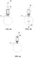
- Figs. 6a-6c illustrate vibration effects which can be minimised with the arrangement according to the invention.
- the rider-roll beam 18 comprising the rider roll 12 has been excited in the machine-directional rotary vibration the torsion centre 40 of which is above the beam 18.
- Fig. 6b shows a situation in which the torsion centre 40 of the rotary vibration is below the rider-roll beam and, equivalently, Fig. 6c shows the torsion centre 40 of the rotary vibration in the area of the cross section of the rider-roll beam 18.
- the arrangement according to the invention can affect all these different modes of vibration.
- Fig. 7 shows a rider-roll beam 18 of the winding apparatus according to an embodiment of the invention fitted in the carriage 20.
- the connection has been implemented so that there are pins 110 at the ends of the rider-roll beam which are fitted via sleeves 120 to the carriage 20.
- the sleeves are of elastic and/or damping material, whereby they operate as the elastic and/or damping arrangement of the rider-roll beam 18.
- Fig. 8 illustrates the behaviour of vibration frequency f of a rider roll as a function of a reel diameter ⁇ .
- Dashed line 80 depicts a process according to prior art in which the reel diameter increases to a value ⁇ f .
- a peak f max of undesired vibration is located within an area determined by the reel size being wound, whereas by using the arrangement according to the invention said frequency peak f max can be displaced in an area outside the maximum size of reels being wound, as shown by curve 82.
Landscapes
- Winding Of Webs (AREA)
- Braking Arrangements (AREA)
- Rolls And Other Rotary Bodies (AREA)
Abstract
Description
- The invention relates to a winding apparatus of a fibrous web according to the preamble of
claim 1, which comprises at least one support element supporting a reel of its surface when winding which is movably supported to a support structure by control elements determining the path of the support element. - The invention also relates to a method for winding a fibrous web on a winding apparatus according to the preamble of
claim 12, which comprises at least one support element supporting a reel of its surface when winding, in which method, the reel being formed is supported of its surface by the support element and simultaneously a pre-determined support force applied to the reel is maintained. - As known from prior art, on the slitter-winder the machine reel is unwound and the wide web is slit in the slitting section of the slitter-winder into several narrower partial webs which are wound up on the winding section around winding spools, such as cores, into customer reels. When customer reels made simultaneously of each partial web are completed, the slitter-winder is stopped and the reels i.e. the so-called set is removed from the machine. After this, the process is continued as the winding of a new set. These steps are repeated periodically until paper runs out of the machine reel, whereby the machine reel is replaced and the operation starts again as the winding of a new machine reel. A partial-web winder can be a winder of carrier-roll type in which the partial web reels are wound supported by carrier rolls by means of a winding nip between the forming web reel and a second carrier roll typically supported by a rider roll.
- In winding, e.g. when winding a paper web on the slitter-winder, intensive vibrations occur with certain paper grades at the same reel rotation frequency ranges irrespective of the run speed of the slitter-winder. There usually are 1-3 of those vibration ranges, i.e. reel rotation frequency ranges at which intensive vibration occurs, depending on the final diameter of the reel. This intensive vibration produces winding broke, mechanical wear of the devices, even the detachment of the reel from the winding device and a decrease in the winding capacity, because the run speed has to be slowed down during winding. Specification
FI101283 - As partial web reels grow on the carrier-roll winding section, at least the rider roll is displaced determined by the diameter of the reels and, therefore, at least the rider roll arrangement is movably supported on the frame structure of the winding part. Also, slitter-winders are known from prior art which employ a carrier-roll winding section of variable geometry for winding partial rolls in which section one or both of the carrier rolls/sets of rolls carrying the reel are displaceable. On such variable-geometric slitter-winders, the horizontal location of the centre of the reel being formed depends on the position of the carrier rolls/sets of rolls in relation to each other and the diameter of the reel. Longitudinal successive cores are locked in place as a core array by a core locking device located at both ends.
- Support elements in contact with the reel (or reels) being wound are exposed to dynamic load produced by the rotating reel. Particularly on a winder of carrier-roll type, dynamic load is created which incurs vibration excited by partial web reels being wound particularly in a rider roll of the carrier-roll winder and in a rider-roll beam on which the rider roll is supported. It is also typical of the process that the diameter of the reel being wound affects the vibration of the rider roll. Then, the vibration conditions change as the winding proceeds. A problem is the vibratory motion of the rider-roll beam substantially horizontal (machine-directional) in relation to the longitudinal axis.
- The rider roll particularly has a set of normal modes at least two of which are such of their form that in a resonance situation the motion of the support structure is substantially rotating in the longitudinal direction of the support structure of the rider roll in relation to the support of the support structure.
- The design of a rider roll of a slitter-winder aims at a stable construction enduring dynamic load. In practice, an arrangement is commonly used in which rider roll segments are supported in a relatively rigid rider-roll beam. The rider-roll beam is moved with hydraulic cylinders along guides fastened in the frame. Both the guides and the cylinders are located in the vicinity of the beam ends.
- Specification
US4165843 describes a carrier-roll winding device the rider-roll beam of which is hung on chains and at the opposite ends of the rider-roll beam are constructed two dampers fed with compressed air made as cylinder-piston apparatuses which press against the frame by means of friction surfaces at the ends of their piston rods. In such a support, the position of the rider-roll beam and the rider roll is very weakly controlled and, inter alia, the control possibilities of the nip force of the rider roll are practically almost nonexistent. - Specification
FI20055039 - Even though the above arrangements are advantageous as such, now there are requirements to improve the vibration characteristics and operation of the winding apparatus of a fibrous web. Therefore, the object of this invention is particularly to improve the prior art prevailing in the field by introducing such a winding apparatus of a fibrous web and a method for winding the fibrous web on the winding apparatus that better than previously operation and run possibilities can be implemented.
- The winding apparatus of a fibrous web according to the invention comprises at least one support element supporting a reel of its surface when winding which is movably supported to a support structure by control elements determining the path of the support element. The objects of the invention are achieved mainly by a winding apparatus which comprises a damping arrangement which enables changing the elasticity and/or damping of the support element in two different directions during the use of the winding apparatus and/or the motion of the support element.
- This provides, inter alia, that the vibration characteristics of the support element can always be adjusted such in both the vertical and machine direction that the reel being wound does not considerably excite the vibration of the support element. Particularly, the elastic and/or damping arrangement according to the invention substantially affects the machine-directional vibration. Elasticity and/or damping can be changed according to the invention during winding.
- Advantageously, the damping arrangement comprises an arrangement converting vibration energy to heat by means of friction fitted between said support element and the frame part of the winding apparatus. This provides an arrangement which damps vibrations effectively and which is very quick to adjust. The arrangement converting vibration energy to heat by means of friction advantageously comprises an adjustable brake apparatus.
- The winding apparatus advantageously comprises an apparatus determining the vibration frequency and/or amplitude of the support element which is arranged to supply a control signal for controlling the operation of the damping arrangement during the use of the winding apparatus and/or the motion of the support element. Then, it is possible to ensure that the vibration characteristics of the support element are accurate in each run situation.
- The winding apparatus advantageously comprises a measurement and feedback apparatus which is arranged to control the winding according to a pre-determined model. The measurement and feedback apparatus can further be arranged to control the winding according to pre-determined mode value points. The winding apparatus can advantageously comprise an adaptive measurement and feedback apparatus for controlling the damping arrangement.
- According to an embodiment, the elasticity and/or damping of the support element have been arranged changeable on the winding apparatus as a function of the diameter of the reel being wound. This produces an advantageous end result, because the vibration frequency of the reel is in a certain way dependent of the reel diameter. Also this way, the arrangement according to the invention provides an advantageous effect on the operation of the winding apparatus.
- The support element of the winding apparatus can be arranged to simultaneously support several parallel reels being wound on the winding apparatus in connection with the slitter-winder of a fibrous web. Then, the support element comprises a rider roll and the winding apparatus is advantageously a carrier-roll winder.
- The brake apparatus according to an embodiment of the invention comprises at least one disc brake caliper in contact with the support element, whereby in the frame of the winding apparatus is fitted on the path of the support element at least one brake bar so that in all positions of the support element the brake bar is in operational contact with the disc brake caliper.
- According to an embodiment, changing the elasticity and/or damping of the support element in two different directions during the use of the winding apparatus and/or the motion of the support element enables that the direction of the plane of the brake bar substantially diverges from the cross direction of the winding apparatus i.e. the longitudinal direction of the support element.
- The operation of the damping arrangement according to the invention can be further enhanced by fitting the damping arrangement between the support element and the frame part of the winding apparatus so that the connection to the frame part is outside a longitudinal torsion centre of the support element. Then, the effective distance of the dynamic force in vibration damping is greater and the damping is more effective.
- According to a further embodiment of the invention, the support element supporting the reel of its surface is fitted with an elastic and/or damping connection to a guide arrangement controlling its motion. In this embodiment, the connection comprises parts fitted within each other which are separated by a close-tolerance elastic/damping element.
- In the method for winding a fibrous web on the winding apparatus according to the invention, which comprises at least one support element supporting a reel of its surface when winding, the reel being formed is supported by the support element of its surface and simultaneously a pre-determined support force applied to the reel is maintained. It is mainly characteristic of the invention that during winding the vibration characteristics and/or damping of the support element are adjusted by changing the elasticity and/or damping of the support element in two different directions.
- The method can be further enhanced so that the vibration frequency and/or amplitude of the support element are determined during winding and that the vibration characteristics and/or damping of the support element are adjusted based on the vibration frequency and/or amplitude of the support element.
- According to an embodiment, the vibration characteristics and/or damping of the support element are adjusted based on the rotation frequency of the reel so that, when the rotation frequency of the reel approaches a reel rotation frequency range at which intense vibration occurs, the support rigidity of the support element is changed so that the natural vibration frequency of the support element and the reels differs from the prevailing excitation frequency of the reel. This way, it is possible to avoid a situation in which the natural frequency of the support element and the reels would be too close to the rotation frequency of the reel, whereby exciting the vibration of the support element and the reels is prevented with active adjustment without requiring to change the rotation speed of the winding apparatus.
- The elasticity and/or damping of the support element are changed with a damping arrangement which is fitted between the support element and the frame part of the winding apparatus so that the connection of the damping arrangement to the frame part is outside the longitudinal torsion centre of the support element, whereby the vibration force is conveyed to the frame outside the torsion centre.
- The elasticity and/or damping of the support element are changed according to an embodiment in the damping arrangement by converting vibration energy to heat by means of friction. Then, the damping arrangement advantageously comprises a brake apparatus in which there is at least one disc brake caliper in contact with the support element, and at least one brake bar fitted in the frame of the winding apparatus on the path of the support element so that in all positions of the support element the disc brake caliper moves on the brake bar during winding.
- According to an embodiment, the brake power of the brake apparatus is continuously adjusted based on the rotation frequency of the reel. According to another embodiment, the brake power of the brake apparatus is continuously adjusted based on the vibration measurement of the support element.
- The brake apparatus is run according to an embodiment periodically so that the brake apparatus is either in a substantially locked mode or a substantially unlocked mode and that, in the method, the periods and/or the ratio of the periods of these modes are adjusted.
- The invention and its operation will now be described with reference to the accompanying schematic figures in which
-
Fig. 1 shows a winding apparatus according to an embodiment of the invention, -
Fig. 2 shows a top view of the embodiment ofFig. 1 , -
Fig. 3 shows a detail A ofFig. 1 , -
Fig. 4 shows a control system of the embodiment ofFig. 1 , -
Fig. 5 shows a winding apparatus according to another embodiment of the invention, -
Figs. 6a-c show various modes of vibration of a rider-roll beam, -
Fig. 7 shows a rider-roll beam of a winding apparatus according to a further embodiment of the invention, and -
Fig. 8 schematically shows the effect of the arrangement according to the invention. -
Fig. 1 shows a carrier-roll winder 10 of a slitter-winder of a fibrous web, in which the fibrous web cut into partial webs W is wound intofibrous web reels 11 supported by support elements, in this embodiment carrier rolls 13, 14 and arider roll 12. Here, the first of the carrier rolls of thewinder 10 is anormal roll 14 and the second is a set of belt rolls 13. The carrier-roll winder 10 also comprises aframe 16 operating as the support structure of its parts. The carrier rolls 13, 14 are typically supported rotatably in the frame. In some embodiments, the second of the carrier rolls 14 is supported to the frame so that its position is changeable. Similarly, the position of therider roll 12 is changeable. Therider roll 12 is supported to a rider-roll beam 18 which is connected from its both ends to acarriage 20. Again, thecarriage 20 is supported to guides 22. The guides operate in the use of the winder as control elements determining the path of therider roll 12. During the operation of the winder, the carrier rolls 13, 14 and therider roll 12 support thereel 11 of its surface. The position of therider roll 12 and the force produced by it in the fibrous-web reel 11 is implemented by means of apower unit 24, such as a hydraulic cylinder. The hydraulic cylinder is supported of its one end on theframe 16, from its other end on thecarriage 20 of the rider roll.Fig. 2 shows a top view of the parts connected to therider roll 12 of the carrier-roll winder ofFig. 1 . - Referring to
Figs. 1 and 2 according to the invention, the winding apparatus comprises a dampingarrangement 30 which enables changing the elasticity and/or damping of thesupport element 13 in two different directions/degrees of freedom during the use of the winding apparatus and/or the motion of the support element. The damping arrangement and its operation will next be described by way of examples in the windingapparatus 10 shown byFig. 1 . The support element, which here comprises mainly therider roll 12 and the rider-roll beam 18, is in contact with theframe 16 via the dampingarrangement 30 which is connected to the frame via anarrangement 32 allowing a limitable motion. The motion is limitable so that with thearrangement 32 the damping arrangement allows the motion of the support element in relation to the frame but either so that the vibration energy of the support element is changed to heat by means of friction when it moves in relation to the frame or so that the arrangement is periodically kept in a locked mode or a substantially unlocked mode, whereby the periods and/or the ratio of the periods of these modes are adjusted. Also a combination of all these modes can be applicable in some cases. - In the damping arrangement, changing the elasticity and/or damping of the support element in two different directions is provided in the embodiment of
Fig. 1 so that thearrangement 32 allowing the limitable motion of the dampingarrangement 30 comprises an adjustable brake apparatus fitted in a certain way which can also be designated withreference number 32 in the following. - The
brake apparatus 32 comprises adisc brake caliper 34 connected to the rider-roll beam 18 which operates like a disc brake conventional as such. To theframe 16 of the winding apparatus is fitted on the path of the brake caliper, and thus also of the rider-roll beam 18, at least onebrake bar 36. In the embodiment ofFig. 1 , the brake bar is fitted substantially parallel to theguides 22. It is fundamental that, in all positions of the rider-roll beam 18, thebrake bar 36 is in operational contact with the disc brake caliper, in more detail within thedisc brake caliper 34 at the range ofbrake shoes 38. - The brake apparatus has substantially two degrees of freedom by which changing the elasticity and/or damping of the support element is provided in two different directions. In the brake apparatus, motion between the
brake bar 36 and the rider-roll beam can occur in the direction allowed by the brake apparatus, i.e. substantially in a plane determined by the brake discs. The plane X-Y determined by thebrake discs 38, and thus also by thebrake bar 36, is in a position substantially diverging from the longitudinal direction of the rider-roll beam 18, most advantageously almost perpendicular in relation to the rider-roll beam, whereby the brake can be made to affect the damping of vibration in a direction substantially diverging from both the vertical direction Y and the cross direction which is also the longitudinal direction of the rider-roll beam. A direction substantially diverging from the longitudinal direction of the rider-roll beam is advantageously the machine direction X. The rigidity of the actual rider-roll beam 18 and therider roll 12 and theframe 16 is so great that the motion caused by dynamic load applied to the rider roll, i.e. vibration, substantially conveys to the brake apparatus. In the brake apparatus, the elasticity and/or damping of the rider-roll beam 18 and the rider roll are thus changed by converting the motion and vibration energy to heat by means of friction. -
Fig. 1 further shows byreference number 40 the longitudinal torsion centre of the support apparatus for a certain construction. According to the invention, the dampingarrangement 30 is fitted between the support element and theframe 16 to connect to theframe 16 at acertain distance 42 from the torsion centre. This arrangement affects the rigidity of the support element extremely effectively and the continuous adjustment of the rigidity change during operation reacts very effectively in the control of the brake apparatus of the damping system. The primary reason is that the most problematic mode of vibration of the rider-roll beam 18 in practice is rotary vibration shown with a curved arrow inFig. 1 . The distance of the torsion centre is advantageously at least 300 mm, but is can also be even 1,000 mm. - The
brake apparatus 32 is advantageously arranged so that it connects the rider-roll beam 18 directly to theframe 16, whereby an additional support point is arranged for the support the support point of which is different from the support points of thecarriage 20 to theguides 22. This minimises the elasticity of the possible rider-roll beam, carriage and guides. - Even though not shown in
Fig. 1 , it is evident that there can be several brake apparatuses at both ends. When e.g. implemented with two brake apparatuses, the first brake apparatus then affects the machine-directional vibration and the second brake apparatus affects the vertical vibration. Furthermore, it is advantageous from the viewpoint of damping vibration to arrange a damping arrangement, in addition to the ends or alternatively, to such a point in the rider-roll beam 18 in which the vibration amplitude is at its highest, such as in the case of the first deflection form in the middle of the beam span. -
Fig. 3 shows a detail A ofFig. 2 in which a plane X'-Y determined by a brake disc 38', and thus also by a brake bar 36', is in a position substantially diverging from the longitudinal direction of the rider-roll beam 18. Even in such an arrangement, the two degrees of freedom of the brake apparatus in the plane X'-Y provide the active damping of vibration in both the vertical direction Y and the machine direction X. - The method according to the invention will next be described referring to
Fig. 4 . The windingapparatus 10 comprises an apparatus determining the vibration frequency and/or amplitude of the support element, here therider roll 12, which is arranged to supply a control signal for controlling the operation of the damping arrangement during the use of the winding apparatus and/or the motion of the support element. Said apparatus comprises a vibration and/orforce transducer 52 in the connection of the rider-roll beam 18 and thepower unit 24. Thetransducer 52 is connected to acontrol system 50. By means of thetransducer 52, the vibration of therider roll 18 and the nip force applied by it to the fibrous-web reel 11 are registered. The arrangement also comprises an arrangement for determining the diameter of thereel 11 which here takes place indirectly by means of a position sensor 54 in connection with thepower unit 24. - According to an embodiment of the invention, the elasticity and/or damping of the support element, here the
rider roll 12 and the rider-roll beam 18, are arranged changeable as a function of the diameter of thereel 11 being wound on the winding apparatus. In the winding event, the diameter of the reel is determined substantially continuously and the brake power of thebrake apparatus 30 is controlled based on the reel diameter. Then, in the system are saved the empirical vibration characteristics of different fibrous web grades and run modes with different reel diameters. By controlling thebrake apparatus 30 based on the diameter data, the winding apparatus is used so that the natural frequency of the support element is changed by using the brake apparatus such that it is not the same as the prevailing rotation frequency of the reel. - Depending on its characteristics, the fibrous-web reel has certain known rotation frequencies on which particularly intensive vibration occurs. According to the invention, the winding apparatus is run so that the vibration characteristics and/or damping of the support element are adjusted based on the rotation frequency of the reel so that, when the rotation frequency of the reel approaches a reel rotation frequency range at which intense vibration occurs, the support rigidity of the support element is changed so that the natural vibration frequency of the support element and the reels differs from the prevailing excitation frequency of the reel. It is possible to determine this rotation frequency substantially real-time or utilise previous grade-specific measurements based on the reel diameter and apply to the method based on reel diameters. This way, there is no need to change the actual winding speed, as was described in e.g. specification
FI101283 - The
brake apparatus 30 of the embodiment ofFig. 3 can be controlled according to an embodiment of the invention to operate pulse-like. Then, the pulse frequency of the brake apparatus is controlled suitable such that the brake apparatus allows in practice a certain slow motion speed. An increase in the pulse frequency enables a quicker motion and a decrease in the frequency enables a lower motion speed. In practice, this is observed in the arrangement according to the invention as damped vibration. - The locked time of the brake apparatus is measured advantageously so that during it the tensions of the structure increase substantially less than enabled by their durability, whereby always when the brake apparatus is unlocked the forces are freed and the brake sets in a position determined by the position of the beam.
- In some cases, the brake apparatus can also be run so that there is certain light braking on as the winding proceeds, whereby vibration is converted to heat by means of friction continuously.
-
Fig. 5 shows another embodiment according to the invention with its basic parts corresponding the embodiment ofFig. 1 and its operating principle similar to the one of the apparatus inFig. 1 .Fig. 5 uses the reference numbers ofFig. 1 of corresponding elements. The embodiment described here differs from the embodiment ofFig. 1 so that thebrake bar 36 is divergent from the path of the rider-roll beam 18 so that the dampingarrangement 30 is fitted between the support element and theframe 16 to connect to theframe 16 at the changingdistance 42 from the torsion centre. In this embodiment, thedistance 42 increases in the direction of motion of therider roll 12 away from the carrier rolls 13, 14. This way, the rigidity of the rider-roll beam increases as the reel diameter increases. If the characteristics of the fibrous web, the winding apparatus or the implemented process so require, the above dependency can be the other way around. The embodiment ofFig. 5 can be further developed so that thedistance 42 is adjustable irrespective of the position of the rider-roll beam 18 e.g. by arranging the brake bar displaceable or rotatable around its one end. -
Figs. 6a-6c illustrate vibration effects which can be minimised with the arrangement according to the invention. InFig. 6a , the rider-roll beam 18 comprising therider roll 12 has been excited in the machine-directional rotary vibration thetorsion centre 40 of which is above thebeam 18.Fig. 6b shows a situation in which thetorsion centre 40 of the rotary vibration is below the rider-roll beam and, equivalently,Fig. 6c shows thetorsion centre 40 of the rotary vibration in the area of the cross section of the rider-roll beam 18. The arrangement according to the invention can affect all these different modes of vibration. -
Fig. 7 shows a rider-roll beam 18 of the winding apparatus according to an embodiment of the invention fitted in thecarriage 20. The connection has been implemented so that there arepins 110 at the ends of the rider-roll beam which are fitted viasleeves 120 to thecarriage 20. The sleeves are of elastic and/or damping material, whereby they operate as the elastic and/or damping arrangement of the rider-roll beam 18. -
Fig. 8 illustrates the behaviour of vibration frequency f of a rider roll as a function of a reel diameter ∅. Dashedline 80 depicts a process according to prior art in which the reel diameter increases to a value ∅f. In an arrangement according to known prior art, a peak fmax of undesired vibration is located within an area determined by the reel size being wound, whereas by using the arrangement according to the invention said frequency peak fmax can be displaced in an area outside the maximum size of reels being wound, as shown bycurve 82. - It should be noted that only a few of the most advantageous embodiments of the invention were described above. Thus, it is evident that the invention is not limited to the above embodiments, but it can be applied in many ways within the scope defined by the enclosed claims. In some embodiments, it is also possible to use instead of or in addition to the brake apparatus a technique based on eddy current or viscous damping in a way defined by the invention. It is also possible that features described in connection with different embodiments are used within the scope of the basic idea of the invention in connection with other embodiments and/or combine various units of the described features, if so required and technical possibilities for this existing.
Claims (15)
- A winding apparatus of a fibrous web, which comprises at least one support element supporting a reel of its surface when winding, which is movably supported to a support structure by control elements determining the path of the support element, characterised in that the winding apparatus comprises an elastic and/or damping arrangement which enables changing the elasticity and/or damping of the support element at least in two different directions/degrees of freedom during the use of the winding apparatus and/or the motion of the support element.
- A winding apparatus of a fibrous web according to claim 1, characterised in that the elastic and/or damping arrangement is arranged to affect the machine-directional vibration or the longitudinal rotary vibration of the support element.
- A winding apparatus of a fibrous web according to claim 1, characterised in that the elastic and/or damping arrangement is arranged for changing the elasticity and/or damping during winding or to affect in at least two translation and/or at least one rotation degrees of freedom.
- A winding apparatus of a fibrous web according to claim 1, characterised in that the damping arrangement comprises an arrangement converting vibration energy to heat by means of friction fitted between said support element and the frame part of the winding apparatus.
- A winding apparatus of a fibrous web according to claim 1, characterised in that the winding apparatus comprises an apparatus determining the vibration frequency and/or amplitude of the support element which is arranged to supply a control signal for controlling the operation of the damping arrangement during the use of the winding apparatus and/or the motion of the support element.
- A winding apparatus of a fibrous web according to claim 4, characterised in that the damping arrangement comprises power elements to compensate the effect of the damping arrangement substantially in the vertical direction.
- A winding apparatus of a fibrous web according to claim 1, characterised in that the winding apparatus comprises a measurement and feedback apparatus for controlling the damping arrangement.
- A winding apparatus of a fibrous web according to claim 1, characterised in that the elasticity and/or damping of the support element are arranged changeable as a function of the reel diameter being wound on the winding apparatus or in that the support element of the winding apparatus is arranged to simultaneously support several reels (11) being wound on the winding apparatus.
- A winding apparatus of a fibrous web according to claim 4, characterised in that the winding apparatus comprises at least one adjustable brake apparatus.
- A winding apparatus of a fibrous web according to claim 9, characterised in that the brake apparatus comprises at least one disc brake caliper in contact with the support element, and that in the frame of the winding apparatus is fitted on the path of the support element at least one brake bar so that in all positions of the support element the brake bar is in operational contact with the disc brake caliper and the direction of the plane of the brake bar substantially diverges from the cross direction of the winding apparatus or is substantially machine-directional.
- A winding apparatus of a fibrous web according to claim 4, characterised in that the damping arrangement is fitted between the support element and the frame part of the winding apparatus so that the connection to the frame part is outside a longitudinal torsion centre of the support element.
- A method for winding a fibrous web on a winding apparatus, which comprises at least one support element supporting a reel of its surface when winding, in which method, the reel being formed is supported by the support element of its surface and simultaneously a pre-determined support force applied to the reel is maintained, characterised in that during winding the vibration characteristics and/or damping of the support element are adjusted by changing the elasticity and/or damping of the support element in two different directions.
- A method according to claim 12, characterised in that the vibration frequency and/or amplitude of the support element are determined during winding and that the vibration characteristics and/or damping of the support element are adjusted based on the vibration frequency and/or amplitude of the support element or in that the vibration characteristics and/or damping of the support element are adjusted based on the rotation frequency of the reel so that, when the rotation frequency of the reel approaches a reel rotation frequency range at which intense vibration occurs, the support rigidity of the support element is changed so that the natural vibration frequency of the support element and the reels differs from the prevailing excitation frequency of the reel.
- A method according to claim 12, characterised in that the elasticity and/or damping of the support element are changed with a damping arrangement which is fitted between the support element and the frame part of the winding apparatus so that the connection to the frame part is outside a longitudinal torsion centre of the support element.
- A method according to claim 12, characterised in that the elasticity and/or damping of the support element are changed in the damping arrangement by converting vibration energy to heat by means of friction.
Applications Claiming Priority (1)
| Application Number | Priority Date | Filing Date | Title |
|---|---|---|---|
| FI20085602A FI123004B (en) | 2008-06-18 | 2008-06-18 | Apparatus for winding a fibrous web and a method for winding a fibrous web |
Publications (3)
| Publication Number | Publication Date |
|---|---|
| EP2135828A2 true EP2135828A2 (en) | 2009-12-23 |
| EP2135828A3 EP2135828A3 (en) | 2010-12-08 |
| EP2135828B1 EP2135828B1 (en) | 2018-05-23 |
Family
ID=39589365
Family Applications (1)
| Application Number | Title | Priority Date | Filing Date |
|---|---|---|---|
| EP09161640.9A Not-in-force EP2135828B1 (en) | 2008-06-18 | 2009-06-02 | Winding apparatus of fibrous web and method for winding fibrous web |
Country Status (2)
| Country | Link |
|---|---|
| EP (1) | EP2135828B1 (en) |
| FI (1) | FI123004B (en) |
Cited By (1)
| Publication number | Priority date | Publication date | Assignee | Title |
|---|---|---|---|---|
| CN111235758A (en) * | 2019-10-27 | 2020-06-05 | 惠州市金豪成无纺布有限公司 | Non-woven fabric processing device |
Citations (3)
| Publication number | Priority date | Publication date | Assignee | Title |
|---|---|---|---|---|
| US4165843A (en) | 1977-09-02 | 1979-08-28 | Jagenberg Werke Aktiengesellschaft | Apparatus for winding a web of material, especially paper |
| FI101283B (en) | 1996-10-29 | 1998-05-29 | Valmet Corp | Procedure for rolling a paper web |
| FI20055039A (en) | 2005-01-27 | 2006-07-28 | Metso Paper Inc | Method and apparatus for damping vibrations in a carrier roll type reel |
Family Cites Families (4)
| Publication number | Priority date | Publication date | Assignee | Title |
|---|---|---|---|---|
| DE3924612A1 (en) * | 1989-07-26 | 1991-01-31 | Jagenberg Ag | SUPPORT ROLLER REWINDING MACHINE FOR REWINDING MATERIALS |
| DE102005000003A1 (en) * | 2005-01-19 | 2006-07-20 | Voith Paper Patent Gmbh | King roll winding machine for rolling up a length of material like paper or cardboard has an on-load roller for pressing a winding roller into a winding bed |
| DE102006043628A1 (en) * | 2006-09-18 | 2008-03-27 | Voith Patent Gmbh | King roll winding machine for material web i.e. paper web or cardboard web, has press roller whose pressing force is controlled or regulated over handle corresponding to diameter of winding roller using damping device |
| DE102006043639A1 (en) * | 2006-09-18 | 2008-03-27 | Voith Patent Gmbh | winder |
-
2008
- 2008-06-18 FI FI20085602A patent/FI123004B/en not_active IP Right Cessation
-
2009
- 2009-06-02 EP EP09161640.9A patent/EP2135828B1/en not_active Not-in-force
Patent Citations (3)
| Publication number | Priority date | Publication date | Assignee | Title |
|---|---|---|---|---|
| US4165843A (en) | 1977-09-02 | 1979-08-28 | Jagenberg Werke Aktiengesellschaft | Apparatus for winding a web of material, especially paper |
| FI101283B (en) | 1996-10-29 | 1998-05-29 | Valmet Corp | Procedure for rolling a paper web |
| FI20055039A (en) | 2005-01-27 | 2006-07-28 | Metso Paper Inc | Method and apparatus for damping vibrations in a carrier roll type reel |
Cited By (1)
| Publication number | Priority date | Publication date | Assignee | Title |
|---|---|---|---|---|
| CN111235758A (en) * | 2019-10-27 | 2020-06-05 | 惠州市金豪成无纺布有限公司 | Non-woven fabric processing device |
Also Published As
| Publication number | Publication date |
|---|---|
| FI123004B (en) | 2012-09-28 |
| FI20085602A0 (en) | 2008-06-18 |
| FI20085602A (en) | 2009-12-19 |
| EP2135828A3 (en) | 2010-12-08 |
| EP2135828B1 (en) | 2018-05-23 |
Similar Documents
| Publication | Publication Date | Title |
|---|---|---|
| FI118961B (en) | A method of damping vibrations by scrollers | |
| EP1056666B1 (en) | Method and apparatus in reeling of a web | |
| EP2027048B1 (en) | Arrangement for attenuating vibration of a roll assembly | |
| JP4329904B2 (en) | Material web winder | |
| EP2108606B1 (en) | Carrier-roll winder and method for using carrier-roll winder | |
| EP2653422B1 (en) | Method and device for winding of fiber webs, especially of partial paper and board webs | |
| EP2135828B1 (en) | Winding apparatus of fibrous web and method for winding fibrous web | |
| JP2002528364A (en) | Method and apparatus for controlling reel structure | |
| EP1056665B1 (en) | Pressure roller reel-up and method therefor | |
| FI118258B (en) | Method and apparatus for attenuating vibration in a wheelchair of carrier type | |
| EP1037839B1 (en) | Method in a treatment process of a paper web and treatment device for a paper web | |
| EP2813451A1 (en) | A two-drum winder | |
| US20100187349A1 (en) | In or relating to creels | |
| CN101652199B (en) | Dual pivot ironing roll | |
| EP2408699B1 (en) | Roll assembly for a fibre-web machine and method of attenuating vibration of a fibre- web machine roll | |
| FI122033B (en) | Rolling arrangement and roller cutting machine in a fiber web machine | |
| EP2673227B1 (en) | Arrangement for dampening the vibration of an apparatus assembly of a fibrous web machine and a method for dampening vibration at an apparatus assembly of a fibrous web machine | |
| EP2813452B1 (en) | A two-drum winder and a method of operating a two-drum winder | |
| EP2749513A1 (en) | Method of operating a slitter-winder for winding fiber webs | |
| FI122719B (en) | Fiber web winder winding section and method for modernizing fiber web winder winding section | |
| EP2711321B1 (en) | Loading roll for a reeling shaft of a reel-up for a fiber web | |
| FI127119B (en) | A system for damping vibrations in the nip of a fiber web machine | |
| EP2916030B1 (en) | Adjustable tuned mass damper | |
| EP2610405A1 (en) | Method in a finishing device of a fiber web machine | |
| WO2012056112A1 (en) | Roll support arrangement of a fiber web machine and a partial web winder of a fiber web slitter winder |
Legal Events
| Date | Code | Title | Description |
|---|---|---|---|
| PUAI | Public reference made under article 153(3) epc to a published international application that has entered the european phase |
Free format text: ORIGINAL CODE: 0009012 |
|
| AK | Designated contracting states |
Kind code of ref document: A2 Designated state(s): AT BE BG CH CY CZ DE DK EE ES FI FR GB GR HR HU IE IS IT LI LT LU LV MC MK MT NL NO PL PT RO SE SI SK TR |
|
| PUAL | Search report despatched |
Free format text: ORIGINAL CODE: 0009013 |
|
| AK | Designated contracting states |
Kind code of ref document: A3 Designated state(s): AT BE BG CH CY CZ DE DK EE ES FI FR GB GR HR HU IE IS IT LI LT LU LV MC MK MT NL NO PL PT RO SE SI SK TR |
|
| 17P | Request for examination filed |
Effective date: 20110512 |
|
| RAP1 | Party data changed (applicant data changed or rights of an application transferred) |
Owner name: VALMET TECHNOLOGIES, INC. |
|
| 17Q | First examination report despatched |
Effective date: 20170316 |
|
| REG | Reference to a national code |
Ref country code: DE Ref legal event code: R079 Ref document number: 602009052410 Country of ref document: DE Free format text: PREVIOUS MAIN CLASS: B65H0018140000 Ipc: B65H0018160000 |
|
| RIC1 | Information provided on ipc code assigned before grant |
Ipc: B65H 18/22 20060101ALI20170928BHEP Ipc: B65H 18/16 20060101AFI20170928BHEP |
|
| GRAP | Despatch of communication of intention to grant a patent |
Free format text: ORIGINAL CODE: EPIDOSNIGR1 |
|
| INTG | Intention to grant announced |
Effective date: 20171207 |
|
| GRAS | Grant fee paid |
Free format text: ORIGINAL CODE: EPIDOSNIGR3 |
|
| GRAA | (expected) grant |
Free format text: ORIGINAL CODE: 0009210 |
|
| AK | Designated contracting states |
Kind code of ref document: B1 Designated state(s): AT BE BG CH CY CZ DE DK EE ES FI FR GB GR HR HU IE IS IT LI LT LU LV MC MK MT NL NO PL PT RO SE SI SK TR |
|
| REG | Reference to a national code |
Ref country code: GB Ref legal event code: FG4D |
|
| REG | Reference to a national code |
Ref country code: CH Ref legal event code: EP |
|
| REG | Reference to a national code |
Ref country code: IE Ref legal event code: FG4D |
|
| REG | Reference to a national code |
Ref country code: AT Ref legal event code: REF Ref document number: 1001358 Country of ref document: AT Kind code of ref document: T Effective date: 20180615 |
|
| REG | Reference to a national code |
Ref country code: DE Ref legal event code: R096 Ref document number: 602009052410 Country of ref document: DE |
|
| REG | Reference to a national code |
Ref country code: NL Ref legal event code: MP Effective date: 20180523 |
|
| REG | Reference to a national code |
Ref country code: LT Ref legal event code: MG4D |
|
| PG25 | Lapsed in a contracting state [announced via postgrant information from national office to epo] |
Ref country code: ES Free format text: LAPSE BECAUSE OF FAILURE TO SUBMIT A TRANSLATION OF THE DESCRIPTION OR TO PAY THE FEE WITHIN THE PRESCRIBED TIME-LIMIT Effective date: 20180523 Ref country code: LT Free format text: LAPSE BECAUSE OF FAILURE TO SUBMIT A TRANSLATION OF THE DESCRIPTION OR TO PAY THE FEE WITHIN THE PRESCRIBED TIME-LIMIT Effective date: 20180523 Ref country code: FI Free format text: LAPSE BECAUSE OF FAILURE TO SUBMIT A TRANSLATION OF THE DESCRIPTION OR TO PAY THE FEE WITHIN THE PRESCRIBED TIME-LIMIT Effective date: 20180523 Ref country code: NO Free format text: LAPSE BECAUSE OF FAILURE TO SUBMIT A TRANSLATION OF THE DESCRIPTION OR TO PAY THE FEE WITHIN THE PRESCRIBED TIME-LIMIT Effective date: 20180823 Ref country code: BG Free format text: LAPSE BECAUSE OF FAILURE TO SUBMIT A TRANSLATION OF THE DESCRIPTION OR TO PAY THE FEE WITHIN THE PRESCRIBED TIME-LIMIT Effective date: 20180823 Ref country code: SE Free format text: LAPSE BECAUSE OF FAILURE TO SUBMIT A TRANSLATION OF THE DESCRIPTION OR TO PAY THE FEE WITHIN THE PRESCRIBED TIME-LIMIT Effective date: 20180523 |
|
| PG25 | Lapsed in a contracting state [announced via postgrant information from national office to epo] |
Ref country code: GR Free format text: LAPSE BECAUSE OF FAILURE TO SUBMIT A TRANSLATION OF THE DESCRIPTION OR TO PAY THE FEE WITHIN THE PRESCRIBED TIME-LIMIT Effective date: 20180824 Ref country code: LV Free format text: LAPSE BECAUSE OF FAILURE TO SUBMIT A TRANSLATION OF THE DESCRIPTION OR TO PAY THE FEE WITHIN THE PRESCRIBED TIME-LIMIT Effective date: 20180523 Ref country code: HR Free format text: LAPSE BECAUSE OF FAILURE TO SUBMIT A TRANSLATION OF THE DESCRIPTION OR TO PAY THE FEE WITHIN THE PRESCRIBED TIME-LIMIT Effective date: 20180523 Ref country code: NL Free format text: LAPSE BECAUSE OF FAILURE TO SUBMIT A TRANSLATION OF THE DESCRIPTION OR TO PAY THE FEE WITHIN THE PRESCRIBED TIME-LIMIT Effective date: 20180523 |
|
| REG | Reference to a national code |
Ref country code: AT Ref legal event code: MK05 Ref document number: 1001358 Country of ref document: AT Kind code of ref document: T Effective date: 20180523 |
|
| PG25 | Lapsed in a contracting state [announced via postgrant information from national office to epo] |
Ref country code: CZ Free format text: LAPSE BECAUSE OF FAILURE TO SUBMIT A TRANSLATION OF THE DESCRIPTION OR TO PAY THE FEE WITHIN THE PRESCRIBED TIME-LIMIT Effective date: 20180523 Ref country code: SK Free format text: LAPSE BECAUSE OF FAILURE TO SUBMIT A TRANSLATION OF THE DESCRIPTION OR TO PAY THE FEE WITHIN THE PRESCRIBED TIME-LIMIT Effective date: 20180523 Ref country code: EE Free format text: LAPSE BECAUSE OF FAILURE TO SUBMIT A TRANSLATION OF THE DESCRIPTION OR TO PAY THE FEE WITHIN THE PRESCRIBED TIME-LIMIT Effective date: 20180523 Ref country code: PL Free format text: LAPSE BECAUSE OF FAILURE TO SUBMIT A TRANSLATION OF THE DESCRIPTION OR TO PAY THE FEE WITHIN THE PRESCRIBED TIME-LIMIT Effective date: 20180523 Ref country code: DK Free format text: LAPSE BECAUSE OF FAILURE TO SUBMIT A TRANSLATION OF THE DESCRIPTION OR TO PAY THE FEE WITHIN THE PRESCRIBED TIME-LIMIT Effective date: 20180523 Ref country code: RO Free format text: LAPSE BECAUSE OF FAILURE TO SUBMIT A TRANSLATION OF THE DESCRIPTION OR TO PAY THE FEE WITHIN THE PRESCRIBED TIME-LIMIT Effective date: 20180523 Ref country code: AT Free format text: LAPSE BECAUSE OF FAILURE TO SUBMIT A TRANSLATION OF THE DESCRIPTION OR TO PAY THE FEE WITHIN THE PRESCRIBED TIME-LIMIT Effective date: 20180523 |
|
| REG | Reference to a national code |
Ref country code: CH Ref legal event code: PL |
|
| REG | Reference to a national code |
Ref country code: DE Ref legal event code: R097 Ref document number: 602009052410 Country of ref document: DE |
|
| PG25 | Lapsed in a contracting state [announced via postgrant information from national office to epo] |
Ref country code: IT Free format text: LAPSE BECAUSE OF FAILURE TO SUBMIT A TRANSLATION OF THE DESCRIPTION OR TO PAY THE FEE WITHIN THE PRESCRIBED TIME-LIMIT Effective date: 20180523 |
|
| REG | Reference to a national code |
Ref country code: BE Ref legal event code: MM Effective date: 20180630 |
|
| REG | Reference to a national code |
Ref country code: IE Ref legal event code: MM4A |
|
| PG25 | Lapsed in a contracting state [announced via postgrant information from national office to epo] |
Ref country code: MC Free format text: LAPSE BECAUSE OF FAILURE TO SUBMIT A TRANSLATION OF THE DESCRIPTION OR TO PAY THE FEE WITHIN THE PRESCRIBED TIME-LIMIT Effective date: 20180523 Ref country code: LU Free format text: LAPSE BECAUSE OF NON-PAYMENT OF DUE FEES Effective date: 20180602 |
|
| PLBE | No opposition filed within time limit |
Free format text: ORIGINAL CODE: 0009261 |
|
| STAA | Information on the status of an ep patent application or granted ep patent |
Free format text: STATUS: NO OPPOSITION FILED WITHIN TIME LIMIT |
|
| GBPC | Gb: european patent ceased through non-payment of renewal fee |
Effective date: 20180823 |
|
| PG25 | Lapsed in a contracting state [announced via postgrant information from national office to epo] |
Ref country code: FR Free format text: LAPSE BECAUSE OF NON-PAYMENT OF DUE FEES Effective date: 20180723 Ref country code: CH Free format text: LAPSE BECAUSE OF NON-PAYMENT OF DUE FEES Effective date: 20180630 Ref country code: LI Free format text: LAPSE BECAUSE OF NON-PAYMENT OF DUE FEES Effective date: 20180630 Ref country code: IE Free format text: LAPSE BECAUSE OF NON-PAYMENT OF DUE FEES Effective date: 20180602 |
|
| 26N | No opposition filed |
Effective date: 20190226 |
|
| PG25 | Lapsed in a contracting state [announced via postgrant information from national office to epo] |
Ref country code: SI Free format text: LAPSE BECAUSE OF FAILURE TO SUBMIT A TRANSLATION OF THE DESCRIPTION OR TO PAY THE FEE WITHIN THE PRESCRIBED TIME-LIMIT Effective date: 20180523 Ref country code: BE Free format text: LAPSE BECAUSE OF NON-PAYMENT OF DUE FEES Effective date: 20180630 |
|
| PG25 | Lapsed in a contracting state [announced via postgrant information from national office to epo] |
Ref country code: GB Free format text: LAPSE BECAUSE OF NON-PAYMENT OF DUE FEES Effective date: 20180823 |
|
| PG25 | Lapsed in a contracting state [announced via postgrant information from national office to epo] |
Ref country code: MT Free format text: LAPSE BECAUSE OF NON-PAYMENT OF DUE FEES Effective date: 20180602 |
|
| PG25 | Lapsed in a contracting state [announced via postgrant information from national office to epo] |
Ref country code: TR Free format text: LAPSE BECAUSE OF FAILURE TO SUBMIT A TRANSLATION OF THE DESCRIPTION OR TO PAY THE FEE WITHIN THE PRESCRIBED TIME-LIMIT Effective date: 20180523 |
|
| PG25 | Lapsed in a contracting state [announced via postgrant information from national office to epo] |
Ref country code: PT Free format text: LAPSE BECAUSE OF FAILURE TO SUBMIT A TRANSLATION OF THE DESCRIPTION OR TO PAY THE FEE WITHIN THE PRESCRIBED TIME-LIMIT Effective date: 20180523 Ref country code: HU Free format text: LAPSE BECAUSE OF FAILURE TO SUBMIT A TRANSLATION OF THE DESCRIPTION OR TO PAY THE FEE WITHIN THE PRESCRIBED TIME-LIMIT; INVALID AB INITIO Effective date: 20090602 |
|
| PG25 | Lapsed in a contracting state [announced via postgrant information from national office to epo] |
Ref country code: MK Free format text: LAPSE BECAUSE OF NON-PAYMENT OF DUE FEES Effective date: 20180523 Ref country code: CY Free format text: LAPSE BECAUSE OF FAILURE TO SUBMIT A TRANSLATION OF THE DESCRIPTION OR TO PAY THE FEE WITHIN THE PRESCRIBED TIME-LIMIT Effective date: 20180523 |
|
| PG25 | Lapsed in a contracting state [announced via postgrant information from national office to epo] |
Ref country code: IS Free format text: LAPSE BECAUSE OF FAILURE TO SUBMIT A TRANSLATION OF THE DESCRIPTION OR TO PAY THE FEE WITHIN THE PRESCRIBED TIME-LIMIT Effective date: 20180923 |
|
| PGFP | Annual fee paid to national office [announced via postgrant information from national office to epo] |
Ref country code: DE Payment date: 20200618 Year of fee payment: 12 |
|
| REG | Reference to a national code |
Ref country code: DE Ref legal event code: R119 Ref document number: 602009052410 Country of ref document: DE |
|
| PG25 | Lapsed in a contracting state [announced via postgrant information from national office to epo] |
Ref country code: DE Free format text: LAPSE BECAUSE OF NON-PAYMENT OF DUE FEES Effective date: 20220101 |