EP2135726A2 - Verfahren und Vorrichtung zum Einsetzen eines Vorformlings in und zur Entnahme einer Flasche aus einer Blasmaschine - Google Patents
Verfahren und Vorrichtung zum Einsetzen eines Vorformlings in und zur Entnahme einer Flasche aus einer Blasmaschine Download PDFInfo
- Publication number
- EP2135726A2 EP2135726A2 EP09158158A EP09158158A EP2135726A2 EP 2135726 A2 EP2135726 A2 EP 2135726A2 EP 09158158 A EP09158158 A EP 09158158A EP 09158158 A EP09158158 A EP 09158158A EP 2135726 A2 EP2135726 A2 EP 2135726A2
- Authority
- EP
- European Patent Office
- Prior art keywords
- mold carrier
- mold
- carrier
- wheel
- actuating means
- Prior art date
- Legal status (The legal status is an assumption and is not a legal conclusion. Google has not performed a legal analysis and makes no representation as to the accuracy of the status listed.)
- Granted
Links
- 238000007664 blowing Methods 0.000 title claims abstract description 24
- 238000000034 method Methods 0.000 title claims abstract description 12
- 239000000969 carrier Substances 0.000 claims abstract description 18
- 238000003780 insertion Methods 0.000 claims abstract description 15
- 230000037431 insertion Effects 0.000 claims abstract description 15
- 238000000071 blow moulding Methods 0.000 claims description 26
- 238000010438 heat treatment Methods 0.000 description 7
- 238000012546 transfer Methods 0.000 description 6
- 238000001816 cooling Methods 0.000 description 3
- 239000000110 cooling liquid Substances 0.000 description 3
- 239000000498 cooling water Substances 0.000 description 3
- 230000008901 benefit Effects 0.000 description 2
- 238000013461 design Methods 0.000 description 2
- 230000003993 interaction Effects 0.000 description 2
- 238000012545 processing Methods 0.000 description 2
- 230000009471 action Effects 0.000 description 1
- 238000010924 continuous production Methods 0.000 description 1
- 239000011521 glass Substances 0.000 description 1
- 239000007788 liquid Substances 0.000 description 1
- 238000012986 modification Methods 0.000 description 1
- 230000004048 modification Effects 0.000 description 1
- 238000003860 storage Methods 0.000 description 1
Images



Classifications
-
- B—PERFORMING OPERATIONS; TRANSPORTING
- B29—WORKING OF PLASTICS; WORKING OF SUBSTANCES IN A PLASTIC STATE IN GENERAL
- B29C—SHAPING OR JOINING OF PLASTICS; SHAPING OF MATERIAL IN A PLASTIC STATE, NOT OTHERWISE PROVIDED FOR; AFTER-TREATMENT OF THE SHAPED PRODUCTS, e.g. REPAIRING
- B29C49/00—Blow-moulding, i.e. blowing a preform or parison to a desired shape within a mould; Apparatus therefor
- B29C49/42—Component parts, details or accessories; Auxiliary operations
- B29C49/56—Opening, closing or clamping means
-
- B—PERFORMING OPERATIONS; TRANSPORTING
- B29—WORKING OF PLASTICS; WORKING OF SUBSTANCES IN A PLASTIC STATE IN GENERAL
- B29C—SHAPING OR JOINING OF PLASTICS; SHAPING OF MATERIAL IN A PLASTIC STATE, NOT OTHERWISE PROVIDED FOR; AFTER-TREATMENT OF THE SHAPED PRODUCTS, e.g. REPAIRING
- B29C49/00—Blow-moulding, i.e. blowing a preform or parison to a desired shape within a mould; Apparatus therefor
- B29C49/28—Blow-moulding apparatus
- B29C49/30—Blow-moulding apparatus having movable moulds or mould parts
- B29C49/36—Blow-moulding apparatus having movable moulds or mould parts rotatable about one axis
-
- B—PERFORMING OPERATIONS; TRANSPORTING
- B29—WORKING OF PLASTICS; WORKING OF SUBSTANCES IN A PLASTIC STATE IN GENERAL
- B29C—SHAPING OR JOINING OF PLASTICS; SHAPING OF MATERIAL IN A PLASTIC STATE, NOT OTHERWISE PROVIDED FOR; AFTER-TREATMENT OF THE SHAPED PRODUCTS, e.g. REPAIRING
- B29C49/00—Blow-moulding, i.e. blowing a preform or parison to a desired shape within a mould; Apparatus therefor
- B29C49/42—Component parts, details or accessories; Auxiliary operations
- B29C49/4205—Handling means, e.g. transfer, loading or discharging means
- B29C49/42093—Transporting apparatus, e.g. slides, wheels or conveyors
- B29C49/42095—Rotating wheels or stars
-
- B—PERFORMING OPERATIONS; TRANSPORTING
- B29—WORKING OF PLASTICS; WORKING OF SUBSTANCES IN A PLASTIC STATE IN GENERAL
- B29C—SHAPING OR JOINING OF PLASTICS; SHAPING OF MATERIAL IN A PLASTIC STATE, NOT OTHERWISE PROVIDED FOR; AFTER-TREATMENT OF THE SHAPED PRODUCTS, e.g. REPAIRING
- B29C49/00—Blow-moulding, i.e. blowing a preform or parison to a desired shape within a mould; Apparatus therefor
- B29C49/42—Component parts, details or accessories; Auxiliary operations
- B29C49/78—Measuring, controlling or regulating
-
- B—PERFORMING OPERATIONS; TRANSPORTING
- B29—WORKING OF PLASTICS; WORKING OF SUBSTANCES IN A PLASTIC STATE IN GENERAL
- B29C—SHAPING OR JOINING OF PLASTICS; SHAPING OF MATERIAL IN A PLASTIC STATE, NOT OTHERWISE PROVIDED FOR; AFTER-TREATMENT OF THE SHAPED PRODUCTS, e.g. REPAIRING
- B29C49/00—Blow-moulding, i.e. blowing a preform or parison to a desired shape within a mould; Apparatus therefor
- B29C49/42—Component parts, details or accessories; Auxiliary operations
- B29C49/48—Moulds
- B29C49/4823—Moulds with incorporated heating or cooling means
- B29C2049/4825—Moulds with incorporated heating or cooling means for cooling moulds or mould parts
- B29C2049/4833—Moulds with incorporated heating or cooling means for cooling moulds or mould parts the cooling means being connected to an external heat exchanger
-
- B—PERFORMING OPERATIONS; TRANSPORTING
- B29—WORKING OF PLASTICS; WORKING OF SUBSTANCES IN A PLASTIC STATE IN GENERAL
- B29C—SHAPING OR JOINING OF PLASTICS; SHAPING OF MATERIAL IN A PLASTIC STATE, NOT OTHERWISE PROVIDED FOR; AFTER-TREATMENT OF THE SHAPED PRODUCTS, e.g. REPAIRING
- B29C49/00—Blow-moulding, i.e. blowing a preform or parison to a desired shape within a mould; Apparatus therefor
- B29C49/42—Component parts, details or accessories; Auxiliary operations
- B29C49/78—Measuring, controlling or regulating
- B29C49/786—Temperature
- B29C2049/7861—Temperature of the preform
- B29C2049/7862—Temperature of the preform characterised by temperature values or ranges
-
- B—PERFORMING OPERATIONS; TRANSPORTING
- B29—WORKING OF PLASTICS; WORKING OF SUBSTANCES IN A PLASTIC STATE IN GENERAL
- B29C—SHAPING OR JOINING OF PLASTICS; SHAPING OF MATERIAL IN A PLASTIC STATE, NOT OTHERWISE PROVIDED FOR; AFTER-TREATMENT OF THE SHAPED PRODUCTS, e.g. REPAIRING
- B29C33/00—Moulds or cores; Details thereof or accessories therefor
- B29C33/20—Opening, closing or clamping
- B29C33/26—Opening, closing or clamping by pivotal movement
-
- B—PERFORMING OPERATIONS; TRANSPORTING
- B29—WORKING OF PLASTICS; WORKING OF SUBSTANCES IN A PLASTIC STATE IN GENERAL
- B29C—SHAPING OR JOINING OF PLASTICS; SHAPING OF MATERIAL IN A PLASTIC STATE, NOT OTHERWISE PROVIDED FOR; AFTER-TREATMENT OF THE SHAPED PRODUCTS, e.g. REPAIRING
- B29C49/00—Blow-moulding, i.e. blowing a preform or parison to a desired shape within a mould; Apparatus therefor
- B29C49/42—Component parts, details or accessories; Auxiliary operations
- B29C49/4205—Handling means, e.g. transfer, loading or discharging means
- B29C49/42069—Means explicitly adapted for transporting blown article
-
- B—PERFORMING OPERATIONS; TRANSPORTING
- B29—WORKING OF PLASTICS; WORKING OF SUBSTANCES IN A PLASTIC STATE IN GENERAL
- B29C—SHAPING OR JOINING OF PLASTICS; SHAPING OF MATERIAL IN A PLASTIC STATE, NOT OTHERWISE PROVIDED FOR; AFTER-TREATMENT OF THE SHAPED PRODUCTS, e.g. REPAIRING
- B29C49/00—Blow-moulding, i.e. blowing a preform or parison to a desired shape within a mould; Apparatus therefor
- B29C49/42—Component parts, details or accessories; Auxiliary operations
- B29C49/48—Moulds
- B29C49/4823—Moulds with incorporated heating or cooling means
-
- B—PERFORMING OPERATIONS; TRANSPORTING
- B29—WORKING OF PLASTICS; WORKING OF SUBSTANCES IN A PLASTIC STATE IN GENERAL
- B29C—SHAPING OR JOINING OF PLASTICS; SHAPING OF MATERIAL IN A PLASTIC STATE, NOT OTHERWISE PROVIDED FOR; AFTER-TREATMENT OF THE SHAPED PRODUCTS, e.g. REPAIRING
- B29C49/00—Blow-moulding, i.e. blowing a preform or parison to a desired shape within a mould; Apparatus therefor
- B29C49/42—Component parts, details or accessories; Auxiliary operations
- B29C49/56—Opening, closing or clamping means
- B29C49/5601—Mechanically operated, i.e. closing or opening of the mould parts is done by mechanic means
- B29C49/5602—Mechanically operated, i.e. closing or opening of the mould parts is done by mechanic means using cams
-
- B—PERFORMING OPERATIONS; TRANSPORTING
- B29—WORKING OF PLASTICS; WORKING OF SUBSTANCES IN A PLASTIC STATE IN GENERAL
- B29C—SHAPING OR JOINING OF PLASTICS; SHAPING OF MATERIAL IN A PLASTIC STATE, NOT OTHERWISE PROVIDED FOR; AFTER-TREATMENT OF THE SHAPED PRODUCTS, e.g. REPAIRING
- B29C49/00—Blow-moulding, i.e. blowing a preform or parison to a desired shape within a mould; Apparatus therefor
- B29C49/42—Component parts, details or accessories; Auxiliary operations
- B29C49/56—Opening, closing or clamping means
- B29C49/5601—Mechanically operated, i.e. closing or opening of the mould parts is done by mechanic means
- B29C49/5603—Mechanically operated, i.e. closing or opening of the mould parts is done by mechanic means using toggle mechanism
-
- B—PERFORMING OPERATIONS; TRANSPORTING
- B29—WORKING OF PLASTICS; WORKING OF SUBSTANCES IN A PLASTIC STATE IN GENERAL
- B29C—SHAPING OR JOINING OF PLASTICS; SHAPING OF MATERIAL IN A PLASTIC STATE, NOT OTHERWISE PROVIDED FOR; AFTER-TREATMENT OF THE SHAPED PRODUCTS, e.g. REPAIRING
- B29C49/00—Blow-moulding, i.e. blowing a preform or parison to a desired shape within a mould; Apparatus therefor
- B29C49/42—Component parts, details or accessories; Auxiliary operations
- B29C49/56—Opening, closing or clamping means
- B29C49/5607—Electrically operated, e.g. the closing or opening is done with an electrical motor direct drive
-
- B—PERFORMING OPERATIONS; TRANSPORTING
- B29—WORKING OF PLASTICS; WORKING OF SUBSTANCES IN A PLASTIC STATE IN GENERAL
- B29C—SHAPING OR JOINING OF PLASTICS; SHAPING OF MATERIAL IN A PLASTIC STATE, NOT OTHERWISE PROVIDED FOR; AFTER-TREATMENT OF THE SHAPED PRODUCTS, e.g. REPAIRING
- B29C49/00—Blow-moulding, i.e. blowing a preform or parison to a desired shape within a mould; Apparatus therefor
- B29C49/42—Component parts, details or accessories; Auxiliary operations
- B29C49/56—Opening, closing or clamping means
- B29C49/561—Characterised by speed, e.g. variable opening closing speed
-
- B—PERFORMING OPERATIONS; TRANSPORTING
- B29—WORKING OF PLASTICS; WORKING OF SUBSTANCES IN A PLASTIC STATE IN GENERAL
- B29C—SHAPING OR JOINING OF PLASTICS; SHAPING OF MATERIAL IN A PLASTIC STATE, NOT OTHERWISE PROVIDED FOR; AFTER-TREATMENT OF THE SHAPED PRODUCTS, e.g. REPAIRING
- B29C49/00—Blow-moulding, i.e. blowing a preform or parison to a desired shape within a mould; Apparatus therefor
- B29C49/42—Component parts, details or accessories; Auxiliary operations
- B29C49/64—Heating or cooling preforms, parisons or blown articles
- B29C49/6409—Thermal conditioning of preforms
- B29C49/6436—Thermal conditioning of preforms characterised by temperature differential
- B29C49/6445—Thermal conditioning of preforms characterised by temperature differential through the preform length
- B29C49/645—Thermal conditioning of preforms characterised by temperature differential through the preform length by cooling the neck
Definitions
- the present invention relates to a method for inserting a preform into and for removing a bottle from a blow molding machine.
- the blow molding machine has a multiplicity of two-part mold carriers arranged on a means of transport. The mold carriers can be opened to remove the bottle and closed again after inserting the preform.
- the invention relates to an apparatus for inserting a preform in and for removing a bottle from a blow molding machine.
- the blow molding machine has a plurality of transport means arranged, two-part mold carrier. A first part of the mold carrier and a second part of the mold carrier are pivotally connected to each other about a common axis.
- a blow molding machine is used in particular for stretch blow molding of preforms.
- the blow molding machine itself comprises at least one blow mold.
- blow molds are used, in which a preform with positive pressure inside the blow mold blown, ie, auskonturiert.
- the blow mold can be z. B. comprise two mold halves which are rotatably mounted about a common axis. By turning about this axis, the mold halves can be opened and closed, In the open mold halves can be used a preform or a blown bottle can be removed.
- the design of such a mold carrier is z. B. in the European patent EP 1 276 598 B1 disclosed.
- the U.S. Patent 4,313,720 discloses a system for the continuous production of plastic bottles in which preheated preforms are blown into a blow mold so as to give the desired shape to the desired bottle.
- the preforms are transferred to a rotatable blowing station which carries a plurality of mold carriers.
- Each of the blowing stations consists of a first part of a mold carrier and a second Part of a mold carrier.
- At the removal station of the bottle arranged in the direction of rotation of the mold carrier wheel part of the mold carrier can be pivoted away to facilitate the removal of the finished bottle.
- the object of the invention is to provide a method by which the insertion of a preform into a mold carrier of the blow molding machine and the removal of a finished bottle from the blow molding machine is facilitated. In this case, any damage to the preform, or the finished bottle to the first part of the mold carrier, or on the second part of the mold carrier should be avoided.
- the method for inserting a preform in and for removing a bottle from a blow molding machine is particularly advantageous, since with a transport means the mold carriers are rotated uniformly at a defined speed to a location of the blow molding machine at which the removal of the bottle and the insertion of the preform is carried out.
- the mold carrier is constructed from a first part and a second part, and defines a plane of symmetry. The first part of the Mold carrier and the second part of the mold carrier are moved non-uniformly with respect to the plane of symmetry (S).
- the first part of the mold carrier and the second part of the mold carrier are each driven by an actuating means.
- the first part of the mold carrier and the second part of the mold carrier are controlled by a common actuating means.
- the common actuating means is divided into two, wherein a first part controls the opening and closing movement of the first part of the mold carrier and the second part of the mold carrier and a second part controls the non-uniform movement with respect to the plane of symmetry.
- the removal of the bottle and the insertion of the preform is divided into several phases.
- the pivoting movement of the first part of the preform in the transport direction of the transport in one phase reaches the highest speed, which is before that phase in which the second part of the mold carrier in the transport direction of the transport also reaches the highest speed.
- the transport means is designed as a wheel, on whose circumference the plurality of mold carriers are arranged.
- a conditional by the pivotal movement of the first part of the mold carrier first opening angle is a function of the rotation angle of the wheel is a continuously differentiable function.
- the pivotal movement of the second part of the mold carrier with respect to a second opening angle also represents a continuously differentiable function of the rotation angle of the wheel
- the maxima of the two functions are offset against each other depending on the angle of rotation of the wheel.
- the first part and the second part of the common actuating means is a cam through which the first part of the mold carrier and the second part of the mold carrier are set in a pivoting movement. It is also conceivable that the actuating means is designed as a hydraulic means. In this case, both the first part of the mold carrier, and the second part of the mold carrier in each case be assigned a hydraulic means. Likewise, one can form the actuating means as an electric motor.
- the actuating means With the individual assignment of the actuating means to the first part of the mold carrier and the second part of the mold carrier you can depending on Design of the actuating means drive any movement curve of the first part of the mold carrier, or the second part of the mold carrier, thereby to achieve optimum conditions for the insertion of a preform in a part of the mold carrier and the removal of a finished bottle from the open mold carrier.
- the first part of the mold carrier and the second part of the mold carrier have performed the maximum possible pivoting movement.
- the advantage of the device according to the invention is that in each case an actuating means is associated with the first part of the mold carrier and the second part of the mold carrier.
- Each actuating means can thus independently pivot the first part of the mold carrier and the second part of the mold carrier about the common axis. It is also conceivable that both the first part of the mold carrier and the second part of the mold carrier each have a pivot axis.
- the impressed with the individual actuating means the first part of the mold carrier and the second part of the mold carrier movement curves, or pivotal movements respectively depending on the angle of rotation of the wheel on which the mold carriers are arranged, a continuously differentiable function. This means that on the entire course of the pivoting movement does not abrupt stopping the pivotal movement of the first part of the mold carrier, or the second part of the mold carrier takes place.
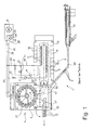
- FIG. 1 shows a schematic representation of a blow molding machine, which is connected to a furnace, which supplies the blow molding machine, the preforms with a defined temperature.
- FIG. 2 shows the schematic arrangement of a mold carrier, wherein a common actuating means is provided for the actuation of the first part of the mold carrier and the actuation of the second part of the mold carrier.
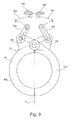
- FIG. 3 shows a further embodiment in which in each case a cam is assigned in the first part of the mold carrier and in the second part of the mold carrier.
- FIG. 4a shows the pivoting movement of the first part of the mold carrier and the second part of the mold carrier under the action of the actuating means.
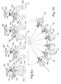
- FIG. 4b schematically shows the representation and the respective opening situation of the mold carrier as a function of the position of the mold carrier on the wheel on which the plurality of mold carriers is arranged.
- FIG. 5 also shows the different phases of the opening of the mold carrier, wherein the opening situation of the mold carrier is also shown graphically in dependence on the rotation angle omega of the wheel.
- FIG. 6a shows a first embodiment of the pivotal movement of the first part of the mold carrier and the second part of the mold carrier as a function of the angle of rotation of the wheel.
- FIG. 6b shows a second embodiment of the pivotal movement of the first part of the mold carrier and the second part of the mold carrier in dependence on the angle of rotation of the wheel.
- FIG. 6c shows a third embodiment of the pivoting movement of the first part of the mold carrier and the second part of the mold carrier as a function of the angle of rotation of the wheel.
- FIG. 6d shows a fourth embodiment of the pivoting movement of the first part of the mold carrier and the second part of the mold carrier in dependence on the position of the wheel.
- FIG. 1 shows a stretch blow molding machine 1, as known from the prior art.
- the stretch blow molding machine 1 will be described for the sake of completeness to the Insertion of preforms in a mold carrier 4 and the removal of a bottle from the mold carrier 4 to understand better.
- the stretch blow molding machine 1 has a blow molding machine 5 in the form of a blowing wheel equipped with a plurality of cooled mold carriers 4.
- the blowing wheel is continuously driven in the direction of the arrow.
- the blowing wheel is preceded by a heating station 3, which is designed in the form of a linear furnace and has a continuously circulating in the direction of arrow transport chain 14 for the preforms V. In the heating station, the preforms V with infrared radiant heaters 15 are brought to the temperature required for processing in the blowing station 5.
- the preforms V which have been heated to a processing temperature of, for example, 125 ° C., are transferred through a transfer wheel 17 which rotates continuously in the direction of the arrow.
- the feed of the preforms V to the transport chain is carried out by a continuously rotating in the arrow direction Einlaufsternrad 18. This receives the preforms 4 from a roller sorter 19 and a downwardly inclined chute 20.
- the stretch blow molding machine further comprises a cooling unit 6 with a heat exchanger 23 and a circulating pump 16 for the supply of cooling liquid, in the form of cooling water.
- a cooling unit 6 with a heat exchanger 23 and a circulating pump 16 for the supply of cooling liquid, in the form of cooling water.
- the blowing station 5 via a supply line 25 and a return line 26, and a rotary distributor 27 is connected directly.
- the cooling water circulates through the first part of the mold carrier and the second part of the mold carrier and cools the desired areas. This is indicated by some radial lines.
- the heating station 3 also has its own cooling liquid circuit with lines 29, 30, 31 and a circulating pump 7, in which a number of stationary heat sinks 2 is connected in series.
- the heatsink are z. B. at the height of the support ring of the preforms V and protect the threaded head against excessive heating, since this does not participate in the subsequent stretch blow molding.
- the heat sink 2 may be arranged on one side or on both sides of the movement path of the preforms V in the heating station 3. Further heat sinks can be provided for the radiant heaters 15 and their reflectors.
- the cooling water circuit of the heating station is in the range between backflow preventer 11 and circulating pump 7 through a further line 32 with the check valve to the coming of the cooling unit 6 supply line 35 and in the area between the backflow preventer 11 and the heat sink 2 through another line with a control valve 9 to the connected to the cooling unit 6 leading return line 26.
- the control valve 9 is controlled by a temperature controller 8 which is inserted in the cooling liquid circuit of the heating station 3, preferably in the region between the circulation pump 7 and the heat sink 2.
- FIG. 2 shows a schematic view of a mold carrier 50, in which a blow mold 4 is inserted.
- the mold carrier 50 consists of a first part 50a and a second part 50b.
- the blow mold consists of a first part 4a and a second part 4b.
- the first part of the mold carrier 50a and the second part of the mold carrier 50b are pivotable about a common axis 51. By pivoting about the axis 51, it is achieved that the first part of the mold carrier 50a and the second part of the mold carrier 50b are opened, so that a preform can be inserted into the mold carrier 50, or blow mold 4. Likewise, a finished bottle can be removed by opening the mold carrier 50 from the blow mold 4.
- actuating means 60 which moves the first part of the mold carrier and the second part of the mold carrier with respect to the plane of symmetry S non-uniform.
- the actuating means 60 is divided into two parts.
- the first part of the mold carrier 50a is connected to a tab 52a, to which a lever arm 56 engages, which is guided in a slot 57b of the lever arm 54b.
- the first part of the mold carrier 50a is connected to an operating lever 53a, which cooperates directly with the first actuating means 60a.
- the first actuating means 60a is shown as a cam.
- first actuating means 60a and the second actuating means 60b as cams is not to be construed as a limitation of the invention. It is obvious to a person skilled in the art that the corresponding levers, as in FIG. 2 shown, can also be operated with other actuating means. As a possible actuating means you can hydraulic Actuators or servomotors present, which act directly on the provided lever.
- the second part of the mold carrier 50b is also provided with a tab 52b, to which also a lever 56 is articulated, which is also guided in the guide 57b of the lever 54b.
- a lever system 58b To the lever 54b engages a lever system 58b, which cooperates with the second actuating means 60b.
- a corresponding deflection is thus exerted on the levers 53a, 58b and 54b, which ultimately leads to an individual movement of the first part of the mold carrier 50a and of the second part of the mold carrier 50b.
- any desired movement curve of the two parts of the mold carrier 50a and 50b can thus be achieved.
- FIG. 3 shows a further embodiment for the opening and closing of a mold carrier 50.
- the mold carrier 50 comprises a first part of the mold carrier 50a and a second part of the mold carrier 50b, both of which are pivotally mounted about a common axis 51.
- a tab 52a is attached in the first part of the mold carrier 50a.
- a tab 52b is attached to the second part of the mold carrier 50b.
- Levers 53a and 53b are articulated on both lugs 52a and 52b.
- the first part of the mold carrier 50a and the second part of the mold carrier 50b can be pivoted about the common axis 51 independently of one another via a lever system 58a or 58b assigned to the first part of the mold carrier 50a and the second part of the mold carrier 50b.
- the pivoting is, as already described in FIG. 2 a, carried out by means of a first and second actuating means 60 a, 60 b, respectively 60 b associated with the first part of the mold carrier 50 a and the second part of the mold carrier 50 b.
- any desired movement curve of the first part of the mold carrier 50a and of the second part of the mold carrier 50b can be realized.
- FIG. 4a shows various positions of the opening of the first part of the mold carrier 50a and the second part of the mold carrier 50b.
- a first presentation of the FIG. 4a the two parts of the mold carrier 50a and 50b are closed.
- the actuating means 60a and 60b are in mechanical contact with the lever 53a and the lever system 58b.
- the connection point to the first tab and the second tab of the first part of the mold carrier 50a and the second part of the mold carrier 50b are in the center of the guide 55b of the lever 54b and the lower part of the guide 57b.
- the first part of the mold carrier and the second part of the mold carrier 50a and 50b are evenly opened.
- FIG. 4b schematically shows the opening and closing of the mold carrier 50 in dependence on the position of the means of transport.
- the transport is shown as a wheel which rotates about a center 67.
- the wheel is shown in dashed lines in the illustration shown here.
- the axes 51 about which the mold carriers 50 can be pivoted lie substantially on the circumference of the wheel.
- FIG. 4b are shown in substantially six phases, which passes through the mold carrier 50 and is thereby opened, one of the two mold halves is opened further in the direction of rotation of the wheel or in the opposite direction of rotation of the wheel and the mold carrier 50 is finally closed again.
- the direction of rotation of the wheel takes place around the center 67 in the counterclockwise direction.
- the two parts of the mold carrier 50a and 50b are opened uniformly in the direction of rotation of the wheel.
- the first mold carrier is opened somewhat further against the direction of rotation of the wheel.
- the second part of the mold carrier 50b is then opened slightly further in the direction of rotation of the wheel.
- both parts of the mold carrier 50a and 50b are opened again evenly.
- both parts of the mold carrier 50a and 50b closed again.
- FIG. 5 b shows five phases for the opening of the mold carrier 50
- FIG. 5 also shown the position of the individual mold carrier as a function of the rotational position of the wheel.
- the interaction of the mold carrier 50 is shown with a transfer starwheel 17, which transfers the preheated preforms (V) to the second part of the mold carrier 50b.
- the individual phases are in FIG. 5 with a circle in which a number is marked.
- the two parts of the mold carrier 50a and 50b are closed. This is shown both in the linear representation, as well as in the representation of the individual mold carrier on the blowing wheel.
- a dashed cross is shown in the linear representation of the individual phases, wherein an axis 69 of the cross passes through the axis 51 of the mold carrier 50. With the aid of this axis 69 one can easily determine the individual dimensions of the pivotal movement of the first part of the mold carrier or the second part of the mold carrier 50a or 50b.
- the mold carrier 50 is open, that is, the first part of the mold carrier and the second part of the mold carrier 50a and 50b are each by a certain amount about the axis 51 a has been pivoted.
- the first part of the mold carrier 50a has been pivoted somewhat further counter to the direction of rotation 70 of the blowing wheel.
- the open mold carrier acts in phase 2 with the outlet star wheel 21 together.
- corresponding removal means (not shown) are provided which remove the bottle from the first part of the mold carrier 50a.
- the blowing wheel continues to rotate and reaches phase 3 after another angle Omega.
- the first part of the mold carrier and the second part of the mold carrier 50a and 50b are opened at the same angle with respect to the axis 69.
- the first part of the mold carrier 50a begins to close again and the second part of the mold carrier 50b possibly swings a bit further.
- the transfer wheel 17 thus supplies a preform to the second part of the mold carrier 50b. After the preform has been transferred by the transfer wheel 17 to the second part of the mold carrier 50b, it is closed.
- the mold carrier is then completely closed when the blowing wheel has reached phase 5.
- FIGS. 6a to 6d show various ways in which the individual pivoting movements of the first part of the mold carrier and the second part of the mold carrier can be composed, while a mold carrier passes through the phases 1 to 5 during the rotation of a blowing wheel by the angle omega.
- the angle of rotation omega of the blowing wheel is plotted in all figures on the abscissa 71.
- the opening angle of the first part of the mold carrier and the second part of the mold carrier 50a and 50b is plotted.
- the function 73 of the opening angle ⁇ of the first part of the mold carrier 50a and the function 74 of the opening angle ⁇ of the second part of the mold carrier 50b is a continuously differentiable function.
- FIG. 6b It can be seen that the first part of the mold carrier 50a opens faster and the second part of the mold carrier 50b opens later depending on the angle of rotation of the blowing wheel.
- the maximum opening angles are at all FIGS. 6a to 6d reached at different times. In the embodiment shown here, the maximum opening angle of the first part of the mold carrier 50 a is already reached by the phase 2.
- the maximum opening angle of the second part of the mold carrier 50b is achieved approximately at phase 4.
- FIG. 6c shows a further embodiment of the opening and closing of the first part of the mold carrier and the second part of the mold carrier 50a and 50b.
- the second part of the mold carrier 50b moves slightly counter to the direction of rotation of the blowing wheel.
- the first part of the mold carrier 50a moves slightly counter to the direction of rotation of the blowing wheel.
- FIG. 6b shows another embodiment of opening and closing the mold carrier 50.
- the second part of the mold carrier 50b moves slightly in the direction of the direction of rotation of the blowing wheel.
- beta of the second part of the blowing wheel 50b which remains substantially constant between the first and the second phase.
- a small opening angle alpha of the first part of the mold carrier 50a arises between the fourth and fifth phase.
- control of the actuating means of the first part of the mold carrier and of the second part of the mold carrier 50a and 50b can be selected in a corresponding manner in order to realize desired movement curves of the individual parts of the mold carrier 50a and 50b by the user a simple and damage-free removal of the finished blown bottles from the mold carrier and the insertion of a preform is facilitated in the mold carrier.
Landscapes
- Engineering & Computer Science (AREA)
- Manufacturing & Machinery (AREA)
- Mechanical Engineering (AREA)
- Blow-Moulding Or Thermoforming Of Plastics Or The Like (AREA)
Abstract
Description
- Die vorliegende Erfindung betrifft ein Verfahren zum Einsetzen eines Vorformlings in und zur Entnahme einer Flasche aus einer Blasmaschine. Dabei besitzt die Blasmaschine eine Vielzahl an einem Transportmittel angeordnete, zweiteilige Formenträger. Die Formenträger können zur Entnahme der Flasche geöffnet und nach dem Einsetzen des Vorformlings wieder geschlossen werden.
- Ferner betrifft die Erfindung eine Vorrichtung zum Einsetzen eines Vorformlings in und zur Entnahme einer Flasche aus einer Blasmaschine. Die Blasmaschine besitzt eine Vielzahl an einem Transportmittel angeordnete, zweiteilige Formenträger. Ein erster Teil des Formenträgers und ein zweiter Teil des Formenträgers sind um eine gemeinsame Achse schwenkbar miteinander verbunden.
- Eine Blasmaschine wird insbesondere zum Streckblasen von Vorformlingen verwendet. Die Blasmaschine selbst umfasst dabei mindestens eine Blasform. Für das Streckblasen von Vorformlingen für Kunststoffflaschen werden Blasformen verwendet, in die ein Vorformling mit Überdruck im Innern der Blasform formgeblasen, d. h., auskonturiert wird. Die Blasform kann dabei z. B. zwei Formhälften umfassen, die um eine gemeinsame Achse drehbar gelagert sind. Durch Drehen um diese Achse können die Formhälften geöffnet und verschlossen werden, In die geöffneten Formhälften kann ein Vorformling eingesetzt bzw eine formgeblasene Flasche entnommen werden. Die Ausgestaltung eines solchen Formträgers ist z. B. in der Europäischen Patentschrift
EP 1 276 598 B1 offenbart. - Das
U.S.-Patent 4,313,720 offenbart ein System für die kontinuierliche Herstellung von Plastikflaschen, bei der vorgewärmte Vorformlinge in eine Blasform eingeblasen werden, um somit der gewünschten Flasche die entsprechende Form zu verleihen. Es ist eine Vielzahl von Speicherstationen für die Vorformlinge vorgesehen. Die Vorformlinge werden an eine drehbare Blasstation übergeben, die eine Vielzahl von Formenträgern trägt. Jede der Blasstationen besteht aus einem ersten Teil eines Formenträgers und einem zweiten Teil eines Formenträgers. An der Entnahmestation der Flasche kann der in Drehrichtung des Formenträgerrades angeordnete Teil des Formenträgers weggeschwenkt werden, um die Entnahme der fertigen Flasche zu erleichtern. Für das Einsetzen des Vorformlings in die leere Form wird der der Drehrichtung des Formenträgerrades nachlaufende Teil des Formenträgers weggeschwenkt und der Vorformling wird in den Teil des Formenträgers eingesetzt, der sich bereits wieder in der Position befindet, die dann für den geschlossenen Formenträger maßgeblich ist. Dem Stand der Technik kann nicht entnommen werden, wie die einzelnen Hälften des jeweiligen Formenträgers an der Entnahmestation, bzw. an der Einsetzstation bewegt werden, um ein schnelles und kollisionsfreies Einsetzen und Entnehmen zu gewährleisten. - Aufgabe der Erfindung ist, ein Verfahren zu schaffen, mit dem das Einsetzen eines Vorformlings in einen Formenträger der Blasmaschine und das Entnehmen einer fertigen Flasche aus der Blasmaschine erleichtert wird. Dabei sollen auch evtl. Beschädigung des Vorformlings, bzw. der fertigen Flasche an dem ersten Teil des Formenträgers, bzw. am zweiten Teil des Formenträgers vermieden werden.
- Die obige Aufgabe wird gelöst durch ein Verfahren, dass die Merkmale des Anspruchs 1 umfasst.
- Ferner ist es Aufgabe der gegenwärtigen Erfindung eine Vorrichtung zu schaffen, mit der es möglich ist, auf einfache Weise aus dem Formenträger einer Blasmaschine zu Entnehmen und ein Vorformling in den entsprechenden Formenträger einer Blasmaschine einzusetzen. Dabei sollen evtl. Beschädigungen bei der Entnahme, bzw. dem Einsetzen vermieden werden.
- Die obige Aufgabe wird durch eine Vorrichtung gelöst, die die Merkmale des Anspruchs 7 umfasst.
- Das Verfahren zum Einsetzen eines Vorformlings in und zur Entnahme einer Flasche aus einer Blasmaschine ist von besonderem Vorteil, da mit einem Transportmittel die Formenträger gleichmäßig mit einer definierten Geschwindigkeit zu einer Stelle der Blasmaschine gedreht werden, an der das Entnehmen der Flasche und das Einsetzen des Vorformlings durchgeführt wird. Der Formenträger ist dabei aus einem ersten Teil und einem zweiten Teil aufgebaut, und definiert eine Symmetrieebene. Der erste Teil des Formenträgers und der zweite Teil des Formenträgers werden bezüglich der Symmetrieebene (S) ungleichmäßig bewegt.
- Der erste Teil des Formenträgers und der zweite Teil des Formenträgers werden durch jeweils ein Betätigungsmittel angesteuert. Eine weitere Möglichkeit ist, dass der erste Teil des Formenträgers und der zweite Teil des Formenträgers durch ein gemeinsames Betätigungsmittel angesteuert werden. In diesem Fall ist das gemeinsame Betätigungsmittel zweigeteilt, wobei ein erster Teil die Öffnungs- und Schließbewegung des ersten Teils des Formenträgers und des zweiten Teils des Formenträgers steuert und ein zweiter Teil die ungleichmäßige Bewegung bezüglich der Symmetrieebene steuert.
- Das Entnehmen der Flasche und das Einsetzen des Vorformlings wird in mehrere Phasen unterteilt. Dabei erreicht die Schwenkbewegung des ersten Teil des Vorformlings in Transportrichtung des Transportmittels in einer Phase die größte Geschwindigkeit, die vor derjenigen Phase liegt, in der der zweite Teil des Formenträgers in Transportrichtung des Transportmittels ebenfalls die größte Geschwindigkeit erreicht.
- In einer besonders bevorzugten Ausführungsform ist das Transportmittel als Rad ausgebildet, an dessen Umfang die Vielzahl der Formenträger angeordnet sind.
- Ein durch die Schwenkbewegung des ersten Teils des Formenträgers bedingter erster Öffnungswinkel stellt in Abhängigkeit vom Drehwinkel des Rades eine stetig differenzierbare Funktion dar. Ebenso stellt die Schwenkbewegung des zweiten Teils des Formenträgers in Bezug auf einen zweiten Öffnungswinkel ebenfalls eine stetig differenzierbare Funktion des Drehwinkels des Rades dar. Die Maxima der beiden Funktionen sind gegeneinander in Abhängigkeit vom Drehwinkel des Rades versetzt.
- Der erste Teil und der zweite Teil des gemeinsamen Betätigungsmittels ist eine Kurvenscheibe, durch die der erste Teil des Formenträgers und der zweite Teil des Formenträgers in eine Schwenkbewegung versetzt werden. Ebenso ist es denkbar, dass das Betätigungsmittel als ein hydraulisches Mittel ausgebildet ist. Dabei kann sowohl dem ersten Teil des Formenträgers, als auch dem zweiten Teil des Formenträgers jeweils ein hydraulisches Mittel zugeordnet sein. Ebenso kann man das Betätigungsmittel als einen Elektromotor ausbilden. Mit der individuellen Zuordnung der Betätigungsmittel zum ersten Teil des Formenträgers und zum zweiten Teil des Formenträgers kann man je nach Ausgestaltung des Betätigungsmittels eine beliebige Bewegungskurve des ersten Teils des Formenträgers, bzw. des zweiten Teils des Formenträgers fahren, um dadurch optimale Bedingungen für das Einsetzen eines Vorformlings in einem Teil des Formenträgers und das Entnehmen einer fertigen Flasche aus dem geöffneten Formenträger zu erzielen. Für die Entnahme der fertigen Flasche aus dem Formenträger und das Einsetzen des Vorformlings in den Formenträger ist es nicht unbedingt erforderlich, dass das erste Teil des Formenträgers und der zweite Teil des Formenträgers die maximal mögliche Schwenkbewegung durchgeführt haben. Durch die Erfindung ist es möglich, den ersten Teil des Formenträgers, bzw. den zweiten Teil des Formenträgers soweit zu schwenken, dass damit eine optimale Entnahme unter Berücksichtigung der Bewegung des Transportmittels möglich ist.
- Der Vorteil der erfindungsgemäßen Vorrichtung ist, dass dem ersten Teil des Formenträgers und dem zweiten Teil des Formenträgers jeweils ein Betätigungsmittel zugeordnet ist. Jedes Betätigungsmittel kann somit unabhängig voneinander den ersten Teil des Formenträgers und den zweiten Teil des Formenträgers um die gemeinsame Achse schwenken. Ebenso ist es denkbar, dass sowohl der erste Teil des Formenträgers als auch der zweite Teil des Formenträgers jeweils eine Schwenkachse besitzt.
- Die mit den einzelnen Betätigungsmitteln dem ersten Teil des Formenträgers und dem zweiten Teil des Formenträgers aufgeprägten Bewegungskurven, bzw. Schwenkbewegungen stellen jeweils in Abhängigkeit vom Drehwinkel des Rades, an dem die Formenträger angeordnet sind, eine stetig differenzierbare Funktion dar. Dies bedeutet, dass über den gesamten Verlauf der Schwenkbewegung kein abruptes Abstoppen der Schwenkbewegung des ersten Teils des Formenträgers, bzw. des zweiten Teils des Formenträgers stattfindet.
- Im Folgenden sollen Ausführungsbeispiele die Erfindung und ihre Vorteile anhand der beigefügten Figuren näher erläutern.
-
Figur 1 zeigt eine schematische Darstellung einer Blasmaschine, die mit einem Ofen verbunden ist, der der Blasmaschine die Vorformlinge mit einer definierten Temperatur zuführt. -
Figur 2 zeigt die schematische Anordnung eines Formenträgers, wobei für die Betätigung des ersten Teils des Formenträgers und die Betätigung des zweiten Teils des Formenträgers ein gemeinsames Betätigungsmittel vorgesehen ist. -
Figur 3 zeigt eine weitere Ausführungsform, bei der im ersten Teil des Formenträgers und im zweiten Teil des Formenträgers jeweils eine Kurvenscheibe zugeordnet ist. -
Figur 4a zeigt die Schwenkbewegung des ersten Teils des Formenträgers und des zweiten Teils des Formenträgers unter Einwirkung des Betätigungsmittels. -
Figur 4b zeigt schematisch die Darstellung und die jeweilige Öffnungssituation des Formenträgers in Abhängigkeit der Position des Formenträgers am Rad, an welchem die Vielzahl der Formenträger angeordnet ist. -
Figur 5 zeigt ebenfalls die unterschiedlichen Phasen der Öffnung des Formenträgers, wobei die Öffnungssituation des Formenträgers ebenfalls graphisch in Abhängigkeit vom Drehwinkel Omega des Rades dargestellt ist. -
Figur 6a zeigt eine erste Ausführungsform der Schwenkbewegung des ersten Teils des Formenträgers und des zweiten Teils des Formenträgers in Abhängigkeit vom Drehwinkel des Rades. -
Figur 6b zeigt eine zweite Ausführungsform der Schwenkbewegung des ersten Teils des Formenträgers und des zweiten Teils des Formenträgers in Abhängigkeit vom Drehwinkel des Rades. -
Figur 6c zeigt eine dritte Ausführungsform der Schwenkbewegung des ersten Teils des Formenträgers und des zweiten Teils des Formenträgers in Abhängigkeit vom Drehwinkel des Rades. -
Figur 6d zeigt eine vierte Ausführungsform der Schwenkbewegung des ersten Teils des Formenträgers und des zweiten Teils des Formenträgers in Abhängigkeit von der Position des Rades. -
Figur 1 zeigt eine Streckblasmaschine 1, wie sie aus dem Stand der Technik bekannt ist. Die Streckblasmaschine 1 soll der Vollständigkeit halber beschrieben werden, um das Einsetzen von Vorformlingen in einen Formenträger 4 und das Entnehmen einer Flasche aus dem Formenträger 4 besser verstehen zu können. Die Streckblasmaschine 1 besitzt eine Blasmaschine 5 in Form eines mit mehreren gekühlten Formenträgern 4 bestückten Blasrades. Das Blasrad wird in Pfeilrichtung kontinuierlich angetrieben. Dem Blasrad ist eine Heizstation 3 vorgeschaltet, die in Form eines Linearofens ausgestaltet ist und eine in Pfeilrichtung kontinuierlich umlaufende Transportkette 14 für die Vorformlinge V aufweist. In der Heizstation werden die Vorformlinge V mit Infrarot-Heizstrahlern 15 auf die für die Verarbeitung in der Blasstation 5 erforderliche Temperatur gebracht. - Zwischen der Transportkette 14 und den geöffneten Blasformen 4 werden die auf eine Verarbeitungstemperatur von beispielsweise 125 °C erwärmten Vorformlinge V durch ein in Pfeilrichtung kontinuierlich rotierendes Transferrad 17 überführt. Die Zufuhr der Vorformlinge V zur Transportkette erfolgt durch ein in Pfeilrichtung kontinuierlich umlaufendes Einlaufsternrad 18. Dieses erhält die Vorformlinge 4 von einem Walzensortierer 19 und einer nach unten geneigten Rutsche 20. Die in den geschlossenen Glasformen nach mechanischer Vorstreckung durch nicht gezeigte Reckstangen und durch Zufuhr von Druckluft fertig geblasenen und an den gekühlten Wänden der Formenträger 4 befestigten flaschenförmigen Hohlkörper H werden durch ein in Pfeilrichtung kontinuierlich umlaufendes Auslaufsternrad 21 aus den geöffneten Formenträgern 4 entnommen und an einen Abförderer 22 übergeben. Die Streckblasmaschine umfasst weiter ein Kühlaggregat 6 mit einem Wärmetauscher 23 und einer Umwälzpumpe 16 zur Lieferung von Kühlflüssigkeit, in Form von Kühlwasser. An den Wärmetauscher 23 ist die Blasstation 5 über eine Zulaufleitung 25 und eine Rücklaufleitung 26, sowie einen Drehverteiler 27 direkt angeschlossen. Das Kühlwasser zirkuliert durch den ersten Teil des Formenträgers und den zweiten Teil des Formenträgers und kühlt die gewünschten Bereiche. Dies ist durch einige radiale Leitungen angedeutet. Die Heizstation 3 weist ebenfalls einen eigenen Kühlflüssigkeitskreislauf mit Leitungen 29, 30, 31 und einer Umwälzpumpe 7 auf, in dem eine Reihe von stationären Kühlkörpern 2 hintereinander geschaltet ist. Die Kühlkörper sind z. B. auf Höhe des Tragrings der Vorformlinge V angeordnet und schützen den Gewindekopf gegen übermäßige Erwärmung, da dieser an der nachfolgenden Streck-Blasverformung nicht teilnimmt. Die Kühlkörper 2 können an einer Seite oder an beiden Seiten der Bewegungsbahn der Vorformlinge V in der Heizstation 3 angeordnet sein. Weitere Kühlkörper können für die Heizstrahler 15 und deren Reflektoren vorgesehen sein.
- Der Kühlwasserkreislauf der Heizstation ist im Bereich zwischen Rückflußverhinderer 11 und Umwälzpumpe 7 durch eine weitere Leitung 32 mit dem Rückschlagventil an die vom Kühlaggregat 6 kommende Zulaufleitung 35 und im Bereich zwischen dem Rückflußverhinderer 11 und dem Kühlkörper 2 durch eine weitere Leitung mit einem Regelventil 9 an die zum Kühlaggregat 6 führende Rücklaufleitung 26 angeschlossen. Das Regelventil 9 wird durch einen Temperaturregler 8 gesteuert, der in den Kühlflüssigkeitskreislauf der Heizstation 3 eingefügt ist, vorzugsweise im Bereich zwischen der Umwälzpumpe 7 und dem Kühlkörper 2.
- In der nachfolgenden Beschreibung sei darauf hingewiesen, dass in den verschiedenen Figuren für gleiche Elemente die gleichen Bezugszeichen verwendet werden.
-
Figur 2 zeigt eine schematische Ansicht eines Formenträgers 50, in dem eine Blasform 4 eingesetzt ist. Der Formenträger 50 besteht aus einem ersten Teil 50a und einem zweiten Teil 50b. Ebenso besteht die Blasform aus einem ersten Teil 4a und einem zweiten Teil 4b. Der erste Teil des Formenträgers 50a und der zweite Teil des Formenträgers 50b sind um eine gemeinsame Achse 51 schwenkbar. Durch das Schwenken um die Achse 51 wird erreicht, dass der erste Teil des Formenträgers 50a und der zweite Teil des Formenträgers 50b geöffnet werden, damit ein Vorformling in den Formenträger 50, bzw. Blasform 4 eingesetzt werden kann. Ebenso kann eine fertige Flasche durch das Öffnen des Formenträgers 50 aus der Blasform 4 entnommen werden. - Es ist ein gemeinsames Betätigungsmittel 60 vorgesehen, das den ersten Teil des Formenträgers und den zweiten Teil des Formenträgers bezüglich der Symmetrieebene S ungleichmäßig bewegt. In der hier gezeigten Ausführungsform ist das Betätigungsmittel 60 zweigeteilt. Der erste Teil des Formenträgers 50a ist mit einer Lasche 52a verbunden, an die ein Hebelarm 56 angreift, der in einem Schlitz 57b des Hebelarms 54b geführt ist. Ebenso ist der erste Teil des Formenträgers 50a mit einem Betätigungshebel 53a verbunden, der direkt mit dem ersten Betätigungsmittel 60a zusammen wirkt. In der hier dargestellten Ausführungsform ist das erste Betätigungsmittel 60a als eine Kurvenscheibe dargestellt. Die Ausführung des ersten Betätigungsmittels 60a und des zweiten Betätigungsmittels 60b als Kurvenscheiben soll nicht als eine Beschränkung der Erfindung aufgefasst werden. Es ist für einen Fachmann selbstverständlich, dass die entsprechenden Hebel, wie in
Figur 2 dargestellt, auch mit anderen Betätigungsmitteln betätigt werden können. Als mögliche Betätigungsmittel kann man sich hydraulische Betätigungsmittel oder Servomotoren vorstellen, die direkt an die vorgesehenen Hebel angreifen. - Der zweite Teil des Formenträgers 50b ist ebenfalls mit einer Lasche 52b versehen, an die ebenfalls ein Hebel 56 angelenkt ist, der ebenfalls in der Führung 57b des Hebels 54b geführt ist. An den Hebel 54b greift ein Hebelsystem 58b an, das mit dem zweiten Betätigungsmittel 60b zusammenwirkt. Durch die Bewegung des ersten und des zweiten Betätigungsmittels 60a und 60b wird somit eine entsprechende Auslenkung auf die Hebel 53a, bzw. 58b und 54b ausgeübt, was letztendlich zu einer individuellen Bewegung des ersten Teils des Formenträgers 50a und des zweiten Teils des Formenträgers 50b führt. Durch die individuelle Anlenkung, bzw. individuelle Betätigung des ersten Teils des Formenträgers 50a und des zweiten Teils des Formenträgers 50b kann somit eine beliebige Bewegungskurve der beiden Teile des Formenträgers 50a und 50b erreicht werden.
-
Figur 3 zeigt eine weitere Ausführungsform für das Öffnen und Schließen eines Formenträgers 50. Wie bereits in dem Ausführungsbeispiel zuFigur 2 beschrieben, umfasst der Formenträger 50 einen ersten Teil des Formenträgers 50a und einen zweiten Teil des Formenträgers 50b, die beide um eine gemeinsame Achse 51 schwenkbar angebracht sind. Im ersten Teil des Formenträgers 50a ist eine Lasche 52a angebracht. Ebenso ist am zweiten Teil des Formenträgers 50b eine Lasche 52b angebracht. An beiden Laschen 52a und 52b sind jeweils Hebelelemente 53a, bzw. 53b angelenkt. Über ein dem ersten Teil des Formenträgers 50a und dem zweiten Teil des Formenträgers 50b zugeordnetes Hebelsystem 58a, bzw. 58b können der erste Teil des Formenträgers 50a und der zweite Teil des Formenträgers 50b unabhängig voneinander um die gemeinsame Achse 51 geschwenkt werden. Die Schwenkung wird wie bereits in Figur 2a beschrieben, mittels eines entsprechend dem ersten Teil des Formenträgers 50a und dem zweiten Teil des Formenträgers 50b zugeordneten ersten und zweiten Betätigungsmittels 60a, bzw. 60b durchgeführt. Je nach Ausgestaltung der am ersten bzw. zweiten Betätigungsmittel 60a und 60b angebrachten Kurven kann eine beliebige Bewegungskurve des ersten Teils des Formenträgers 50a und des zweiten Teils des Formenträgers 50b realisiert werden. -
Figur 4a zeigt verschiedene Stellungen der Öffnung des ersten Teils des Formenträgers 50a und des zweiten Teils des Formenträgers 50b. Einer ersten Darstellung derFigur 4a sind die beiden Teile des Formenträgers 50a und 50b geschlossen. Die Betätigungsmittel 60a und 60b sind in mechanischem Kontakt mit dem Hebel 53 a und dem Hebelsystem 58b. Die Verbindungsstelle zu der ersten Lasche und der zweiten Lasche des ersten Teils des Formenträgers 50a und des zweiten Teils des Formenträgers 50b sind dabei in der Mitte der Führung 55b des Hebels 54b und am unteren Teil der Führung 57b. Bei der nächsten inFigur 4a gezeigten Stellung sind der erste Teil des Formenträgers und der zweite Teil des Formenträgers 50a und 50b gleichmäßig geöffnet. Hierzu befindet sich die Verbindungsstelle zu der ersten Lasche und der zweiten Lasche am oberen Teil der Führung 57b und etwa in der Mitte der Führung 55b des Hebels 54b. In der nächsten Darstellung derFigur 4a liegt die Verbindungsstelle zu den beiden Laschen des ersten Teils des Formenträgers und des zweiten Teils des Formenträgers 50a und 50b am rechten Rand der Führung 55b des Hebels 54b an. Dadurch erreicht man eine weitere Schwenkbewegung des ersten Teils des Formenträgers 50a in Richtung des Pfeils 65. In der letzten Darstellung derFigur 4a liegt die Verbindungsstelle zu den beiden Laschen des ersten Teils des Formenträgers und des zweiten Teils des Formenträgers 50a und 50b links an der Führung 55b des Hebels 54b an. Dadurch wird erreicht, dass der zweite Teil des Formenträgers 50b weiter in Richtung des Pfeils 66 schwenkt. -
Figur 4b zeigt schematisch das Öffnen und das Schließen des Formenträgers 50 in Abhängigkeit von der Stellung des Transportmittels. In der hier dargestellten Ausführungsform ist das Transportmittel als Rad dargestellt, welches sich um einen Mittelpunkt 67 dreht. In Abhängigkeit von der Drehstellung des Rades werden die Formenträger in entsprechender Weise geöffnet. Das Rad ist in der hier gezeigten Darstellung gestrichelt eingezeichnet. Die Achsen 51, um welche die Formenträger 50 geschwenkt werden können, liegen im Wesentlichen auf dem Umfang des Rades. InFigur 4b sind im Wesentlichen sechs Phasen dargestellt, die der Formenträger 50 durchläuft und dabei geöffnet wird, eine der beiden Formenhälften weiter geöffnet wird in Drehrichtung des Rades oder in entgegen gesetzter Drehrichtung des Rades und wobei der Formenträger 50 letztendlich wieder geschlossen wird. Die Drehrichtung des Rades erfolgt dabei um den Mittelpunkt 67 im Gegenuhrzeigersinn. Zunächst werden die beiden Teile des Formenträgers 50a und 50b in Drehrichtung des Rades gleichmäßig geöffnet. Wenn sich das Rad weiterdreht, wird der erste Formenträger etwas weiter entgegen der Drehrichtung des Rades geöffnet. Bei einer Weiterdrehung des Rades wird dann der zweite Teil des Formenträgers 50b etwas weiter in Drehrichtung des Rades geöffnet. Kurz vor dem Schließen der beiden Teile des Formenträgers 50a und 50b sind beide Teile des Formenträgers 50a und 50b wieder gleichmäßig geöffnet. Letztendlich werden bei einer Weiterdrehung des Rades beide Teile des Formenträgers 50a und 50b wieder geschlossen. - Figur 5b stellt fünf Phasen dar für das Öffnen des Formenträgers 50. Zusätzlich ist in der
Figur 5 ebenfalls die Stellung der einzelnen Formenträger in Abhängigkeit von der Drehstellung des Rades dargestellt. Dabei ist ebenfalls das Zusammenwirken des geöffneten Formenträgers 50 mit einem Auslaufsternrad 21, welches die fertigen Flüssigkeitsbehälter übernimmt. Ebenso ist das Zusammenwirken des Formenträgers 50 mit einem Transfersternrad 17 dargestellt, das die vorgewärmten Vorformlinge (V) an den zweiten Teil des Formenträgers 50b übergibt. Die einzelnen Phasen sind inFigur 5 mit einem Kreis, in dem eine Zahl eingezeichnet ist, gekennzeichnet. In der ersten Phase sind die beiden Teile des Formenträgers 50a und 50b geschlossen. Dies ist sowohl in der linearen Darstellung, als auch in der Darstellung der einzelnen Formenträger auf dem Blasrad so eingezeichnet. Ebenso ist in der linearen Darstellung der einzelnen Phasen ein gestricheltes Kreuz eingezeichnet, wobei eine Achse 69 des Kreuzes durch die Achse 51 des Formenträgers 50 verläuft. Mit Hilfe dieser Achse 69 kann man einfach die einzelnen Ausmaße der Schwenkbewegung des ersten Teils des Formenträgers oder des zweiten Teils des Formenträgers 50a oder 50b ermitteln. - Indem sich das Blasrad um den Mittelpunkt 67 um einen Winkel Omega in Richtung des Pfeils 70 gedreht hat, ist der Formenträger 50 geöffnet, d. h. der erste Teil des Formenträgers und der zweite Teil des Formenträgers 50a und 50b sind jeweils um einen gewissen Betrag um die Achse 51 a geschwenkt worden. Wie aus der Darstellung der Phase 2 in
Figur 5 ersichtlich ist, wurde der erste Teil des Formenträgers 50a etwas weiter entgegen der Drehrichtung 70 des Blasrades geschwenkt. Wie auch inFigur 5 dargestellt, erfolgt bei der Phase 2 das Entnehmen der fertig geblasenen Flaschen aus dem geöffneten Formenträger. Dabei wirkt der geöffnete Formenträger in Phase 2 mit dem Auslaufsternrad 21 zusammen. Am Auslaufsternrad 21 sind entsprechende Entnahmemittel (nicht dargestellt) vorgesehen, die die Flasche vom ersten Teil des Formenträgers 50a entnehmen. Das Blasrad dreht sich kontinuierlich weiter und erreicht nach einem weiteren Winkel Omega die Phase 3. Hier sind der erste Teil des Formenträgers und der zweite Teil des Formenträgers 50a und 50b um den gleichen Winkel bzgl. der Achse 69 geöffnet. Bei der vierten Phase beginnt sich bereits der erste Teil des Formenträgers 50a wieder zu schließen und der zweite Teil des Formenträger 50b schwenkt sich ggf. noch etwas weiter auf. Bei der dritten Phase wirkt der Formenträger 50 mit dem Transferrad 17 für die Vorformlinge zusammen. Das Transferrad 17 führt somit einen Vorformling dem zweiten Teil des Formenträgers 50b zu. Nachdem der Vorformling durch das Transferrad 17 an den zweiten Teil des Formenträgers 50b übergeben wurde, wird dieser geschlossen. Der Formenträger ist dann komplett geschlossen, wenn das Blasrad die Phase 5 erreicht hat. - Die
Figuren 6a bis 6d zeigen verschiedene Möglichkeiten, wie die einzelnen Schwenkbewegungen des ersten Teils des Formenträgers und des zweiten Teils des Formenträgers zusammengesetzt sein können, während ein Formenträger die Phasen 1 bis 5 bei der Drehung eines Blasrades um den Winkel Omega durchläuft. Dabei ist in allen Figuren auf der Abszisse 71 der Drehwinkel Omega des Blasrades aufgetragen. Auf der Ordinate 72 ist der Öffnungswinkel des ersten Teils des Formenträgers und des zweiten Teils des Formenträgers 50a und 50b aufgetragen. Wie aus allenFiguren 6a bis 6d ersichtlich ist, ist die Funktion 73 des Öffnungswinkels α des ersten Teils des Formenträgers 50a und die Funktion 74 des Öffnungswinkels β des zweiten Teils des Formenträgers 50b eine stetig differenzierbare Funktion. InFigur 6b ist ersichtlich, dass sich der erste Teil des Formenträgers 50a schneller öffnet und der zweite Teil des Formenträgers 50b sich erst später in Abhängigkeit vom Drehwinkel des Blasrades öffnet. Die maximalen Öffnungswinkel sind bei allenFiguren 6a bis 6d zu unterschiedlichen Zeitpunkten erreicht. In der hier dargestellten Ausführungsform wird der maximale Öffnungswinkel des ersten Teils des Formenträgers 50a bereits um die Phase 2 erreicht. Der maximale Öffnungswinkel des zweiten Teils des Formenträgers 50b wird etwa bei Phase 4 erreicht.Figur 6c zeigt eine weitere Ausführungsform des Öffnens und des Schließens des ersten Teils des Formenträgers und des zweiten Teils des Formenträgers 50a und 50b. Zwischen der ersten und der zweiten Phase der Drehbewegung des Blasrades bewegt sich der zweite Teil des Formenträgers 50b etwas entgegen der Drehrichtung des Blasrades. Ebenso bewegt sich zwischen der vierten Phase und der fünften Phase der erste Teil des Formenträgers 50a etwas entgegen der Drehrichtung des Blasrades. Eine weitere Ausführungsform des Öffnens und des Schließens des Formenträgers 50 ist inFigur 6b dargestellt. Hier bewegt sich zunächst zwischen der ersten und der zweiten Phase der zweite Teil des Formenträgers 50b etwas in Richtung der Drehrichtung des Blasrades. Es stellt sich somit ein kleiner Öffnungswinkel Beta des zweiten Teils des Blasrades 50b ein, welcher zwischen der ersten und der zweiten Phase im Wesentlichen konstant bleibt. Ebenso stellt sich zwischen der vierten und fünften Phase ein kleiner Öffnungswinkel Alpha des ersten Teils des Formenträgers 50a ein. - Ebenso bleibt zwischen der vierten und fünften Phase dieser kleine Öffnungswinkel konstant. Erst in der Phase 4 sind dann beide Teile des Formenträgers 50a und 50b wieder geschlossen. Die in
Figur 6a bis 6d dargestellten Bewegungskurven der Teile des Formenträgers 50a und 50b stellen lediglich eine Auswahl von vielen Möglichkeiten dar. - Dies sollen ebenfalls nicht als eine Beschränkung der Erfindung aufgefasst werden. Es ist für einen Fachmann selbstverständlich, dass man die Steuerung der Betätigungsmittel des ersten Teils des Formenträgers und des zweiten Teils des Formenträgers 50a und 50b in entsprechender Weise wählen kann, um vom Benutzer gewünschte Bewegungskurven der einzelnen Teile des Formenträgers 50a und 50b zu realisieren, damit ein möglichst einfaches und beschädigungsfreies Entnehmen der fertig geblasenen Flaschen aus den Formenträger und das Einsetzen eines Vorformlings in den Formenträger erleichtert ist. - Die Erfindung wurde unter Bezugnahme auf eine bevorzugte Ausführungsform beschrieben. Es ist jedoch für einen Fachmann vorstellbar, dass Abwandlungen oder Änderungen der Erfindung gemacht werden können, ohne dabei den Schutzbereich der nachstehenden Ansprüche zu verlassen.
Claims (16)
- Verfahren zum Einsetzen eines Vorformlings (V) in und zur Entnahme einer Flasche (H) aus einer Blasmaschine (5), wobei die Blasmaschine (5) eine Vielzahl, an einem Transportmittel angeordnete, mindestens zweiteilige Formenträger (50) umfasst, der eine Symmetrieebene (S) definiert, wobei die Formenträger (50) zur Entnahme der Flasche (H) geöffnet und nach dem Einsetzen des Vorformlings (V) ebenso geschlossen werden, gekennzeichnet durch die folgenden Schritte:■ dass mit dem Transportmittel die Formenträger (50) gleichmäßig mit einer definierten Geschwindigkeit zur einer Stelle der Blasmaschine (5) gedreht werden, an der das Entnehmen der Flasche (H) und das Einsetzen des Vorformlings (V) durchgeführt wird; und■ dass ein erster Teil des Formenträgers (50a) und ein zweiter Teil des Formenträgers (50b) bezüglich der Symmetrieebene (S) ungleichmäßig bewegt werden.
- Verfahren nach Anspruch 1, dadurch gekennzeichnet, dass der erste Teil des Formenträgers (50a) und der zweite Teil des Formenträgers (50b) durch jeweils ein Betätigungsmittel (60a, 60b) angesteuert werden.
- Verfahren nach Anspruch 1, dadurch gekennzeichnet, dass der erste Teil des Formenträgers (50a) und der zweite Teil des Formenträgers (50b) durch ein gemeinsames Betätigungsmittel (60) angesteuert werden.
- Verfahren nach Anspruch 3, dadurch gekennzeichnet, dass das gemeinsames Betätigungsmittel (60) zweigeteilt ist, wobei ein erster Teil (60b) die Öffnungs- und Schließbewegung des ersten Teils des Formenträgers (50a) und des zweiten Teils des Formenträgers (50b) steuert und ein zweiter Teil (60a) die ungleichmäßige Bewegung bezüglich der Symmetrieebene (S) steuert.
- Verfahren nach einem der Ansprüche 1 bis 4, dadurch gekennzeichnet, dass das Entnehmen der Flasche (H) und das Einsetzen des Vorformlings (V) in mehrere Phasen unterteilt wird, wobei die größte Geschwindigkeit der Schwenkbewegung des ersten Teils des Formenträgers (50a) in Transportrichtung (70) des Transportmittels in einer Phasen erreicht wird, die vor derjenigen Phase liegt, in der der zweite Teil des Formenträgers (50b) die größte Geschwindigkeit in Transportrichtung (70) des Transportmittels erreicht.
- Verfahren nach Anspruch 1, dadurch gekennzeichnet, dass das Transportmittel ein Rad ist, an dessen Umfang die Vielzahl der Formenträger (50) angeordnet ist, wobei durch die Schwenkbewegung des ersten Teils des Formenträgers (50a) bedingter erster Öffnungswinkel (α) eine stetig differenzierbare Funktion (73) eines Drehwinkels (ω) des Rades ist, dass ein durch die Schwenkbewegung des zweiten Teils des Formenträgers (50b) bedingter zweiter Öffnungswinkel (β) eine stetig differenzierbare Funktion (74) des Drehwinkels (ω) des Rades ist und dass die Maxima der beiden Funktionen (73, 74) gegeneinander in Abhängigkeit vom Drehwinkels (ω) des Rades versetzt sind.
- Vorrichtung zum Einsetzen eines Vorformlings (V) in und zur Entnahme einer Flasche (H) aus einer Blasmaschine (5), wobei die Blasmaschine (5) eine Vielzahl an einem Transportmittel angeordnete, zweiteilige Formenträger (50) umfasst, der eine Symmetrieebene (S) definiert, wobei ein erster Teil des Formenträgers (50a) und ein zweiter Teil des Formenträgers (50b) eine scherenartige Bewegung zum Öffnen und/oder Schließen ausführen, dadurch gekennzeichnet, dass dem ersten Teil des Formenträgers (50a) und dem zweiten Teil des Formenträgers (50b) ein gemeinsames Betätigungsmittel (60) zugeordnet ist, das den ersten Teil des Formenträgers (50a) und den zweiten Teil des Formenträgers (50b) bezüglich der Symmetrieebene (S) ungleichmäßig bewegt.
- Vorrichtung nach Anspruch 7, dadurch gekennzeichnet, dass der erste Teil des Formenträgers (50a) und der zweite Teil des Formenträgers (50b) jeweils mit einem Betätigungsmittel (60a, 60b) gekoppelt sind.
- Vorrichtung nach Anspruch 7, dadurch gekennzeichnet, dass dem ersten Teil des Formenträgers (50a) und dem zweiten Teil des Formenträgers (50b) ein gemeinsames Betätigungsmittel (60) zugeordnet ist.
- Vorrichtung nach Anspruch 9, dadurch gekennzeichnet, dass das gemeinsame Betätigungsmittel (60) zweigeteilt ist, wobei ein erster Teil (60b) die Öffnungs- und Schließbewegung des ersten Teils des Formenträgers (50a) und des zweiten Teils des Formenträgers (50b) steuert und ein zweiter Teil (60a) die ungleichmäßige Bewegung bezüglich der Symmetrieebene (S) steuert.
- Vorrichtung nach Anspruch 7, dadurch gekennzeichnet, dass das Transportmittel ein Rad ist, an dessen Umfang die Vielzahl der Formenträger (50) angeordnet ist, wobei ein durch die Schwenkbewegung des ersten Teils des Formenträgers (50a) bedingter erster Öffnungswinkel (α) eine stetig differenzierbare Funktion (73) eines Drehwinkels (ω) des Rades ist, dass ein durch die Schwenkbewegung des zweiten Teils des Formenträgers (50b) bedingter zweiter Öffnungswinkel (β) eine stetig differenzierbare Funktion (74) des Drehwinkels (ω) des Rades ist und dass die Maxima der beiden Funktionen (73, 74) gegeneinander in Abhängigkeit vom Drehwinkels des Rades (ω) versetzt sind.
- Vorrichtung nach einem der Ansprüche 7 bis 11, dadurch gekennzeichnet, dass der erste Teil (60b) und der zweite Teil (60a) des gemeinsamen Betätigungsmittels (60) eine Kurvenscheibe ist, die den ersten Teil des Formenträgers (50a) und den zweiten Teil des Formenträgers (50b) in eine Schwenkbewegung versetzt.
- Vorrichtung nach einem der Ansprüche 7 bis 12, dadurch gekennzeichnet, dass der erste Teil (60b) und der zweite Teil (60a) des gemeinsamen Betätigungsmittels (60) ein hydraulisches Mittel ist, das den ersten Teil des Formenträgers (50a) und den zweiten Teil des Formenträgers (50b) in eine Schwenkbewegung versetzt.
- Vorrichtung nach einem der Ansprüche 7 bis 12, dadurch gekennzeichnet, dass der erste Teil (60b) und der zweite Teil (60a) des gemeinsamen Betätigungsmittels (60) ein Elektromotor ist, der den ersten Teil des Formenträgers (50a) und den zweiten Teil des Formenträgers (50b) in eine Schwenkbewegung versetzt.
- Vorrichtung nach einem der Ansprüche 7 bis 14, dadurch gekennzeichnet, dass der erste Teil des Formenträgers (50a) und der zweite Teil des Formenträgers (50b) über eine gemeinsame Schwenkachse 51 miteinander verbunden sind.
- Vorrichtung nach einem der Ansprüche 7 bis 14, dadurch gekennzeichnet, dass der erste Teil des Formenträgers (50a) und der zweite Teil des Formenträgers (50b) jeweils eine eigene Schwenkachse besitzen.
Applications Claiming Priority (1)
| Application Number | Priority Date | Filing Date | Title |
|---|---|---|---|
| DE102008029531A DE102008029531A1 (de) | 2008-06-21 | 2008-06-21 | Verfahren und Vorrichtung zum Einsetzen eines Vorformlings in und zur Entnahme einer Flasche aus einer Blasmaschine |
Publications (3)
| Publication Number | Publication Date |
|---|---|
| EP2135726A2 true EP2135726A2 (de) | 2009-12-23 |
| EP2135726A3 EP2135726A3 (de) | 2011-02-23 |
| EP2135726B1 EP2135726B1 (de) | 2012-06-20 |
Family
ID=41168601
Family Applications (1)
| Application Number | Title | Priority Date | Filing Date |
|---|---|---|---|
| EP09158158A Not-in-force EP2135726B1 (de) | 2008-06-21 | 2009-04-17 | Verfahren und Vorrichtung zum Einsetzen eines Vorformlings in und zur Entnahme einer Flasche aus einer Blasmaschine |
Country Status (2)
| Country | Link |
|---|---|
| EP (1) | EP2135726B1 (de) |
| DE (1) | DE102008029531A1 (de) |
Cited By (7)
| Publication number | Priority date | Publication date | Assignee | Title |
|---|---|---|---|---|
| WO2015110970A1 (en) * | 2014-01-22 | 2015-07-30 | S.I.P.A. Societa' Industrializzazione Progettazione E Automazione S.P.A. | Blowing mold for blowing thermoplastic material containers |
| EP2794232A4 (de) * | 2011-12-22 | 2015-09-23 | Discma Ag | Formsystem mit vorstreckung der vorform |
| EP2794228A4 (de) * | 2011-12-21 | 2016-03-02 | Discma Ag | Formsystem mit blasdüsenreinigung |
| WO2016051373A1 (en) | 2014-10-01 | 2016-04-07 | S.I.P.A. Societa' Industrializzazione Progettazione E Automazione S.P.A. | Molding device for thermoplastic material containers |
| WO2016062969A1 (fr) * | 2014-10-24 | 2016-04-28 | Sidel Participations | Mécanisme de commande d'ouverture de moule à axe double |
| WO2016203367A1 (en) * | 2015-06-15 | 2016-12-22 | S.I.P.A. Societa' Industrializzazione Progettazione E Automazione S.P.A. | A blowing mold for blowing thermoplastic material containers |
| IT201700116740A1 (it) * | 2017-10-17 | 2019-04-17 | Sistec S R L | Dispositivo di movimentazione |
Families Citing this family (3)
| Publication number | Priority date | Publication date | Assignee | Title |
|---|---|---|---|---|
| DE102009049260A1 (de) | 2009-10-13 | 2011-04-21 | Krones Ag | Formträger mit Antriebseinrichtung |
| DE102010028253A1 (de) | 2010-04-27 | 2011-10-27 | Krones Ag | Blasmaschine |
| DE102012212773A1 (de) | 2012-07-20 | 2014-01-23 | Krones Ag | Blasformmaschine mit innen liegendem temperiergerät |
Citations (2)
| Publication number | Priority date | Publication date | Assignee | Title |
|---|---|---|---|---|
| US4313720A (en) | 1980-03-03 | 1982-02-02 | Emhart Industries, Inc. | Parison transfer means |
| EP1276598B1 (de) | 2000-04-22 | 2005-08-24 | Krones Ag | Blasform und blasmaschine |
Family Cites Families (8)
| Publication number | Priority date | Publication date | Assignee | Title |
|---|---|---|---|---|
| GB805834A (en) * | 1955-04-12 | 1958-12-17 | Shipton & Company Ltd E | Machine for blowing bottles and other hollow articles from organic plastic materials |
| DD94065A5 (de) * | 1971-04-13 | 1972-11-20 | Antoine Di Settembrini | |
| GB2225274A (en) * | 1988-11-29 | 1990-05-30 | Mb Group Plc | Rotary blow moulding apparatus and method |
| FR2825659B1 (fr) * | 2001-06-08 | 2003-09-19 | Ads | Systeme d'actionnement d'un moule en deux parties formant deux demi-moules articules entre eux |
| JP4292845B2 (ja) * | 2003-03-28 | 2009-07-08 | 東洋製罐株式会社 | ブロー成形機におけるブローエアの排気装置及び排気方法 |
| DE10346089A1 (de) * | 2003-10-04 | 2005-05-12 | Sig Technology Ltd | Vorrichtung zur Blasformung von Behältern |
| FR2881678B1 (fr) * | 2005-02-08 | 2009-04-24 | Sidel Sas | Procede de commande d'ouverture et de fermeture d'un moule de soufflage et dispositif de soufflage agence pour sa mise en oeuvre |
| FR2888154B1 (fr) * | 2005-07-11 | 2007-11-16 | Sidel Sas | Unites de moulage et machine de moulage a pas vaviable |
-
2008
- 2008-06-21 DE DE102008029531A patent/DE102008029531A1/de not_active Withdrawn
-
2009
- 2009-04-17 EP EP09158158A patent/EP2135726B1/de not_active Not-in-force
Patent Citations (2)
| Publication number | Priority date | Publication date | Assignee | Title |
|---|---|---|---|---|
| US4313720A (en) | 1980-03-03 | 1982-02-02 | Emhart Industries, Inc. | Parison transfer means |
| EP1276598B1 (de) | 2000-04-22 | 2005-08-24 | Krones Ag | Blasform und blasmaschine |
Cited By (13)
| Publication number | Priority date | Publication date | Assignee | Title |
|---|---|---|---|---|
| EP2794228A4 (de) * | 2011-12-21 | 2016-03-02 | Discma Ag | Formsystem mit blasdüsenreinigung |
| EP2794232A4 (de) * | 2011-12-22 | 2015-09-23 | Discma Ag | Formsystem mit vorstreckung der vorform |
| CN106170383A (zh) * | 2014-01-22 | 2016-11-30 | S.I.P.A.工业设计自动化合伙股份有限公司 | 用于吹塑热塑性材料容器的吹塑模具 |
| WO2015110970A1 (en) * | 2014-01-22 | 2015-07-30 | S.I.P.A. Societa' Industrializzazione Progettazione E Automazione S.P.A. | Blowing mold for blowing thermoplastic material containers |
| CN106170383B (zh) * | 2014-01-22 | 2018-01-12 | S.I.P.A.工业设计自动化合伙股份有限公司 | 用于吹塑热塑性材料容器的吹塑模具 |
| WO2016051373A1 (en) | 2014-10-01 | 2016-04-07 | S.I.P.A. Societa' Industrializzazione Progettazione E Automazione S.P.A. | Molding device for thermoplastic material containers |
| FR3027548A1 (fr) * | 2014-10-24 | 2016-04-29 | Sidel Participations | Mecanisme de commande d'ouverture de moule a axe double |
| WO2016062969A1 (fr) * | 2014-10-24 | 2016-04-28 | Sidel Participations | Mécanisme de commande d'ouverture de moule à axe double |
| WO2016203367A1 (en) * | 2015-06-15 | 2016-12-22 | S.I.P.A. Societa' Industrializzazione Progettazione E Automazione S.P.A. | A blowing mold for blowing thermoplastic material containers |
| CN108124435A (zh) * | 2015-06-15 | 2018-06-05 | 西帕股份有限公司 | 用于吹制热塑性材料容器的吹制模具 |
| RU2707517C2 (ru) * | 2015-06-15 | 2019-11-27 | С.И.П.А. Сосьета' Индустриалидзационе Проджеттационе Э Аутомационе С.П.А. | Форма для выдувания емкостей из термопластичного материала |
| CN108124435B (zh) * | 2015-06-15 | 2020-05-12 | 西帕股份有限公司 | 用于吹制热塑性材料容器的吹制模具 |
| IT201700116740A1 (it) * | 2017-10-17 | 2019-04-17 | Sistec S R L | Dispositivo di movimentazione |
Also Published As
| Publication number | Publication date |
|---|---|
| DE102008029531A1 (de) | 2009-12-24 |
| EP2135726A3 (de) | 2011-02-23 |
| EP2135726B1 (de) | 2012-06-20 |
Similar Documents
| Publication | Publication Date | Title |
|---|---|---|
| EP2135726B1 (de) | Verfahren und Vorrichtung zum Einsetzen eines Vorformlings in und zur Entnahme einer Flasche aus einer Blasmaschine | |
| EP3423254B1 (de) | Heizvorrichtung und verfahren zur thermischen konditionierung von für die blasformung vorgesehenen vorformlingen | |
| EP1789247B1 (de) | Vorrichtung zur blasformung von behältern | |
| EP2881233B1 (de) | Blasformmaschine mit erwärmbarer Kühlmittelzuführung und Verfahren | |
| DE69900777T2 (de) | Vorrichtung zum transportieren von hohlkörpern, die einen hals aufweisen | |
| DE102011102056B4 (de) | Verfahren sowie Vorrichtung zum Herstellen von gefüllten Behältern aus Vorformlingen | |
| DE102009021792A1 (de) | Vorrichtung und Verfahren zum Temperieren von Kunststoffvorformlingen | |
| EP3419807B1 (de) | Heizvorrichtung zur thermischen konditionierung von für die blasformung vorgesehenen vorformlingen | |
| EP3294526A1 (de) | Verfahren zur inhomogenen temperierung von vorformlingen | |
| DE2166733A1 (de) | Spritz- blas-formwerkzeug fuer eine kunststoff-spritzgussmaschine | |
| DE2545133A1 (de) | Vorrichtung zum blasformen von behaeltern, insbesondere flaschen aus vorformlingen | |
| EP4313541B1 (de) | Transfervorrichtung und behälterbehandlungsmaschine für kunststoffbehälter | |
| DE2545130A1 (de) | Vorrichtung zum blasformen von behaeltern, insbesondere flaschen aus vorformlingen | |
| EP1814715A2 (de) | Formblasmaschine | |
| DE10063795A1 (de) | Vorrichtung und Verfahren zur Herstellung von Behältern durch Blasformung | |
| DE2917055C2 (de) | Vorrichtung zum Spritzstreckblasformen biaxial orientierter Hohlkörper aus einem thermoplastischen Kunststoff | |
| EP2539133B1 (de) | Vorrichtung und verfahren zum herstellen etikettierter kunststoffbehälter | |
| EP0846544A1 (de) | Blasmaschine mit Transportvorrichtung, die auch den Abstand zwischen den Vorformen ändert | |
| DE19737697B4 (de) | Spritzblasmaschine | |
| DE2545132A1 (de) | Vorrichtung zum blasformen von behaeltern, insbesondere flaschen aus vorformlingen | |
| WO2019025550A1 (de) | Vorrichtung und verfahren zum umformen von kunststoffvorformlingen zu kunststoffbehältnissen mit bodenformtemperierung | |
| EP1520681B1 (de) | Vorrichtung zur Blasformung von Behältern | |
| EP3645237B1 (de) | Verfahren, vorrichtung, arbeitsrad und umformstation für die herstellung von gefüllten behältern aus temperaturkonditionierten vorformlingen | |
| EP4479234B1 (de) | Verfahren und vorrichtung zur herstellung von behältern aus vorformlingen | |
| EP2628584A1 (de) | Transporteinrichtung und Transportverfahren für Behälterbehandlungsanlage sowie Blasmaschine |
Legal Events
| Date | Code | Title | Description |
|---|---|---|---|
| PUAI | Public reference made under article 153(3) epc to a published international application that has entered the european phase |
Free format text: ORIGINAL CODE: 0009012 |
|
| AK | Designated contracting states |
Kind code of ref document: A2 Designated state(s): AT BE BG CH CY CZ DE DK EE ES FI FR GB GR HR HU IE IS IT LI LT LU LV MC MK MT NL NO PL PT RO SE SI SK TR |
|
| RIC1 | Information provided on ipc code assigned before grant |
Ipc: B29C 49/78 20060101ALI20101013BHEP Ipc: B29C 49/56 20060101AFI20091020BHEP Ipc: B29C 49/36 20060101ALI20101013BHEP |
|
| PUAL | Search report despatched |
Free format text: ORIGINAL CODE: 0009013 |
|
| AK | Designated contracting states |
Kind code of ref document: A3 Designated state(s): AT BE BG CH CY CZ DE DK EE ES FI FR GB GR HR HU IE IS IT LI LT LU LV MC MK MT NL NO PL PT RO SE SI SK TR |
|
| 17P | Request for examination filed |
Effective date: 20110725 |
|
| GRAP | Despatch of communication of intention to grant a patent |
Free format text: ORIGINAL CODE: EPIDOSNIGR1 |
|
| GRAS | Grant fee paid |
Free format text: ORIGINAL CODE: EPIDOSNIGR3 |
|
| GRAA | (expected) grant |
Free format text: ORIGINAL CODE: 0009210 |
|
| AK | Designated contracting states |
Kind code of ref document: B1 Designated state(s): AT BE BG CH CY CZ DE DK EE ES FI FR GB GR HR HU IE IS IT LI LT LU LV MC MK MT NL NO PL PT RO SE SI SK TR |
|
| REG | Reference to a national code |
Ref country code: GB Ref legal event code: FG4D Free format text: NOT ENGLISH |
|
| REG | Reference to a national code |
Ref country code: CH Ref legal event code: EP |
|
| REG | Reference to a national code |
Ref country code: AT Ref legal event code: REF Ref document number: 562777 Country of ref document: AT Kind code of ref document: T Effective date: 20120715 |
|
| REG | Reference to a national code |
Ref country code: IE Ref legal event code: FG4D Free format text: LANGUAGE OF EP DOCUMENT: GERMAN |
|
| REG | Reference to a national code |
Ref country code: DE Ref legal event code: R096 Ref document number: 502009003835 Country of ref document: DE Effective date: 20120816 |
|
| PG25 | Lapsed in a contracting state [announced via postgrant information from national office to epo] |
Ref country code: SE Free format text: LAPSE BECAUSE OF FAILURE TO SUBMIT A TRANSLATION OF THE DESCRIPTION OR TO PAY THE FEE WITHIN THE PRESCRIBED TIME-LIMIT Effective date: 20120620 Ref country code: LT Free format text: LAPSE BECAUSE OF FAILURE TO SUBMIT A TRANSLATION OF THE DESCRIPTION OR TO PAY THE FEE WITHIN THE PRESCRIBED TIME-LIMIT Effective date: 20120620 Ref country code: FI Free format text: LAPSE BECAUSE OF FAILURE TO SUBMIT A TRANSLATION OF THE DESCRIPTION OR TO PAY THE FEE WITHIN THE PRESCRIBED TIME-LIMIT Effective date: 20120620 Ref country code: NO Free format text: LAPSE BECAUSE OF FAILURE TO SUBMIT A TRANSLATION OF THE DESCRIPTION OR TO PAY THE FEE WITHIN THE PRESCRIBED TIME-LIMIT Effective date: 20120920 |
|
| REG | Reference to a national code |
Ref country code: NL Ref legal event code: VDEP Effective date: 20120620 |
|
| REG | Reference to a national code |
Ref country code: LT Ref legal event code: MG4D Effective date: 20120620 |
|
| PG25 | Lapsed in a contracting state [announced via postgrant information from national office to epo] |
Ref country code: HR Free format text: LAPSE BECAUSE OF FAILURE TO SUBMIT A TRANSLATION OF THE DESCRIPTION OR TO PAY THE FEE WITHIN THE PRESCRIBED TIME-LIMIT Effective date: 20120620 Ref country code: LV Free format text: LAPSE BECAUSE OF FAILURE TO SUBMIT A TRANSLATION OF THE DESCRIPTION OR TO PAY THE FEE WITHIN THE PRESCRIBED TIME-LIMIT Effective date: 20120620 Ref country code: SI Free format text: LAPSE BECAUSE OF FAILURE TO SUBMIT A TRANSLATION OF THE DESCRIPTION OR TO PAY THE FEE WITHIN THE PRESCRIBED TIME-LIMIT Effective date: 20120620 Ref country code: GR Free format text: LAPSE BECAUSE OF FAILURE TO SUBMIT A TRANSLATION OF THE DESCRIPTION OR TO PAY THE FEE WITHIN THE PRESCRIBED TIME-LIMIT Effective date: 20120921 |
|
| PG25 | Lapsed in a contracting state [announced via postgrant information from national office to epo] |
Ref country code: CZ Free format text: LAPSE BECAUSE OF FAILURE TO SUBMIT A TRANSLATION OF THE DESCRIPTION OR TO PAY THE FEE WITHIN THE PRESCRIBED TIME-LIMIT Effective date: 20120620 Ref country code: CY Free format text: LAPSE BECAUSE OF FAILURE TO SUBMIT A TRANSLATION OF THE DESCRIPTION OR TO PAY THE FEE WITHIN THE PRESCRIBED TIME-LIMIT Effective date: 20120620 Ref country code: SK Free format text: LAPSE BECAUSE OF FAILURE TO SUBMIT A TRANSLATION OF THE DESCRIPTION OR TO PAY THE FEE WITHIN THE PRESCRIBED TIME-LIMIT Effective date: 20120620 Ref country code: IS Free format text: LAPSE BECAUSE OF FAILURE TO SUBMIT A TRANSLATION OF THE DESCRIPTION OR TO PAY THE FEE WITHIN THE PRESCRIBED TIME-LIMIT Effective date: 20121020 Ref country code: RO Free format text: LAPSE BECAUSE OF FAILURE TO SUBMIT A TRANSLATION OF THE DESCRIPTION OR TO PAY THE FEE WITHIN THE PRESCRIBED TIME-LIMIT Effective date: 20120620 Ref country code: EE Free format text: LAPSE BECAUSE OF FAILURE TO SUBMIT A TRANSLATION OF THE DESCRIPTION OR TO PAY THE FEE WITHIN THE PRESCRIBED TIME-LIMIT Effective date: 20120620 |
|
| PG25 | Lapsed in a contracting state [announced via postgrant information from national office to epo] |
Ref country code: PT Free format text: LAPSE BECAUSE OF FAILURE TO SUBMIT A TRANSLATION OF THE DESCRIPTION OR TO PAY THE FEE WITHIN THE PRESCRIBED TIME-LIMIT Effective date: 20121022 Ref country code: PL Free format text: LAPSE BECAUSE OF FAILURE TO SUBMIT A TRANSLATION OF THE DESCRIPTION OR TO PAY THE FEE WITHIN THE PRESCRIBED TIME-LIMIT Effective date: 20120620 |
|
| PG25 | Lapsed in a contracting state [announced via postgrant information from national office to epo] |
Ref country code: NL Free format text: LAPSE BECAUSE OF FAILURE TO SUBMIT A TRANSLATION OF THE DESCRIPTION OR TO PAY THE FEE WITHIN THE PRESCRIBED TIME-LIMIT Effective date: 20120620 |
|
| PLBE | No opposition filed within time limit |
Free format text: ORIGINAL CODE: 0009261 |
|
| STAA | Information on the status of an ep patent application or granted ep patent |
Free format text: STATUS: NO OPPOSITION FILED WITHIN TIME LIMIT |
|
| PG25 | Lapsed in a contracting state [announced via postgrant information from national office to epo] |
Ref country code: ES Free format text: LAPSE BECAUSE OF FAILURE TO SUBMIT A TRANSLATION OF THE DESCRIPTION OR TO PAY THE FEE WITHIN THE PRESCRIBED TIME-LIMIT Effective date: 20121001 Ref country code: DK Free format text: LAPSE BECAUSE OF FAILURE TO SUBMIT A TRANSLATION OF THE DESCRIPTION OR TO PAY THE FEE WITHIN THE PRESCRIBED TIME-LIMIT Effective date: 20120620 |
|
| 26N | No opposition filed |
Effective date: 20130321 |
|
| REG | Reference to a national code |
Ref country code: DE Ref legal event code: R097 Ref document number: 502009003835 Country of ref document: DE Effective date: 20130321 |
|
| PG25 | Lapsed in a contracting state [announced via postgrant information from national office to epo] |
Ref country code: BG Free format text: LAPSE BECAUSE OF FAILURE TO SUBMIT A TRANSLATION OF THE DESCRIPTION OR TO PAY THE FEE WITHIN THE PRESCRIBED TIME-LIMIT Effective date: 20120920 |
|
| BERE | Be: lapsed |
Owner name: KRONES A.G. Effective date: 20130430 |
|
| PG25 | Lapsed in a contracting state [announced via postgrant information from national office to epo] |
Ref country code: MC Free format text: LAPSE BECAUSE OF FAILURE TO SUBMIT A TRANSLATION OF THE DESCRIPTION OR TO PAY THE FEE WITHIN THE PRESCRIBED TIME-LIMIT Effective date: 20120620 |
|
| REG | Reference to a national code |
Ref country code: CH Ref legal event code: PL |
|
| GBPC | Gb: european patent ceased through non-payment of renewal fee |
Effective date: 20130417 |
|
| REG | Reference to a national code |
Ref country code: IE Ref legal event code: MM4A |
|
| PG25 | Lapsed in a contracting state [announced via postgrant information from national office to epo] |
Ref country code: LI Free format text: LAPSE BECAUSE OF NON-PAYMENT OF DUE FEES Effective date: 20130430 Ref country code: GB Free format text: LAPSE BECAUSE OF NON-PAYMENT OF DUE FEES Effective date: 20130417 Ref country code: CH Free format text: LAPSE BECAUSE OF NON-PAYMENT OF DUE FEES Effective date: 20130430 Ref country code: BE Free format text: LAPSE BECAUSE OF NON-PAYMENT OF DUE FEES Effective date: 20130430 |
|
| PG25 | Lapsed in a contracting state [announced via postgrant information from national office to epo] |
Ref country code: IE Free format text: LAPSE BECAUSE OF NON-PAYMENT OF DUE FEES Effective date: 20130417 |
|
| PG25 | Lapsed in a contracting state [announced via postgrant information from national office to epo] |
Ref country code: MT Free format text: LAPSE BECAUSE OF FAILURE TO SUBMIT A TRANSLATION OF THE DESCRIPTION OR TO PAY THE FEE WITHIN THE PRESCRIBED TIME-LIMIT Effective date: 20120620 |
|
| REG | Reference to a national code |
Ref country code: FR Ref legal event code: PLFP Year of fee payment: 7 |
|
| REG | Reference to a national code |
Ref country code: AT Ref legal event code: MM01 Ref document number: 562777 Country of ref document: AT Kind code of ref document: T Effective date: 20140417 |
|
| PG25 | Lapsed in a contracting state [announced via postgrant information from national office to epo] |
Ref country code: TR Free format text: LAPSE BECAUSE OF FAILURE TO SUBMIT A TRANSLATION OF THE DESCRIPTION OR TO PAY THE FEE WITHIN THE PRESCRIBED TIME-LIMIT Effective date: 20120620 |
|
| REG | Reference to a national code |
Ref country code: DE Ref legal event code: R082 Ref document number: 502009003835 Country of ref document: DE Representative=s name: REICHERT & LINDNER PARTNERSCHAFT PATENTANWAELT, DE |
|
| PG25 | Lapsed in a contracting state [announced via postgrant information from national office to epo] |
Ref country code: HU Free format text: LAPSE BECAUSE OF FAILURE TO SUBMIT A TRANSLATION OF THE DESCRIPTION OR TO PAY THE FEE WITHIN THE PRESCRIBED TIME-LIMIT; INVALID AB INITIO Effective date: 20090417 Ref country code: LU Free format text: LAPSE BECAUSE OF NON-PAYMENT OF DUE FEES Effective date: 20130417 Ref country code: MK Free format text: LAPSE BECAUSE OF FAILURE TO SUBMIT A TRANSLATION OF THE DESCRIPTION OR TO PAY THE FEE WITHIN THE PRESCRIBED TIME-LIMIT Effective date: 20120620 |
|
| PG25 | Lapsed in a contracting state [announced via postgrant information from national office to epo] |
Ref country code: AT Free format text: LAPSE BECAUSE OF NON-PAYMENT OF DUE FEES Effective date: 20140417 |
|
| REG | Reference to a national code |
Ref country code: FR Ref legal event code: PLFP Year of fee payment: 8 |
|
| REG | Reference to a national code |
Ref country code: FR Ref legal event code: PLFP Year of fee payment: 9 |
|
| REG | Reference to a national code |
Ref country code: FR Ref legal event code: PLFP Year of fee payment: 10 |
|
| PGFP | Annual fee paid to national office [announced via postgrant information from national office to epo] |
Ref country code: FR Payment date: 20210309 Year of fee payment: 13 Ref country code: IT Payment date: 20210310 Year of fee payment: 13 |
|
| PGFP | Annual fee paid to national office [announced via postgrant information from national office to epo] |
Ref country code: DE Payment date: 20210323 Year of fee payment: 13 |
|
| REG | Reference to a national code |
Ref country code: DE Ref legal event code: R119 Ref document number: 502009003835 Country of ref document: DE |
|
| PG25 | Lapsed in a contracting state [announced via postgrant information from national office to epo] |
Ref country code: FR Free format text: LAPSE BECAUSE OF NON-PAYMENT OF DUE FEES Effective date: 20220430 Ref country code: DE Free format text: LAPSE BECAUSE OF NON-PAYMENT OF DUE FEES Effective date: 20221103 |
|
| PG25 | Lapsed in a contracting state [announced via postgrant information from national office to epo] |
Ref country code: IT Free format text: LAPSE BECAUSE OF NON-PAYMENT OF DUE FEES Effective date: 20220417 |