EP2134154B1 - Transport system for fruit and like objects - Google Patents
Transport system for fruit and like objects Download PDFInfo
- Publication number
- EP2134154B1 EP2134154B1 EP08799697.1A EP08799697A EP2134154B1 EP 2134154 B1 EP2134154 B1 EP 2134154B1 EP 08799697 A EP08799697 A EP 08799697A EP 2134154 B1 EP2134154 B1 EP 2134154B1
- Authority
- EP
- European Patent Office
- Prior art keywords
- tube
- article
- baffle
- baffles
- aperture
- Prior art date
- Legal status (The legal status is an assumption and is not a legal conclusion. Google has not performed a legal analysis and makes no representation as to the accuracy of the status listed.)
- Not-in-force
Links
Images


Classifications
-
- A—HUMAN NECESSITIES
- A01—AGRICULTURE; FORESTRY; ANIMAL HUSBANDRY; HUNTING; TRAPPING; FISHING
- A01D—HARVESTING; MOWING
- A01D46/00—Picking of fruits, vegetables, hops, or the like; Devices for shaking trees or shrubs
- A01D46/24—Devices for picking apples or like fruit
-
- B—PERFORMING OPERATIONS; TRANSPORTING
- B65—CONVEYING; PACKING; STORING; HANDLING THIN OR FILAMENTARY MATERIAL
- B65G—TRANSPORT OR STORAGE DEVICES, e.g. CONVEYORS FOR LOADING OR TIPPING, SHOP CONVEYOR SYSTEMS OR PNEUMATIC TUBE CONVEYORS
- B65G11/00—Chutes
- B65G11/20—Auxiliary devices, e.g. for deflecting, controlling speed of, or agitating articles or solids
- B65G11/203—Auxiliary devices, e.g. for deflecting, controlling speed of, or agitating articles or solids for articles
-
- B—PERFORMING OPERATIONS; TRANSPORTING
- B65—CONVEYING; PACKING; STORING; HANDLING THIN OR FILAMENTARY MATERIAL
- B65G—TRANSPORT OR STORAGE DEVICES, e.g. CONVEYORS FOR LOADING OR TIPPING, SHOP CONVEYOR SYSTEMS OR PNEUMATIC TUBE CONVEYORS
- B65G69/00—Auxiliary measures taken, or devices used, in connection with loading or unloading
- B65G69/16—Preventing pulverisation, deformation, breakage, or other mechanical damage to the goods or materials
-
- Y—GENERAL TAGGING OF NEW TECHNOLOGICAL DEVELOPMENTS; GENERAL TAGGING OF CROSS-SECTIONAL TECHNOLOGIES SPANNING OVER SEVERAL SECTIONS OF THE IPC; TECHNICAL SUBJECTS COVERED BY FORMER USPC CROSS-REFERENCE ART COLLECTIONS [XRACs] AND DIGESTS
- Y10—TECHNICAL SUBJECTS COVERED BY FORMER USPC
- Y10T—TECHNICAL SUBJECTS COVERED BY FORMER US CLASSIFICATION
- Y10T83/00—Cutting
- Y10T83/202—With product handling means
- Y10T83/2066—By fluid current
Definitions
- This invention relates generally to systems for transporting small objects, and more particularly relates to pneumatic transport systems.
- the picking operations must contend with the clipping of overly stiff or long stems; the gentle placement of the fruit into the picking bag to prevent bruising; and the transfer and delivery of the fruit to a larger size container better adapted for truck transport.
- Fruit located on high limbs may require that the picker climb a ladder or stand on a scaffold to reach the fruit.
- the fruit bins are usually placed in the row between tree lines and spaced so that they can be filled by apples transferred from the picker's bag within the shortest walking distance. The bins are then picked up by an apple trailer pulled by a tractor and taken to a common holding site awaiting forklift placement onto a flatbed truck.
- This fruit picking process results in about 30% of the picker's time actually picking fruit, with the remaining 70% of the time gently placing the fruit into bags or bins after having clipped the stems when required, moving and climbing up and down ladders, carrying fruit from one place to another, then walking to and carefully releasing the picker's bag load of apples into the collecting bin taking special care not to cause a blemish or bruise on the fruit by rough handling.
- the picker's bag load may weigh 40 pounds or more leading to fatigue of the picker and a reduction in efficiency.
- a mechanical fruit picker includes a vacuum-operated picking tube which is operably mounted to a tractor and which is designed to pick and deliver fruit to a trailer pulled behind the tractor.
- the vacuum in the tube is created by a blower mounted to the power take-off of the tractor, while foam rubber paddles are provided within the tube to slow the movement and thus prevent bruising of the fruit.
- An operator using the tube stands on a platform which is hydraulically adjustable in both horizontal and vertical directions and which is mounted on the top of the tractor.
- the tube is selectively retractible and extensible at both ends so as to facilitate the picking of fruit in difficult to reach locations and to control the distance that the fruit must fall into the fruit storage trailer.
- the trailer must be lined with foam rubber to further lessen the likelihood of the fruit damage during the picking operation.
- a device for transporting articles comprising: a tube adapted to receive and transport an article; a plurality of resiliently deformable baffles at spaced-apart locations along the length of the tube; each baffle defining an aperture through which the article can pass, and being adapted to make a temporary pneumatic seal when it at least partly engages the surface of an article in the aperture; and a pneumatic system to develop a pressure differential across the baffle throughout the time of engagement of the article in the aperture to pull or push an article from the baffle and advance it to the next baffle along the full length of the baffle segmented tube to move the article and sequentially engages the baffles through the tube.
- the transport tube invention and its peripheral equipment are comprised of four parts or subsystems. These four subsystems act together to:
- seal members affixed to the moving item. These seal members provide a pneumatic seal between the moving item and the interior surface of the tube.
- the item to be transported (which may be of any shape) is placed within a canister of predetermined shape.
- An exterior flange-like seal secured to the canister moves along with the canister through the tube.
- the seal continuously engages the interior surface of the tube so as to provide an air seal.
- This air seal permits the development of a pneumatic pressure differential in the tube between the upstream and downstream surfaces of the seal and capsule. The force of this air pressure differential propels the capsule and seal along the tube.
- the object of this invention is to rapidly move items through a tube independent of the items' shapes without having to place the items into a capsule or canister of fixed shape.
- a means to create a seal sufficient to allow the pressurized system to advance the item through the tube is required.
- An embodiment of the new concept focuses on a sealing arrangement, but the seals do not move along through the tube. The sealing arrangement nevertheless can maintain a proper environment for effectively providing pneumatically induced movement of the item through the tube.
- a series of sealing baffles are affixed to the interior wall of the tube and can accommodate items of different sizes and shapes while maintaining a series of pneumatic seals between the sealing baffles and the items moving down the tube.
- this pneumatic tube system can be used by individual pickers P.
- Each picker can have an input chute 35, which can be located adjacent the picker's chest.
- the chute 35 leads to a pneumatic tube 40 which transports the picked fruit to a bin 140 or other collection device.
- the tube transport system and the pickers P can be mounted on a trailer 240 pulled by a tractor T as shown in figure 2 .
- the systems and pickers can be mounted on a self-propelled vehicle as indicated in co-pending U.S. provisional patent application serial number 60/026,351 filed February 13, 2008 .
- the systems can be mounted on a sled, a movable frame, or even a stationary pad.
- the pickers P can be provided with picking stations or platforms 340 as especially suggested in figure 3a .
- the positions of these stations 340 can be adjusted by known hydraulic or other systems as suggested by the arrows in figure 3a .
- one embodiment of the invention comprises a tube 40 which may be rigid or flexible and made of plastic, metal or other suitable material.
- the tube can be of circular, and/or any convenient cross-sectional shape.
- a series of sealing baffles 50 are provided at spaced apart locations within the interior of the tube.
- Each baffle is affixed to the interior of the tube 40, is aligned in a perpendicular fashion relative to the tube axis, and is made of a resilient smooth-surface material such as a silicon rubber or resilient plastic.
- the spacing between the baffles 50 is selected to be approximately the same as the major dimension of the items to be moved through the transport tubes. The system will perform but perhaps less effectively if the baffle-to-baffle distance is made to be substantially greater or less than this item's major dimension.
- groups of closely-spaced multiple baffles may be located at major intervals along the tube interior.
- the baffles each define a central opening or hole 51.
- the outer periphery of the baffle, and the periphery of the hole 51 can be of any convenient shape such as circular, oval, elliptical, or other shape.
- the central opening 51 is of such diameter that an item F greater in diameter than the hole 51 but lesser in diameter than the tube can pass through the tube because of the elasticity of the baffle 50.
- the baffle 50 may have slits 52 extending from the central opening into the baffle material to facilitate its opening to accommodate a relatively loose item F passing through it. If small items F are to be moved, the slits 52 may not be needed.
- the baffles 50 can be inflatable.
- the material comprising the inflatable baffles can be shaped and arranged so that progressive inflation of the baffle will provide a progressively smaller opening 51, or the shape of the opening 51 will be progressively changed in some other way.
- the interior of the tube surface located between the resilient periodic baffle members 50 may be lined with a soft material 41 such as a soft rubber or resilient plastic.
- a series of many soft cushions such as outcroppings of small flexible finger-like extensions 42 or a soft inflatable air-filled balloon-like interior wall liner can be provided between the baffles as particularly suggested in figure 6, 7 and 24-26 .
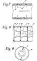
- FIG. 8 An alternatively shaped baffle arrangement is shown in figures 8, 9, and 15-17 .
- conical or windsock-shaped baffles 43 are attached by a fixation device 44 on the interior surface of the tube.
- the windsock baffles 43 can be made of a material which may be woven or formed of a resilient material such as rubber or resilient plastic. The material may be of such a nature that it may collapse onto the surface of the item being moved through it while at the same time allowing the item to advance with minimal impedance.
- These interior windsocks 43 can be spaced apart from one another such that the item, on leaving one windsock baffle 43, will at that moment be delivered into the next overlapping windsock baffle 43 in the series as particularly suggested in figure 8 , thus maintaining a continuous seal as the item moves down the tube.
- baffles 50 may have a disc shape as suggested in figure 30 , or it may have a generally conical shape, as suggested in figure 31 . This conical shape will help orient the moving object in the central axis of the tube and baffle.
- the baffles 50 may have a modified conical shape as suggested in figure 32 . This shape may provide a venturi-like effect to the airflow passing through the baffles 50.
- the disc 50 may have guide plates 54 as suggested in figures 33 and 34 .
- the tubes 40 illustrated here can comprise an outer tube 45 and a coaxial inner tube 46 having apertures 47 therein.
- This tube arrangement permits the creation of an air flow liner 46 thereby facilitating the maintenance of the object moving through the tube in a more central position in the tube 40, while at the same time placing an axially extending air space 48 between individual objects F which may be moving through the tube 40 at the same time. Additionally this arrangement will allow for the effect of either vacuum or positive air pressure applied to the tube to reach more than one item moving through the tube at the same time.
- a retainer ring 60 is shown in figures 10 and 11 , wherein the retainer ring 60 is perforated by peripheral holes 66 which may be of different diameters and either perpendicular to or angled in any direction with relationship to the surfaces of the retainer ring 60. These holes 66 allow for the passage of air from one inter-baffle space to another.
- modified airflow and air pressures within the tubes can be provided by an arrangement of a coaxially aligned outer tube 45 and an inner tube 46 ( figures 10-14 ).
- the toridal-shaped space 48 between the tubes 45 and 46 allows air to be exhausted along the entire length of a tube line.
- Portals 47 can be provided to inject or exhaust air so as to provide the desired positive or negative pressures for urging the objects F along the tubes in accordance with the invention.
- These passages 47 can be formed so as to provide a helical air flow as suggested especially in figure 14 . This helical air flow may discourage the moving objects F from violently impacting the inner tube sides and consequently suffering bruising or other damage.
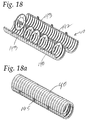
- Tube halves 140, 142 can be formed with mating corrugated shapes 143, and the baffles 50 can be nested at desired spacing within the corrugations as suggested in figure 18 .
- the tube halves can then be assembled and locked together with suitable clamp locks 145 as suggested in figure 18a .
- unitary tubes 40 can be provided with a spiral corrugation 146 as shown in figure 19 , and the spacers 50 can be mounted within the tube by a helical, screwing-like motion.
- Locking tabs 150 can be provided on the baffles 50 to mate with recesses (not shown) within the tube 40 as suggested in figure 19a .
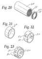
- the tube 40 can be provided with an extended series of threads 155, and the baffles 50 can be provided with mating threads 156, as suggested in figure 20 .
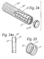
- Spacers 80 can be made of soft material and can be located between the baffles 50. These spacers 80 can be provided with ports 82 ( figures 22 and 23 ). If the tube 40 is made of transparent material such as plastic, these ports 82 can be used to view and inspect the interior of the tube system. Alternatively, these ports 82 can provide the desired airflow if the tube system is provided with the coaxial tube arrangement described above. See figure 24 . If desired, these spacers and baffles can be made as a single unit. See figure 24a . To mate with a helically corrugated tube, this spacer may be provided with a spring-like helix member 85 as suggested in figure 25 .
- FIG. 26 An alternatively designed spacer 87 is shown in figure 26 .
- This spacer is formed of soft, pliable material which will conform to the inner surface of a tube, whether corrugated or planer. Spaced apart arms 88 prevent the transported object from colliding with the rigid tube wall, but the spacing between these items 88 minimizes impedance to object travel.
- Figures 27 - 29 suggest one of several known arrangements for interconnecting tube length modules.
- the tube sections can be snapped together by hand or with tools to form a flexible tube assembly.
- the joints 90 are self-sealing but slide to provide flexibility.
- a series of transport tubes can be carried within a relatively large conduit 400, as suggested in figure 35 .
- the conduit 400 can be equipped with a delivery chute 35 so that the picker can place objects of varying sizes in tubes of appropriate and corresponding diameter.
Description
- This application claims priority from
U.S. provisional patent application 60/920,069 filed March 26, 2007 U.S. provisional patent application serial number 60/949,630 filed July 13, 2007 - This invention relates generally to systems for transporting small objects, and more particularly relates to pneumatic transport systems.
- Presently in the fruit industry, most specifically in the apple industry, fruit is traditionally handpicked. The pickers carefully place the fruit in apple bags which are worn on the shoulders of the pickers, extending downward over the chest and abdomen to the groin. The pickers then gently release the fruit into large bins for later transport to a packing or processing plant. This technique provides for the "on-tree" selection by the picker of the appropriate fruit (apples) for picking utilizing the visually discernible criteria of color size and quality. Good pickers remove the fruit from the tree while keeping the stem intact on the fruit so as to maintain the integrity of the following years fruiting bud on the tree. On occasion, the picking operations must contend with the clipping of overly stiff or long stems; the gentle placement of the fruit into the picking bag to prevent bruising; and the transfer and delivery of the fruit to a larger size container better adapted for truck transport. Fruit located on high limbs may require that the picker climb a ladder or stand on a scaffold to reach the fruit. The fruit bins are usually placed in the row between tree lines and spaced so that they can be filled by apples transferred from the picker's bag within the shortest walking distance. The bins are then picked up by an apple trailer pulled by a tractor and taken to a common holding site awaiting forklift placement onto a flatbed truck.
- This fruit picking process results in about 30% of the picker's time actually picking fruit, with the remaining 70% of the time gently placing the fruit into bags or bins after having clipped the stems when required, moving and climbing up and down ladders, carrying fruit from one place to another, then walking to and carefully releasing the picker's bag load of apples into the collecting bin taking special care not to cause a blemish or bruise on the fruit by rough handling. The picker's bag load may weigh 40 pounds or more leading to fatigue of the picker and a reduction in efficiency.
- Due to the seasonal nature of the fruit harvest, fruit pickers are frequently found amongst migrant worker groups often from countries outside the United States. As a result of stringent U.S. immigration policies, a sufficient numbers of pickers may not be available to pick the fruit at harvest time. Due to the slowness of the fruit handpicking process, large numbers of pickers are required when the fruit reaches the proper point of ripeness. Since individual productivity is low when fruit is handpicked, wages remain low for the individual picker. This in turn results in the propagation of a population of below average wage earners.
- It is an objective of this invention to improve the productivity of the individual picker while maintaining the advantages of the hand picking process, namely: selectivity of fruit to be picked, gentleness to prevent bruising at all stages of movement and packing and stem trimming when needed is desirable.
- To accomplish this objective, a system involving specially modified and augmented pneumatic tubes is presented.
-
US-A-4558561 discloses: A mechanical fruit picker includes a vacuum-operated picking tube which is operably mounted to a tractor and which is designed to pick and deliver fruit to a trailer pulled behind the tractor. The vacuum in the tube is created by a blower mounted to the power take-off of the tractor, while foam rubber paddles are provided within the tube to slow the movement and thus prevent bruising of the fruit. An operator using the tube stands on a platform which is hydraulically adjustable in both horizontal and vertical directions and which is mounted on the top of the tractor. The tube is selectively retractible and extensible at both ends so as to facilitate the picking of fruit in difficult to reach locations and to control the distance that the fruit must fall into the fruit storage trailer. The trailer must be lined with foam rubber to further lessen the likelihood of the fruit damage during the picking operation. - According to one aspect of the present invention there is provided a device for transporting articles, comprising: a tube adapted to receive and transport an article; a plurality of resiliently deformable baffles at spaced-apart locations along the length of the tube; each baffle defining an aperture through which the article can pass, and being adapted to make a temporary pneumatic seal when it at least partly engages the surface of an article in the aperture; and a pneumatic system to develop a pressure differential across the baffle throughout the time of engagement of the article in the aperture to pull or push an article from the baffle and advance it to the next baffle along the full length of the baffle segmented tube to move the article and sequentially engages the baffles through the tube.
- According to a second aspect of the present invention there is provided a method of transporting an article through a tube having resiliently deformable baffles therein, each baffle defining an aperture through which the transported article can pass, the baffles being spaced apart along the length of the tube and arranged to at least partly engage the surface of an article in the aperture so as to make a temporary pneumatic seal, the method comprising the steps of: receiving an article in a tube upstream end; creating a pressure differential across the baffle throughout the time of engagement of the article in the aperture along the full length of the baffle segmented tube so as to pull or push the article from the baffle and advance it to the next baffle to cause the articles to move and sequentially engage the baffles through said tube; and depositing an article in a predetermined location after the article is delivered to a downstream tube end.
-
-
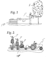
Figure 1 is an elevational view showing an exemplary apple picker who is picking apples from a tree and depositing the apples in an embodiment of the invention for transport to an apple collection bin. -
Figure 2 is an elevational view showing a tractor and trailer upon which are mounted apple picking stations being used by apple pickers who are depositing the picked apples in an embodiment of the invention for transport to an apple collection bin. -
Figure 3 is an elevational view similar toFigure 1 but showing typical apple pickers and a trailer as they appear from the rear of the trailer. -
Figure 3a is an elevational view showing a typical apple picker and his apple picking station, and suggesting how the station can be moved relative to the platform upon which the station is mounted. -
Figure 4 is an elevational view of a typical baffle found within a transport tube. -
Figure 5 is a sectional view of a typical transport tube and, mounted therein, the baffles ofFigure 4 . -
Figure 6 is a sectional view of a typical transport tube similar toFigure 5 but showing resilient material mounted between the baffles. -
Figure 7 is a sectional view similar tofigure 6 but showing a different form of resilient material mounted between the baffles -
Figure 8 is a sectional view similar toFigures 5, 6 and7 showing a typical conical or windsock-shaped baffle. -
Figure 9 is an elevational view of the baffle shown infigure 8 . -
Figure 10 is an elevational view of an alternate form of a baffle. -
Figure 11 is a fragmentary view showing, in section, an alternate arrangement of the tube and baffles shown inFigures 7 or 8 and 10 . -
Figure 12 is an enlarged fragmentary view showing in further detail the arrangement of a baffle and air holes shown inFigure 11 . -
Figure 13 is a fragmentary sectional view showing an embodiment of the invention including an outer tube, an inner transport tube, air movement spaces between the tubes, and baffles. -
Figure 14 is a sectional view of the tube and baffle arrangement shown infigure 13 . -
Figure 15 is a fragmentary view in partial section suggesting the movement of typical objects such as apples through the inventive tube and baffles. -
Figure 16 is an elevational view showing a baffle of the type included in the tube shown infigure 15 . -
Figure 17 is a fragmentary view in sectional aspect showing conical or windsock baffles within the transport tube. -
Figure 18 is an isometric view showing how one embodiment of the transport tube and baffles can be assembled. -
Figure 18a is an isometric view showing the tube offigure 18 in its assembled configuration. -
Figure 19 is in isometric view similar tofigure 18 but showing how another embodiment of the transport tube and baffles can be assembled. -
Figure 19a is an isometric view similar tofigure 19 but showing how yet another embodiment of the transport tube and baffles can be assembled. -
Figure 20 is in isometric view similar tofigures 18 and19 showing how still another embodiment of the transport tube and baffles can be assembled. -
Figure 21 is an isometric view showing a spacer which can be positioned between adjacent baffles. -
Figure 22 is an isometric view similar tofigure 21 but showing a spacer provided with two exhausts or viewing ports. -
Figure 23 is an isometric view similar tofigure 22 but showing a spacer provided with multiple exhausts or viewing ports. -
Figure 24 is an isometric exploded view showing the tube, spacers and baffles shown infigures 19-23 . -
Figure 24a is an elevational view showing a combination spacer and baffle of the type shown infigure 24 . -
Figure 25 is an isometric view of yet another spacer. -
Figure 26 is isometric view showing still another spacer. -
Figure 27 is a fragmentary sectional view suggesting a structural arrangement which can be used to interconnect various tube sections. -
Figure 28 is an elevational view of an air exhaust venturi mechanism. -
Figure 29 is a fragmentary sectional view of a portion offigure 28 . -
Figure 30 is a sectional view of a disk-shaped baffle. -
Figure 31 is a sectional views similar tofigure 30 but showing a conically shaped baffle. -
Figure 32 is a sectional view similar tofigures 30 and 31 but showing another embodiment of the conical baffle. -
Figure 33 is a sectional view similar tofigures 30-32 but showing yet another embodiment of the baffle. -
Figure 34 is an elevational view of the baffle shown infigure 33 . -
Figure 35 is a fragmentary elevational view showing yet another embodiment of the transport tube and an associated input device. - While the invention will be described in connection with a preferred embodiment and procedure, it will be understood that it is not intended to limit the invention to this embodiment or procedure. On the contrary, it is intended to cover all alternatives, modifications and equivalents as may be included within the scope of the invention as defined by the appended claims.
- In one embodiment, the transport tube invention and its peripheral equipment are comprised of four parts or subsystems. These four subsystems act together to:
- a)surround and contain a selected fruit on the tree, vine or bush; b) release the fruit or other object from the parent tree or plant at the stem's natural point of release or by clipping the stem at a desired length; c) advance (move) the fruit gently yet quickly up and/or down and/or along a rigid or flexible tube pathway, and finally; d) deposit the fruit without bruising into a separate chamber, e.g., a water bath or rigid container.
- a) In the "surround and contain" or entry portion of the device, a
pneumatic tube 40 is provided with a rigid or flexible entry portal or input device 35 (figure 35 ) comprised of plastic, rubber or other suitable material. Thisentry device 35 can be of known design, or it can be a flexible drop chute as disclosed and informally claimed in co-pendingU.S. provisional patent application 60/972,302 filed September 14, 2007 portal device 35 is placed under and around the fruit from the stemless end to the stem end (figs. 1-3 ). When the fruit is picked and separated from the tree, theportal device 35 receives the fruit from the picker and delivers it to the transport tube 40 (figures 1-3, 3a ). The surroundingchute structure 35 is dimensioned so as to allow entry by any given fruit of any size, is stiff enough so as to not collapse or disfigure the shape of thetube 40 by the weight or shape of the fruit throughout the course of its passage, or prolong the passage of the fruit through the hollow chute and tube structure. - b) The fruit or other objects to be picked are separated from the tree by hand, or with the aid of a clipper or scissors-like device. These scissors or clippers can be of known design, or they can be of the sort disclosed and informally claimed in
U.S. provisional patent application serial number 60/921,707 filed April 4, 2007 U.S. provisional patent application serial number 60/949,533 filed July 13, 2007 entry portal 35, and the fruit drops down the tube for transport. In another embodiment of the "release or clip" portion of the device the blade members may be sharp and act like a knife to cut the stem at the desired length. In still another embodiment of the "release or clip" portion of the device, multiple blades may act as a scissor to cut the stem. The rotatable blades may be activated by either a visual/manual system or by a mechanical or electronic sensor when the fruit is properly positioned for fruit stem release from the tree stem. The rotatable blades may be powered by manual force, or pneumatic or other mechanically or hydraulically applied mechanisms.
The fruit can be picked by hand, of course - a lateral force sufficient to break the fruit portion of the stem from the tree can be manually applied. - c) In the "advance/move" portion of the device, the interior of the hollow or
tubular portion 40 of the device can be lined with a soft or readily insertible and replaceable material liner 41 (figure 6 ), and a series of baffles, as more extensively disclosed and claimed below. Pneumatic pressure can be applied to the fruit or other object to be moved, as more fully described and claimed below. - d) The terminal downstream peripheral "deposit portion" of the tube is configured so as to gently deliver the fruit or other objects into either a water bath or rigid container. The tube downstream end may be directed to different location in a water bath(not shown) by hand or machine, or the
tube 40 can be rigidly connected to the water bath container for delivery into a sufficiently deep current of water so that any particular fruit does not contact another fruit or the bottom of the container during the water entry process. In a first embodiment of the "deposit portion" of the device, the terminal portion of the tube is connected to a water bath container. In a second embodiment, the "deposit end" of the device is arranged for delivery of the fruit or other items into a rigid container or water bath, but a terminal baffle or cushion of soft material or inflatable material is positioned so as to absorb the force of the moving fruit without bruising it. Once decelerated, the fruit would exit the flexible tube through a lateral portal, either by moving the tube away from the direction of the fruit exit portal, or by gently pushing the fruit through the portal in the tube side. This pushing action could be provided by an inflatable device triggered mechanically, or it could be triggered electrically by the fruit hitting a terminal deceleration cushion.
- a) In the "surround and contain" or entry portion of the device, a
- In 19th-century Europe, public and technical interest arose in the idea of so-called atmospheric railways. Original proposals called for the use of pneumatic tubes to carry letters, packages and even passenger trains, cars and freight. The train might be thought of as a series of car capsules or canisters into which people or items of an undetermined shape entered before being moved along as a result of an exterior force applied to the train cars. If a seal were to be created between the canister cars and the interior surface of the tunnel, the canister cars could be moved through the tube by providing relatively low pneumatic pressure at the forward end of the train and a relatively high pneumatic pressure at the rear end of the train. Later proposals suggested the use of a small pneumatic tube located alongside an ordinary railway track; a piston inside the tube would pull an attached train running on the rails. The ultimately successful alternative of pulling railway trains through tunnels or tubes behind steam locomotives was extensively developed during the same years. See: http://www.columbia.edu/∼brennan/beach/- chapter 2.html.
- In 1840, Samuel Clegg and Jacobs Samuda (British subjects) obtained
U.S. Patent No. 1,922 for the Construction of Valves for Pneumatic Railways. Implementation of that patent led to the successful movement of a train on wheels on a track positioned within a tube for a distance of one block.U.S. Patent Nos. 255, 525 and284, 456 disclose early pneumatic systems for so-called store service carriers. - The fundamental concept common to previous pneumatic systems for movement of items relies on one or more seal members affixed to the moving item. These seal members provide a pneumatic seal between the moving item and the interior surface of the tube. The item to be transported (which may be of any shape) is placed within a canister of predetermined shape. An exterior flange-like seal secured to the canister moves along with the canister through the tube. The seal continuously engages the interior surface of the tube so as to provide an air seal. This air seal permits the development of a pneumatic pressure differential in the tube between the upstream and downstream surfaces of the seal and capsule. The force of this air pressure differential propels the capsule and seal along the tube.
- The object of this invention is to rapidly move items through a tube independent of the items' shapes without having to place the items into a capsule or canister of fixed shape. A means to create a seal sufficient to allow the pressurized system to advance the item through the tube is required. An embodiment of the new concept focuses on a sealing arrangement, but the seals do not move along through the tube. The sealing arrangement nevertheless can maintain a proper environment for effectively providing pneumatically induced movement of the item through the tube.
- In accordance with the invention, a series of sealing baffles are affixed to the interior wall of the tube and can accommodate items of different sizes and shapes while maintaining a series of pneumatic seals between the sealing baffles and the items moving down the tube.
- As suggested in
figures 1-3 and 3a , this pneumatic tube system can be used by individual pickers P. Each picker can have aninput chute 35, which can be located adjacent the picker's chest. Thechute 35 leads to apneumatic tube 40 which transports the picked fruit to abin 140 or other collection device. If desired, the tube transport system and the pickers P can be mounted on atrailer 240 pulled by a tractor T as shown infigure 2 . Alternatively, the systems and pickers can be mounted on a self-propelled vehicle as indicated in co-pendingU.S. provisional patent application serial number 60/026,351 filed February 13, 2008 . Or the systems can be mounted on a sled, a movable frame, or even a stationary pad. - To reach apples or other fruit at various heights in the trees, the pickers P can be provided with picking stations or
platforms 340 as especially suggested infigure 3a . The positions of thesestations 340 can be adjusted by known hydraulic or other systems as suggested by the arrows infigure 3a . - As shown in
figures 4-12 and elsewhere, one embodiment of the invention comprises atube 40 which may be rigid or flexible and made of plastic, metal or other suitable material. The tube can be of circular, and/or any convenient cross-sectional shape. In accordance with the invention, a series of sealing baffles 50 are provided at spaced apart locations within the interior of the tube. Each baffle is affixed to the interior of thetube 40, is aligned in a perpendicular fashion relative to the tube axis, and is made of a resilient smooth-surface material such as a silicon rubber or resilient plastic. Preferably, the spacing between thebaffles 50 is selected to be approximately the same as the major dimension of the items to be moved through the transport tubes. The system will perform but perhaps less effectively if the baffle-to-baffle distance is made to be substantially greater or less than this item's major dimension. - In an alternative embodiment of the invention, groups of closely-spaced multiple baffles may be located at major intervals along the tube interior.
- Preferably, the baffles each define a central opening or
hole 51. The outer periphery of the baffle, and the periphery of thehole 51, can be of any convenient shape such as circular, oval, elliptical, or other shape. As suggested infigure 15 , thecentral opening 51 is of such diameter that an item F greater in diameter than thehole 51 but lesser in diameter than the tube can pass through the tube because of the elasticity of thebaffle 50. Thebaffle 50 may haveslits 52 extending from the central opening into the baffle material to facilitate its opening to accommodate a relatively loose item F passing through it. If small items F are to be moved, theslits 52 may not be needed. Alternatively, thebaffles 50 can be inflatable. The material comprising the inflatable baffles can be shaped and arranged so that progressive inflation of the baffle will provide a progressivelysmaller opening 51, or the shape of theopening 51 will be progressively changed in some other way. - Throughout the time of engagement of the item in the central opening of the baffle, a more or less imperfect pneumatic seal is temporarily made between the object and the baffle surface. When the pneumatic system (vacuum or air pressure) pulls or pushes it free from an upstream baffle, the item rapidly advances to the next baffle opening where the phenomenon is repeated for the full length of the baffle segmented tube.
- To minimize any traumatic effect on the item F being moved through the
tube 40 in further accordance with the invention, the interior of the tube surface located between the resilientperiodic baffle members 50 may be lined with asoft material 41 such as a soft rubber or resilient plastic. Alternatively, a series of many soft cushions such as outcroppings of small flexible finger-like extensions 42 or a soft inflatable air-filled balloon-like interior wall liner can be provided between the baffles as particularly suggested infigure 6, 7 and 24-26 . - An alternatively shaped baffle arrangement is shown in
figures 8, 9, and 15-17 . There, conical or windsock-shapedbaffles 43 are attached by afixation device 44 on the interior surface of the tube. The windsock baffles 43 can be made of a material which may be woven or formed of a resilient material such as rubber or resilient plastic. The material may be of such a nature that it may collapse onto the surface of the item being moved through it while at the same time allowing the item to advance with minimal impedance. Theseinterior windsocks 43 can be spaced apart from one another such that the item, on leaving onewindsock baffle 43, will at that moment be delivered into the next overlappingwindsock baffle 43 in the series as particularly suggested infigure 8 , thus maintaining a continuous seal as the item moves down the tube. - Several variations of these
baffles 50 are shown infigures 30-34 . Thebaffles 50 may have a disc shape as suggested infigure 30 , or it may have a generally conical shape, as suggested infigure 31 . This conical shape will help orient the moving object in the central axis of the tube and baffle. Alternatively, thebaffles 50 may have a modified conical shape as suggested infigure 32 . This shape may provide a venturi-like effect to the airflow passing through thebaffles 50. Thedisc 50 may haveguide plates 54 as suggested infigures 33 and34 . - The
tubes 40 illustrated here can comprise anouter tube 45 and a coaxialinner tube 46 havingapertures 47 therein. This tube arrangement permits the creation of anair flow liner 46 thereby facilitating the maintenance of the object moving through the tube in a more central position in thetube 40, while at the same time placing an axially extendingair space 48 between individual objects F which may be moving through thetube 40 at the same time. Additionally this arrangement will allow for the effect of either vacuum or positive air pressure applied to the tube to reach more than one item moving through the tube at the same time. - Other means of achieving similar effect(s) can be accomplished by having air movement portals periodically and circumferentially placed in the tube. As suggested in
figures 9-12 and elsewhere, peripheral air movement occurs through thespace 48 between theouter tube 45 and the baffle-containinginner tube 46 while at the same time central air movement is occurring through theinner tube 46. These portals may be of the same or different diameters, and aligned either perpendicular to the inner tube surface or at the same or varied angles to achieve the desired effect(s). Thetubes - A retainer ring 60 is shown in
figures 10 and 11 , wherein the retainer ring 60 is perforated by peripheral holes 66 which may be of different diameters and either perpendicular to or angled in any direction with relationship to the surfaces of the retainer ring 60. These holes 66 allow for the passage of air from one inter-baffle space to another. - As suggested above, modified airflow and air pressures within the tubes can be provided by an arrangement of a coaxially aligned
outer tube 45 and an inner tube 46 (figures 10-14 ). The toridal-shapedspace 48 between thetubes Portals 47 can be provided to inject or exhaust air so as to provide the desired positive or negative pressures for urging the objects F along the tubes in accordance with the invention. Thesepassages 47 can be formed so as to provide a helical air flow as suggested especially infigure 14 . This helical air flow may discourage the moving objects F from violently impacting the inner tube sides and consequently suffering bruising or other damage. - The construction and assembly of the tubes, battles and inner liners or spacers is suggested in
figures 18-26 . Tube halves 140, 142, can be formed with mating corrugated shapes 143, and thebaffles 50 can be nested at desired spacing within the corrugations as suggested infigure 18 . The tube halves can then be assembled and locked together with suitable clamp locks 145 as suggested infigure 18a . Alternatively,unitary tubes 40 can be provided with aspiral corrugation 146 as shown infigure 19 , and thespacers 50 can be mounted within the tube by a helical, screwing-like motion. Lockingtabs 150 can be provided on thebaffles 50 to mate with recesses (not shown) within thetube 40 as suggested infigure 19a . In yet another alternative arrangement, thetube 40 can be provided with an extended series ofthreads 155, and thebaffles 50 can be provided withmating threads 156, as suggested infigure 20 . - Spacers 80 (
figure 21 ) can be made of soft material and can be located between thebaffles 50. Thesespacers 80 can be provided with ports 82 (figures 22 and 23 ). If thetube 40 is made of transparent material such as plastic, theseports 82 can be used to view and inspect the interior of the tube system. Alternatively, theseports 82 can provide the desired airflow if the tube system is provided with the coaxial tube arrangement described above. Seefigure 24 . If desired, these spacers and baffles can be made as a single unit. Seefigure 24a . To mate with a helically corrugated tube, this spacer may be provided with a spring-like helix member 85 as suggested infigure 25 . - An alternatively designed
spacer 87 is shown infigure 26 . This spacer is formed of soft, pliable material which will conform to the inner surface of a tube, whether corrugated or planer. Spaced apartarms 88 prevent the transported object from colliding with the rigid tube wall, but the spacing between theseitems 88 minimizes impedance to object travel. -
Figures 27 - 29 suggest one of several known arrangements for interconnecting tube length modules. The tube sections can be snapped together by hand or with tools to form a flexible tube assembly. Thejoints 90 are self-sealing but slide to provide flexibility. - If desired, a series of transport tubes can be carried within a relatively
large conduit 400, as suggested infigure 35 . Theconduit 400 can be equipped with adelivery chute 35 so that the picker can place objects of varying sizes in tubes of appropriate and corresponding diameter.
Claims (14)
- A device for transporting articles (F), comprising:a tube (40) adapted to receive and transport an article;a plurality of resiliently deformable baffles (50) at spaced-apart locations along the length of the tube;each baffle defining an aperture (51) through which the article can pass, characterised in that each baffle is adapted to make a temporary pneumatic seal when it at least partly engages the surface of an article (F) in the aperture; anda pneumatic system to develop a pressure differential across the baffle throughout the time of engagement of the article in the aperture to pull or push the article from the baffle and advance it to the next baffle along the full length of the baffle segmented tube to move the article and sequentially engages the baffles through the tube.
- A device according to claim 1 wherein the aperture (51) is arranged to permit the article (F) to engage and deform the baffle and aperture so as to permit the article to move through the aperture.
- A device according to claim 1 wherein adjacent baffles are spaced apart by a distance approximately equal to the diameter of the baffle aperture.
- A device according to claim 1 wherein the baffles (50) are arranged such that a plurality of baffles is substantially continuously engaged by an article as the article moves through the tube.
- A device according to claim 1 further including a cutter for separating the article (F) from a plant.
- A device according to claim 1 further including means for depositing the article (F) in a predetermined location after the article is delivered to a downstream end of the tube (40).
- A device according to claim 1 wherein said tube member (40) comprises an outer tube (45) and an inner tube (46) coaxially aligned with but radially spaced apart from the outer tube (45) to provide an air flow space (48) between the inner (46) and outer tubes (45).
- A device according to claim 1 further including at least one liner member (41) located between adjacent baffles.
- A device according to claim 1 wherein the device is mounted upon a 3 mobile platform (340).
- A device according to claim 1 further including a chute (35) mounted at an entry end of said tube (40), the chute being adapted to receive an article (F) to be transported and to deliver the article to the entry end of said tube.
- A device according to claim 1 further including means for decelerating the transported article at the exit end of the tube (40).
- A device according to claim 1 further including a water bath (140) for transported articles emanating from the tube (40).
- A device according to claim 1 wherein the plurality of deformable baffles (50) is of generally either conical shape and having axial lengths of predetermined extent, or disk shaped having an axial dimension less than its radial dimension, or planar ring shaped.
- A method of transporting an article (F) through a tube (40) having resiliently deformable baffles (50) therein, each baffle defining an aperture (51) through which the transported article can pass, the baffles (50) being spaced apart along the length of the tube (40) and arranged to at least partly engage the surface of an article (F) in the aperture (51) so as to make a temporary pneumatic seal, the method comprising the steps ofreceiving an article in a tube upstream end;creating a pressure differential across the baffle throughout the time of engagement of the article in the aperture along the full length of the baffle segmented tube (40) so as to pull or push the article from the baffle and advance it to the next baffle to cause the articles to move and sequentially engage the baffles through said tube (40); anddepositing an article in a predetermined location after the article is delivered to a downstream tube end.
Applications Claiming Priority (3)
| Application Number | Priority Date | Filing Date | Title |
|---|---|---|---|
| US92006907P | 2007-03-26 | 2007-03-26 | |
| US94963007P | 2007-07-13 | 2007-07-13 | |
| PCT/US2008/058151 WO2008118915A1 (en) | 2007-03-26 | 2008-03-25 | Transport system for fruit and like objects |
Publications (3)
| Publication Number | Publication Date |
|---|---|
| EP2134154A1 EP2134154A1 (en) | 2009-12-23 |
| EP2134154A4 EP2134154A4 (en) | 2011-11-23 |
| EP2134154B1 true EP2134154B1 (en) | 2016-03-16 |
Family
ID=39788998
Family Applications (1)
| Application Number | Title | Priority Date | Filing Date |
|---|---|---|---|
| EP08799697.1A Not-in-force EP2134154B1 (en) | 2007-03-26 | 2008-03-25 | Transport system for fruit and like objects |
Country Status (16)
| Country | Link |
|---|---|
| US (1) | US7695220B2 (en) |
| EP (1) | EP2134154B1 (en) |
| JP (2) | JP5185363B2 (en) |
| CN (1) | CN101677510B (en) |
| AU (1) | AU2008230918B2 (en) |
| BR (1) | BRPI0809424A2 (en) |
| CA (1) | CA2681407C (en) |
| DK (1) | DK2134154T3 (en) |
| ES (1) | ES2576653T3 (en) |
| IL (1) | IL201181A0 (en) |
| MX (1) | MX337506B (en) |
| NZ (1) | NZ580593A (en) |
| PL (1) | PL2134154T3 (en) |
| RU (1) | RU2009137834A (en) |
| WO (1) | WO2008118915A1 (en) |
| ZA (1) | ZA200907335B (en) |
Cited By (1)
| Publication number | Priority date | Publication date | Assignee | Title |
|---|---|---|---|---|
| US11883974B2 (en) | 2019-02-11 | 2024-01-30 | John Bean Technologies Corporation | Pick and throw harvesting |
Families Citing this family (27)
| Publication number | Priority date | Publication date | Assignee | Title |
|---|---|---|---|---|
| NL1030450C2 (en) * | 2005-11-17 | 2007-05-21 | Greefs Wagen Carrosserie | Device and method for the channeled transport of fruits with the aid of a liquid channel. |
| US8371773B2 (en) * | 2007-03-26 | 2013-02-12 | Picker Technologies Llc | Transport system for fruit and like objects |
| JP5833441B2 (en) | 2008-07-31 | 2015-12-16 | ピッカー・テクノロジーズ・リミテッド・ライアビリティ・カンパニーPicker Technologies Llc | Pneumatic tube conveying system for conveying at least one object having a generally irregular shape and method for moving at least one object having a generally irregular shape along a pneumatic tube |
| US20100064653A1 (en) * | 2008-09-16 | 2010-03-18 | Dietrich Charles E | Pneumatic Fruit Decelerator Apparatus and Method |
| GR1006747B (en) * | 2008-11-28 | 2010-04-08 | Χρηστος Κολιουσης | Device for fast fruit gathering |
| CA2750060A1 (en) * | 2009-01-20 | 2010-07-29 | Picker Technologies Llc | Decelerator comprising deceleration tank and extraction conveyor |
| US7810305B2 (en) * | 2009-02-26 | 2010-10-12 | Macidull John C | Automated fruit harvesting apparatus |
| NZ597130A (en) * | 2009-06-15 | 2014-05-30 | Picker Technologies Llc | Dry decelerator for apples or like objects |
| US7926252B2 (en) * | 2009-09-01 | 2011-04-19 | Dbr Conveyor Concepts, Llc | Pneumatic fruit decelerator apparatus and method |
| WO2011129810A1 (en) * | 2010-04-12 | 2011-10-20 | Picker Technologies Llc | Transport system for fruit and like objects |
| CA2765013A1 (en) * | 2010-07-16 | 2010-12-23 | Picker Technologies Llc | Dry decelerator for apples or like objects |
| CA2868108A1 (en) * | 2011-04-06 | 2012-10-11 | Fish Transport Systems, Llc | Object transport tube |
| US8997446B2 (en) | 2011-10-17 | 2015-04-07 | Dbr Conveyor Concepts, Llc | Pneumatic fruit decelerator body |
| WO2014015008A2 (en) * | 2012-07-19 | 2014-01-23 | Lawrence Livermore National Security, Llc | Method and system for target injection using a gas-bearing injection barrel |
| KR101358595B1 (en) | 2012-08-23 | 2014-02-04 | 이홍곤 | Device for harvesting fruit |
| US11272662B2 (en) | 2014-12-03 | 2022-03-15 | Sri International | End effector for robotic harvesting |
| ITUB20151290A1 (en) | 2015-05-28 | 2016-11-28 | Unitec Spa | APPARATUS FOR THE DISTRIBUTION OF FRUIT AND VEGETABLE PRODUCTS. |
| US10005626B2 (en) | 2015-11-18 | 2018-06-26 | Drew P. HENRY | Vacuum laundry chute system |
| EP3500084A4 (en) * | 2016-09-21 | 2020-06-17 | Abundant Robotics, Inc. | Systems for robotic harvesting |
| IT201700099467A1 (en) | 2017-09-05 | 2019-03-05 | Cottlab Ltd | Self-propelled robotic harvester for the selective collection of agricultural crops in high quality rows |
| NZ762548A (en) * | 2017-09-15 | 2022-02-25 | Abundant Robotics Inc | Doubles end-effector for robotic harvesting |
| KR102257804B1 (en) * | 2019-08-27 | 2021-05-28 | 공주대학교 산학협력단 | A air pickers for crop harvesting with automatic cutting function |
| EP4228985A1 (en) * | 2020-10-16 | 2023-08-23 | Kongskilde Industries A/S | A pneumatic conveyor system |
| EP4237359A1 (en) * | 2020-11-02 | 2023-09-06 | Kongskilde Industries A/S | A pneumatic pick up unit and a pneumatic conveyor system |
| CN112830276B (en) * | 2021-01-04 | 2022-10-25 | 南京横溪农业发展有限公司 | Watermelon conveying device |
| CN112903589A (en) * | 2021-04-13 | 2021-06-04 | 塔里木大学 | Apple sugar detection equipment based on Raman spectrum |
| CN114303642B (en) * | 2022-01-19 | 2023-04-11 | 五河县绿色农产品协会 | Efficient grape picking device |
Family Cites Families (68)
| Publication number | Priority date | Publication date | Assignee | Title |
|---|---|---|---|---|
| USRE23524E (en) | 1952-07-22 | Fruit picking device | ||
| US1114318A (en) | 1913-11-19 | 1914-10-20 | Joseph T Vasey | Fruit-gatherer. |
| US1626402A (en) | 1926-04-24 | 1927-04-26 | Fryman Nancy | Fruit picker |
| US2288682A (en) | 1941-01-23 | 1942-07-07 | Irving B Chittenden | Automatic fruit picker |
| US2545072A (en) * | 1948-12-16 | 1951-03-13 | Denman Frank | Fruit picking device |
| US2650464A (en) * | 1950-12-04 | 1953-09-01 | Louis L Bernheim | Fruit picker device |
| US2711625A (en) | 1951-07-09 | 1955-06-28 | Giles E Bullock | Fruit picking apparatus |
| US2680338A (en) | 1953-02-02 | 1954-06-08 | Space Jack | Cotton-picking machine |
| US2775088A (en) * | 1954-12-10 | 1956-12-25 | Giles E Bullock | Fruit picking apparatus |
| US2968907A (en) | 1959-05-18 | 1961-01-24 | Louis L Bernheim | Pneumatic fruit picker |
| US3165880A (en) * | 1961-12-22 | 1965-01-19 | Jr Archie P Buie | Fruit picking and transporting device |
| US3460327A (en) * | 1966-07-11 | 1969-08-12 | Up Right Inc | Apparatus for harvesting fruit |
| US3348647A (en) | 1966-07-18 | 1967-10-24 | Univ California | Fruit depositing device for harvester |
| US3413787A (en) | 1966-08-25 | 1968-12-03 | Frederick W. Van Antwerp | Mechanical fruit picker |
| US3460330A (en) | 1966-10-31 | 1969-08-12 | George L Black Jr | Apparatus for harvesting agricultural crops |
| US3473312A (en) | 1967-01-18 | 1969-10-21 | Frank W Holt | Fruit picker |
| US3507107A (en) | 1968-01-25 | 1970-04-21 | George C Harms | Portable fruit picker |
| US3464529A (en) | 1968-03-04 | 1969-09-02 | Theodore Horsky Jr | Fruit handling device |
| US3489258A (en) * | 1968-04-29 | 1970-01-13 | United States Steel Corp | Pulsating fall retarder |
| US3559387A (en) | 1968-12-02 | 1971-02-02 | Elliott Brothers London Ltd | Fruit picking apparatus |
| US3591949A (en) | 1969-04-17 | 1971-07-13 | Chisholm Ryder Co Inc | Fruit-harvesting machine |
| US3564826A (en) * | 1969-04-21 | 1971-02-23 | Ilc Ind Inc | Article handling apparatus |
| US3538695A (en) | 1969-08-18 | 1970-11-10 | Agtech Systems Corp | Fruit picking device |
| US3584442A (en) * | 1970-02-18 | 1971-06-15 | Ael Food Automation Inc | Method and apparatus for picking citrus fruit |
| US3664104A (en) | 1971-03-24 | 1972-05-23 | Khosrow Jamshidi | Fruits and nuts picking device |
| JPS5031404Y2 (en) * | 1971-08-20 | 1975-09-12 | ||
| JPS501712Y2 (en) * | 1971-09-30 | 1975-01-17 | ||
| US3767268A (en) * | 1971-12-13 | 1973-10-23 | J Stucky | Air conveyor for fowl |
| US3756001A (en) | 1972-05-18 | 1973-09-04 | J Macidull | Fruit harvesting apparatus |
| IL40744A (en) | 1972-11-06 | 1974-12-31 | Rosenberg B | Apparatus for picking fruit growing on trees |
| JPS5138025Y2 (en) * | 1972-12-25 | 1976-09-17 | ||
| US3913307A (en) | 1973-07-19 | 1975-10-21 | Jr Daniel E Cardinal | Vacuum conduit pick-up device |
| US3898785A (en) | 1974-01-25 | 1975-08-12 | Clarence W Chew | Vacuum operated fruit picker |
| US3969878A (en) | 1974-09-05 | 1976-07-20 | Morganeier Herman C | Fruit picking technique |
| US3934691A (en) * | 1974-12-06 | 1976-01-27 | General Electric Company | Ice dispensing system of a refrigerator-freezer |
| US4000602A (en) | 1975-09-29 | 1977-01-04 | Cardinal Jr Daniel E | Vacuum conduit pick-up device with improved control |
| JPS53159953U (en) * | 1977-05-23 | 1978-12-14 | ||
| US4320995A (en) | 1980-03-21 | 1982-03-23 | The United States Of America As Represented By The Secretary Of Agriculture | Vacuum-operated produce handling systems |
| JPS5733128U (en) * | 1980-08-05 | 1982-02-22 | ||
| US4674265A (en) | 1981-06-09 | 1987-06-23 | Gerber Curtis E | Fruit harvesting machine |
| US4388798A (en) | 1981-06-09 | 1983-06-21 | Gerber Curtis E | Fruit harvesting machine |
| US4501113A (en) | 1981-06-09 | 1985-02-26 | Gerber Curtis E | Fruit harvesting machine |
| US4394259A (en) | 1981-10-27 | 1983-07-19 | Temco, Inc. | Vacuum pneumatic conveying apparatus and method for transferring food products |
| US4491212A (en) | 1982-07-28 | 1985-01-01 | Gray Jr Frank L | Picker's aid |
| JPS5931614A (en) * | 1982-08-11 | 1984-02-20 | 株式会社クボタ | Fruit harvesting apparatus |
| JPS59120013A (en) * | 1982-12-28 | 1984-07-11 | 月星化成株式会社 | Slow transfer tool of fruits |
| US4558561A (en) | 1983-08-26 | 1985-12-17 | Mendenhall Harold P | Mechanical fruit picker |
| US4524573A (en) * | 1984-02-13 | 1985-06-25 | Kinney David J | Vacuum finger harvester for strawberries or the like |
| JPS61283386A (en) * | 1985-06-07 | 1986-12-13 | 井関農機株式会社 | Fruit selector |
| JPS62168010U (en) | 1986-04-11 | 1987-10-24 | ||
| US4704851A (en) | 1986-04-22 | 1987-11-10 | Technion Research & Development Foundation | Agricultural transport system |
| JPS63251687A (en) * | 1987-04-08 | 1988-10-19 | 鳥居化成有限会社 | Corrugated pipe |
| US5007772A (en) * | 1988-10-24 | 1991-04-16 | Mckenna Frank J | Fruit harvesting machine |
| US5205677A (en) * | 1988-10-24 | 1993-04-27 | Kathleen McKenna | Fruit harvesting machine |
| US5125223A (en) | 1990-08-23 | 1992-06-30 | Harvesting Systems, Ltd. | Harvesting apparatus and method |
| US5280697A (en) | 1991-07-30 | 1994-01-25 | Mark Miller | Manual fruit picker |
| US5319911A (en) | 1992-05-26 | 1994-06-14 | Wilhite Russell J | Nut harvester |
| US5599157A (en) | 1994-07-05 | 1997-02-04 | Ellington; Robert | Center-loading harvester |
| AUPN006994A0 (en) | 1994-12-16 | 1995-01-19 | Cernusco, Lawrence Ronald | Apparatus for picking fruit |
| US5840102A (en) | 1996-04-01 | 1998-11-24 | Mccracken; Hilton G. | Mobile pneumatic material transfer machine |
| US6827529B1 (en) | 1998-08-03 | 2004-12-07 | Lancer Ice Link, Llc | Vacuum pneumatic system for conveyance of ice |
| US6371711B1 (en) * | 1999-03-19 | 2002-04-16 | Integrated Environmental Technologies, Llc | Valveless continuous atmospherically isolated container feeding assembly |
| AUPP980099A0 (en) * | 1999-04-16 | 1999-05-13 | Futurepump Ltd | Pneumatic collection and/or conveying method and apparatus |
| US6182431B1 (en) * | 1999-08-06 | 2001-02-06 | Bruce A. Balchen | Fruit picking apparatus |
| FR2808788B1 (en) * | 2000-05-09 | 2002-09-27 | Pescia Antonio Crovara | FORCED IMMERSION HANDLE OF AN ARTICLE |
| JP4001033B2 (en) * | 2003-03-03 | 2007-10-31 | 三菱マテリアルテクノ株式会社 | Air transfer device |
| US20050172595A1 (en) | 2004-02-09 | 2005-08-11 | Wells James R. | Pneumatic raisin harvester |
| WO2008008972A2 (en) | 2006-07-13 | 2008-01-17 | George Gray | Self propelled robotic fresh fruit picker |
-
2008
- 2008-03-25 JP JP2010501166A patent/JP5185363B2/en not_active Expired - Fee Related
- 2008-03-25 PL PL08799697.1T patent/PL2134154T3/en unknown
- 2008-03-25 AU AU2008230918A patent/AU2008230918B2/en not_active Ceased
- 2008-03-25 EP EP08799697.1A patent/EP2134154B1/en not_active Not-in-force
- 2008-03-25 DK DK08799697.1T patent/DK2134154T3/en active
- 2008-03-25 MX MX2009010198A patent/MX337506B/en active IP Right Grant
- 2008-03-25 BR BRPI0809424-1A2A patent/BRPI0809424A2/en not_active IP Right Cessation
- 2008-03-25 WO PCT/US2008/058151 patent/WO2008118915A1/en active Search and Examination
- 2008-03-25 US US12/055,209 patent/US7695220B2/en not_active Expired - Fee Related
- 2008-03-25 RU RU2009137834/21A patent/RU2009137834A/en not_active Application Discontinuation
- 2008-03-25 ES ES08799697.1T patent/ES2576653T3/en active Active
- 2008-03-25 NZ NZ58059308A patent/NZ580593A/en not_active IP Right Cessation
- 2008-03-25 CA CA2681407A patent/CA2681407C/en not_active Expired - Fee Related
- 2008-03-25 CN CN2008800176552A patent/CN101677510B/en not_active Expired - Fee Related
-
2009
- 2009-09-24 IL IL201181A patent/IL201181A0/en unknown
- 2009-10-20 ZA ZA2009/07335A patent/ZA200907335B/en unknown
-
2012
- 2012-11-21 JP JP2012254832A patent/JP5667151B2/en not_active Expired - Fee Related
Cited By (1)
| Publication number | Priority date | Publication date | Assignee | Title |
|---|---|---|---|---|
| US11883974B2 (en) | 2019-02-11 | 2024-01-30 | John Bean Technologies Corporation | Pick and throw harvesting |
Also Published As
| Publication number | Publication date |
|---|---|
| JP5185363B2 (en) | 2013-04-17 |
| WO2008118915A1 (en) | 2008-10-02 |
| CN101677510A (en) | 2010-03-24 |
| ZA200907335B (en) | 2010-11-24 |
| ES2576653T3 (en) | 2016-07-08 |
| BRPI0809424A2 (en) | 2014-09-09 |
| JP2013047149A (en) | 2013-03-07 |
| IL201181A0 (en) | 2010-05-17 |
| WO2008118915A9 (en) | 2009-01-15 |
| AU2008230918B2 (en) | 2016-03-10 |
| US20080279640A1 (en) | 2008-11-13 |
| MX2009010198A (en) | 2009-12-15 |
| RU2009137834A (en) | 2011-05-10 |
| JP5667151B2 (en) | 2015-02-12 |
| AU2008230918A1 (en) | 2008-10-02 |
| MX337506B (en) | 2016-03-09 |
| NZ580593A (en) | 2012-09-28 |
| EP2134154A4 (en) | 2011-11-23 |
| EP2134154A1 (en) | 2009-12-23 |
| US7695220B2 (en) | 2010-04-13 |
| PL2134154T3 (en) | 2016-11-30 |
| DK2134154T3 (en) | 2016-07-04 |
| CN101677510B (en) | 2012-05-02 |
| JP2010522682A (en) | 2010-07-08 |
| CA2681407C (en) | 2017-07-11 |
| CA2681407A1 (en) | 2008-10-02 |
Similar Documents
| Publication | Publication Date | Title |
|---|---|---|
| EP2134154B1 (en) | Transport system for fruit and like objects | |
| US8371773B2 (en) | Transport system for fruit and like objects | |
| US7815401B2 (en) | System for transporting grossly asymmetrical objects such as a cluster of grapes or other fruit through a pneumatic tube | |
| CA2786571C (en) | Pneumatic fruit decelerator apparatus and method | |
| US4394259A (en) | Vacuum pneumatic conveying apparatus and method for transferring food products | |
| US9861037B2 (en) | Mechanical produce harvester with gathering belts | |
| US3953960A (en) | Fruit picking apparatus | |
| US20100064653A1 (en) | Pneumatic Fruit Decelerator Apparatus and Method | |
| CN210352217U (en) | Fruit picker capable of sorting fruits | |
| US20040216441A1 (en) | Onion harvester with leaf topper | |
| WO2011129810A1 (en) | Transport system for fruit and like objects | |
| EP1350422A1 (en) | Mechanized system for collecting olives or the like | |
| WO2000062594A1 (en) | Pneumatic collection and/or conveying method and apparatus | |
| IES64895B2 (en) | A mushroom harvesting aid | |
| CN214493452U (en) | Automatic change high-efficient fruit foam pocket bagging apparatus | |
| EP4000383A1 (en) | Mobile horticulture workstation | |
| US3468110A (en) | Harvesting machine | |
| CN117730699A (en) | Automatic palm fiber removing equipment for palm trees | |
| AU7729598A (en) | Fruit handling apparatus |
Legal Events
| Date | Code | Title | Description |
|---|---|---|---|
| PUAI | Public reference made under article 153(3) epc to a published international application that has entered the european phase |
Free format text: ORIGINAL CODE: 0009012 |
|
| 17P | Request for examination filed |
Effective date: 20091020 |
|
| AK | Designated contracting states |
Kind code of ref document: A1 Designated state(s): AT BE BG CH CY CZ DE DK EE ES FI FR GB GR HR HU IE IS IT LI LT LU LV MC MT NL NO PL PT RO SE SI SK TR |
|
| DAX | Request for extension of the european patent (deleted) | ||
| A4 | Supplementary search report drawn up and despatched |
Effective date: 20111025 |
|
| RIC1 | Information provided on ipc code assigned before grant |
Ipc: A01D 46/24 20060101AFI20111020BHEP Ipc: B65G 69/16 20060101ALI20111020BHEP Ipc: B65G 11/20 20060101ALI20111020BHEP |
|
| 17Q | First examination report despatched |
Effective date: 20120817 |
|
| GRAP | Despatch of communication of intention to grant a patent |
Free format text: ORIGINAL CODE: EPIDOSNIGR1 |
|
| INTG | Intention to grant announced |
Effective date: 20150602 |
|
| GRAS | Grant fee paid |
Free format text: ORIGINAL CODE: EPIDOSNIGR3 |
|
| GRAA | (expected) grant |
Free format text: ORIGINAL CODE: 0009210 |
|
| AK | Designated contracting states |
Kind code of ref document: B1 Designated state(s): AT BE BG CH CY CZ DE DK EE ES FI FR GB GR HR HU IE IS IT LI LT LU LV MC MT NL NO PL PT RO SE SI SK TR |
|
| REG | Reference to a national code |
Ref country code: GB Ref legal event code: FG4D |
|
| REG | Reference to a national code |
Ref country code: CH Ref legal event code: EP |
|
| REG | Reference to a national code |
Ref country code: IE Ref legal event code: FG4D |
|
| REG | Reference to a national code |
Ref country code: AT Ref legal event code: REF Ref document number: 780329 Country of ref document: AT Kind code of ref document: T Effective date: 20160415 |
|
| REG | Reference to a national code |
Ref country code: DE Ref legal event code: R096 Ref document number: 602008042886 Country of ref document: DE |
|
| REG | Reference to a national code |
Ref country code: CH Ref legal event code: NV Representative=s name: NOVAGRAAF INTERNATIONAL SA, CH Ref country code: CH Ref legal event code: PFA Owner name: WHOOSHH INNOVATIONS LLC, US Free format text: FORMER OWNER: PICKER TECHNOLOGIES LLC, US Ref country code: FR Ref legal event code: PLFP Year of fee payment: 9 |
|
| REG | Reference to a national code |
Ref country code: DE Ref legal event code: R082 Ref document number: 602008042886 Country of ref document: DE Representative=s name: PATENTANWAELTE EINSEL & KOLLEGEN, DE Ref country code: DE Ref legal event code: R081 Ref document number: 602008042886 Country of ref document: DE Owner name: WHOOSHH INNOVATIONS LLC, SEATTLE, US Free format text: FORMER OWNER: PICKER TECHNOLOGIES LLC, MERCER ISLAND, WASH., US |
|
| REG | Reference to a national code |
Ref country code: DK Ref legal event code: T3 Effective date: 20160624 |
|
| REG | Reference to a national code |
Ref country code: SE Ref legal event code: TRGR |
|
| REG | Reference to a national code |
Ref country code: NL Ref legal event code: FP |
|
| REG | Reference to a national code |
Ref country code: ES Ref legal event code: FG2A Ref document number: 2576653 Country of ref document: ES Kind code of ref document: T3 Effective date: 20160708 |
|
| RAP2 | Party data changed (patent owner data changed or rights of a patent transferred) |
Owner name: WHOOSHH INNOVATIONS LLC |
|
| REG | Reference to a national code |
Ref country code: LT Ref legal event code: MG4D |
|
| PG25 | Lapsed in a contracting state [announced via postgrant information from national office to epo] |
Ref country code: HR Free format text: LAPSE BECAUSE OF FAILURE TO SUBMIT A TRANSLATION OF THE DESCRIPTION OR TO PAY THE FEE WITHIN THE PRESCRIBED TIME-LIMIT Effective date: 20160316 |
|
| REG | Reference to a national code |
Ref country code: NO Ref legal event code: T2 Effective date: 20160316 Ref country code: AT Ref legal event code: MK05 Ref document number: 780329 Country of ref document: AT Kind code of ref document: T Effective date: 20160316 |
|
| PG25 | Lapsed in a contracting state [announced via postgrant information from national office to epo] |
Ref country code: LT Free format text: LAPSE BECAUSE OF FAILURE TO SUBMIT A TRANSLATION OF THE DESCRIPTION OR TO PAY THE FEE WITHIN THE PRESCRIBED TIME-LIMIT Effective date: 20160316 Ref country code: LV Free format text: LAPSE BECAUSE OF FAILURE TO SUBMIT A TRANSLATION OF THE DESCRIPTION OR TO PAY THE FEE WITHIN THE PRESCRIBED TIME-LIMIT Effective date: 20160316 |
|
| REG | Reference to a national code |
Ref country code: NL Ref legal event code: HC Owner name: WHOOSHH INNOVATIONS LLC; US Free format text: DETAILS ASSIGNMENT: VERANDERING VAN EIGENAAR(S), VERANDERING VAN NAAM VAN DE EIGENAAR(S); FORMER OWNER NAME: PICKER TECHNOLOGIES LLC Effective date: 20160614 |
|
| REG | Reference to a national code |
Ref country code: GR Ref legal event code: EP Ref document number: 20160401269 Country of ref document: GR Effective date: 20160729 |
|
| REG | Reference to a national code |
Ref country code: FR Ref legal event code: CD Owner name: WHOOSHH INNOVATIONS LLC, US Effective date: 20160901 Ref country code: FR Ref legal event code: CA Effective date: 20160901 |
|
| PG25 | Lapsed in a contracting state [announced via postgrant information from national office to epo] |
Ref country code: EE Free format text: LAPSE BECAUSE OF FAILURE TO SUBMIT A TRANSLATION OF THE DESCRIPTION OR TO PAY THE FEE WITHIN THE PRESCRIBED TIME-LIMIT Effective date: 20160316 |
|
| PG25 | Lapsed in a contracting state [announced via postgrant information from national office to epo] |
Ref country code: AT Free format text: LAPSE BECAUSE OF FAILURE TO SUBMIT A TRANSLATION OF THE DESCRIPTION OR TO PAY THE FEE WITHIN THE PRESCRIBED TIME-LIMIT Effective date: 20160316 Ref country code: SK Free format text: LAPSE BECAUSE OF FAILURE TO SUBMIT A TRANSLATION OF THE DESCRIPTION OR TO PAY THE FEE WITHIN THE PRESCRIBED TIME-LIMIT Effective date: 20160316 Ref country code: RO Free format text: LAPSE BECAUSE OF FAILURE TO SUBMIT A TRANSLATION OF THE DESCRIPTION OR TO PAY THE FEE WITHIN THE PRESCRIBED TIME-LIMIT Effective date: 20160316 Ref country code: CZ Free format text: LAPSE BECAUSE OF FAILURE TO SUBMIT A TRANSLATION OF THE DESCRIPTION OR TO PAY THE FEE WITHIN THE PRESCRIBED TIME-LIMIT Effective date: 20160316 Ref country code: PT Free format text: LAPSE BECAUSE OF FAILURE TO SUBMIT A TRANSLATION OF THE DESCRIPTION OR TO PAY THE FEE WITHIN THE PRESCRIBED TIME-LIMIT Effective date: 20160718 |
|
| REG | Reference to a national code |
Ref country code: DE Ref legal event code: R097 Ref document number: 602008042886 Country of ref document: DE |
|
| PLBE | No opposition filed within time limit |
Free format text: ORIGINAL CODE: 0009261 |
|
| STAA | Information on the status of an ep patent application or granted ep patent |
Free format text: STATUS: NO OPPOSITION FILED WITHIN TIME LIMIT |
|
| 26N | No opposition filed |
Effective date: 20161219 |
|
| PG25 | Lapsed in a contracting state [announced via postgrant information from national office to epo] |
Ref country code: BG Free format text: LAPSE BECAUSE OF FAILURE TO SUBMIT A TRANSLATION OF THE DESCRIPTION OR TO PAY THE FEE WITHIN THE PRESCRIBED TIME-LIMIT Effective date: 20160616 |
|
| PG25 | Lapsed in a contracting state [announced via postgrant information from national office to epo] |
Ref country code: SI Free format text: LAPSE BECAUSE OF FAILURE TO SUBMIT A TRANSLATION OF THE DESCRIPTION OR TO PAY THE FEE WITHIN THE PRESCRIBED TIME-LIMIT Effective date: 20160316 |
|
| PG25 | Lapsed in a contracting state [announced via postgrant information from national office to epo] |
Ref country code: MT Free format text: LAPSE BECAUSE OF FAILURE TO SUBMIT A TRANSLATION OF THE DESCRIPTION OR TO PAY THE FEE WITHIN THE PRESCRIBED TIME-LIMIT Effective date: 20160316 |
|
| REG | Reference to a national code |
Ref country code: FR Ref legal event code: PLFP Year of fee payment: 10 |
|
| REG | Reference to a national code |
Ref country code: FR Ref legal event code: PLFP Year of fee payment: 11 |
|
| PGFP | Annual fee paid to national office [announced via postgrant information from national office to epo] |
Ref country code: DK Payment date: 20180326 Year of fee payment: 11 Ref country code: CH Payment date: 20180328 Year of fee payment: 11 Ref country code: GB Payment date: 20180327 Year of fee payment: 11 Ref country code: FI Payment date: 20180328 Year of fee payment: 11 Ref country code: NL Payment date: 20180326 Year of fee payment: 11 |
|
| PG25 | Lapsed in a contracting state [announced via postgrant information from national office to epo] |
Ref country code: HU Free format text: LAPSE BECAUSE OF FAILURE TO SUBMIT A TRANSLATION OF THE DESCRIPTION OR TO PAY THE FEE WITHIN THE PRESCRIBED TIME-LIMIT; INVALID AB INITIO Effective date: 20080325 Ref country code: CY Free format text: LAPSE BECAUSE OF FAILURE TO SUBMIT A TRANSLATION OF THE DESCRIPTION OR TO PAY THE FEE WITHIN THE PRESCRIBED TIME-LIMIT Effective date: 20160316 |
|
| PGFP | Annual fee paid to national office [announced via postgrant information from national office to epo] |
Ref country code: BE Payment date: 20180327 Year of fee payment: 11 Ref country code: GR Payment date: 20180329 Year of fee payment: 11 Ref country code: SE Payment date: 20180328 Year of fee payment: 11 Ref country code: IS Payment date: 20180302 Year of fee payment: 11 Ref country code: IT Payment date: 20180322 Year of fee payment: 11 Ref country code: IE Payment date: 20180328 Year of fee payment: 11 Ref country code: FR Payment date: 20180326 Year of fee payment: 11 Ref country code: PL Payment date: 20180302 Year of fee payment: 11 Ref country code: TR Payment date: 20180307 Year of fee payment: 11 |
|
| PG25 | Lapsed in a contracting state [announced via postgrant information from national office to epo] |
Ref country code: MT Free format text: LAPSE BECAUSE OF FAILURE TO SUBMIT A TRANSLATION OF THE DESCRIPTION OR TO PAY THE FEE WITHIN THE PRESCRIBED TIME-LIMIT Effective date: 20160331 Ref country code: MC Free format text: LAPSE BECAUSE OF FAILURE TO SUBMIT A TRANSLATION OF THE DESCRIPTION OR TO PAY THE FEE WITHIN THE PRESCRIBED TIME-LIMIT Effective date: 20160316 Ref country code: LU Free format text: LAPSE BECAUSE OF NON-PAYMENT OF DUE FEES Effective date: 20160325 |
|
| PGFP | Annual fee paid to national office [announced via postgrant information from national office to epo] |
Ref country code: ES Payment date: 20180402 Year of fee payment: 11 Ref country code: DE Payment date: 20180328 Year of fee payment: 11 Ref country code: NO Payment date: 20180328 Year of fee payment: 11 |
|
| REG | Reference to a national code |
Ref country code: DE Ref legal event code: R119 Ref document number: 602008042886 Country of ref document: DE |
|
| REG | Reference to a national code |
Ref country code: DK Ref legal event code: EBP Effective date: 20190331 Ref country code: NO Ref legal event code: MMEP |
|
| REG | Reference to a national code |
Ref country code: SE Ref legal event code: EUG |
|
| PG25 | Lapsed in a contracting state [announced via postgrant information from national office to epo] |
Ref country code: SE Free format text: LAPSE BECAUSE OF NON-PAYMENT OF DUE FEES Effective date: 20190326 Ref country code: FI Free format text: LAPSE BECAUSE OF NON-PAYMENT OF DUE FEES Effective date: 20190325 |
|
| REG | Reference to a national code |
Ref country code: CH Ref legal event code: PL |
|
| REG | Reference to a national code |
Ref country code: NL Ref legal event code: MM Effective date: 20190401 |
|
| GBPC | Gb: european patent ceased through non-payment of renewal fee |
Effective date: 20190325 |
|
| REG | Reference to a national code |
Ref country code: BE Ref legal event code: MM Effective date: 20190331 |
|
| PG25 | Lapsed in a contracting state [announced via postgrant information from national office to epo] |
Ref country code: NL Free format text: LAPSE BECAUSE OF NON-PAYMENT OF DUE FEES Effective date: 20190401 Ref country code: NO Free format text: LAPSE BECAUSE OF NON-PAYMENT OF DUE FEES Effective date: 20190331 Ref country code: CH Free format text: LAPSE BECAUSE OF NON-PAYMENT OF DUE FEES Effective date: 20190331 Ref country code: IE Free format text: LAPSE BECAUSE OF NON-PAYMENT OF DUE FEES Effective date: 20190325 Ref country code: DE Free format text: LAPSE BECAUSE OF NON-PAYMENT OF DUE FEES Effective date: 20191001 Ref country code: LI Free format text: LAPSE BECAUSE OF NON-PAYMENT OF DUE FEES Effective date: 20190331 Ref country code: GB Free format text: LAPSE BECAUSE OF NON-PAYMENT OF DUE FEES Effective date: 20190325 |
|
| PG25 | Lapsed in a contracting state [announced via postgrant information from national office to epo] |
Ref country code: IS Free format text: LAPSE BECAUSE OF FAILURE TO SUBMIT A TRANSLATION OF THE DESCRIPTION OR TO PAY THE FEE WITHIN THE PRESCRIBED TIME-LIMIT Effective date: 20191001 Ref country code: BE Free format text: LAPSE BECAUSE OF NON-PAYMENT OF DUE FEES Effective date: 20190331 Ref country code: IT Free format text: LAPSE BECAUSE OF NON-PAYMENT OF DUE FEES Effective date: 20190325 Ref country code: FR Free format text: LAPSE BECAUSE OF NON-PAYMENT OF DUE FEES Effective date: 20190331 Ref country code: GR Free format text: LAPSE BECAUSE OF NON-PAYMENT OF DUE FEES Effective date: 20191007 |
|
| PG25 | Lapsed in a contracting state [announced via postgrant information from national office to epo] |
Ref country code: DK Free format text: LAPSE BECAUSE OF NON-PAYMENT OF DUE FEES Effective date: 20190331 |
|
| REG | Reference to a national code |
Ref country code: ES Ref legal event code: FD2A Effective date: 20200728 |
|
| PG25 | Lapsed in a contracting state [announced via postgrant information from national office to epo] |
Ref country code: ES Free format text: LAPSE BECAUSE OF NON-PAYMENT OF DUE FEES Effective date: 20190326 |
|
| PG25 | Lapsed in a contracting state [announced via postgrant information from national office to epo] |
Ref country code: PL Free format text: LAPSE BECAUSE OF NON-PAYMENT OF DUE FEES Effective date: 20190325 |
|
| PG25 | Lapsed in a contracting state [announced via postgrant information from national office to epo] |
Ref country code: TR Free format text: LAPSE BECAUSE OF NON-PAYMENT OF DUE FEES Effective date: 20190325 |