EP2134006B1 - Verfahren zur Übermittlung von Abwärts- und Aufwärtsstrecken-Unterrahmen in einem Halbduplexkommunikationssystem - Google Patents
Verfahren zur Übermittlung von Abwärts- und Aufwärtsstrecken-Unterrahmen in einem Halbduplexkommunikationssystem Download PDFInfo
- Publication number
- EP2134006B1 EP2134006B1 EP09163479.0A EP09163479A EP2134006B1 EP 2134006 B1 EP2134006 B1 EP 2134006B1 EP 09163479 A EP09163479 A EP 09163479A EP 2134006 B1 EP2134006 B1 EP 2134006B1
- Authority
- EP
- European Patent Office
- Prior art keywords
- frame
- downlink
- sub
- uplink
- duration
- Prior art date
- Legal status (The legal status is an assumption and is not a legal conclusion. Google has not performed a legal analysis and makes no representation as to the accuracy of the status listed.)
- Active
Links
- 238000000034 method Methods 0.000 title claims description 12
- 230000005540 biological transmission Effects 0.000 claims description 62
- 108010004103 Chylomicrons Proteins 0.000 description 10
- 101100171667 Arabidopsis thaliana EDL1 gene Proteins 0.000 description 6
- 125000004122 cyclic group Chemical group 0.000 description 4
- 230000001360 synchronised effect Effects 0.000 description 3
- 238000005562 fading Methods 0.000 description 1
- 238000005457 optimization Methods 0.000 description 1
- 238000005070 sampling Methods 0.000 description 1
- 230000003595 spectral effect Effects 0.000 description 1
- 238000001228 spectrum Methods 0.000 description 1
Images


Classifications
-
- H—ELECTRICITY
- H04—ELECTRIC COMMUNICATION TECHNIQUE
- H04B—TRANSMISSION
- H04B7/00—Radio transmission systems, i.e. using radiation field
- H04B7/24—Radio transmission systems, i.e. using radiation field for communication between two or more posts
- H04B7/26—Radio transmission systems, i.e. using radiation field for communication between two or more posts at least one of which is mobile
- H04B7/2662—Arrangements for Wireless System Synchronisation
- H04B7/2671—Arrangements for Wireless Time-Division Multiple Access [TDMA] System Synchronisation
- H04B7/2678—Time synchronisation
- H04B7/2681—Synchronisation of a mobile station with one base station
-
- H—ELECTRICITY
- H04—ELECTRIC COMMUNICATION TECHNIQUE
- H04L—TRANSMISSION OF DIGITAL INFORMATION, e.g. TELEGRAPHIC COMMUNICATION
- H04L5/00—Arrangements affording multiple use of the transmission path
- H04L5/14—Two-way operation using the same type of signal, i.e. duplex
- H04L5/16—Half-duplex systems; Simplex/duplex switching; Transmission of break signals non-automatically inverting the direction of transmission
-
- H—ELECTRICITY
- H04—ELECTRIC COMMUNICATION TECHNIQUE
- H04W—WIRELESS COMMUNICATION NETWORKS
- H04W56/00—Synchronisation arrangements
- H04W56/004—Synchronisation arrangements compensating for timing error of reception due to propagation delay
- H04W56/0045—Synchronisation arrangements compensating for timing error of reception due to propagation delay compensating for timing error by altering transmission time
Definitions
- the present invention relates generally to a method for communicating downlink and uplink sub-frames between a base station and at least one user equipment in a half duplex communication system. It relates also in its hardware-oriented aspects to a communication apparatus, a user equipment and a half duplex communication system. Finally, the present invention relates to a frame of a half duplex communication system.
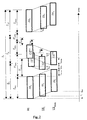
- Fig. 1 represents a schema of a half duplex communication system SYS which can, for example, be a Time Division Duplex (TDD) or a Half Duplex Frequency Division Duplex (HD FDD) communication system.
- the base station BS is equipped with communication means (not depicted in Fig. 1 ) for transmitting downlink sub-frames DL 1 and DL 2 to the user equipments UE i , and for receiving uplink sub-frames UL from them. It includes also means for defining frame idle periods reservation (FIPRM), the function of which is described below, and timing advance means (TAM) which implement a timing advance mechanism also explained below.
- FIPRM frame idle periods reservation
- TAM timing advance means
- a downlink sub-frame DL 1 is transmitted by the base station BS to the user equipment UE i .
- This transmission is followed by the transmission of an uplink sub-frame UL 1 , sent by this user equipment UE i to the base station BS.
- the notation UL is used for designating an uplink sub-frame independently from the user equipment UEi which transmits it.
- the transmission of the uplink sub-frame UL i is then followed by the transmission of another downlink sub-frame DL 2 .
- the succession of the downlink sub-frame DL 1 followed by the uplink sub-frame UL i followed by the downlink sub-frame DL 2 is called a frame.
- EP-A-1213855 discloses the idea of varying the length of guard periods in a TDD frame structure.
- Fig. 2 represents chronograms which depict the transmission of a frame of a half duplex communication system according to the state of the art.
- a frame includes a downlink sub-frame DL 1 with a predefined duration T DL1 , sub-frame which is followed by an uplink sub-frame UL with predefined duration T UL , sub-frame which is itself followed by another downlink sub-frame DL 2 with predefined duration T DL2 .
- these sub-frames do not necessarily have the same predefined duration, i.e. T DL1 may be different from T DL2 , T DL1 may be different from T UL and T DL2 may be different from T UL .
- an idle period is usually reserved, thanks to the FIPRM means, to avoid interference between two consecutive sub-frames and to avoid imposing any requirement on the half duplex base station BS and user equipments UE i to simultaneously receive and transmit consecutive sub-frames.
- an idle period IP DLUL is defined between the downlink sub-frame DL 1 and the uplink sub-frame UL
- another idle period IP ULDL is defined between the uplink sub-frame UL and the downlink sub-frame DL 2 .
- the effective transmission duration T E in which symbols embedded into the frame are transmitted is shorter than the total transmission duration of that frame T F .
- the frame idle period duration T I is the sum of idle period durations reserved in the frame.
- the effective transmission duration T E is the sum of the effective transmission duration T EDL1 of symbols embedded in the downlink sub-frame DL 1 , the effective transmission duration T EUL of symbols embedded in the uplink sub-frame UL and the effective transmission duration T EDL2 of symbols embedded in the downlink sub-frame DL 2 .
- IP DLUL or IP ULDL An idle period (IP DLUL or IP ULDL ) between the transmission of two consecutive sub-frames shall respect some requirements which define a required minimum idle duration of this idle period in order to allow the base station BS to manage correctly communications with each user equipment in communication with it. These requirements depend on the transmission scenario of sub-frames which is either a downlink sub-frame followed by an uplink sub-frame (DL/UL scenario) or an uplink sub-frame followed by a downlink sub-frame (UL/DL scenario).
- the base station BS cannot transmit to a user equipment UE i during a required minimum idle duration T DLUL , called in the following downlink/uplink required minimum idle duration, before a scheduled starting time for receiving by the base station BS the effective part of the uplink sub-frame UL i sent by the user equipment UE i .
- the downlink/uplink required minimum idle duration T DLUL during which the base station BS is not active for that user equipment UE i , has to be larger than twice the propagation time T prop between the base station BS and the user equipment UE i , plus the switching duration T RTUE for the user equipment UE i to switch from Receive to Transmit mode.
- T RTUE may not only include radio frequency device switching durations but also some additional margins to allow immediate processing of downlink control information in order to adapt the following uplink transmission.
- the maximum value 2xT prop-max is the round trip delay between the base station BS and the user equipment UE max located at the border of the cell covered by the base station BS
- the effective cell radius R is increased as the variance of the shadow fading is increased. Note that in some cases, the delay spread of the channel must be added.
- the base station BS cannot transmit to the user equipment UE i during the required minimum idle duration T ULDL , called in the following uplink/downlink required minimum idle duration, after a scheduled ending time for receiving by the base station BS the effective part of the uplink sub-frame UL i , to allow radio frequency switching (note: a half-duplex base station operating in unpaired spectrum is assumed here; a full duplex base station would not have radio frequency switching duration).
- the uplink/downlink required minimum idle duration T ULDL during which the base station is not active has to be larger than the switching duration T RTBS for the base station BS to switch from Receive to Transmit mode as depicted in Fig. 2 .
- T TRUE is the user equipment UE i 's switching duration which is, in the case of Fig. 2 , greater than T RTBS .
- T RTBS may not only include radio frequency device switching duration but also some additional margin to allow immediate processing of uplink control information in order to adapt the following downlink transmission.
- T ULDL max ⁇ T TRUE - 2. ⁇ T prop , T RTBS
- T prop increases, any impact of the user equipment UE i switching duration on T ULDL is reduced.
- the communication system needs to cope with a range of T prop values, including down to T prop ⁇ 0, and so the uplink/downlink required minimum idle duration T ULDL becomes set by the maximum of the user equipment UE i or base station BS switching durations. These switching durations are however expected to be negligible.
- T ULDL much shorter than T DLUL .
- T ULDL is usually close to 8 ⁇ s and T DLUL to 30 ⁇ s for a cell radius R equal to 5 km.
- the block structure of data can be advantageously taken into account for the dimensioning of the idle periods.
- OFDM Orthogonal Frequency Division Multiplexing
- SC-FDMA Single-Carrier Frequency Domain Multiple Access
- IFDMA Interleaved Frequency Division Multiple Access
- CDMA Code Division Multiple Access
- each idle period can be chosen as a multiple of a symbol duration (duration of symbols carried by either uplink sub-frames or by downlink sub-frames), the symbol being the block of samples (e.g., an OFDM symbol including the cyclic prefix, a SC-FDMA symbol including the cyclic prefix, etc.).
- uplink and downlink sub-frames are composed of a multiple number of symbols, the idle periods reservation allows adapting each idle period with respect to the cell range while keeping same transmission parameters (e.g. sampling frequency, FFT size, length of cyclic prefix, etc...) among sub-frames of a same link. This is advantageous because when idle periods are not needed during the communication of sub-frames, these idle periods can be replaced by symbols.
- block-wise transmission may also lie used for full duplex transmissions, a higher commonality between half duplex and full duplex is guaranteed.
- the required minimum idle durations given in (1) and (2) may not exactly match a multiple of a symbol duration. This leads to over-dimension the idle periods, i.e. to find, for each idle period which should be defined from its required minimum idle duration, the smallest idle period that is larger or equal to its required minimum idle duration and which is a multiple of a symbol duration.
- idle periods may be taken out of either a downlink sub-frame, or the uplink sub-frame or both as depicted more precisely in Figs. 3 and 4 .
- Figs. 3 and 4 represent examples of chronograms which depict frame idle periods reservations in the half duplex communication system SYS.
- the downlink/uplink idle duration IP DLUL can be reserved either in the preceding downlink sub-frame DL 1 as depicted in Fig. 3a , or the following uplink sub-frame as depicted in Fig. 3b or both as depicted in Fig. 3c .
- IP DLUL ⁇ T DLUL T SDL ⁇ 1 ⁇ ⁇ T SDL ⁇ 1 by taking into account a suitable dimensioning of the downlink/uplink required minimum idle duration T DLUL according to the above-mentioned requirements and the duration T SDL1 of symbols embedded in the downlink sub-frame DL 1 .
- ⁇ x ⁇ . defines the smallest integer larger than x.
- IP DLUL ⁇ T DLUL T SUL ⁇ ⁇ T SUL by taking into account a suitable dimensioning of the downlink/uplink idle period IP DLUL according to the above-mentioned requirements and the uplink symbol duration T SUL .
- the downlink/uplink required minimum duration T DLUL is equal to the summation of a downlink/uplink required duration T 1 DLUL taken out of the downlink sub-frame DL 1 and of a downlink/uplink required duration T 2 DLUL taken out of the uplink sub-frame UL.
- Symbols embedded in the downlink sub-frame DL 1 are thus transmitted only during the effective transmission duration T EDL1 and symbols embedded into the uplink sub-frame UL are only transmitted during the effective transmission duration T EUL as depicted in Fig. 3c .
- IP DLUL ⁇ T DLUL 1 T SDL ⁇ 1 ⁇ ⁇ T SDL ⁇ 1 + ⁇ T DLUL 2 T SUL ⁇ ⁇ T SUL by taking into account a suitable dimensioning of the downlink/uplink required minimum idle duration T DLUL according to the above-mentioned requirements and the downlink symbol duration T SDL1 for the part of the idle period in the downlink sub-frame DL 1 , and the uplink symbol duration T SUL for the part of the idle period in the uplink sub-frame.
- the uplink/downlink idle period IP ULDL can also be taken out of either the preceding uplink sub-frame (as depicted in Fig. 4 a) , or the following downlink sub-frame as depicted in Fig. 4 b) or both (as depicted in Fig. 4 c) .
- IP ULDL When the uplink/downlink idle period IP ULDL is taken out of the uplink sub-frame UL, symbols embedded in the uplink sub-frame UL are transmitted only during the effective transmission duration T EUL as depicted in Fig. 4a .
- IP ULDL ⁇ T ULDL T SDL ⁇ 2 ⁇ ⁇ T SDL ⁇ 2 by taking into account a suitable dimensioning of the uplink/downlink required minimum idle duration T ULDL according to the above-mentioned requirements and the downlink symbol duration T SDL2 .
- the uplink/downlink required minimum duration T ULDL is equal to the summation of a uplink/downlink required duration T 1 ULDL taken out of the uplink sub-frame UL and of a uplink/downlink required duration T 2 ULDL taken out of the downlink sub-frame DL 2 .
- Symbols embedded in the downlink sub-frame DL 2 are transmitted only during the effective transmission duration T EDL2 and symbols embedded in the uplink sub-frame UL are transmitted during the effective transmission T EUL as depicted in Fig. 4c .
- IP ULDL ⁇ T ULDL 1 T SUL ⁇ ⁇ T SUL + ⁇ T ULDL 2 T SDL ⁇ 2 ⁇ ⁇ T SDL ⁇ 2 by taking into account a suitable dimensioning of the uplink/downlink required minimum idle duration T ULDL according to the above-mentioned requirements and the uplink symbol duration T SUL for the part of the idle period in the uplink sub-frame UL, and the downlink symbol duration T SDL2 for the part of the idle period in the downlink sub-frame DL 2 .
- Idle periods are reserved in a frame using a combination of one configuration depicted in Fig. 3 with one configuration depicted in Fig. 4 .
- a configuration of Fig. 3 defines the effective duration of the uplink sub-frame UL as being equal to the total duration T UL , for example the configuration depicted in Fig.3a
- this effective transmission duration is reduced if a configuration of Fig. 4 defines that the idle period IP ULDL (or a part of it) is reserved in the end of the uplink sub-frame UL, for example configuration depicted in Fig. 4a .
- the effective parts of the uplink sub-frames UL sent by each user equipment UE i are all received at a same time, called the synchronization time of uplink sub-frames, in order to be synchronized at the base station BS.
- a user equipment UE i knowing only the starting time t i of the reception of the downlink sub-frame DL 1 , the effective downlink sub-frame duration T EDL1 and the duration of the idle period IP DLUL , is thus assumed to transmit the effective part of the uplink sub-frame UL at the time t i + T EDL 1 + T RTUE .
- T EDL1 the effective downlink sub-frame duration
- time t i being function of the distance between the base station BS and the user equipment UE i , transmitting the effective part of its uplink sub-frame UL at the time t i + T EDL 1 + T RTUE does not allow the synchronization of all uplink sub-frames at the base station at the synchronization time.
- the timing advance means TAM are used.
- Fig. 5 represents chronograms which illustrate the timing advance mechanism used by the base station BS for synchronizing uplink sub-frames according to the state of the art.
- a timing alignment mechanism consists in waiting for a certain amount of time after the end of the reception of the first downlink sub-frame DL 1 before starting the transmission of the effective part of the uplink sub-frame UL i by a user equipment UE i in order to align its reception starting time T STUL at the base station BS together with the reception starting time of the effective parts of the uplink sub-frames sent by other user equipments also performing this mechanism.
- This timing alignment mechanism is also called a timing advance mechanism.
- the user equipment UE i transmits its uplink sub-frame UL i at a time advanced by a timing advance value t Ai from a reference time defined by the following equation: t i + T EDL ⁇ 1 + IP DLUL
- the base station BS sends to each user equipment UE i the timing advance value t Ai from which a user equipment UE i defines the time at which it shall start the transmission of the effective part of the uplink sub-frame UL i .
- the timing advance mechanism requires thus the estimation at the base station BS of the propagation delay from the base station BS to each user equipment UE i in order to define such timing advance values t Ai .
- the timing advance values may be a fraction of the symbol duration.
- the effective transmission duration T E may be significantly reduced due to the over-dimensioning of idle periods IP DLUL and IP ULDL .
- the present invention aims at solving this problem by disclosing a method for communicating downlink and uplink sub-frames between a base station and at least one user equipment in a communication system, characterised in that the method comprises :
- the incremental value is greater than or equal to the switching duration for the base station to_switch from a receive mode to a transmit mode.
- the incremental value is different from the symbol duration.
- the incremental value is greater than or equal to the switching duration for the user equipment to switch from a transmit mode to a receive mode.
- Fig. 6 represents a chronogram which depicts an example of a frame of a half duplex communication system according to the present invention.
- the frame includes a first downlink sub-frame DL 1 with a predefined duration T DL1 , sub-frame which is followed by an uplink sub-frame UL with predefined duration T UL , sub-frame which is itself followed by another downlink sub-frame DL 2 with predefined duration T DL2 .
- these sub-frames do not necessarily have the same predefined duration, i.e. T DL1 may be different from T DL2 , T DL1 may be different from T UL and T DL2 may be different from T UL .
- the frame includes a single idle period IP which is at least equal to the summation of the downlink/uplink required minimum idle duration T DLUL and the uplink/downlink required minimum idle duration T ULDL .
- the single idle period IP is defined by over-dimensioning this summation as explained in the opening paragraph.
- the single idle period IP is taken out of either the end of the first downlink sub-frame DL 1 , or the beginning of the uplink sub-frame UL, or both.
- the frame does not include an idle period taken out of neither the end of the uplink sub-frame UL nor the beginning of the second downlink sub-frame DL 2 .
- Fig. 7 represents chronograms which illustrate the use of the timing advance mechanism for synchronizing the effective parts of uplink sub-frames according to the present invention.
- References of elements depicted in Fig. 5 and 6 which are identical to references of elements depicted in Fig. 7 are assigned to the same elements.
- the synchronization time T' STUL is advanced by an incremental timing advance value ⁇ t A .
- the new synchronisation time T" STUL is thus equal to t 0 + T EDL 1 + IP - ⁇ t A .
- the incremental timing advance value ⁇ t A shall be greater than or equal to the uplink/downlink required minimum idle duration T ULDL in order to allow switchings. Furthermore, the duration IP- ⁇ t A between the end of the transmission of the effective part of the first downlink sub-frame DL 1 and the beginning of the reception of the effective part of the uplink sub-frame UL shall be greater than or equal to the downlink/uplink required minimum idle duration T DLUL . Thus, the incremental timing advance value ⁇ t A shall be lower than or equal to the duration IP-T DLUL .
- the incremental timing advance value ⁇ t A is added to each timing advance value t Ai to be used to perform the timing advance mechanism at each user equipment UE i .
- the present invention may improve the spectral efficiency by reducing the frame idle period duration T 1 because over-dimensioning the sum of T ULDL and T DLUL may be more efficient than over-dimensioning these durations separately.
- the downlink/uplink idle period IP DLUL would be equal to 70 ⁇ s
- the uplink/downlink idle period IP ULDL would be equal to 60 ⁇ s
- the idle period IP would be equal to 70 ⁇ s.
- the frame idle period duration is reduced.
- the present invention may also improve the coverage of the base station BS when IP- ⁇ t A is larger than the downlink/uplink idle period IP DLUL , which allows the base station BS to communicate with user equipments located farther than the effective cell radius R.
- the downlink/uplink idle period IP DLUL would be equal to 47 ⁇ s
- the uplink/downlink idle period IP ULDL would be equal to 45 ⁇ s
- the idle period IP would be equal to 94 ⁇ s.
- ⁇ t A equal to T ULDL
- the addition of the timing advance value t Ai and the incremental timing advance value ⁇ t A is performed and the result is transmitted by the base station to each user equipment UE i .
- the incremental timing advance value ⁇ t A is transmitted by the base station to each of said user equipments.
- the incremental timing advance value ⁇ t A is stored by each of said user equipments.
- the idle period IP is a multiple of a symbol duration which is either T SDL1 or T SUL .
- the idle period IP is a sum of a multiple of the duration T SDL1 of symbols embedded into the first downlink sub-frame and a multiple of the duration T SUL of symbols embedded into the uplink sub-frame.
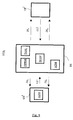
- Fig. 8 represents a schema of a half duplex communication system SYS 1 according to the present invention.
- the communication system SYS 1 is, for example, a Time Division Duplex (TDD) or a Half Duplex Frequency Division Duplex (HD FDD) communication system.
- the communication system SYS 1 allows half-duplex communications between a communication apparatus BS, which is for example a base station and at least one user equipments UE i and/or at least one user equipment UE j which are both, for example mobile phones or fixed wireless terminals.
- a communication apparatus BS which is for example a base station and at least one user equipments UE i and/or at least one user equipment UE j which are both, for example mobile phones or fixed wireless terminals.
- the communication apparatus BS is involved in the half duplex communication system SYS 1 for the communication of downlink sub-frames DL 1 and DL 2 and uplink sub-frames UL with the user equipments UE i (or UE j ).
- a first downlink sub-frame DL 1 is transmitted by the communication apparatus BS to the user equipments UE i (or UE j ), followed by the uplink sub-frame UL transmitted from the user equipments UE i (or UE j ) to the communication apparatus BS.
- the uplink sub-frame UL is then itself followed by the second downlink sub-frame DL 2 transmitted to the user equipments UE i (or UE j ), the transmission of the effective part of the first downlink sub-frame DL 1 being separated from the reception of the effective part of the uplink sub-frame UL by at least a downlink/uplink required minimum idle duration T DLUL , the reception of the effective part of said uplink sub-frame UL is separated from the transmission of the effective part of said second downlink sub-frame DL 2 by at least an uplink/downlink required minimum idle duration T ULDL .
- said communication apparatus BS includes :
- the communication apparatus BS includes means ADM for adding said incremental timing advance value ⁇ t A to the timing advance value t Ai of one of user equipments UE i .
- the communication apparatus BS includes means for transmitting said incremental timing advance value ⁇ t A .
- the user equipment UE j includes means for adding the incremental timing advance value ⁇ t A to the timing advance value t Ai .
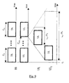
- Fig. 9 represents chronograms which illustrate the use of the timing advance mechanism for synchronizing uplink sub-frames in a full duplex communication system according to the present invention.
- downlink and uplink sub-frames are transmitted simultaneously. Moreover, no idle periods are reserved in the frame which is depicted here as a set of downlink sub-frames DL and a set of uplink sub-frames UL having the same duration T DL .
- the beginning of the uplink sub-frames sent by each user equipment UE i are received at a same time instant thanks to the timing advance mechanism.
- the incremental timing advance value ⁇ t A is added to each timing advance value t Ai to be used to perform the timing advance mechanism at each user equipment.
Claims (4)
- Verfahren zum Kommunizieren von Abwärtsstrecken- und Aufwärtsstrecken-Subframes zwischen einer Basisstation und wenigstens einem Anwendergerät in einem Kommunikationssystem,
wobei das Verfahren folgendes aufweist:- einen Abwärtsstrecken-Sendeschritt, in dessen Verlauf ein erster Abwärtsstrecken-Subframe (DL1) durch die Basisstation zu dem Anwendergerät gesendet wird, wobei in dem ersten Abwärtsstrecken-Subframe eingebettete Symbole eine erste Dauer (TSDL1) haben,- einen Abwärtsstrecken-Empfangsschritt, in dessen Verlauf der von der Basisstation gesendete erste Abwärtsstrecken-Subframe (DL1) durch das Anwendergerät empfangen wird,- einen Zeitfortschrittswert-Sendeschritt, in dessen Verlauf ein Zeitfortschrittswert (tAi) von der Basisstation zu dem Anwendergerät gesendet wird, wobei der Zeitfortschrittswert (tAi) zum Bestimmen einer Startzeit eines Aufwärtsstrecken-Sendens durch das Anwendergerät vorbereitet ist,- einen Zeitfortschrittswert-Empfangsschritt, in dessen Verlauf der von der Basisstation gesendete Zeitfortschrittswert (tAi) durch das Anwendergerät empfangen wird,- einen Bestimmungsschritt, in dessen Verlauf die Zeit, um einen Aufwärtsstrecken-Subframe (UL1, UL2) zu senden, bei dem Anwendergerät auf der Basis des in dem Zeitfortschrittswert-Empfangsschritt empfangenen Zeitfortschrittswerts (tAi) und eines vor dem Bestimmungsschritt vorbereiteten inkrementalen Werts (ΔtA) bestimmt wird,- einen Aufwärtsstrecken-Sendeschritt, in dessen Verlauf der Aufwärtsstrecken-Subframe (UL1, UL2) zu der in dem Bestimmungsschritt bestimmten Zeit von dem Anwendergerät zu der Basisstation gesendet wird, wobei in dem Aufwärtsstrecken-Subframe eingebettete Symbole en zweite Dauer (TSUL) haben,- einen Aufwärtsstrecken-Empfangsschritt, in dessen Verlauf der in dem Aufwärtsstrecken-Sendeschritt gesendete Aufwärtsstrecken-Subframe (UL1, UL2) empfangen wird, wobei der Aufwärtsstrecken-Subframe eine erste Zeitperiode nach dem Ende des Sendens des ersten Abwärtsstrecken-Subframes empfangen wird,- einen Abwärtsstrecken-Sendeschritt, in dessen Verlauf ein zweiter Abwärtsstrecken-Subframe (DL2) durch die Basisstation zu dem Anwendergerät gesendet wird, wobei der zweite Abwärtsstrecken-Subframe eine zweite Zeitperiode nach dem Ende des Empfangs des Aufwärtsstrecken-Subframes gesendet wird und die Summe der ersten und der zweiten Zeitperiode ein Vielfaches der ersten oder der zweiten Symboldauer ist oder die Summe der ersten und der zweiten Zeitperiode ein Summe eines Vielfachen der ersten Symboldauer und eines Vielfachen der zweiten Symboldauer ist. - Verfahren Kommunizieren von Abwärtsstrecken- und Aufwärtsstrecken-Subframes nach Anspruch 1, wobei der inkrementale Wert (ΔtA) größer als die Umschaltdauer für die Basisstation, um von einem Empfangsmode zu einem Sendemode umzuschalten, oder gleich dieser ist.
- Verfahren Kommunizieren von Abwärtsstrecken- und Aufwärtsstrecken-Subframes nach Anspruch 1, wobei der inkrementale Wert (ΔtA) unterschiedlich von der Symboldauer ist.
- Verfahren Kommunizieren von Abwärtsstrecken- und Aufwärtsstrecken-Subframes nach Anspruch 1, wobei der inkrementale Wert (ΔtA) größer als die Umschaltdauer für das Anwendergerät, um von einem Sendemode zu einem Empfangsmode umzuschalten, oder gleich dieser ist.
Priority Applications (1)
| Application Number | Priority Date | Filing Date | Title |
|---|---|---|---|
| EP09163479.0A EP2134006B1 (de) | 2005-10-26 | 2006-01-13 | Verfahren zur Übermittlung von Abwärts- und Aufwärtsstrecken-Unterrahmen in einem Halbduplexkommunikationssystem |
Applications Claiming Priority (3)
| Application Number | Priority Date | Filing Date | Title |
|---|---|---|---|
| EP05292273 | 2005-10-26 | ||
| EP06290095A EP1821429A3 (de) | 2005-10-26 | 2006-01-13 | Verfahren und Vorrichtung zum Übertragen von Unterrahmen in Ab- und Aufwärtsrichtung in einem halb-duplex Kommunikationssystem |
| EP09163479.0A EP2134006B1 (de) | 2005-10-26 | 2006-01-13 | Verfahren zur Übermittlung von Abwärts- und Aufwärtsstrecken-Unterrahmen in einem Halbduplexkommunikationssystem |
Related Parent Applications (1)
| Application Number | Title | Priority Date | Filing Date |
|---|---|---|---|
| EP06290095A Division EP1821429A3 (de) | 2005-10-26 | 2006-01-13 | Verfahren und Vorrichtung zum Übertragen von Unterrahmen in Ab- und Aufwärtsrichtung in einem halb-duplex Kommunikationssystem |
Publications (2)
| Publication Number | Publication Date |
|---|---|
| EP2134006A1 EP2134006A1 (de) | 2009-12-16 |
| EP2134006B1 true EP2134006B1 (de) | 2014-10-08 |
Family
ID=38050035
Family Applications (2)
| Application Number | Title | Priority Date | Filing Date |
|---|---|---|---|
| EP09163479.0A Active EP2134006B1 (de) | 2005-10-26 | 2006-01-13 | Verfahren zur Übermittlung von Abwärts- und Aufwärtsstrecken-Unterrahmen in einem Halbduplexkommunikationssystem |
| EP06290095A Ceased EP1821429A3 (de) | 2005-10-26 | 2006-01-13 | Verfahren und Vorrichtung zum Übertragen von Unterrahmen in Ab- und Aufwärtsrichtung in einem halb-duplex Kommunikationssystem |
Family Applications After (1)
| Application Number | Title | Priority Date | Filing Date |
|---|---|---|---|
| EP06290095A Ceased EP1821429A3 (de) | 2005-10-26 | 2006-01-13 | Verfahren und Vorrichtung zum Übertragen von Unterrahmen in Ab- und Aufwärtsrichtung in einem halb-duplex Kommunikationssystem |
Country Status (5)
| Country | Link |
|---|---|
| US (1) | US8068444B2 (de) |
| EP (2) | EP2134006B1 (de) |
| JP (2) | JP4852615B2 (de) |
| KR (2) | KR20100095482A (de) |
| CN (2) | CN101305531A (de) |
Families Citing this family (34)
| Publication number | Priority date | Publication date | Assignee | Title |
|---|---|---|---|---|
| US8462676B2 (en) | 2006-10-17 | 2013-06-11 | Intel Corporation | Frame structure for support of large delay spread deployment scenarios |
| CN101682397B (zh) * | 2007-01-15 | 2013-05-29 | 艾利森电话股份有限公司 | 用于在无线接入tdd系统中的增强的性能的方法和设备 |
| US8331286B2 (en) * | 2007-08-03 | 2012-12-11 | Qualcomm Incorporated | Method and apparatus for efficient selection and acquisition of systems utilizing OFDM or SC-FDM |
| US8031693B2 (en) * | 2007-11-20 | 2011-10-04 | Research In Motion Limited | System and method for timing synchronization |
| CN101483476B (zh) * | 2008-01-07 | 2012-06-27 | 华为技术有限公司 | 一种区分上下行子帧的休眠方法 |
| KR100904533B1 (ko) * | 2008-01-11 | 2009-06-25 | 엘지전자 주식회사 | 전송 타이밍 조절 방법, 연속적인 패킷 전송 방법 및 이동통신 단말 |
| ATE486478T1 (de) * | 2008-02-15 | 2010-11-15 | Mitsubishi Electric Corp | Verfahren und vorrichtung zur entscheidung, ob eine basisstation ein endgerät nicht nutzen kann |
| WO2009102181A1 (en) * | 2008-02-17 | 2009-08-20 | Lg Electronics Inc. | Method of communication using frame |
| EP2247132A4 (de) * | 2008-02-19 | 2014-04-09 | Ntt Docomo Inc | Mobiles kommunikationssystem, basisstationsgerät, benutzerausrüstung und verfahren |
| DE602008004306D1 (de) * | 2008-02-20 | 2011-02-17 | Mitsubishi Electric Corp | Verfahren und Vorrichtung zur Bestimmung, welche in einem Downlink-Zeitschlitz übertragenen Signale durch ein Halbduplex-Endgerät ausgewählt werden sollen |
| US8542617B2 (en) | 2008-06-02 | 2013-09-24 | Apple Inc. | Adaptive operational full-duplex and half-duplex FDD modes in wireless networks |
| BRPI0823373B1 (pt) * | 2008-12-23 | 2021-03-09 | Telecom Italia S.P.A | método e sistema de alocar recursos de comunicação de enlace descendente e enlace ascendente, e, meio legível por computador |
| US9397876B2 (en) * | 2009-02-20 | 2016-07-19 | Broadcom Corporation | Synchronization and frame structure determination of a base station |
| US9137764B2 (en) | 2009-03-17 | 2015-09-15 | Htc Corporation | Method of managing timing alignment functionality for multiple component carriers and related communication device |
| US8837457B2 (en) * | 2009-08-21 | 2014-09-16 | Electronics And Telecommunications Research Institute | Method and apparatus for adjusting signal transmission starting point of terminal in wireless network |
| US20110243111A1 (en) * | 2010-03-31 | 2011-10-06 | Niklas Andgart | Timing of Uplink Transmissions in a Multi-Carrier Communication System |
| US9414336B2 (en) | 2010-05-12 | 2016-08-09 | Blackberry Limited | System and method for defining a burst period |
| US8989025B2 (en) * | 2010-11-12 | 2015-03-24 | Telefonaktiebolaget L M Ericsson (Publ) | UE timing adjustment in a multi-RAT, carrier aggregation community system |
| US10405306B2 (en) | 2011-09-29 | 2019-09-03 | Qualcomm Incorporated | Half-duplex operation for low cost wireless devices |
| US9060351B2 (en) * | 2011-12-23 | 2015-06-16 | Broadcom Corporation | Decoupled downlink and uplink |
| US8972614B2 (en) | 2011-12-26 | 2015-03-03 | Apple Inc. | Half-duplex SATA link with controlled idle gap insertion |
| US9763239B2 (en) | 2012-01-29 | 2017-09-12 | Lg Electronics Inc. | Data transmission method and apparatus for half-duplex devices |
| EP2813025B1 (de) * | 2012-02-07 | 2016-10-26 | Telefonaktiebolaget LM Ericsson (publ) | Verfahren und einrichtung zur sendtaktregelung |
| CN103634086B (zh) * | 2012-08-28 | 2018-12-21 | 中兴通讯股份有限公司 | 调整上下行时间分配的方法、系统、局端设备及cpe |
| EP3103301A1 (de) * | 2014-02-03 | 2016-12-14 | Telefonaktiebolaget LM Ericsson (publ) | Adaptive uplink-downlink-schaltzeit für halbduplexbetrieb |
| US10693574B2 (en) * | 2015-07-02 | 2020-06-23 | Qualcomm Incorporated | Method and apparatus for efficient data transmissions in half-duplex communication systems with large propagation delays |
| US9814056B2 (en) | 2015-08-24 | 2017-11-07 | Qualcomm Incorporated | Methods and apparatus for interference management of wireless links with overriding link priority |
| CN108604961B (zh) * | 2015-12-15 | 2020-12-22 | 马维尔国际有限公司 | 用于在无线通信网络中通信的方法和通信设备 |
| US10405334B2 (en) * | 2015-12-18 | 2019-09-03 | Qualcomm Incorporated | Techniques for switching between downlink and uplink communications |
| GB2554649A (en) * | 2016-09-30 | 2018-04-11 | Tcl Communication Ltd | Systems and methods for frequency division duplex communication |
| JP6822724B2 (ja) * | 2016-11-04 | 2021-01-27 | ホアウェイ・テクノロジーズ・カンパニー・リミテッド | 測位情報伝送方法、基地局、装置、測位サーバ、コンピュータ可読記憶媒体およびプログラム |
| KR102354587B1 (ko) * | 2017-09-08 | 2022-01-24 | 삼성전자 주식회사 | 무선 통신 시스템에서 상향링크 전송을 위한 방법 및 장치 |
| CN108156595B (zh) * | 2017-12-05 | 2020-07-03 | 南京邮电大学 | 一种机器通信中基于定时提前命令的前导资源分配方法 |
| CN112188609B (zh) * | 2019-07-04 | 2021-11-19 | 华为技术有限公司 | 确定定时提前ta参考时刻的方法和装置 |
Family Cites Families (9)
| Publication number | Priority date | Publication date | Assignee | Title |
|---|---|---|---|---|
| JP3881770B2 (ja) * | 1998-03-10 | 2007-02-14 | 松下電器産業株式会社 | 移動局装置および通信方法 |
| EP1206150A1 (de) * | 2000-11-13 | 2002-05-15 | Lucent Technologies Inc. | Erweiterte Zellenreichweite in einem TDD UTRAN |
| CN1214553C (zh) * | 2000-11-17 | 2005-08-10 | 三星电子株式会社 | 在窄带时分双工码分多址移动通信系统中测量传播延迟的设备和方法 |
| EP1213855A1 (de) * | 2000-12-08 | 2002-06-12 | Lucent Technologies Inc. | Rahmenstruktur für TDD-Telekommunikationssystemen |
| CN100531458C (zh) * | 2002-05-13 | 2009-08-19 | 三星电子株式会社 | 执行无线接入技术间测量的方法 |
| KR100455157B1 (ko) * | 2002-08-29 | 2004-11-06 | 엘지전자 주식회사 | 이동 통신 단말기의 고주파처리칩의 모드 전환 방법 |
| JP4291019B2 (ja) * | 2003-03-13 | 2009-07-08 | 株式会社日立国際電気 | Ofdm方式の伝送装置 |
| JP2005130256A (ja) * | 2003-10-24 | 2005-05-19 | Ntt Docomo Inc | 移動局装置、基地局装置、無線通信システムおよび無線通信方法 |
| JP2005269061A (ja) * | 2004-03-17 | 2005-09-29 | Nara Institute Of Science & Technology | 受信タイミングが制御される無線通信システム |
-
2006
- 2006-01-13 EP EP09163479.0A patent/EP2134006B1/de active Active
- 2006-01-13 EP EP06290095A patent/EP1821429A3/de not_active Ceased
- 2006-09-28 KR KR1020107018028A patent/KR20100095482A/ko active IP Right Grant
- 2006-09-28 US US12/091,139 patent/US8068444B2/en active Active
- 2006-09-28 KR KR1020087010367A patent/KR101254268B1/ko active IP Right Grant
- 2006-09-28 CN CNA2006800400258A patent/CN101305531A/zh active Pending
- 2006-09-28 JP JP2008536958A patent/JP4852615B2/ja active Active
- 2006-09-28 CN CN201010167185A patent/CN101834659A/zh active Pending
-
2010
- 2010-08-13 JP JP2010181317A patent/JP2011019258A/ja active Pending
Also Published As
| Publication number | Publication date |
|---|---|
| EP2134006A1 (de) | 2009-12-16 |
| CN101834659A (zh) | 2010-09-15 |
| KR20100095482A (ko) | 2010-08-30 |
| US20080232278A1 (en) | 2008-09-25 |
| US8068444B2 (en) | 2011-11-29 |
| KR101254268B1 (ko) | 2013-04-12 |
| CN101305531A (zh) | 2008-11-12 |
| JP4852615B2 (ja) | 2012-01-11 |
| KR20080069587A (ko) | 2008-07-28 |
| JP2011019258A (ja) | 2011-01-27 |
| EP1821429A2 (de) | 2007-08-22 |
| JP2009514280A (ja) | 2009-04-02 |
| EP1821429A3 (de) | 2007-09-05 |
Similar Documents
| Publication | Publication Date | Title |
|---|---|---|
| EP2134006B1 (de) | Verfahren zur Übermittlung von Abwärts- und Aufwärtsstrecken-Unterrahmen in einem Halbduplexkommunikationssystem | |
| EP1952560B1 (de) | Technik zum durchführen einer direktzugriffsprozedur über eine funkschnittstelle | |
| EP2169850B1 (de) | Verfahren zur nachrichtenübertragung in tdd anordnungen und anpassende rahmenstruktur dafür | |
| US9107077B2 (en) | Method and system for time synchronization of WiMAX and LTE-TDD networks | |
| US8199706B2 (en) | Random access design for high doppler in wireless networks | |
| EP1946575B1 (de) | Zellulares kommunikationssystem und verfahren für koexistenz unähnlicher systeme | |
| CN114760020A (zh) | 无线通信系统中基于短传输时间间隔的通信方法和装置 | |
| KR101261037B1 (ko) | 통신 방법 및 장치 | |
| KR20120099623A (ko) | 전기통신망에서 방법 및 배열 | |
| CN101425845A (zh) | 一种时分双工系统的传输方法和装置 | |
| WO2007048478A1 (en) | Method and apparatus for communicating downlink and uplink sub-frames in a half duplex communication system | |
| CN101374011B (zh) | 实现两种不同通信系统间临频共存的方法及物理层帧结构 | |
| CN102273284A (zh) | 用于促进上行链路同步的方法和装置 | |
| WO2006110774A2 (en) | Method and system for performing uplink synchronization | |
| WO2008115105A1 (en) | A method and a device for reduced interference in a cellular access system. | |
| KR20100132464A (ko) | 전송 타이밍 조절 방법 및 이를 위한 장치 | |
| US7548554B2 (en) | Methods for controlling transmission of high-speed data traffic in IPDLs | |
| US8130743B2 (en) | Cellular radiotelephone signal permitting synchronization of a supplementary channel by means of a principal channel and corresponding method, terminal and base station | |
| CN108476492B (zh) | 无线通信方法和设备 | |
| CN102318415A (zh) | 促进td-scdma多载波系统中的上行链路同步 |
Legal Events
| Date | Code | Title | Description |
|---|---|---|---|
| PUAI | Public reference made under article 153(3) epc to a published international application that has entered the european phase |
Free format text: ORIGINAL CODE: 0009012 |
|
| AC | Divisional application: reference to earlier application |
Ref document number: 1821429 Country of ref document: EP Kind code of ref document: P |
|
| AK | Designated contracting states |
Kind code of ref document: A1 Designated state(s): AT BE BG CH CY CZ DE DK EE ES FI FR GB GR HU IE IS IT LI LT LU LV MC NL PL PT RO SE SI SK TR |
|
| 17P | Request for examination filed |
Effective date: 20100223 |
|
| 17Q | First examination report despatched |
Effective date: 20110202 |
|
| GRAP | Despatch of communication of intention to grant a patent |
Free format text: ORIGINAL CODE: EPIDOSNIGR1 |
|
| INTG | Intention to grant announced |
Effective date: 20140328 |
|
| GRAS | Grant fee paid |
Free format text: ORIGINAL CODE: EPIDOSNIGR3 |
|
| GRAA | (expected) grant |
Free format text: ORIGINAL CODE: 0009210 |
|
| AC | Divisional application: reference to earlier application |
Ref document number: 1821429 Country of ref document: EP Kind code of ref document: P |
|
| AK | Designated contracting states |
Kind code of ref document: B1 Designated state(s): AT BE BG CH CY CZ DE DK EE ES FI FR GB GR HU IE IS IT LI LT LU LV MC NL PL PT RO SE SI SK TR |
|
| REG | Reference to a national code |
Ref country code: GB Ref legal event code: FG4D |
|
| REG | Reference to a national code |
Ref country code: AT Ref legal event code: REF Ref document number: 691099 Country of ref document: AT Kind code of ref document: T Effective date: 20141015 Ref country code: CH Ref legal event code: EP |
|
| REG | Reference to a national code |
Ref country code: IE Ref legal event code: FG4D |
|
| REG | Reference to a national code |
Ref country code: DE Ref legal event code: R096 Ref document number: 602006043326 Country of ref document: DE Effective date: 20141120 |
|
| REG | Reference to a national code |
Ref country code: NL Ref legal event code: VDEP Effective date: 20141008 |
|
| REG | Reference to a national code |
Ref country code: AT Ref legal event code: MK05 Ref document number: 691099 Country of ref document: AT Kind code of ref document: T Effective date: 20141008 |
|
| REG | Reference to a national code |
Ref country code: LT Ref legal event code: MG4D |
|
| PG25 | Lapsed in a contracting state [announced via postgrant information from national office to epo] |
Ref country code: NL Free format text: LAPSE BECAUSE OF FAILURE TO SUBMIT A TRANSLATION OF THE DESCRIPTION OR TO PAY THE FEE WITHIN THE PRESCRIBED TIME-LIMIT Effective date: 20141008 |
|
| PG25 | Lapsed in a contracting state [announced via postgrant information from national office to epo] |
Ref country code: PT Free format text: LAPSE BECAUSE OF FAILURE TO SUBMIT A TRANSLATION OF THE DESCRIPTION OR TO PAY THE FEE WITHIN THE PRESCRIBED TIME-LIMIT Effective date: 20150209 Ref country code: FI Free format text: LAPSE BECAUSE OF FAILURE TO SUBMIT A TRANSLATION OF THE DESCRIPTION OR TO PAY THE FEE WITHIN THE PRESCRIBED TIME-LIMIT Effective date: 20141008 Ref country code: LT Free format text: LAPSE BECAUSE OF FAILURE TO SUBMIT A TRANSLATION OF THE DESCRIPTION OR TO PAY THE FEE WITHIN THE PRESCRIBED TIME-LIMIT Effective date: 20141008 Ref country code: IS Free format text: LAPSE BECAUSE OF FAILURE TO SUBMIT A TRANSLATION OF THE DESCRIPTION OR TO PAY THE FEE WITHIN THE PRESCRIBED TIME-LIMIT Effective date: 20150208 Ref country code: ES Free format text: LAPSE BECAUSE OF FAILURE TO SUBMIT A TRANSLATION OF THE DESCRIPTION OR TO PAY THE FEE WITHIN THE PRESCRIBED TIME-LIMIT Effective date: 20141008 |
|
| PG25 | Lapsed in a contracting state [announced via postgrant information from national office to epo] |
Ref country code: PL Free format text: LAPSE BECAUSE OF FAILURE TO SUBMIT A TRANSLATION OF THE DESCRIPTION OR TO PAY THE FEE WITHIN THE PRESCRIBED TIME-LIMIT Effective date: 20141008 Ref country code: SE Free format text: LAPSE BECAUSE OF FAILURE TO SUBMIT A TRANSLATION OF THE DESCRIPTION OR TO PAY THE FEE WITHIN THE PRESCRIBED TIME-LIMIT Effective date: 20141008 Ref country code: AT Free format text: LAPSE BECAUSE OF FAILURE TO SUBMIT A TRANSLATION OF THE DESCRIPTION OR TO PAY THE FEE WITHIN THE PRESCRIBED TIME-LIMIT Effective date: 20141008 Ref country code: GR Free format text: LAPSE BECAUSE OF FAILURE TO SUBMIT A TRANSLATION OF THE DESCRIPTION OR TO PAY THE FEE WITHIN THE PRESCRIBED TIME-LIMIT Effective date: 20150109 Ref country code: CY Free format text: LAPSE BECAUSE OF FAILURE TO SUBMIT A TRANSLATION OF THE DESCRIPTION OR TO PAY THE FEE WITHIN THE PRESCRIBED TIME-LIMIT Effective date: 20141008 Ref country code: LV Free format text: LAPSE BECAUSE OF FAILURE TO SUBMIT A TRANSLATION OF THE DESCRIPTION OR TO PAY THE FEE WITHIN THE PRESCRIBED TIME-LIMIT Effective date: 20141008 |
|
| PG25 | Lapsed in a contracting state [announced via postgrant information from national office to epo] |
Ref country code: BE Free format text: LAPSE BECAUSE OF NON-PAYMENT OF DUE FEES Effective date: 20150131 |
|
| REG | Reference to a national code |
Ref country code: DE Ref legal event code: R097 Ref document number: 602006043326 Country of ref document: DE |
|
| PG25 | Lapsed in a contracting state [announced via postgrant information from national office to epo] |
Ref country code: EE Free format text: LAPSE BECAUSE OF FAILURE TO SUBMIT A TRANSLATION OF THE DESCRIPTION OR TO PAY THE FEE WITHIN THE PRESCRIBED TIME-LIMIT Effective date: 20141008 Ref country code: DK Free format text: LAPSE BECAUSE OF FAILURE TO SUBMIT A TRANSLATION OF THE DESCRIPTION OR TO PAY THE FEE WITHIN THE PRESCRIBED TIME-LIMIT Effective date: 20141008 Ref country code: CZ Free format text: LAPSE BECAUSE OF FAILURE TO SUBMIT A TRANSLATION OF THE DESCRIPTION OR TO PAY THE FEE WITHIN THE PRESCRIBED TIME-LIMIT Effective date: 20141008 Ref country code: SK Free format text: LAPSE BECAUSE OF FAILURE TO SUBMIT A TRANSLATION OF THE DESCRIPTION OR TO PAY THE FEE WITHIN THE PRESCRIBED TIME-LIMIT Effective date: 20141008 Ref country code: RO Free format text: LAPSE BECAUSE OF FAILURE TO SUBMIT A TRANSLATION OF THE DESCRIPTION OR TO PAY THE FEE WITHIN THE PRESCRIBED TIME-LIMIT Effective date: 20141008 |
|
| PLBE | No opposition filed within time limit |
Free format text: ORIGINAL CODE: 0009261 |
|
| STAA | Information on the status of an ep patent application or granted ep patent |
Free format text: STATUS: NO OPPOSITION FILED WITHIN TIME LIMIT |
|
| REG | Reference to a national code |
Ref country code: CH Ref legal event code: PL |
|
| PG25 | Lapsed in a contracting state [announced via postgrant information from national office to epo] |
Ref country code: LU Free format text: LAPSE BECAUSE OF FAILURE TO SUBMIT A TRANSLATION OF THE DESCRIPTION OR TO PAY THE FEE WITHIN THE PRESCRIBED TIME-LIMIT Effective date: 20150113 Ref country code: IT Free format text: LAPSE BECAUSE OF FAILURE TO SUBMIT A TRANSLATION OF THE DESCRIPTION OR TO PAY THE FEE WITHIN THE PRESCRIBED TIME-LIMIT Effective date: 20141008 |
|
| 26N | No opposition filed |
Effective date: 20150709 |
|
| PG25 | Lapsed in a contracting state [announced via postgrant information from national office to epo] |
Ref country code: MC Free format text: LAPSE BECAUSE OF FAILURE TO SUBMIT A TRANSLATION OF THE DESCRIPTION OR TO PAY THE FEE WITHIN THE PRESCRIBED TIME-LIMIT Effective date: 20141008 |
|
| PG25 | Lapsed in a contracting state [announced via postgrant information from national office to epo] |
Ref country code: CH Free format text: LAPSE BECAUSE OF NON-PAYMENT OF DUE FEES Effective date: 20150131 Ref country code: LI Free format text: LAPSE BECAUSE OF NON-PAYMENT OF DUE FEES Effective date: 20150131 |
|
| REG | Reference to a national code |
Ref country code: IE Ref legal event code: MM4A |
|
| REG | Reference to a national code |
Ref country code: FR Ref legal event code: PLFP Year of fee payment: 11 |
|
| PG25 | Lapsed in a contracting state [announced via postgrant information from national office to epo] |
Ref country code: IE Free format text: LAPSE BECAUSE OF NON-PAYMENT OF DUE FEES Effective date: 20150113 |
|
| PG25 | Lapsed in a contracting state [announced via postgrant information from national office to epo] |
Ref country code: SI Free format text: LAPSE BECAUSE OF FAILURE TO SUBMIT A TRANSLATION OF THE DESCRIPTION OR TO PAY THE FEE WITHIN THE PRESCRIBED TIME-LIMIT Effective date: 20141008 |
|
| REG | Reference to a national code |
Ref country code: FR Ref legal event code: PLFP Year of fee payment: 12 |
|
| PG25 | Lapsed in a contracting state [announced via postgrant information from national office to epo] |
Ref country code: HU Free format text: LAPSE BECAUSE OF FAILURE TO SUBMIT A TRANSLATION OF THE DESCRIPTION OR TO PAY THE FEE WITHIN THE PRESCRIBED TIME-LIMIT; INVALID AB INITIO Effective date: 20060113 Ref country code: BG Free format text: LAPSE BECAUSE OF FAILURE TO SUBMIT A TRANSLATION OF THE DESCRIPTION OR TO PAY THE FEE WITHIN THE PRESCRIBED TIME-LIMIT Effective date: 20141008 |
|
| PG25 | Lapsed in a contracting state [announced via postgrant information from national office to epo] |
Ref country code: TR Free format text: LAPSE BECAUSE OF FAILURE TO SUBMIT A TRANSLATION OF THE DESCRIPTION OR TO PAY THE FEE WITHIN THE PRESCRIBED TIME-LIMIT Effective date: 20141008 |
|
| REG | Reference to a national code |
Ref country code: FR Ref legal event code: PLFP Year of fee payment: 13 |
|
| PGFP | Annual fee paid to national office [announced via postgrant information from national office to epo] |
Ref country code: FR Payment date: 20230124 Year of fee payment: 18 |
|
| P01 | Opt-out of the competence of the unified patent court (upc) registered |
Effective date: 20230512 |
|
| REG | Reference to a national code |
Ref country code: DE Ref legal event code: R082 Ref document number: 602006043326 Country of ref document: DE Representative=s name: PUSCHMANN BORCHERT KAISER KLETTNER PATENTANWAE, DE |
|
| PGFP | Annual fee paid to national office [announced via postgrant information from national office to epo] |
Ref country code: DE Payment date: 20240119 Year of fee payment: 19 Ref country code: GB Payment date: 20240123 Year of fee payment: 19 |