EP2133934A1 - Secondary battery - Google Patents
Secondary battery Download PDFInfo
- Publication number
- EP2133934A1 EP2133934A1 EP09251517A EP09251517A EP2133934A1 EP 2133934 A1 EP2133934 A1 EP 2133934A1 EP 09251517 A EP09251517 A EP 09251517A EP 09251517 A EP09251517 A EP 09251517A EP 2133934 A1 EP2133934 A1 EP 2133934A1
- Authority
- EP
- European Patent Office
- Prior art keywords
- secondary battery
- rupture
- electrode assembly
- battery according
- lithium secondary
- Prior art date
- Legal status (The legal status is an assumption and is not a legal conclusion. Google has not performed a legal analysis and makes no representation as to the accuracy of the status listed.)
- Granted
Links
Images




Classifications
-
- H—ELECTRICITY
- H01—ELECTRIC ELEMENTS
- H01M—PROCESSES OR MEANS, e.g. BATTERIES, FOR THE DIRECT CONVERSION OF CHEMICAL ENERGY INTO ELECTRICAL ENERGY
- H01M10/00—Secondary cells; Manufacture thereof
- H01M10/42—Methods or arrangements for servicing or maintenance of secondary cells or secondary half-cells
-
- H—ELECTRICITY
- H01—ELECTRIC ELEMENTS
- H01M—PROCESSES OR MEANS, e.g. BATTERIES, FOR THE DIRECT CONVERSION OF CHEMICAL ENERGY INTO ELECTRICAL ENERGY
- H01M50/00—Constructional details or processes of manufacture of the non-active parts of electrochemical cells other than fuel cells, e.g. hybrid cells
- H01M50/10—Primary casings; Jackets or wrappings
- H01M50/102—Primary casings; Jackets or wrappings characterised by their shape or physical structure
- H01M50/103—Primary casings; Jackets or wrappings characterised by their shape or physical structure prismatic or rectangular
-
- H—ELECTRICITY
- H01—ELECTRIC ELEMENTS
- H01M—PROCESSES OR MEANS, e.g. BATTERIES, FOR THE DIRECT CONVERSION OF CHEMICAL ENERGY INTO ELECTRICAL ENERGY
- H01M50/00—Constructional details or processes of manufacture of the non-active parts of electrochemical cells other than fuel cells, e.g. hybrid cells
- H01M50/10—Primary casings; Jackets or wrappings
- H01M50/102—Primary casings; Jackets or wrappings characterised by their shape or physical structure
- H01M50/107—Primary casings; Jackets or wrappings characterised by their shape or physical structure having curved cross-section, e.g. round or elliptic
-
- H—ELECTRICITY
- H01—ELECTRIC ELEMENTS
- H01M—PROCESSES OR MEANS, e.g. BATTERIES, FOR THE DIRECT CONVERSION OF CHEMICAL ENERGY INTO ELECTRICAL ENERGY
- H01M50/00—Constructional details or processes of manufacture of the non-active parts of electrochemical cells other than fuel cells, e.g. hybrid cells
- H01M50/50—Current conducting connections for cells or batteries
- H01M50/572—Means for preventing undesired use or discharge
- H01M50/574—Devices or arrangements for the interruption of current
- H01M50/578—Devices or arrangements for the interruption of current in response to pressure
-
- H—ELECTRICITY
- H01—ELECTRIC ELEMENTS
- H01M—PROCESSES OR MEANS, e.g. BATTERIES, FOR THE DIRECT CONVERSION OF CHEMICAL ENERGY INTO ELECTRICAL ENERGY
- H01M50/00—Constructional details or processes of manufacture of the non-active parts of electrochemical cells other than fuel cells, e.g. hybrid cells
- H01M50/50—Current conducting connections for cells or batteries
- H01M50/572—Means for preventing undesired use or discharge
- H01M50/574—Devices or arrangements for the interruption of current
- H01M50/579—Devices or arrangements for the interruption of current in response to shock
-
- H—ELECTRICITY
- H01—ELECTRIC ELEMENTS
- H01M—PROCESSES OR MEANS, e.g. BATTERIES, FOR THE DIRECT CONVERSION OF CHEMICAL ENERGY INTO ELECTRICAL ENERGY
- H01M10/00—Secondary cells; Manufacture thereof
- H01M10/05—Accumulators with non-aqueous electrolyte
- H01M10/052—Li-accumulators
-
- H—ELECTRICITY
- H01—ELECTRIC ELEMENTS
- H01M—PROCESSES OR MEANS, e.g. BATTERIES, FOR THE DIRECT CONVERSION OF CHEMICAL ENERGY INTO ELECTRICAL ENERGY
- H01M50/00—Constructional details or processes of manufacture of the non-active parts of electrochemical cells other than fuel cells, e.g. hybrid cells
- H01M50/50—Current conducting connections for cells or batteries
- H01M50/572—Means for preventing undesired use or discharge
- H01M50/584—Means for preventing undesired use or discharge for preventing incorrect connections inside or outside the batteries
- H01M50/586—Means for preventing undesired use or discharge for preventing incorrect connections inside or outside the batteries inside the batteries, e.g. incorrect connections of electrodes
-
- Y—GENERAL TAGGING OF NEW TECHNOLOGICAL DEVELOPMENTS; GENERAL TAGGING OF CROSS-SECTIONAL TECHNOLOGIES SPANNING OVER SEVERAL SECTIONS OF THE IPC; TECHNICAL SUBJECTS COVERED BY FORMER USPC CROSS-REFERENCE ART COLLECTIONS [XRACs] AND DIGESTS
- Y02—TECHNOLOGIES OR APPLICATIONS FOR MITIGATION OR ADAPTATION AGAINST CLIMATE CHANGE
- Y02E—REDUCTION OF GREENHOUSE GAS [GHG] EMISSIONS, RELATED TO ENERGY GENERATION, TRANSMISSION OR DISTRIBUTION
- Y02E60/00—Enabling technologies; Technologies with a potential or indirect contribution to GHG emissions mitigation
- Y02E60/10—Energy storage using batteries
-
- Y—GENERAL TAGGING OF NEW TECHNOLOGICAL DEVELOPMENTS; GENERAL TAGGING OF CROSS-SECTIONAL TECHNOLOGIES SPANNING OVER SEVERAL SECTIONS OF THE IPC; TECHNICAL SUBJECTS COVERED BY FORMER USPC CROSS-REFERENCE ART COLLECTIONS [XRACs] AND DIGESTS
- Y02—TECHNOLOGIES OR APPLICATIONS FOR MITIGATION OR ADAPTATION AGAINST CLIMATE CHANGE
- Y02P—CLIMATE CHANGE MITIGATION TECHNOLOGIES IN THE PRODUCTION OR PROCESSING OF GOODS
- Y02P70/00—Climate change mitigation technologies in the production process for final industrial or consumer products
- Y02P70/50—Manufacturing or production processes characterised by the final manufactured product
Definitions
- the present invention relates to a lithium secondary battery.
- a lithium secondary battery is manufactured by forming an electrode assembly by winding cathode and anode plates and a separator interposed between the electrodes together in a jelly-roll structure and arranging the electrode assembly in a can with electrolyte and then sealing an upper opening of the can with a cap assembly.
- the can has a roughly rectangular shape in a rectangular type secondary battery and is a metal container made of lightweight conductive metal, such as aluminum (AI) or an aluminum alloy. Therefore, the can functions as one terminal of the battery.
- the can may be formed by a deep drawing process.
- the present invention sets out to provide a secondary batter that is not susceptible to the above risks.
- a secondary battery which includes: an electrode assembly; a can having an upper opening to receive the electrode assembly and a notched part at a lower part thereof; and a cap assembly to seal the can.
- the electrode assembly may be in a first end region of the battery and the notched part in an opposite end region of the assembly.
- the can may include a wide surface, a narrow surface and a lower surface and the notched part may be formed on the wide and narrow surfaces in a shape of a line parallel to the lower surface.
- the notched part may be formed of a rupture groove group including a plurality of rupture grooves.
- a space between any two of adjacent rupture grooves may be narrower than a width of any one of the plurality of rupture grooves.
- a depth of the rupture grooves may be 55 to 75% of a thickness of wide or narrow surface of the can.
- a rupture strength of the rupture grooves may be lower than a welding strength between the can and cap assembly, when the cap assembly is welded to the can.
- a plurality of notched parts may be formed in a direction parallel to the lower surface.
- the notched part may be formed in a trench including a linearly continuous rupture groove.
- the notched part may be formed in a trench including a zigzag continuous rupture groove in a direction parallel to the lower surface.
- the can may include a wide surface, a narrow surface and a lower surface and the notched part may be formed on the lower surface in a shape of a line.
- the notched part may be formed of a rupture groove group including a plurality of rupture grooves.
- a space between any two of adjacent rupture grooves may be narrower than a width of any one of the plurality of rupture grooves.
- a depth of the rupture grooves may be 55 to 75% of a thickness of the lower surface of the can.
- the notched part may be formed in a trench including linearly continuous rupture grooves.
- the notched part may be formed in a trench including zigzag continuous rupture grooves in a direction parallel to the lower surface.
- the can may be a cylindrical or polygonal can.
- FIG. 1 is an exploded perspective view of a secondary battery according to one a first embodiment of the present invention
- FIG. 2a is a perspective view of a can of the secondary battery of Figure 1 ;
- FIG. 2b is a sectional view taken along 'I-I' line of FIG. 2a ;
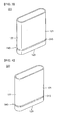
- FIG. 3 is a perspective view of a can according to a second embodiment of the present invention.
- FIG. 4 is a perspective view of a can according to a third embodiment of the present invention.
- FIG. 5 is a perspective view of a can according to a fourth embodiment of the present invention.
- FIG. 6 is a perspective view of a can according to a fifth embodiment of the present invention.
- FIG. 7 is a perspective view of a can according to a sixth embodiment of the present invention.
- FIG. 8 is an exploded perspective view of a lithium secondary battery according to another embodiment of the present invention.
- FIG. 1 is an exploded perspective view of a lithium secondary battery according to a first embodiment of the present invention and FIG. 2a is a perspective view of the can of the secondary battery and FIG. 2b is a sectional view taken along ⁇ I-I' line of FIG. 2a .
- a lithium secondary battery 100 includes an electrode assembly 110, a can 120 and a cap assembly 130.
- a relatively thin notched part 140 is formed at a lower part of the can 120.
- the notched part 140 serves as a sacrificial structure during vertical compression the lithium secondary battery 100. During such compression (i.e. during general use or during a compression test), the notched part 140 is ruptured and thus, the electrode assembly 110 is discharged downward from the can 120.
- the lithium secondary battery 100 prevents a short between electrodes at an upper part of the electrode assembly 110 by discharging the electrode assembly 110 downward by using the can 120 provided with the notched part 140 at the lower part thereof during the vertical compression.
- the electrode assembly 110 includes a cathode plate 111, an anode plate 112 and a separator 113 interposed between the cathode plate 111 and anode plate 112.
- the electrode assembly 110 further includes a cathode tab 114 and an anode tab 115 each having ends extending from an upper part of the electrode assembly 110 and fixed.
- the cathode tab 114 is withdrawn out of the cathode plate 111 and the anode tab 115 is withdrawn out of the anode plate 112.
- the cathode and anode tabs 114 and 115 may be made of aluminum (Al), nickel (Ni) or copper (Cu).
- the cathode tab 114 is made of aluminum (AI) and the anode tab 115 is made of nickel (Ni).
- an insulation tape 116 is wound on the parts of the cathode and anode tabs 114 and 115 extending from the upper part of the electrode assembly 110 to prevent a short between the cathode and anode plates 111 and 112.
- the electrode assembly 110 is usually formed by interposing the separator 113 between the cathode and anode plates 111 and 112 to insulate them from each other and winding them together in a jelly-roll structure.
- Cathode and anode active materials are respectively coated on the cathode and anode plates 111 and 112.
- the cathode active material may be a highly stable lithium manganese compound and the anode active material may be a carbonic compound.
- the present invention is not limited thereto.
- the can 120 includes a wide surface 121, a narrow surface 122 and a lower surface 123 sealing lower parts of the wide and narrow surfaces 121 and 122, thereby forming a space to receive the electrode assembly 110.
- the notched part 140 is formed at the lower part of the can 120.
- an opening is formed at an upper part of the can 120 and the electrode assembly 110 is inserted through the opening. The opening is sealed by the cap assembly 130.
- the can 120 is made of roughly a rectangular shape having one open end and can be made by a process, such as deep drawing.
- the can 120 may be made of a lightweight conductive metal such as aluminum (AI) or an aluminum alloy.
- the can 120 can function as a terminal by itself.
- the wide surface 121 is defined as a side wall having a relatively long width or length of a horizontal edge.
- a pair of wide surfaces 121 are spaced to face each other, thereby forming front and rear surfaces of the can 120.
- the narrow surface 122 is defined as a side wall having a relatively short width or length of a horizontal edge.
- the narrow surface 122 is continued to a side edge of the wide surface 121.
- the pair of narrow surfaces 122 are spaced to face each other, thereby forming both side surfaces of the can 120.
- the narrow surface 122 is formed round.
- the lower surface 123 corresponds to the upper opening of the can 120 and is sealed. In addition, the lower surface 123 is continued to the lower parts of the wide and narrow surfaces 121 and 122.
- the lower surface 123 supports structures or contents of the lithium secondary battery 100.
- the notched part 140 is formed in a shape of stripe parallel to the lower surface 123. In addition, the notched part 140 is formed at the lower part of the can 120, that is, the lower parts of the wide and narrow surfaces 121 and 122.
- the notched part 140 is formed of a rupture groove group 145 consisting of a plurality of rupture grooves 145a.
- the rupture groove group 145 further includes a space regions 145b.
- the space regions 145b is defined as a region that corresponds to a space between two adjacent rupture grooves 145a.
- the plurality of rupture groove 145a and space regions 145b are sequentially and repeatedly formed on the same line, thereby forming the rupture groove group 145.
- the space regions 145b are provided in portions of the wide and narrow surfaces 121 and 122 and thus has the same thickness (d1) as the wide and narrow surfaces 121 and 122.
- a width (w1) of the rupture grooves 145a is larger than a width (w2) of the space regions 145b. that is the reason that the entire rupture groove group 145 is easily ruptured when a force (Fa) is applied to the both narrow surface 122 in the vertical direction (z) during the vertical compression test and the electrode assembly 110 contained in the can 120 can be smoothly discharged downward. Accordingly, the width (w1) of the rupture groove 145a and the width (w2) of the space regions 145b are important factors that determine fracture strength in the vertical compression test.
- the electrode assembly 110 is discharged downward because the lower part of the electrode assembly 110 has a relatively simple structure and thus, the possibility of a short is relatively low.
- the cathode and anode tabs 114 and 115 extend from the upper part of the electrode assembly 110 and are electrically coupled to the cap assembly 130 in a complicated structure.
- the cathode tab 114 or anode tab 115 is respectively extended upward or downward from the electrode assembly 110, the lower part of the electrode assembly 110 has a relatively simple structure and thus, the possibility of a short is relatively low compared to the upper part of the electrode assembly 110.
- a depth (d2) of the rupture grooves 145a is 55 to 75% of a thickness(d1) of the wide or narrow surface of the can 120.
- the ratio of the depth (d2) to the thickness (d1) is another important factor that determines the fracture strength in the vertical compression test.
- the fracture strength of the rupture grooves 145a is lower than the welding strength between the can 120 and cap assembly 130 when they are welded together.
- the depth (d2) of the rupture grooves 145a is less than 55% of the thickness (d1) of the can 120, the cap assembly 130 may be opened before the entire rupture groove group 145 is ruptured and thus the electrode assembly 110 may be discharged upward in the vertical compression test.
- the rupture groove group 145 may be partially ruptured or may not be ruptured.
- the depth (d2) of the rupture grooves 145a is less than 55% of a thickness(d1) of the wide or narrow surface of the can 120, the fracture strength of the rupture grooves 145a is higher that welding strength between the can 120 and cap assembly 130.
- the depth (d2) of the rupture grooves 145a is more than 75% of a thickness(d1) of the wide or narrow surface of the can 120, the inside of the rupture groove 145a is bent to cause damage to the electrode assembly 110 during the assembling process of the lithium secondary battery 100.
- the can 120 may be partially crushed, or the part above the rupture groove group 145 may be downward crushed when the battery is pressurized to install structures such as the cap assembly 130 at the upper part.
- the width (w1) of the rupture grooves 145a is larger than the width (w2) of the space regions 145b and the depth (d2) of the rupture groove 145a is 55 to 75% of a thickness(d1) of the wide or narrow surface of the can 120, the electrode assembly 110 can be smoothly discharged downward in the vertical compression test and thus a short between electrodes can be prevented.
- the safety of the lithium secondary battery 100 is improved.
- the notched part 140 consists of one rupture groove group 145 in FIGS. 1 , 2a and 2b .
- the present invention is not limited thereto.
- the notched part 140 may further include another rupture groove group 145 of a stripe shape at different positions of the wide and narrow surfaces 121 and 122 in a direction parallel to the rupture groove group 145 formed at the lower part of the can 120.
- the number of rupture groove groups 145 is not limited.
- the cap assembly 130 is provided at the upper part of the can 120 and finished by welding.
- the welding strength between the cap assembly 130 and can 120 is greater than the fracture strength of the notched part 140.
- the cap assembly 130 includes a cap plate 131, a gasket 132, an electrode terminal 133, an insulation plate 134, a terminal plate 135, an insulation case 136 and a stopper 137.
- the cap plate 131 includes a terminal hole 131a and an electrolyte injection hole 131 b.
- the electrode terminal 133 can be inserted through the terminal hole 131 a.
- the electrode terminal 133 is assembled with the gasket 132 made of an insulating material at a side wall thereof and then inserted into the terminal hole 131a to insulate the metallic cap plate 131 and electrode terminal 133 from each other.
- the electrolyte injection hole 131b is provided at one side of the cap plate 131 to inject electrolyte into the can 120. After the electrolyte is injected through the electrolyte injection hole 131 b, the electrolyte injection hole 131 b is sealed with the stopper 137 to prevent leakage of the electrolyte.
- the insulation plate 134 is provided under the cap plate 131.
- the terminal plate 135 is provided under the insulation plate 134. Thus, the insulation plate 134 insulates the cap plate 131 from the terminal plate 135.
- the terminal plate 135 is combined with a lower end of the electrode terminal 133. Accordingly, the anode plate 112 of the electrode assembly 110 is electrically coupled to the electrode terminal 133 through the anode tab 115 and terminal plate 135. The cathode plate 111 of the electrode assembly 110 is electrically coupled to the cap plate 131 or can 120 through the cathode tab 114.
- the insulation case 136 is provided under the terminal plate 135.
- the insulation case 136 includes an anode tab aperture 136a, a cathode tab aperture 136b and an electrolyte injection hole 136c.
- the stopper 137 is used to seal the electrolyte injection hole 131b after the electrolyte is injected into the electrolyte injection hole 131b.
- the electrolyte injection hole 131 b may be sealed by pressing a ball therein.
- the lithium secondary battery 100 includes the can provided with the notched part 140 at the lower part thereof.
- the lithium secondary battery 100 can be smoothly discharged downward in the vertical compression test.
- a short between the electrodes can be prevented by smoothly discharging the electrode assembly 110 downward.
- the safety of the lithium secondary battery 100 is improved.
- a lithium secondary battery according to a second embodiment of the present invention is explained below.
- FIG. 3 is a perspective view of a can according to the second embodiment.
- the lithium secondary battery of the second embodiment has the same elements as the lithium secondary battery of the first embodiment except for a structure of a notched part. Accordingly, the same drawing reference numerals are used for the same elements and a detailed explanation thereof has been omitted. Thus, a notched part which different from the first embodiment is mainly explained below.
- the lithium secondary battery 100 includes an electrode assembly 110, a can 220 and a cap assembly 130.
- a relatively thin notched part 240 is formed at a lower part of the can 220.
- the can 220 is formed by the same material and process as the can 120 of the first embodiment and performs the same function.
- the can 220 includes a wide surface 121, a narrow surface 122 and a lower surface 123 sealing lower parts of the wide and narrow surfaces 121 and 122, thereby forming space to receive the electrode assembly 110.
- the can 220 further includes the notched part 240.
- the notched part 240 is formed at the lower part of the can 220, that is, at the lower parts of the wide and narrow surfaces 121 and 122. In addition, the notched part 240 is formed at the lower part of the can 220 in a shape of stripe parallel to the lower surface 123. The notched part 240 is formed in a shape of a trench consisting of a linearly continuous rupture groove 245.
- the notched part 240 is formed of single rupture groove 245 differently from the notched part 140 of the first embodiment in which the notched part 140 is formed of the rupture groove group 145 including the plurality of rupture grooves 145a and space regions 145b.
- the lithium secondary battery of the second embodiment is more easily ruptured in the vertical compression test than the first embodiment and thus can discharge the electrode assembly 110 more smoothly.
- a lithium secondary battery according to a third embodiment of the present invention is explained below.
- FIG. 4 is a perspective view of a can according to the third embodiment.
- the lithium secondary battery of the third embodiment has the same elements as the lithium secondary battery of the first embodiment except for a structure of a notched part. Accordingly, the same drawing reference numerals are used for the same elements and a detailed explanation thereof has been omitted. Thus, a notched part different from the first embodiment is mainly explained below.
- the lithium secondary battery 100 includes an electrode assembly 110, a can 320 and a cap assembly 130.
- a relatively thin notched part 340 is formed at a lower part of the can 320.
- the can 320 is formed by the same material and process as the can 120 of the first embodiment and performs the same function.
- the can 320 includes a wide surface 121, a narrow surface 122 and a lower surface 123 sealing lower parts of the wide and narrow surfaces 121 and 122, thereby forming space to receive the electrode assembly 110.
- the can 320 further includes the notched part 340.
- the notched part 340 is formed at the lower part of the can 320, that is, at the lower parts of the wide and narrow surfaces 121 and 122. In addition, the notched part 340 is formed at the lower part of the can 320 in a shape of a stripe parallel to the lower surface 123. The notched part 340 is formed as a trench having a zigzag continuous rupture groove 345 in a direction parallel to the lower surface.
- the notched part 340 is formed of single zigzag rupture groove 345 differently from the notched part 140 of the first embodiment in which the notched part 140 is formed of the rupture groove group 145 including the plurality of rupture grooves 145a and space regions 145b.
- the lithium secondary battery of the third embodiment is more easily ruptured in the vertical compression test than the first embodiment and thus can discharge the electrode assembly 110 more smoothly.
- a lithium secondary battery according to a fourth embodiment of the present invention is explained below.
- FIG. 5 is a perspective view of a can according to the fourth embodiment.
- the lithium secondary battery of the fourth embodiment has the same elements as the lithium secondary battery of the first embodiment except for a formation location of a notched part. Accordingly, the same drawing reference numerals are used for the same elements and a detailed explanation thereof has been omitted. Thus, a notched part different from the first embodiment is mainly explained below.
- the lithium secondary battery 100 includes an electrode assembly 110, a can 420 and a cap assembly 130.
- a relatively thin notched part 440 is formed at a lower part of the can 420.
- the can 420 is formed by the same material and process as the can 120 of the first embodiment and performs the same function.
- the can 420 includes a wide surface 121, a narrow surface 122 and a lower surface 123 sealing lower parts of the wide and narrow surfaces 121 and 122, thereby forming a space to receive the electrode assembly 110.
- the can 420 further includes the notched part 440.
- the notched part 440 is formed at the lower surface 123 of the can 420.
- the notched part 440 is formed of a rupture groove group 445 consisting of a plurality of rupture grooves 445a.
- the rupture groove group 445 further includes space regions 445b.
- the rupture groove group 445 is formed of the plurality of rupture groove 445a and space regions 445b that are sequentially and repeatedly formed on the same line. It is desirable that a width (w3) of the space regions 445b is larger than a width (w4) of the space regions 145b. In addition, it is desirable that a depth of the rupture grooves 445a is 55 to 75% of a thickness of the lower surface of the can 420.
- the notched part 440 is formed on the lower surface 123 of the can 420 differently from the notched part 140 of the first embodiment in which the notched part 140 is formed at the lower side wall of the can 120.
- the lithium secondary battery of the fourth embodiment can discharge the electrode assembly 110 in the vertical compression test and improve the strength of the wide and narrow surfaces 121 and 122 more than the first embodiment.
- a lithium secondary battery according to a fifth embodiment of the present invention is explained below.
- FIG. 6 is a perspective view of a can according to the fifth embodiment.
- the lithium secondary battery of the fifth embodiment has the same elements as the lithium secondary battery of the fourth embodiment except for a structure of a notched part. Accordingly, the same drawing reference numerals are used for the same elements and a detailed explanation thereof has been omitted. Thus, a notched part different from the fourth embodiment is mainly explained below.
- the lithium secondary battery 100 includes an electrode assembly 110, a can 520 and a cap assembly 130.
- a relatively thin notched part 540 is formed at a lower part of the can 520.
- the can 520 is formed by the same material and process as the can 420 of the fourth embodiment and performs the same function.
- the can 520 includes a wide surface 121, a narrow surface 122 and a lower surface 123 sealing lower parts of the wide and narrow surfaces 121 and 122, thereby forming a space to receive the electrode assembly 110.
- the can 520 further includes the notched part 540.
- the notched part 540 is formed at the lower surface 123 of the can 320.
- the notched part 540 is formed as a trench of a linearly continuous rupture groove 545.
- the notched part 540 is formed of single linear rupture groove 545 differently from the notched part 440 of the fourth embodiment that is formed of the rupture groove group 445 including the plurality of rupture grooves 445a and space regions 445b.
- the rupture groove 545 of the lithium secondary battery of the fifth embodiment is more easily ruptured in the vertical compression test than the fourth embodiment and thus can discharge the electrode assembly 110 more smoothly.
- a lithium secondary battery according to a sixth embodiment of the present invention is explained below.
- FIG. 7 is a perspective view of a can according to the sixth embodiment.
- the lithium secondary battery of the sixth embodiment has the same elements as the lithium secondary battery of the fourth embodiment except for a structure of a notched part. Accordingly, the same drawing reference numerals are used for the same elements and an explanation thereof has been omitted. Thus, a notched part different from the fourth embodiment is mainly explained below.
- the lithium secondary battery 100 includes an electrode assembly 110, a can 620 and a cap assembly 130.
- a relatively thin notched part 640 is formed at a lower part of the can 620.
- the can 620 is formed by the same material and process as the can 420 of the fourth embodiment and performs the same function.
- the can 620 includes a wide surface 121, a narrow surface 122 and a lower surface 123 sealing lower parts of the wide and narrow surfaces 121 and 122, thereby forming a space to receive the electrode assembly 110.
- the can 620 further includes the notched part 640.
- the notched part 640 is formed at the lower surface 123 of the can 620.
- the notched part 640 is formed as a trench of a zigzag continuous rupture groove 545 in a direction parallel to the lower surface 123.
- the notched part 640 is formed of single zigzag rupture groove 645 differently from the notched part 440 of the fourth embodiment that is formed of the rupture groove group 445 including the plurality of rupture grooves 445a and space regions 445b.
- the rupture groove 645 of the lithium secondary battery of the sixth embodiment is more easily ruptured in the vertical compression test than the fourth embodiment and thus can discharge the electrode assembly 110 more smoothly.
- a lithium secondary battery according to another embodiment of the present invention is explained below.
- FIG. 8 is an exploded perspective view of the lithium secondary battery according to another embodiment.
- the lithium secondary battery 700 is a cylindrical battery.
- the lithium secondary battery 700 includes an electrode assembly 710, a cylindrical can 720 and a cap assembly 730 sealing an upper opening of the cylindrical can 720.
- the cap assembly 730 includes a cap up 731, a cap up 731 provided under the cap up 731, a safety vent 733 provided under the secondary protection device 732, an insulator 734 provided under the safety vent 733, a cap down 735 provided under the insulator 734 and a gasket 736 surrounding the above elements.
- the lithium secondary battery 700 includes an upper insulation plate 750.
- the lithium secondary battery 700 further includes a center pin 760 that is inserted into the electrode assembly 710 to prevent deformation thereof.
- the lithium secondary battery 700 further includes a lower insulation plate 770 formed under the electrode assembly 710.
- a notched part 740 is formed at a lower part of the cylindrical can 720.
- the notched part 740 is formed to surround a circumference of the lower part of the cylindrical can 720, but may alternatively be formed on a bottom surface of the cylindrical can 720.
- the notched part 740 may also alternatively be formed as a linear or zigzag continuous rupture groove.
- the described embodiments show their respective sacrificial parts as located in an end region opposite to that of the electrode assembly, this is not absolutely essential.
- the sacrificial part could be located in a region much closer to the electrode assembly, as long as it is sufficiently far from the electrode assembly that it does not cause a short between the electrodes and/or the electrode assembly when it is sacrificed during compression.
- the sacrificial part need not take the form of a notch or notches. It is possible for the sacrificial part to take other forms that result in localised structural weakening.
- the sacrificial part could be formed by a variation in the deep-drawing process or by chemical treatment.
- the lithium secondary battery according to the present invention produces the following effects.
- the electrode assembly can be discharged downward during the vertical compression test by using the can provided with a sacrificial formation separated therefrom.
- the electrode assembly can be discharged downward during the vertical compression test, thereby preventing a short between the electrodes at the upper part of the electrode assembly.
Landscapes
- Chemical & Material Sciences (AREA)
- Chemical Kinetics & Catalysis (AREA)
- Electrochemistry (AREA)
- General Chemical & Material Sciences (AREA)
- Engineering & Computer Science (AREA)
- Manufacturing & Machinery (AREA)
- Sealing Battery Cases Or Jackets (AREA)
- Secondary Cells (AREA)
- Gas Exhaust Devices For Batteries (AREA)
Abstract
Description
- The present invention relates to a lithium secondary battery.
- Generally, a lithium secondary battery is manufactured by forming an electrode assembly by winding cathode and anode plates and a separator interposed between the electrodes together in a jelly-roll structure and arranging the electrode assembly in a can with electrolyte and then sealing an upper opening of the can with a cap assembly.
- The can has a roughly rectangular shape in a rectangular type secondary battery and is a metal container made of lightweight conductive metal, such as aluminum (AI) or an aluminum alloy. Therefore, the can functions as one terminal of the battery. The can may be formed by a deep drawing process.
- During compression, such batteries are susceptible to damage in the area of the electrode assembly. This can lead to a short between the electrodes and the electrode assembly and the electrodes or between the electrodes themselves. The consequences of this can be damaging and sometimes even dangerous. The present invention sets out to provide a secondary batter that is not susceptible to the above risks.
- According to one aspect of the present invention, a secondary battery is provided, which includes: an electrode assembly; a can having an upper opening to receive the electrode assembly and a notched part at a lower part thereof; and a cap assembly to seal the can.
- The electrode assembly may be in a first end region of the battery and the notched part in an opposite end region of the assembly.
- The can may include a wide surface, a narrow surface and a lower surface and the notched part may be formed on the wide and narrow surfaces in a shape of a line parallel to the lower surface.
- The notched part may be formed of a rupture groove group including a plurality of rupture grooves.
- A space between any two of adjacent rupture grooves may be narrower than a width of any one of the plurality of rupture grooves.
- A depth of the rupture grooves may be 55 to 75% of a thickness of wide or narrow surface of the can.
- A rupture strength of the rupture grooves may be lower than a welding strength between the can and cap assembly, when the cap assembly is welded to the can.
- A plurality of notched parts may be formed in a direction parallel to the lower surface.
- The notched part may be formed in a trench including a linearly continuous rupture groove.
- In addition, the notched part may be formed in a trench including a zigzag continuous rupture groove in a direction parallel to the lower surface.
- The can may include a wide surface, a narrow surface and a lower surface and the notched part may be formed on the lower surface in a shape of a line.
- The notched part may be formed of a rupture groove group including a plurality of rupture grooves.
- A space between any two of adjacent rupture grooves may be narrower than a width of any one of the plurality of rupture grooves.
- A depth of the rupture grooves may be 55 to 75% of a thickness of the lower surface of the can.
- The notched part may be formed in a trench including linearly continuous rupture grooves.
- In addition, the notched part may be formed in a trench including zigzag continuous rupture grooves in a direction parallel to the lower surface.
- The can may be a cylindrical or polygonal can.
- A more complete appreciation of the present invention, and many of the attendant advantages thereof, will be readily apparent as the present invention becomes better understood by reference to the following detailed description when considered in conjunction with the accompanying drawings in which like reference symbols indicated the same or similar components, wherein:
-
FIG. 1 is an exploded perspective view of a secondary battery according to one a first embodiment of the present invention; -
FIG. 2a is a perspective view of a can of the secondary battery ofFigure 1 ; -
FIG. 2b is a sectional view taken along 'I-I' line ofFIG. 2a ; -
FIG. 3 is a perspective view of a can according to a second embodiment of the present invention; -
FIG. 4 is a perspective view of a can according to a third embodiment of the present invention; -
FIG. 5 is a perspective view of a can according to a fourth embodiment of the present invention; -
FIG. 6 is a perspective view of a can according to a fifth embodiment of the present invention; -
FIG. 7 is a perspective view of a can according to a sixth embodiment of the present invention; and -
FIG. 8 is an exploded perspective view of a lithium secondary battery according to another embodiment of the present invention. - Hereinafter, embodiments of the present invention are described in detail with reference to the accompanying drawings. The aspects and features of the present invention and methods for achieving the aspects and features will be apparent by referring to the embodiments described in detail below with reference to the accompanying drawings. However, the present invention is not limited to the embodiments disclosed hereinafter, but can be implemented in diverse forms. The matters defined in the description, such as the detailed construction and elements, are merely specific details provided to assist those of ordinary skill in the art in a comprehensive understanding of the present invention, and the present invention is only defined within the scope of the appended claims. In the entire description of the present invention, the same drawing reference numerals are used for the same elements across various figures.
-
FIG. 1 is an exploded perspective view of a lithium secondary battery according to a first embodiment of the present invention andFIG. 2a is a perspective view of the can of the secondary battery andFIG. 2b is a sectional view taken along `I-I' line ofFIG. 2a . - Referring to
FIGS. 1 ,2a and 2b , a lithiumsecondary battery 100 includes anelectrode assembly 110, acan 120 and acap assembly 130. A relatively thin notchedpart 140 is formed at a lower part of thecan 120. Thenotched part 140 serves as a sacrificial structure during vertical compression the lithiumsecondary battery 100. During such compression (i.e. during general use or during a compression test), thenotched part 140 is ruptured and thus, theelectrode assembly 110 is discharged downward from thecan 120. In other words, the lithiumsecondary battery 100 prevents a short between electrodes at an upper part of theelectrode assembly 110 by discharging theelectrode assembly 110 downward by using thecan 120 provided with thenotched part 140 at the lower part thereof during the vertical compression. - The
electrode assembly 110 includes acathode plate 111, ananode plate 112 and aseparator 113 interposed between thecathode plate 111 andanode plate 112. In addition, theelectrode assembly 110 further includes acathode tab 114 and ananode tab 115 each having ends extending from an upper part of theelectrode assembly 110 and fixed. Thecathode tab 114 is withdrawn out of thecathode plate 111 and theanode tab 115 is withdrawn out of theanode plate 112. In addition, the cathode andanode tabs cathode tab 114 is made of aluminum (AI) and theanode tab 115 is made of nickel (Ni). In addition, aninsulation tape 116 is wound on the parts of the cathode andanode tabs electrode assembly 110 to prevent a short between the cathode andanode plates electrode assembly 110 is usually formed by interposing theseparator 113 between the cathode andanode plates anode plates - The can 120 includes a
wide surface 121, anarrow surface 122 and alower surface 123 sealing lower parts of the wide andnarrow surfaces electrode assembly 110. The notchedpart 140 is formed at the lower part of thecan 120. In addition, an opening is formed at an upper part of thecan 120 and theelectrode assembly 110 is inserted through the opening. The opening is sealed by thecap assembly 130. In other words, in a rectangular secondary battery, thecan 120 is made of roughly a rectangular shape having one open end and can be made by a process, such as deep drawing. The can 120 may be made of a lightweight conductive metal such as aluminum (AI) or an aluminum alloy. The can 120 can function as a terminal by itself. - In the
can 120, thewide surface 121 is defined as a side wall having a relatively long width or length of a horizontal edge. A pair ofwide surfaces 121 are spaced to face each other, thereby forming front and rear surfaces of thecan 120. Thenarrow surface 122 is defined as a side wall having a relatively short width or length of a horizontal edge. Thenarrow surface 122 is continued to a side edge of thewide surface 121. The pair ofnarrow surfaces 122 are spaced to face each other, thereby forming both side surfaces of thecan 120. Thenarrow surface 122 is formed round. Thelower surface 123 corresponds to the upper opening of thecan 120 and is sealed. In addition, thelower surface 123 is continued to the lower parts of the wide andnarrow surfaces lower surface 123 supports structures or contents of the lithiumsecondary battery 100. - The notched
part 140 is formed in a shape of stripe parallel to thelower surface 123. In addition, the notchedpart 140 is formed at the lower part of thecan 120, that is, the lower parts of the wide andnarrow surfaces part 140 is formed of arupture groove group 145 consisting of a plurality ofrupture grooves 145a. Therupture groove group 145 further includes aspace regions 145b. - The
space regions 145b is defined as a region that corresponds to a space between twoadjacent rupture grooves 145a. In other words, the plurality ofrupture groove 145a andspace regions 145b are sequentially and repeatedly formed on the same line, thereby forming therupture groove group 145. Thespace regions 145b are provided in portions of the wide andnarrow surfaces narrow surfaces - On the other hand, it is desirable that a width (w1) of the
rupture grooves 145a is larger than a width (w2) of the space regions 145b. that is the reason that the entirerupture groove group 145 is easily ruptured when a force (Fa) is applied to the bothnarrow surface 122 in the vertical direction (z) during the vertical compression test and theelectrode assembly 110 contained in thecan 120 can be smoothly discharged downward. Accordingly, the width (w1) of therupture groove 145a and the width (w2) of thespace regions 145b are important factors that determine fracture strength in the vertical compression test. Theelectrode assembly 110 is discharged downward because the lower part of theelectrode assembly 110 has a relatively simple structure and thus, the possibility of a short is relatively low. - On the other hand, the cathode and
anode tabs electrode assembly 110 and are electrically coupled to thecap assembly 130 in a complicated structure. In addition, even when thecathode tab 114 oranode tab 115 is respectively extended upward or downward from theelectrode assembly 110, the lower part of theelectrode assembly 110 has a relatively simple structure and thus, the possibility of a short is relatively low compared to the upper part of theelectrode assembly 110. - On the other hand, when the width (w2) of the
space regions 145b is larger than the width (w1) of therupture grooves 145a, thecap assembly 130 welded to the upper part of thecan 120 may be opened before the entirerupture groove group 145 is ruptured and thus theelectrode assembly 110 may be discharged upward in the vertical compression test. Accordingly, a short between electrodes or a fire may occur as in the conventional battery. It is desirable that a depth (d2) of therupture grooves 145a is 55 to 75% of a thickness(d1) of the wide or narrow surface of thecan 120. The ratio of the depth (d2) to the thickness (d1) is another important factor that determines the fracture strength in the vertical compression test. It is desirable that the fracture strength of therupture grooves 145a is lower than the welding strength between thecan 120 andcap assembly 130 when they are welded together. When the depth (d2) of therupture grooves 145a is less than 55% of the thickness (d1) of thecan 120, thecap assembly 130 may be opened before the entirerupture groove group 145 is ruptured and thus theelectrode assembly 110 may be discharged upward in the vertical compression test. - In addition, the
rupture groove group 145 may be partially ruptured or may not be ruptured. In other words, when the depth (d2) of therupture grooves 145a is less than 55% of a thickness(d1) of the wide or narrow surface of thecan 120, the fracture strength of therupture grooves 145a is higher that welding strength between thecan 120 andcap assembly 130. On the other hand, when the depth (d2) of therupture grooves 145a is more than 75% of a thickness(d1) of the wide or narrow surface of thecan 120, the inside of therupture groove 145a is bent to cause damage to theelectrode assembly 110 during the assembling process of the lithiumsecondary battery 100. In addition, thecan 120 may be partially crushed, or the part above therupture groove group 145 may be downward crushed when the battery is pressurized to install structures such as thecap assembly 130 at the upper part. Thus, when the width (w1) of therupture grooves 145a is larger than the width (w2) of thespace regions 145b and the depth (d2) of therupture groove 145a is 55 to 75% of a thickness(d1) of the wide or narrow surface of thecan 120, theelectrode assembly 110 can be smoothly discharged downward in the vertical compression test and thus a short between electrodes can be prevented. Thus, the safety of the lithiumsecondary battery 100 is improved. - On the other hand, the notched
part 140 consists of onerupture groove group 145 inFIGS. 1 ,2a and 2b . However, the present invention is not limited thereto. For example, the notchedpart 140 may further include anotherrupture groove group 145 of a stripe shape at different positions of the wide andnarrow surfaces rupture groove group 145 formed at the lower part of thecan 120. In other words, the number ofrupture groove groups 145 is not limited. - The
cap assembly 130 is provided at the upper part of thecan 120 and finished by welding. The welding strength between thecap assembly 130 and can 120 is greater than the fracture strength of the notchedpart 140. Thecap assembly 130 includes acap plate 131, agasket 132, anelectrode terminal 133, aninsulation plate 134, aterminal plate 135, aninsulation case 136 and astopper 137. - The
cap plate 131 includes aterminal hole 131a and anelectrolyte injection hole 131 b. Theelectrode terminal 133 can be inserted through theterminal hole 131 a. Theelectrode terminal 133 is assembled with thegasket 132 made of an insulating material at a side wall thereof and then inserted into theterminal hole 131a to insulate themetallic cap plate 131 andelectrode terminal 133 from each other. - On the other hand, the
electrolyte injection hole 131b is provided at one side of thecap plate 131 to inject electrolyte into thecan 120. After the electrolyte is injected through theelectrolyte injection hole 131 b, theelectrolyte injection hole 131 b is sealed with thestopper 137 to prevent leakage of the electrolyte. Theinsulation plate 134 is provided under thecap plate 131. Theterminal plate 135 is provided under theinsulation plate 134. Thus, theinsulation plate 134 insulates thecap plate 131 from theterminal plate 135. - On the other hand, the
terminal plate 135 is combined with a lower end of theelectrode terminal 133. Accordingly, theanode plate 112 of theelectrode assembly 110 is electrically coupled to theelectrode terminal 133 through theanode tab 115 andterminal plate 135. Thecathode plate 111 of theelectrode assembly 110 is electrically coupled to thecap plate 131 or can 120 through thecathode tab 114. - The
insulation case 136 is provided under theterminal plate 135. Theinsulation case 136 includes ananode tab aperture 136a, acathode tab aperture 136b and anelectrolyte injection hole 136c. - The
stopper 137 is used to seal theelectrolyte injection hole 131b after the electrolyte is injected into theelectrolyte injection hole 131b. In addition to thestopper 137, theelectrolyte injection hole 131 b may be sealed by pressing a ball therein. - As described above, the lithium
secondary battery 100 includes the can provided with the notchedpart 140 at the lower part thereof. Thus, the lithiumsecondary battery 100 can be smoothly discharged downward in the vertical compression test. In addition, a short between the electrodes can be prevented by smoothly discharging theelectrode assembly 110 downward. Thus, the safety of the lithiumsecondary battery 100 is improved. - A lithium secondary battery according to a second embodiment of the present invention is explained below.
-
FIG. 3 is a perspective view of a can according to the second embodiment. - The lithium secondary battery of the second embodiment has the same elements as the lithium secondary battery of the first embodiment except for a structure of a notched part. Accordingly, the same drawing reference numerals are used for the same elements and a detailed explanation thereof has been omitted. Thus, a notched part which different from the first embodiment is mainly explained below.
- The lithium
secondary battery 100 includes anelectrode assembly 110, a can 220 and acap assembly 130. A relatively thin notchedpart 240 is formed at a lower part of thecan 220. The can 220 is formed by the same material and process as thecan 120 of the first embodiment and performs the same function. - Referring to
FIG. 3 , thecan 220 includes awide surface 121, anarrow surface 122 and alower surface 123 sealing lower parts of the wide andnarrow surfaces electrode assembly 110. The can 220 further includes the notchedpart 240. - The notched
part 240 is formed at the lower part of thecan 220, that is, at the lower parts of the wide andnarrow surfaces part 240 is formed at the lower part of thecan 220 in a shape of stripe parallel to thelower surface 123. The notchedpart 240 is formed in a shape of a trench consisting of a linearlycontinuous rupture groove 245. - The notched
part 240 is formed ofsingle rupture groove 245 differently from the notchedpart 140 of the first embodiment in which the notchedpart 140 is formed of therupture groove group 145 including the plurality ofrupture grooves 145a andspace regions 145b. Thus, the lithium secondary battery of the second embodiment is more easily ruptured in the vertical compression test than the first embodiment and thus can discharge theelectrode assembly 110 more smoothly. - A lithium secondary battery according to a third embodiment of the present invention is explained below.
-
FIG. 4 is a perspective view of a can according to the third embodiment. - The lithium secondary battery of the third embodiment has the same elements as the lithium secondary battery of the first embodiment except for a structure of a notched part. Accordingly, the same drawing reference numerals are used for the same elements and a detailed explanation thereof has been omitted. Thus, a notched part different from the first embodiment is mainly explained below.
- The lithium
secondary battery 100 includes anelectrode assembly 110, a can 320 and acap assembly 130. A relatively thin notchedpart 340 is formed at a lower part of thecan 320. The can 320 is formed by the same material and process as thecan 120 of the first embodiment and performs the same function. - Referring to
FIG. 4 , thecan 320 includes awide surface 121, anarrow surface 122 and alower surface 123 sealing lower parts of the wide andnarrow surfaces electrode assembly 110. The can 320 further includes the notchedpart 340. - The notched
part 340 is formed at the lower part of thecan 320, that is, at the lower parts of the wide andnarrow surfaces part 340 is formed at the lower part of thecan 320 in a shape of a stripe parallel to thelower surface 123. The notchedpart 340 is formed as a trench having a zigzagcontinuous rupture groove 345 in a direction parallel to the lower surface. - The notched
part 340 is formed of singlezigzag rupture groove 345 differently from the notchedpart 140 of the first embodiment in which the notchedpart 140 is formed of therupture groove group 145 including the plurality ofrupture grooves 145a andspace regions 145b. Thus, the lithium secondary battery of the third embodiment is more easily ruptured in the vertical compression test than the first embodiment and thus can discharge theelectrode assembly 110 more smoothly. - A lithium secondary battery according to a fourth embodiment of the present invention is explained below.
-
FIG. 5 is a perspective view of a can according to the fourth embodiment. - The lithium secondary battery of the fourth embodiment has the same elements as the lithium secondary battery of the first embodiment except for a formation location of a notched part. Accordingly, the same drawing reference numerals are used for the same elements and a detailed explanation thereof has been omitted. Thus, a notched part different from the first embodiment is mainly explained below.
- The lithium
secondary battery 100 includes anelectrode assembly 110, a can 420 and acap assembly 130. A relatively thin notchedpart 440 is formed at a lower part of the can 420. The can 420 is formed by the same material and process as thecan 120 of the first embodiment and performs the same function. - Referring to
FIG. 5 , the can 420 includes awide surface 121, anarrow surface 122 and alower surface 123 sealing lower parts of the wide andnarrow surfaces electrode assembly 110. The can 420 further includes the notchedpart 440. - The notched
part 440 is formed at thelower surface 123 of the can 420. The notchedpart 440 is formed of arupture groove group 445 consisting of a plurality ofrupture grooves 445a. Therupture groove group 445 further includesspace regions 445b. Therupture groove group 445 is formed of the plurality ofrupture groove 445a andspace regions 445b that are sequentially and repeatedly formed on the same line. It is desirable that a width (w3) of thespace regions 445b is larger than a width (w4) of thespace regions 145b. In addition, it is desirable that a depth of therupture grooves 445a is 55 to 75% of a thickness of the lower surface of the can 420. - The notched
part 440 is formed on thelower surface 123 of the can 420 differently from the notchedpart 140 of the first embodiment in which the notchedpart 140 is formed at the lower side wall of thecan 120. Thus, the lithium secondary battery of the fourth embodiment can discharge theelectrode assembly 110 in the vertical compression test and improve the strength of the wide andnarrow surfaces - A lithium secondary battery according to a fifth embodiment of the present invention is explained below.
-
FIG. 6 is a perspective view of a can according to the fifth embodiment. - The lithium secondary battery of the fifth embodiment has the same elements as the lithium secondary battery of the fourth embodiment except for a structure of a notched part. Accordingly, the same drawing reference numerals are used for the same elements and a detailed explanation thereof has been omitted. Thus, a notched part different from the fourth embodiment is mainly explained below.
- The lithium
secondary battery 100 includes anelectrode assembly 110, a can 520 and acap assembly 130. A relatively thin notchedpart 540 is formed at a lower part of thecan 520. The can 520 is formed by the same material and process as the can 420 of the fourth embodiment and performs the same function. - Referring to
FIG. 6 , thecan 520 includes awide surface 121, anarrow surface 122 and alower surface 123 sealing lower parts of the wide andnarrow surfaces electrode assembly 110. The can 520 further includes the notchedpart 540. - The notched
part 540 is formed at thelower surface 123 of thecan 320. The notchedpart 540 is formed as a trench of a linearlycontinuous rupture groove 545. - The notched
part 540 is formed of singlelinear rupture groove 545 differently from the notchedpart 440 of the fourth embodiment that is formed of therupture groove group 445 including the plurality ofrupture grooves 445a andspace regions 445b. Thus, therupture groove 545 of the lithium secondary battery of the fifth embodiment is more easily ruptured in the vertical compression test than the fourth embodiment and thus can discharge theelectrode assembly 110 more smoothly. - A lithium secondary battery according to a sixth embodiment of the present invention is explained below.
-
FIG. 7 is a perspective view of a can according to the sixth embodiment. - The lithium secondary battery of the sixth embodiment has the same elements as the lithium secondary battery of the fourth embodiment except for a structure of a notched part. Accordingly, the same drawing reference numerals are used for the same elements and an explanation thereof has been omitted. Thus, a notched part different from the fourth embodiment is mainly explained below.
- The lithium
secondary battery 100 includes anelectrode assembly 110, a can 620 and acap assembly 130. A relatively thin notchedpart 640 is formed at a lower part of thecan 620. The can 620 is formed by the same material and process as the can 420 of the fourth embodiment and performs the same function. - Referring to
FIG. 7 , thecan 620 includes awide surface 121, anarrow surface 122 and alower surface 123 sealing lower parts of the wide andnarrow surfaces electrode assembly 110. The can 620 further includes the notchedpart 640. - The notched
part 640 is formed at thelower surface 123 of thecan 620. The notchedpart 640 is formed as a trench of a zigzagcontinuous rupture groove 545 in a direction parallel to thelower surface 123. - The notched
part 640 is formed of singlezigzag rupture groove 645 differently from the notchedpart 440 of the fourth embodiment that is formed of therupture groove group 445 including the plurality ofrupture grooves 445a andspace regions 445b. Thus, therupture groove 645 of the lithium secondary battery of the sixth embodiment is more easily ruptured in the vertical compression test than the fourth embodiment and thus can discharge theelectrode assembly 110 more smoothly. - A lithium secondary battery according to another embodiment of the present invention is explained below.
-
FIG. 8 is an exploded perspective view of the lithium secondary battery according to another embodiment. - Referring to
FIG. 8 , the lithiumsecondary battery 700 is a cylindrical battery. The lithiumsecondary battery 700 includes anelectrode assembly 710, acylindrical can 720 and acap assembly 730 sealing an upper opening of thecylindrical can 720. Thecap assembly 730 includes a cap up 731, a cap up 731 provided under the cap up 731, asafety vent 733 provided under thesecondary protection device 732, aninsulator 734 provided under thesafety vent 733, a cap down 735 provided under theinsulator 734 and agasket 736 surrounding the above elements. In addition, the lithiumsecondary battery 700 includes anupper insulation plate 750. In addition, the lithiumsecondary battery 700 further includes acenter pin 760 that is inserted into theelectrode assembly 710 to prevent deformation thereof. In addition, the lithiumsecondary battery 700 further includes alower insulation plate 770 formed under theelectrode assembly 710. - In the lithium
secondary battery 700 having the above construction, a notchedpart 740 is formed at a lower part of thecylindrical can 720. The notchedpart 740 is formed to surround a circumference of the lower part of thecylindrical can 720, but may alternatively be formed on a bottom surface of thecylindrical can 720. The notchedpart 740 may also alternatively be formed as a linear or zigzag continuous rupture groove. Thus, similarly to the rectangular lithiumsecondary battery 100 according to the above embodiments, the notchedpart 740 of the lithiumsecondary battery 700 is ruptured in the vertical compression test and thus theelectrode assembly 710 can be smoothly discharged downward. In addition, a short between the electrodes can be prevented to improve the safety of the lithiumsecondary battery 700. - Although the described embodiments show their respective sacrificial parts as located in an end region opposite to that of the electrode assembly, this is not absolutely essential. In particular, the sacrificial part could be located in a region much closer to the electrode assembly, as long as it is sufficiently far from the electrode assembly that it does not cause a short between the electrodes and/or the electrode assembly when it is sacrificed during compression.
- It is also the case that the sacrificial part need not take the form of a notch or notches. It is possible for the sacrificial part to take other forms that result in localised structural weakening. For example, the sacrificial part could be formed by a variation in the deep-drawing process or by chemical treatment.
- As described above, the lithium secondary battery according to the present invention produces the following effects.
- First, the electrode assembly can be discharged downward during the vertical compression test by using the can provided with a sacrificial formation separated therefrom.
- Second, the electrode assembly can be discharged downward during the vertical compression test, thereby preventing a short between the electrodes at the upper part of the electrode assembly.
- Third, safety is improved by preventing a short between the electrodes.
- It should be understood by those of ordinary skill in the art that various replacements, modifications and changes in the form and details may be made therein without departing from the scope of the present invention as defined by the following claims. Therefore, it is to be appreciated that the above described embodiments are for purposes of illustration only and are not to be construed as being limitations of the present invention.
Claims (12)
- A secondary battery, comprising:an electrode assembly;a can having an upper opening to receive the electrode assembly and a sacrificial part at a lower part of the can; anda cap assembly to seal the can.
- The secondary battery according to claim 1, wherein the sacrificial part comprises a rupture groove group including a plurality of rupture grooves.
- The secondary battery according to claim 2, wherein a space between any two of adjacent rupture grooves is narrower than a width of any one of rupture grooves.
- The secondary battery according to claim 2 or 3, wherein the can and cap assembly are welded together and a rupture strength of the rupture grooves is lower than a welding strength between the can and cap assembly.
- The secondary battery according to any preceding claim, wherein the can comprises:a wide surface, a narrow surface and a lower surface, the sacrificial part being arranged on the wide and narrow surfaces in a shape of a line parallel to the lower surface.
- The secondary battery according to claim 5, wherein a plurality of sacrificial parts are arranged in a direction parallel to the lower surface.
- The secondary battery according to claim 5 or 6 , wherein a depth of the rupture grooves is in a range of 55 to 75% of a thickness of the wide or narrow surface of the can.
- The secondary battery according to claim 1 to 4, wherein the can comprises:a wide surface, a narrow surface and a lower surface and the sacrificial part is arranged on the lower surface in a shape of a line.
- The secondary battery according to claim 8, wherein a depth of the rupture grooves is in a range of 55 to 75% of a thickness of the lower surface of the can.
- The secondary battery according to any preceding claim, wherein the sacrificial part takes the form of a trench including a substantially linearly continuous rupture groove.
- The secondary battery according to any preceding claim, wherein the sacrificial part is arranged in a trench including a zigzag substantially continuous rupture groove in a direction parallel to the lower surface.
- The secondary battery according to any preceding claim, wherein the can comprises one of either a cylindrical can or a polygonal can.
Applications Claiming Priority (1)
| Application Number | Priority Date | Filing Date | Title |
|---|---|---|---|
| KR1020080053800A KR101023919B1 (en) | 2008-06-09 | 2008-06-09 | Lithium secondary battery |
Publications (2)
| Publication Number | Publication Date |
|---|---|
| EP2133934A1 true EP2133934A1 (en) | 2009-12-16 |
| EP2133934B1 EP2133934B1 (en) | 2019-04-17 |
Family
ID=40957983
Family Applications (1)
| Application Number | Title | Priority Date | Filing Date |
|---|---|---|---|
| EP09251517.0A Not-in-force EP2133934B1 (en) | 2008-06-09 | 2009-06-09 | Secondary battery |
Country Status (5)
| Country | Link |
|---|---|
| US (1) | US8147998B2 (en) |
| EP (1) | EP2133934B1 (en) |
| JP (1) | JP5113117B2 (en) |
| KR (1) | KR101023919B1 (en) |
| CN (1) | CN101604759B (en) |
Cited By (2)
| Publication number | Priority date | Publication date | Assignee | Title |
|---|---|---|---|---|
| EP2385565A1 (en) * | 2010-05-03 | 2011-11-09 | Samsung SDI Co., Ltd. | Rechargeable battery |
| EP4697462A1 (en) * | 2024-08-14 | 2026-02-18 | Samsung Sdi Co., Ltd. | Can for rechargeable battery, rechargeable battery including the same, and method for disassembling rechargeable battery |
Families Citing this family (25)
| Publication number | Priority date | Publication date | Assignee | Title |
|---|---|---|---|---|
| KR20110003866A (en) * | 2009-07-06 | 2011-01-13 | 에스비리모티브 주식회사 | Lithium ion battery |
| TWD142429S1 (en) * | 2010-03-09 | 2011-09-01 | 神戶製鋼所股份有限公司 | Bus bar for battery use |
| KR101907215B1 (en) * | 2012-08-08 | 2018-10-11 | 삼성에스디아이 주식회사 | Cylindrical lithium ion secondary battery |
| CN104380507B (en) * | 2012-11-30 | 2017-12-01 | 株式会社Lg 化学 | Negative electrode active material, lithium secondary battery comprising same, and method of manufacturing negative electrode active material |
| KR101440891B1 (en) | 2013-01-30 | 2014-09-17 | 삼성에스디아이 주식회사 | Rechargeable Battery |
| US9337451B2 (en) | 2013-07-30 | 2016-05-10 | Johnson Controls Technology Company | System and method for roller interconnection of battery cells |
| KR102069513B1 (en) * | 2015-10-07 | 2020-01-23 | 주식회사 엘지화학 | Secondary Battery Comprising a Planned Breaking Part and Method for Preparing the Same |
| JP6536354B2 (en) * | 2015-11-02 | 2019-07-03 | 株式会社村田製作所 | Battery, battery pack, electronic device, electric vehicle, power storage device and power system |
| KR102629177B1 (en) * | 2016-07-12 | 2024-01-26 | 삼성에스디아이 주식회사 | Secondary Battery |
| KR20180092444A (en) * | 2017-02-09 | 2018-08-20 | 주식회사 엘지화학 | A cylindrical type Li-ion secondary battery |
| KR101953228B1 (en) | 2017-09-18 | 2019-02-28 | 울산과학기술원 | Secondary Battery |
| KR101894385B1 (en) | 2017-10-11 | 2018-09-04 | 울산과학기술원 | Manufacturing Method of Anode for Secondary Battery and Anode for Secondary Battery Manufactured thereby |
| KR102019682B1 (en) * | 2017-12-08 | 2019-09-09 | 주식회사 엘지화학 | Secondary Battery Case Having Vent Filled with Thermoplastic Resin |
| KR102113499B1 (en) | 2018-08-30 | 2020-05-22 | 한국전력공사 | Electrode structure, manufacturing method of the same and secondary battery including the same |
| KR102455449B1 (en) | 2018-10-05 | 2022-10-18 | 주식회사 엘지에너지솔루션 | Rechargeable battery |
| KR102144571B1 (en) | 2018-10-24 | 2020-08-14 | 울산과학기술원 | Electrode structure, manufacturing method of the same, secondary battery including the same |
| KR20210099469A (en) * | 2020-02-04 | 2021-08-12 | 엘지전자 주식회사 | Battery cell |
| EP3965197B1 (en) | 2020-07-10 | 2023-03-15 | Contemporary Amperex Technology Co., Limited | Battery, electric device, and battery preparation method and device |
| CA3156564A1 (en) | 2020-07-10 | 2022-01-13 | Contemporary Amperex Technology Co., Limited | Case of battery, battery, power consumption device, and method and device for preparing battery |
| CN114175363B (en) | 2020-07-10 | 2024-02-20 | 宁德时代新能源科技股份有限公司 | Batteries and related devices, preparation methods and preparation equipment |
| CN114175364B (en) | 2020-07-10 | 2024-02-23 | 宁德时代新能源科技股份有限公司 | Battery, electrical device, method and device for preparing battery |
| KR102656955B1 (en) * | 2020-07-10 | 2024-04-11 | 컨템포러리 엠퍼렉스 테크놀로지 씨오., 리미티드 | Batteries and related devices, manufacturing methods and manufacturing equipment |
| WO2023159640A1 (en) * | 2022-02-28 | 2023-08-31 | 宁德时代新能源科技股份有限公司 | Shell, cell, battery, and electrical device |
| WO2024004530A1 (en) | 2022-06-30 | 2024-01-04 | パナソニックエナジー株式会社 | Sealed battery |
| KR20240008174A (en) * | 2022-07-11 | 2024-01-18 | 주식회사 엘지에너지솔루션 | Safety improved prismatic secondary battery |
Citations (5)
| Publication number | Priority date | Publication date | Assignee | Title |
|---|---|---|---|---|
| JPH10269998A (en) | 1997-03-26 | 1998-10-09 | Shin Kobe Electric Mach Co Ltd | Cylindrical sealed non-aqueous secondary battery |
| JPH11185714A (en) | 1997-12-25 | 1999-07-09 | At Battery:Kk | Non-aqueous electrolyte secondary battery |
| JP2001143664A (en) | 1999-11-16 | 2001-05-25 | Gs-Melcotec Co Ltd | Battery |
| US20040265683A1 (en) * | 2003-01-03 | 2004-12-30 | Brien Merrill | Alkaline cell with flat housing |
| US20060141354A1 (en) * | 2004-11-29 | 2006-06-29 | Samsung Sdi Co., Ltd. | Can for a battery and battery using the same |
Family Cites Families (11)
| Publication number | Priority date | Publication date | Assignee | Title |
|---|---|---|---|---|
| JPH0682546B2 (en) | 1988-03-10 | 1994-10-19 | 松下電器産業株式会社 | Outer can and dry battery using the same |
| DE4235394C1 (en) * | 1992-10-21 | 1993-10-14 | Daimler Benz Ag | Drive battery for electric automobile - has individual cells loosely stacked in battery housing with rupture points separating to release cells in response to impact force of accident |
| JP3286880B2 (en) | 1995-03-14 | 2002-05-27 | 株式会社京浜理化工業 | Non-aqueous secondary battery |
| JPH11213978A (en) * | 1998-01-23 | 1999-08-06 | Hitachi Ltd | Explosion-proof electrical element |
| KR100366079B1 (en) * | 1999-10-27 | 2002-12-26 | 삼성에스디아이 주식회사 | Secondary battery |
| JP3863351B2 (en) * | 2000-02-18 | 2006-12-27 | 松下電器産業株式会社 | Method for manufacturing prismatic battery and safety mechanism for prismatic battery |
| JP3662175B2 (en) * | 2000-07-07 | 2005-06-22 | Fdk株式会社 | Explosion-proof structure for prismatic battery |
| JP4155734B2 (en) * | 2001-12-20 | 2008-09-24 | 三洋電機株式会社 | Battery safety valve |
| KR100542683B1 (en) * | 2003-08-16 | 2006-01-11 | 삼성에스디아이 주식회사 | Secondary battery with can side safety valve set |
| KR100551885B1 (en) * | 2003-10-20 | 2006-02-10 | 삼성에스디아이 주식회사 | Lithium ion secondary battery |
| US20050147873A1 (en) * | 2004-01-07 | 2005-07-07 | Truelove & Maclean Inc. | Battery can with rupturable safety vent and method of forming |
-
2008
- 2008-06-09 KR KR1020080053800A patent/KR101023919B1/en not_active Expired - Fee Related
-
2009
- 2009-02-27 US US12/379,775 patent/US8147998B2/en not_active Expired - Fee Related
- 2009-03-30 CN CN2009101326341A patent/CN101604759B/en not_active Expired - Fee Related
- 2009-05-11 JP JP2009114579A patent/JP5113117B2/en not_active Expired - Fee Related
- 2009-06-09 EP EP09251517.0A patent/EP2133934B1/en not_active Not-in-force
Patent Citations (5)
| Publication number | Priority date | Publication date | Assignee | Title |
|---|---|---|---|---|
| JPH10269998A (en) | 1997-03-26 | 1998-10-09 | Shin Kobe Electric Mach Co Ltd | Cylindrical sealed non-aqueous secondary battery |
| JPH11185714A (en) | 1997-12-25 | 1999-07-09 | At Battery:Kk | Non-aqueous electrolyte secondary battery |
| JP2001143664A (en) | 1999-11-16 | 2001-05-25 | Gs-Melcotec Co Ltd | Battery |
| US20040265683A1 (en) * | 2003-01-03 | 2004-12-30 | Brien Merrill | Alkaline cell with flat housing |
| US20060141354A1 (en) * | 2004-11-29 | 2006-06-29 | Samsung Sdi Co., Ltd. | Can for a battery and battery using the same |
Non-Patent Citations (1)
| Title |
|---|
| NAVEL B C: "AN INNOVATIVE RUPTURE DISK VENT FOR LITIUM BATTERIES", EXTENDED ABSTRACTS, ELECTROCHEMICAL SOCIETY. PRINCETON, NEW JERSEY, US, vol. 87-02, 18 October 1987 (1987-10-18), pages 45/46, XP000114951, ISSN: 0160-4619 * |
Cited By (3)
| Publication number | Priority date | Publication date | Assignee | Title |
|---|---|---|---|---|
| EP2385565A1 (en) * | 2010-05-03 | 2011-11-09 | Samsung SDI Co., Ltd. | Rechargeable battery |
| US8920964B2 (en) | 2010-05-03 | 2014-12-30 | Samsung Sdi Co., Ltd. | Rechargeable battery |
| EP4697462A1 (en) * | 2024-08-14 | 2026-02-18 | Samsung Sdi Co., Ltd. | Can for rechargeable battery, rechargeable battery including the same, and method for disassembling rechargeable battery |
Also Published As
| Publication number | Publication date |
|---|---|
| CN101604759B (en) | 2012-11-21 |
| JP2009295576A (en) | 2009-12-17 |
| US20090305114A1 (en) | 2009-12-10 |
| EP2133934B1 (en) | 2019-04-17 |
| CN101604759A (en) | 2009-12-16 |
| KR20090127701A (en) | 2009-12-14 |
| US8147998B2 (en) | 2012-04-03 |
| JP5113117B2 (en) | 2013-01-09 |
| KR101023919B1 (en) | 2011-03-22 |
Similar Documents
| Publication | Publication Date | Title |
|---|---|---|
| EP2133934B1 (en) | Secondary battery | |
| EP2337110B1 (en) | Cap assembly with improved stability and cylindrical secondary battery including the same | |
| US12199295B2 (en) | Secondary battery | |
| EP2958162B1 (en) | Secondary battery | |
| JP5137291B2 (en) | Lithium ion secondary battery | |
| KR100599792B1 (en) | Secondary Battery, Electrode Assembly and Current Collecting Plate Used in the Same | |
| US10490792B2 (en) | Cap assembly for secondary battery | |
| US9543562B2 (en) | Secondary battery | |
| US20010004505A1 (en) | Secondary battery having cap assembly | |
| US20060275659A1 (en) | Secondary battery | |
| EP4106064A1 (en) | Electrode assembly and secondary battery comprising same | |
| JP2010238672A (en) | Secondary battery | |
| US7666548B2 (en) | Can type secondary battery | |
| US12614811B2 (en) | Secondary battery | |
| KR20090027316A (en) | Cap Assembly for Secondary Battery | |
| US20210242545A1 (en) | Electrode assembly, secondary battery including same, and method for manufacturing same | |
| KR20160015898A (en) | Cylindrical secondary battery having bottom insulator to improve safety of battery | |
| KR20200067896A (en) | Secondary battery | |
| KR20150086797A (en) | Secondary battery | |
| KR100646512B1 (en) | Cylindrical secondary battery | |
| KR102963061B1 (en) | Electrode Assembly for Secondary Battery and Cylindrical Secondary Battery comprising the same | |
| KR100544111B1 (en) | Square secondary battery | |
| US20230361392A1 (en) | Cylindrical secondary battery | |
| JP2002170553A (en) | Prismatic battery |
Legal Events
| Date | Code | Title | Description |
|---|---|---|---|
| PUAI | Public reference made under article 153(3) epc to a published international application that has entered the european phase |
Free format text: ORIGINAL CODE: 0009012 |
|
| 17P | Request for examination filed |
Effective date: 20090615 |
|
| AK | Designated contracting states |
Kind code of ref document: A1 Designated state(s): AT BE BG CH CY CZ DE DK EE ES FI FR GB GR HR HU IE IS IT LI LT LU LV MC MK MT NL NO PL PT RO SE SI SK TR |
|
| 17Q | First examination report despatched |
Effective date: 20150716 |
|
| STAA | Information on the status of an ep patent application or granted ep patent |
Free format text: STATUS: EXAMINATION IS IN PROGRESS |
|
| RIC1 | Information provided on ipc code assigned before grant |
Ipc: H01M 2/02 20060101AFI20181003BHEP Ipc: H01M 10/42 20060101ALI20181003BHEP Ipc: H01M 10/052 20100101ALN20181003BHEP Ipc: H01M 2/34 20060101ALI20181003BHEP |
|
| GRAP | Despatch of communication of intention to grant a patent |
Free format text: ORIGINAL CODE: EPIDOSNIGR1 |
|
| STAA | Information on the status of an ep patent application or granted ep patent |
Free format text: STATUS: GRANT OF PATENT IS INTENDED |
|
| INTG | Intention to grant announced |
Effective date: 20181116 |
|
| RIC1 | Information provided on ipc code assigned before grant |
Ipc: H01M 10/052 20091216ALN20181102BHEP Ipc: H01M 2/34 20060101ALI20181102BHEP Ipc: H01M 2/02 20060101AFI20181102BHEP Ipc: H01M 10/42 20060101ALI20181102BHEP |
|
| RIC1 | Information provided on ipc code assigned before grant |
Ipc: H01M 2/02 20060101AFI20181102BHEP Ipc: H01M 10/42 20060101ALI20181102BHEP Ipc: H01M 10/052 20100101ALN20181102BHEP Ipc: H01M 2/34 20060101ALI20181102BHEP |
|
| RIC1 | Information provided on ipc code assigned before grant |
Ipc: H01M 2/02 20060101AFI20181102BHEP Ipc: H01M 2/34 20060101ALI20181102BHEP Ipc: H01M 10/42 20060101ALI20181102BHEP Ipc: H01M 10/052 20100101ALN20181102BHEP |
|
| GRAS | Grant fee paid |
Free format text: ORIGINAL CODE: EPIDOSNIGR3 |
|
| GRAA | (expected) grant |
Free format text: ORIGINAL CODE: 0009210 |
|
| STAA | Information on the status of an ep patent application or granted ep patent |
Free format text: STATUS: THE PATENT HAS BEEN GRANTED |
|
| AK | Designated contracting states |
Kind code of ref document: B1 Designated state(s): AT BE BG CH CY CZ DE DK EE ES FI FR GB GR HR HU IE IS IT LI LT LU LV MC MK MT NL NO PL PT RO SE SI SK TR |
|
| REG | Reference to a national code |
Ref country code: GB Ref legal event code: FG4D |
|
| REG | Reference to a national code |
Ref country code: CH Ref legal event code: EP |
|
| REG | Reference to a national code |
Ref country code: DE Ref legal event code: R096 Ref document number: 602009057913 Country of ref document: DE |
|
| REG | Reference to a national code |
Ref country code: AT Ref legal event code: REF Ref document number: 1122537 Country of ref document: AT Kind code of ref document: T Effective date: 20190515 Ref country code: IE Ref legal event code: FG4D |
|
| REG | Reference to a national code |
Ref country code: NL Ref legal event code: MP Effective date: 20190417 |
|
| REG | Reference to a national code |
Ref country code: LT Ref legal event code: MG4D |
|
| PG25 | Lapsed in a contracting state [announced via postgrant information from national office to epo] |
Ref country code: NL Free format text: LAPSE BECAUSE OF FAILURE TO SUBMIT A TRANSLATION OF THE DESCRIPTION OR TO PAY THE FEE WITHIN THE PRESCRIBED TIME-LIMIT Effective date: 20190417 |
|
| PG25 | Lapsed in a contracting state [announced via postgrant information from national office to epo] |
Ref country code: FI Free format text: LAPSE BECAUSE OF FAILURE TO SUBMIT A TRANSLATION OF THE DESCRIPTION OR TO PAY THE FEE WITHIN THE PRESCRIBED TIME-LIMIT Effective date: 20190417 Ref country code: NO Free format text: LAPSE BECAUSE OF FAILURE TO SUBMIT A TRANSLATION OF THE DESCRIPTION OR TO PAY THE FEE WITHIN THE PRESCRIBED TIME-LIMIT Effective date: 20190717 Ref country code: ES Free format text: LAPSE BECAUSE OF FAILURE TO SUBMIT A TRANSLATION OF THE DESCRIPTION OR TO PAY THE FEE WITHIN THE PRESCRIBED TIME-LIMIT Effective date: 20190417 Ref country code: PT Free format text: LAPSE BECAUSE OF FAILURE TO SUBMIT A TRANSLATION OF THE DESCRIPTION OR TO PAY THE FEE WITHIN THE PRESCRIBED TIME-LIMIT Effective date: 20190817 Ref country code: SE Free format text: LAPSE BECAUSE OF FAILURE TO SUBMIT A TRANSLATION OF THE DESCRIPTION OR TO PAY THE FEE WITHIN THE PRESCRIBED TIME-LIMIT Effective date: 20190417 Ref country code: LT Free format text: LAPSE BECAUSE OF FAILURE TO SUBMIT A TRANSLATION OF THE DESCRIPTION OR TO PAY THE FEE WITHIN THE PRESCRIBED TIME-LIMIT Effective date: 20190417 Ref country code: HR Free format text: LAPSE BECAUSE OF FAILURE TO SUBMIT A TRANSLATION OF THE DESCRIPTION OR TO PAY THE FEE WITHIN THE PRESCRIBED TIME-LIMIT Effective date: 20190417 |
|
| PG25 | Lapsed in a contracting state [announced via postgrant information from national office to epo] |
Ref country code: GR Free format text: LAPSE BECAUSE OF FAILURE TO SUBMIT A TRANSLATION OF THE DESCRIPTION OR TO PAY THE FEE WITHIN THE PRESCRIBED TIME-LIMIT Effective date: 20190718 Ref country code: BG Free format text: LAPSE BECAUSE OF FAILURE TO SUBMIT A TRANSLATION OF THE DESCRIPTION OR TO PAY THE FEE WITHIN THE PRESCRIBED TIME-LIMIT Effective date: 20190717 Ref country code: PL Free format text: LAPSE BECAUSE OF FAILURE TO SUBMIT A TRANSLATION OF THE DESCRIPTION OR TO PAY THE FEE WITHIN THE PRESCRIBED TIME-LIMIT Effective date: 20190417 Ref country code: LV Free format text: LAPSE BECAUSE OF FAILURE TO SUBMIT A TRANSLATION OF THE DESCRIPTION OR TO PAY THE FEE WITHIN THE PRESCRIBED TIME-LIMIT Effective date: 20190417 |
|
| REG | Reference to a national code |
Ref country code: AT Ref legal event code: MK05 Ref document number: 1122537 Country of ref document: AT Kind code of ref document: T Effective date: 20190417 |
|
| PG25 | Lapsed in a contracting state [announced via postgrant information from national office to epo] |
Ref country code: IS Free format text: LAPSE BECAUSE OF FAILURE TO SUBMIT A TRANSLATION OF THE DESCRIPTION OR TO PAY THE FEE WITHIN THE PRESCRIBED TIME-LIMIT Effective date: 20190817 |
|
| REG | Reference to a national code |
Ref country code: DE Ref legal event code: R097 Ref document number: 602009057913 Country of ref document: DE |
|
| PG25 | Lapsed in a contracting state [announced via postgrant information from national office to epo] |
Ref country code: RO Free format text: LAPSE BECAUSE OF FAILURE TO SUBMIT A TRANSLATION OF THE DESCRIPTION OR TO PAY THE FEE WITHIN THE PRESCRIBED TIME-LIMIT Effective date: 20190417 Ref country code: CZ Free format text: LAPSE BECAUSE OF FAILURE TO SUBMIT A TRANSLATION OF THE DESCRIPTION OR TO PAY THE FEE WITHIN THE PRESCRIBED TIME-LIMIT Effective date: 20190417 Ref country code: EE Free format text: LAPSE BECAUSE OF FAILURE TO SUBMIT A TRANSLATION OF THE DESCRIPTION OR TO PAY THE FEE WITHIN THE PRESCRIBED TIME-LIMIT Effective date: 20190417 Ref country code: AT Free format text: LAPSE BECAUSE OF FAILURE TO SUBMIT A TRANSLATION OF THE DESCRIPTION OR TO PAY THE FEE WITHIN THE PRESCRIBED TIME-LIMIT Effective date: 20190417 Ref country code: DK Free format text: LAPSE BECAUSE OF FAILURE TO SUBMIT A TRANSLATION OF THE DESCRIPTION OR TO PAY THE FEE WITHIN THE PRESCRIBED TIME-LIMIT Effective date: 20190417 Ref country code: SK Free format text: LAPSE BECAUSE OF FAILURE TO SUBMIT A TRANSLATION OF THE DESCRIPTION OR TO PAY THE FEE WITHIN THE PRESCRIBED TIME-LIMIT Effective date: 20190417 Ref country code: MC Free format text: LAPSE BECAUSE OF FAILURE TO SUBMIT A TRANSLATION OF THE DESCRIPTION OR TO PAY THE FEE WITHIN THE PRESCRIBED TIME-LIMIT Effective date: 20190417 |
|
| REG | Reference to a national code |
Ref country code: CH Ref legal event code: PL |
|
| PLBE | No opposition filed within time limit |
Free format text: ORIGINAL CODE: 0009261 |
|
| STAA | Information on the status of an ep patent application or granted ep patent |
Free format text: STATUS: NO OPPOSITION FILED WITHIN TIME LIMIT |
|
| PG25 | Lapsed in a contracting state [announced via postgrant information from national office to epo] |
Ref country code: IT Free format text: LAPSE BECAUSE OF FAILURE TO SUBMIT A TRANSLATION OF THE DESCRIPTION OR TO PAY THE FEE WITHIN THE PRESCRIBED TIME-LIMIT Effective date: 20190417 |
|
| 26N | No opposition filed |
Effective date: 20200120 |
|
| REG | Reference to a national code |
Ref country code: BE Ref legal event code: MM Effective date: 20190630 |
|
| PG25 | Lapsed in a contracting state [announced via postgrant information from national office to epo] |
Ref country code: TR Free format text: LAPSE BECAUSE OF FAILURE TO SUBMIT A TRANSLATION OF THE DESCRIPTION OR TO PAY THE FEE WITHIN THE PRESCRIBED TIME-LIMIT Effective date: 20190417 |
|
| PG25 | Lapsed in a contracting state [announced via postgrant information from national office to epo] |
Ref country code: IE Free format text: LAPSE BECAUSE OF NON-PAYMENT OF DUE FEES Effective date: 20190609 |
|
| PG25 | Lapsed in a contracting state [announced via postgrant information from national office to epo] |
Ref country code: CH Free format text: LAPSE BECAUSE OF NON-PAYMENT OF DUE FEES Effective date: 20190630 Ref country code: BE Free format text: LAPSE BECAUSE OF NON-PAYMENT OF DUE FEES Effective date: 20190630 Ref country code: LI Free format text: LAPSE BECAUSE OF NON-PAYMENT OF DUE FEES Effective date: 20190630 Ref country code: SI Free format text: LAPSE BECAUSE OF FAILURE TO SUBMIT A TRANSLATION OF THE DESCRIPTION OR TO PAY THE FEE WITHIN THE PRESCRIBED TIME-LIMIT Effective date: 20190417 Ref country code: LU Free format text: LAPSE BECAUSE OF NON-PAYMENT OF DUE FEES Effective date: 20190609 |
|
| PGFP | Annual fee paid to national office [announced via postgrant information from national office to epo] |
Ref country code: DE Payment date: 20200602 Year of fee payment: 12 Ref country code: FR Payment date: 20200611 Year of fee payment: 12 |
|
| PGFP | Annual fee paid to national office [announced via postgrant information from national office to epo] |
Ref country code: GB Payment date: 20200603 Year of fee payment: 12 |
|
| REG | Reference to a national code |
Ref country code: DE Ref legal event code: R079 Ref document number: 602009057913 Country of ref document: DE Free format text: PREVIOUS MAIN CLASS: H01M0002020000 Ipc: H01M0050100000 |
|
| PG25 | Lapsed in a contracting state [announced via postgrant information from national office to epo] |
Ref country code: CY Free format text: LAPSE BECAUSE OF FAILURE TO SUBMIT A TRANSLATION OF THE DESCRIPTION OR TO PAY THE FEE WITHIN THE PRESCRIBED TIME-LIMIT Effective date: 20190417 |
|
| PG25 | Lapsed in a contracting state [announced via postgrant information from national office to epo] |
Ref country code: HU Free format text: LAPSE BECAUSE OF FAILURE TO SUBMIT A TRANSLATION OF THE DESCRIPTION OR TO PAY THE FEE WITHIN THE PRESCRIBED TIME-LIMIT; INVALID AB INITIO Effective date: 20090609 Ref country code: MT Free format text: LAPSE BECAUSE OF FAILURE TO SUBMIT A TRANSLATION OF THE DESCRIPTION OR TO PAY THE FEE WITHIN THE PRESCRIBED TIME-LIMIT Effective date: 20190417 |
|
| REG | Reference to a national code |
Ref country code: DE Ref legal event code: R119 Ref document number: 602009057913 Country of ref document: DE |
|
| GBPC | Gb: european patent ceased through non-payment of renewal fee |
Effective date: 20210609 |
|
| PG25 | Lapsed in a contracting state [announced via postgrant information from national office to epo] |
Ref country code: GB Free format text: LAPSE BECAUSE OF NON-PAYMENT OF DUE FEES Effective date: 20210609 Ref country code: DE Free format text: LAPSE BECAUSE OF NON-PAYMENT OF DUE FEES Effective date: 20220101 |
|
| PG25 | Lapsed in a contracting state [announced via postgrant information from national office to epo] |
Ref country code: FR Free format text: LAPSE BECAUSE OF NON-PAYMENT OF DUE FEES Effective date: 20210630 |
|
| PG25 | Lapsed in a contracting state [announced via postgrant information from national office to epo] |
Ref country code: MK Free format text: LAPSE BECAUSE OF FAILURE TO SUBMIT A TRANSLATION OF THE DESCRIPTION OR TO PAY THE FEE WITHIN THE PRESCRIBED TIME-LIMIT Effective date: 20190417 |