EP2133644B1 - A tube type cracking furnace - Google Patents
A tube type cracking furnace Download PDFInfo
- Publication number
- EP2133644B1 EP2133644B1 EP08715068.6A EP08715068A EP2133644B1 EP 2133644 B1 EP2133644 B1 EP 2133644B1 EP 08715068 A EP08715068 A EP 08715068A EP 2133644 B1 EP2133644 B1 EP 2133644B1
- Authority
- EP
- European Patent Office
- Prior art keywords
- tube
- twisted
- pass
- tape
- radiant tube
- Prior art date
- Legal status (The legal status is an assumption and is not a legal conclusion. Google has not performed a legal analysis and makes no representation as to the accuracy of the status listed.)
- Active
Links
Images


Classifications
-
- F—MECHANICAL ENGINEERING; LIGHTING; HEATING; WEAPONS; BLASTING
- F28—HEAT EXCHANGE IN GENERAL
- F28F—DETAILS OF HEAT-EXCHANGE AND HEAT-TRANSFER APPARATUS, OF GENERAL APPLICATION
- F28F13/00—Arrangements for modifying heat-transfer, e.g. increasing, decreasing
- F28F13/06—Arrangements for modifying heat-transfer, e.g. increasing, decreasing by affecting the pattern of flow of the heat-exchange media
- F28F13/12—Arrangements for modifying heat-transfer, e.g. increasing, decreasing by affecting the pattern of flow of the heat-exchange media by creating turbulence, e.g. by stirring, by increasing the force of circulation
-
- C—CHEMISTRY; METALLURGY
- C10—PETROLEUM, GAS OR COKE INDUSTRIES; TECHNICAL GASES CONTAINING CARBON MONOXIDE; FUELS; LUBRICANTS; PEAT
- C10G—CRACKING HYDROCARBON OILS; PRODUCTION OF LIQUID HYDROCARBON MIXTURES, e.g. BY DESTRUCTIVE HYDROGENATION, OLIGOMERISATION, POLYMERISATION; RECOVERY OF HYDROCARBON OILS FROM OIL-SHALE, OIL-SAND, OR GASES; REFINING MIXTURES MAINLY CONSISTING OF HYDROCARBONS; REFORMING OF NAPHTHA; MINERAL WAXES
- C10G9/00—Thermal non-catalytic cracking, in the absence of hydrogen, of hydrocarbon oils
- C10G9/14—Thermal non-catalytic cracking, in the absence of hydrogen, of hydrocarbon oils in pipes or coils with or without auxiliary means, e.g. digesters, soaking drums, expansion means
- C10G9/18—Apparatus
- C10G9/20—Tube furnaces
-
- F—MECHANICAL ENGINEERING; LIGHTING; HEATING; WEAPONS; BLASTING
- F28—HEAT EXCHANGE IN GENERAL
- F28F—DETAILS OF HEAT-EXCHANGE AND HEAT-TRANSFER APPARATUS, OF GENERAL APPLICATION
- F28F1/00—Tubular elements; Assemblies of tubular elements
- F28F1/10—Tubular elements and assemblies thereof with means for increasing heat-transfer area, e.g. with fins, with projections, with recesses
- F28F1/40—Tubular elements and assemblies thereof with means for increasing heat-transfer area, e.g. with fins, with projections, with recesses the means being only inside the tubular element
-
- F—MECHANICAL ENGINEERING; LIGHTING; HEATING; WEAPONS; BLASTING
- F28—HEAT EXCHANGE IN GENERAL
- F28F—DETAILS OF HEAT-EXCHANGE AND HEAT-TRANSFER APPARATUS, OF GENERAL APPLICATION
- F28F19/00—Preventing the formation of deposits or corrosion, e.g. by using filters or scrapers
-
- C—CHEMISTRY; METALLURGY
- C10—PETROLEUM, GAS OR COKE INDUSTRIES; TECHNICAL GASES CONTAINING CARBON MONOXIDE; FUELS; LUBRICANTS; PEAT
- C10G—CRACKING HYDROCARBON OILS; PRODUCTION OF LIQUID HYDROCARBON MIXTURES, e.g. BY DESTRUCTIVE HYDROGENATION, OLIGOMERISATION, POLYMERISATION; RECOVERY OF HYDROCARBON OILS FROM OIL-SHALE, OIL-SAND, OR GASES; REFINING MIXTURES MAINLY CONSISTING OF HYDROCARBONS; REFORMING OF NAPHTHA; MINERAL WAXES
- C10G2400/00—Products obtained by processes covered by groups C10G9/00 - C10G69/14
- C10G2400/20—C2-C4 olefins
-
- F—MECHANICAL ENGINEERING; LIGHTING; HEATING; WEAPONS; BLASTING
- F28—HEAT EXCHANGE IN GENERAL
- F28D—HEAT-EXCHANGE APPARATUS, NOT PROVIDED FOR IN ANOTHER SUBCLASS, IN WHICH THE HEAT-EXCHANGE MEDIA DO NOT COME INTO DIRECT CONTACT
- F28D21/00—Heat-exchange apparatus not covered by any of the groups F28D1/00 - F28D20/00
- F28D2021/0019—Other heat exchangers for particular applications; Heat exchange systems not otherwise provided for
- F28D2021/0059—Other heat exchangers for particular applications; Heat exchange systems not otherwise provided for for petrochemical plants
-
- Y—GENERAL TAGGING OF NEW TECHNOLOGICAL DEVELOPMENTS; GENERAL TAGGING OF CROSS-SECTIONAL TECHNOLOGIES SPANNING OVER SEVERAL SECTIONS OF THE IPC; TECHNICAL SUBJECTS COVERED BY FORMER USPC CROSS-REFERENCE ART COLLECTIONS [XRACs] AND DIGESTS
- Y10—TECHNICAL SUBJECTS COVERED BY FORMER USPC
- Y10T—TECHNICAL SUBJECTS COVERED BY FORMER US CLASSIFICATION
- Y10T29/00—Metal working
- Y10T29/49—Method of mechanical manufacture
- Y10T29/4935—Heat exchanger or boiler making
Definitions
- the present invention relates to a tubular cracking furnace, and more particularly but not exclusively to a method for arranging heat transfer intensifying members in an ethylene cracking furnace, and a tubular cracking furnace using the method.
- the pyrolysis of hydrocarbons is performed in a tubular cracking furnace industrially.
- the chemical reaction of the pyrolysis of hydrocarbons is a strong endothermal reaction, including a primary reaction and a secondary reaction.
- the primary reaction relates to reactions in which big hydrocarbon molecules become smaller molecules, i.e., linear hydrocarbons are dehydrogenated and chain broken, and naphthene and arene are dehydrogenated and ring broken, thus ethylene and propylene and the like are produced in the primary reaction.
- the secondary reaction relates to reactions in which the products of the primary reaction, namely, olefins and alkynes, are performed to polymerization, dehydrogenating condensation, as well as naphthenes and aromatics are performed to dehydrogenating condensation and dehydrogenating fused cyclization and so on.
- the secondary reaction would not only greatly decrease the yield of target products, but also produce coke seriously.
- the coke would deposit on the inner wall of radiant tube.
- the formation of coke on the inner wall of the radiant tube is greatly disadvantageous for the regular operation of cracking furnace.
- the coke adhered on the inner wall of the radiant tube would increase heat conducting resistance and stream resistance of reactant fluids in whole reactive system. The increase of both heat conducting resistance and stream resistance will be against primary reaction.
- the twisted-tape tube arranged in the radiant tube will force to change fluids flow from plug flow to turbulent flow. Thereby the fluids will have a strong traversing flush effect on the tube wall, thus the boundary layer will be destroyed and got thinner. As a result heat transfer resistance nearby flowing boundary layer is decreased, and heat transfer efficiency is intensified.
- twisted-tape tube and related members are all called with general name of "heat transfer intensifying member”, this term refer to all members arranged in the radiant tube that are able to force to change fluids from plug flow to turbulence flow and thus to destroy and thin the boundary layer. It is not only restricted to "twisted-tape tube”.
- the twisted-tape tube could not be arranged as more as possible.
- This invention is to address this confliction, i.e. to arrange certain number of twisted-tape tubes to maximize heat transfer and restrain coking at the farthest, thus to greatly enhance processing load and extend run length before decoking.
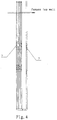
- a tubular cracking furnace for example an ethylene cracking furnace, comprising a convection section and a radiant section or dual radiant sections, an at least one pass radiant tube of metal arranged in said radiant section having at least one member for intensifying heat transfer through the wall of the at least one radiant tube to fluid flowing through that tube in a fluid flow direction, by changing plug flow of the fluid in the at least one radiant tube to turbulence flow, said at least one member comprising a first such member, which is arranged at a location between 10D and 25D upstream, relative to the fluid flow direction, of an extreme point of said at least one pass radiant tube metal temperature, at which extreme point the tube metal temperature is a maximum, wherein D is the inner diameter of said at least one pass radiant tube.
- said at least one member also comprises a second such member, which is arranged downstream of the first such member, with a distance less than Y, being the maximum affected distance of said first such member, defined as the radiant tube distance from the point that materials in the fluid begin flowing through the first such member to the point that the tangential speed of said materials becomes zero again, said distance less than Y being for example arranged between 0.7Y and 1.0Y.
- said at least one heat member comprises a third such member, which is arranged downstream of the second such member, with a distance less than Y, being the maximum affected distance of said second heat transfer intensifying member, defined as the radiant tube distance from the point that materials in the fluid begin flowing through the second such member to the point that the tangential speed of said materials becomes zero again, said distance less than Y being for example arranged between 0.7Y and 1.0Y.
- said at least one member comprises a fourth such member, which is arranged downstream of the third such member, with a distance less than Y, being the maximum affected distance of said third such member, defined as the radiant tube distance from the point that materials in the fluid begin flowing through the third such member to the point that the tangential speed of said materials becomes zero again, said distance less than Y being for example arranged between 0.7Y and 1.0Y.
- the or each such member is a twisted-tape tube.
- the twist ratio of said twisted-tape tube is between 2 and 3 and the twisted tape has a twisted angle of 180°,
- said Y for the twisted tape tube is between about 50D and 60D.
- said radiant tube is type 2-1 or type 4-1.
- said radiant tube is type 2-1, and said first, second, third and fourth such members are twisted-tape tubes and only arranged in a second pass tube.
- said radiant tube is type 2-1
- said first, second, third and fourth such members are twisted-tape tubes and arranged in first and second pass tubes, respectively.
- said radiant tube is type 4-1, and said first, second, third and fourth such members are twisted-tape tubes and only arranged in a second pass tube.
- said radiant tube is type 4-1, and said first, second, third and fourth such members are twisted-tape tubes and arranged in first and second pass tubes, respectively.
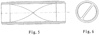
- the heat transfer intensifying members in the present disclosure may use the "twisted-tape tube" in CN1133862C , as shown in fig.5 and 6 .
- the twisted ratio (which is the ratio of the axial length of the twisted-tape tube with a twisted angle 180° vs the inner diameter) is preferably 2 to 3, it is 2.5 in the embodiments.
- the heat transfer intensifying members arranged in the radiant tube could direct the in-process materials flowing forward helically other than straight ahead, so that the in-process materials passing through inside twisted-tape tube strongly flush the inner surface of the twisted-tape tube tangentially. And thereby, the thickness of the boundary layer on the inner surface of twisted-tape tube are destroyed and become much thinner, so that the heat resistance nearby the flowing boundary layer is much smaller. Therefore, the heat transfer efficiency of twisted-tape tube could be increased.
- the in-process materials Before the in-process materials in the radiant tube pass through the surface of twisted-tape tube, the in-process materials flow in plug flow type, the tangential speed of which is almost zero; immediately after the in-process materials flow through twisted-tape tube, the flow type of the in-process materials is changed abruptly, and the tangential speed of the in-process materials increases rapidly. After the in-process materials pass the twisted-tape tube, the tangential speed of the in-process materials is falling off and trending down till zero along the axial direction of the tube.
- maximum affected distance of the twisted-tape tube means the distance of the radiant tube calculated from the point that the in-process materials begin flowing through twisted-tape tube to the point that the tangential speed of the in-process materials becomes zero again.
- the maximum affected distance of the twisted-tape tube with 180° twisted angle is approximately from about 50D to 60D, wherein D is defined as inner diameter of radiant tube.
- the twisted-tape tube in the embodiment uses twisted ratio of 2.5 with a twisted angle of 180°.
- each pass tube have a extreme point, for example as for the radiant tube type 2-1, its first pass tube has one extreme point, and second pass tube also has one extreme point, but the positions of the extreme points in two pass tubes are different. Normally, the positions of the extreme points would be fixed once cracking furnace structure is determined. All the factories using cracking furnace can offer the corresponding positions of the extreme points of the cracking furnace.
- the first twisted-tape tube is arranged at a location between 0 and 40D, preferably between 10 and 25D before the maximum temperature of tube metal temperature at each pass radiant tube;
- the second twisted-tape tube is arranged downstream the first twisted-tape tube, with a distance less than the "maximum affected distance Y" of the first one, preferably arranged between 0.7Y and 1.0Y;
- the third twisted-tape tube is arranged downstream the second twisted-tape tube, with a distance less than the "maximum affected distance Y" of the second one, preferably arranged between 0.7Y and 1.0Y; the arrangement of the forth one follows similar rule.
- the location of the last twisted-tape tube at each pass should not be less than 40D away from each pass tube end to meet mechanical strength requirement.
- the twisted-tape tube might also be arranged before the first twisted-tape tube.
- the distance between this twisted-tape tube and the first twisted-tape tube should be less than the "maximum affected distance Y" of this twisted-tape tube, preferably arranged between 0.7Y and Y. If the radiant tube has several passes, each pass tube should follow same rule within each pass. However, the exact position of twisted-tape tube does not necessarily be the same.
- the total number of the twisted-tape tubes should still be determined with other parameters, for instance, especially pressure drop.
- twisted-tape tubes are put on the most efficient points in cracking furnace. However it does not necessarily mean that all these points have to be arranged with twisted-tape tube, and also it does not necessarily mean that twisted-tape tubes could not be installed on other locations.
- An ethylene cracking furnace using two pass radiant tubes type 2-1 (see fig.1 ), which comprises: a high pressure steam drum 1, a convection section 2, radiant tubes 3, burners 4, a radiant section 5, a quenching boiler 6. It has a yield of ethylene of 100 kilo-ton per year.
- the cracking material uses naphtha.
- the number of twisted-tape tubes to be arranged is determined.
- Two heat transfer intensifying members 7 were arranged in each pass radiant tube, that is to say, each group of the radiant tube is totally provided with six heat transfer intensifying members 7 (see fig.2 ), wherein the heat transfer intensifying member is the twisted-tape tube.(see fig.5 ).
- Tablet 1 different locations of the twisted-tape tube of each project The location of twisted-tape tube in the first pass The location of twisted-tape tube in the second pass upstream of the maximum temperature of TMT downstream of the maximum temperature of TMT upstream of the maximum temperature of TMT downstream of the maximum temperature of TMT Project A 25 30 25 30 Project B 45 10 45 10 Project C 40 15 40 15 Project D 35 20 35 20 Project E 30 25 30 25 Project F 20 35 20 35 Project G 15 40 15 40 Project H 10 45 10 45 Project I 5 50 5 50
- Tablet 2 contrasts of all kinds of projects Project A Project B Project C SOR EOR SOR EOR SOR EOR EOR EOR Feed rate (T/h) 41.2 41.2 41.2 41.2 41.2 steam to oil ratio 0.5 0.5 0.5 0.5 0.5 0.5 COT(coil outlet temperature) ( ⁇ ) 830 830 830 830 830 830 Impact on run length TMT TMT TMT Run length(day) 56 41 44 Tablet 3 contrasts of all kinds of projects Project D Project E Project F SOR EOR SOR EOR EOR EOR EOR EOR EOR EOR EOR EOR EOR EOR Feed rate (T/h) 41.2 41.2 41.2 41.2 steam to oil ratio 0.5 0.5 0.5 0.5 0.5 COT(coil outlet temperature) ( ⁇ ) 830 830 830 830 830 830 830 830 830 Impact on run length TMT TMT TMT run length (day) 46 48 54 Tablet 4 contrasts of all kinds of projects Project G Project H Project I SOR EOR EOR EOR EOR EOR Fee
- An ethylene cracking furnace using two pass radiant tubes type 4-1 (see fig,1 ), which comprises: a high pressure steam drum 1, a convection section 2, a radiant tube 3, burners 4, a radiant section 5, a quenching boiler 6. It has a yield of ethylene of 100 kilo-ton per year.
- the radiant tube 3 of this example is two pass radiant tube type 4-1.
- the cracking material uses naphtha.
- the number of twisted-tape tubes to be arranged is determined.
- Two heat transfer intensifying members 7 are arranged in each pass radiant tube, that is to say, each group of the radiant tubes is totally provided with ten heat transfer intensifying members 7(see fig.2 ), wherein the heat transfer intensifying member is the twisted-tape tube (see fig.5 ).
- Tablet 5 different locations of the twisted-tape tubes of each project The location of twisted-tape tube in the first pass The location of twisted-tape tube in the second pass upstream of the maximum temperature of TMT downstream of the maximum temperature of TMT upstream of the maximum temperature of TMT downstream of the maximum temperature of TMT Project A 25 30 25 30 Project B 45 10 45 10 Project C 40 15 40 15 Project D 35 20 35 20 Project E 30 25 30 25 Project F 20 35 20 35 Project G 15 40 15 40 Project H 10 45 10 45 Project I 5 50 5 50
- An ethylene cracking furnace using two pass radiant tubes type 2-1 (see fig.1 ), which comprises a high pressure steam drum 1, a convection section 2, a radiant tube 3, burners 4, a radiant section 5, a quenching boiler 6. It has a yield of ethylene of 60 kilo-ton per year.
- the cracking material uses naphtha.
- the number of twisted-tape tubes to be arranged is determined.
- Two heat transfer intensifying members 7 are arranged in each pass radiant tube, that is to say, each group of the radiant tubes is totally provided with six heat transfer intensifying members 7 (see fig.2 ), wherein the heat transfer intensifying member is the twisted-tape tube (see fig.5 ).
- An ethylene cracking furnace using two pass radiant tubes type 2-1 (see fig.1 ), which comprises a high pressure steam drum 1, a convection section 2, a radiant tube 3, burners 4, a radiant section 5, a quenching boiler 6, of which the radiant tube includes 48 groups of type 2-1 tubes. It has the yield of ethylene of 100 kilo-ton ethylene per year, The cracking material uses naphtha.
- heat transfer intensifying members 7 are arranged in radiant tube 3 along the fluid flowing direction, wherein the heat transfer intensifying member is the twisted-tape tube as shown in fig.5 .
- a twisted-tape tube is arranged at a location which is 25 times the first pass radiant tube diameter D upstream of the extreme point of the first pass radiant tube metal temperature. Another twisted-tape tube is arranged at a location which is 30 D downstream of the extreme point of the first pass radiant tube metal temperature.
- a twisted-tape tube is arranged at a location which is 25 times the second pass radiant tube diameter D upstream of the extreme point of the second pass radiant tube metal temperature.
- Another twisted-tape tube is arranged at a location which is 30 D downstream of the extreme point of the second pass radiant tube metal temperature.
Landscapes
- Engineering & Computer Science (AREA)
- Physics & Mathematics (AREA)
- Thermal Sciences (AREA)
- Mechanical Engineering (AREA)
- General Engineering & Computer Science (AREA)
- Chemical & Material Sciences (AREA)
- Geometry (AREA)
- Oil, Petroleum & Natural Gas (AREA)
- Chemical Kinetics & Catalysis (AREA)
- General Chemical & Material Sciences (AREA)
- Organic Chemistry (AREA)
- Production Of Liquid Hydrocarbon Mixture For Refining Petroleum (AREA)
- Tunnel Furnaces (AREA)
Priority Applications (1)
| Application Number | Priority Date | Filing Date | Title |
|---|---|---|---|
| PL08715068T PL2133644T3 (pl) | 2007-03-28 | 2008-03-28 | Piec typu rurowego do krakowania |
Applications Claiming Priority (2)
| Application Number | Priority Date | Filing Date | Title |
|---|---|---|---|
| CN200710064886 | 2007-03-28 | ||
| PCT/CN2008/000626 WO2008116397A1 (en) | 2007-03-28 | 2008-03-28 | A tube type cracking furnace |
Publications (3)
| Publication Number | Publication Date |
|---|---|
| EP2133644A1 EP2133644A1 (en) | 2009-12-16 |
| EP2133644A4 EP2133644A4 (en) | 2011-08-03 |
| EP2133644B1 true EP2133644B1 (en) | 2019-08-07 |
Family
ID=39788049
Family Applications (1)
| Application Number | Title | Priority Date | Filing Date |
|---|---|---|---|
| EP08715068.6A Active EP2133644B1 (en) | 2007-03-28 | 2008-03-28 | A tube type cracking furnace |
Country Status (9)
| Country | Link |
|---|---|
| US (1) | US8585890B2 (pl) |
| EP (1) | EP2133644B1 (pl) |
| KR (1) | KR101422879B1 (pl) |
| BR (1) | BRPI0812274B1 (pl) |
| CA (1) | CA2681281C (pl) |
| MY (1) | MY151164A (pl) |
| PL (1) | PL2133644T3 (pl) |
| RU (1) | RU2453580C2 (pl) |
| WO (1) | WO2008116397A1 (pl) |
Families Citing this family (5)
| Publication number | Priority date | Publication date | Assignee | Title |
|---|---|---|---|---|
| CN101723784B (zh) * | 2008-10-16 | 2012-12-26 | 中国石油化工股份有限公司 | 一种乙烯裂解炉 |
| AR081445A1 (es) * | 2010-02-08 | 2012-09-05 | Lummus Technology Inc | Un metodo para producir un dispositivo intercambiador de calor que tiene por lo menos un tubo para el intercambio de calor, metodo para modificar un dispositivo intercambiador de calor, dispositivo intercambiador de calor y proceso para producir olefina |
| CN103791753B (zh) * | 2012-10-30 | 2016-09-21 | 中国石油化工股份有限公司 | 一种传热管 |
| CN103791483B (zh) * | 2012-10-30 | 2020-02-18 | 中国石油化工股份有限公司 | 苯乙烯加热炉及其在化工领域的应用 |
| CN104560111B (zh) * | 2013-10-25 | 2017-08-25 | 中国石油化工股份有限公司 | 传热管以及使用其的裂解炉 |
Family Cites Families (20)
| Publication number | Priority date | Publication date | Assignee | Title |
|---|---|---|---|---|
| FR2436959A1 (fr) * | 1978-09-19 | 1980-04-18 | Ferodo Sa | Perfectionnements apportes aux echangeurs de chaleur tubulaires et aux agitateurs destines a de tels echangeurs |
| DE2854061C2 (de) * | 1978-12-14 | 1987-04-02 | Linde Ag, 6200 Wiesbaden | Verfahren zum Vorwärmen von Kohlenwasserstoffen vor deren thermischer Spaltung sowie Spaltofen zur Durchführung des Verfahrens |
| SU1390511A1 (ru) * | 1985-10-18 | 1988-04-23 | МВТУ им.Н.Э.Баумана | Пучок теплообменных труб |
| JPH063075A (ja) | 1992-06-18 | 1994-01-11 | Rinnai Corp | 液液熱交換器 |
| DE9210427U1 (de) | 1992-08-04 | 1992-09-24 | Graf, Josef, 8201 Frasdorf | Luftmatratze mit einem als Pumpe wirkenden Teil |
| RU2048663C1 (ru) * | 1992-09-21 | 1995-11-20 | Технологический институт Саратовского государственного технического университета | Трубчатая печь |
| JP3001181B2 (ja) * | 1994-07-11 | 2000-01-24 | 株式会社クボタ | エチレン製造用反応管 |
| DE4444472A1 (de) | 1994-12-14 | 1996-06-20 | Hoechst Ag | Verfahren zur Herstellung von Triphenylmethanfarbmitteln |
| JP2000146482A (ja) * | 1998-09-16 | 2000-05-26 | China Petrochem Corp | 熱交換器チュ―ブ、その製造方法、及びその熱交換器チュ―ブを用いるクラッキング炉又は他の管状加熱炉 |
| CN1133862C (zh) | 1998-09-16 | 2004-01-07 | 中国石油化工集团公司 | 一种热交换管及其制造方法和应用 |
| US6484795B1 (en) * | 1999-09-10 | 2002-11-26 | Martin R. Kasprzyk | Insert for a radiant tube |
| US7004085B2 (en) * | 2002-04-10 | 2006-02-28 | Abb Lummus Global Inc. | Cracking furnace with more uniform heating |
| PT1845327E (pt) * | 2002-06-10 | 2008-12-22 | Wolverine Tube Inc | Método de fabrico de um tubo de transferência de calor |
| US20050131263A1 (en) * | 2002-07-25 | 2005-06-16 | Schmidt + Clemens Gmbh + Co. Kg, | Process and finned tube for the thermal cracking of hydrocarbons |
| CN100342199C (zh) * | 2002-11-15 | 2007-10-10 | 株式会社久保田 | 具有螺旋翅片的裂化管 |
| EP1561796A1 (en) * | 2004-02-05 | 2005-08-10 | Technip France | Cracking furnace |
| US7128139B2 (en) * | 2004-10-14 | 2006-10-31 | Nova Chemicals (International) S.A. | External ribbed furnace tubes |
| CN100338182C (zh) | 2004-10-29 | 2007-09-19 | 中国石油化工股份有限公司 | 一种单程变径炉管的裂解炉 |
| CN101133862A (zh) | 2006-08-31 | 2008-03-05 | 天津中英纳米科技发展有限公司 | 一种强化肉酱制品及其制备方法 |
| CN101093250A (zh) | 2007-07-20 | 2007-12-26 | 太原市优特奥科电子科技有限公司 | 高压电流互感器计量误差实时在线监测方法及监测装置 |
-
2008
- 2008-03-28 PL PL08715068T patent/PL2133644T3/pl unknown
- 2008-03-28 US US12/593,216 patent/US8585890B2/en active Active
- 2008-03-28 WO PCT/CN2008/000626 patent/WO2008116397A1/zh not_active Ceased
- 2008-03-28 BR BRPI0812274-1A patent/BRPI0812274B1/pt active IP Right Grant
- 2008-03-28 KR KR1020097019550A patent/KR101422879B1/ko active Active
- 2008-03-28 MY MYPI20094013 patent/MY151164A/en unknown
- 2008-03-28 CA CA2681281A patent/CA2681281C/en active Active
- 2008-03-28 EP EP08715068.6A patent/EP2133644B1/en active Active
- 2008-03-28 RU RU2009139458/06A patent/RU2453580C2/ru active
Non-Patent Citations (1)
| Title |
|---|
| None * |
Also Published As
| Publication number | Publication date |
|---|---|
| PL2133644T3 (pl) | 2020-02-28 |
| BRPI0812274B1 (pt) | 2021-04-27 |
| US8585890B2 (en) | 2013-11-19 |
| WO2008116397A1 (en) | 2008-10-02 |
| US20100147672A1 (en) | 2010-06-17 |
| CA2681281C (en) | 2016-02-09 |
| KR101422879B1 (ko) | 2014-07-23 |
| EP2133644A1 (en) | 2009-12-16 |
| EP2133644A4 (en) | 2011-08-03 |
| BRPI0812274A2 (pt) | 2020-05-12 |
| MY151164A (en) | 2014-04-30 |
| RU2453580C2 (ru) | 2012-06-20 |
| RU2009139458A (ru) | 2011-05-10 |
| CA2681281A1 (en) | 2008-03-28 |
| KR20100014478A (ko) | 2010-02-10 |
Similar Documents
| Publication | Publication Date | Title |
|---|---|---|
| EP2082796B1 (en) | Olefin production furnace with a helical tube | |
| EP2133644B1 (en) | A tube type cracking furnace | |
| CN1195823C (zh) | 带有内部有翼片的u形辐射线圈的高温分解炉 | |
| JP5020640B2 (ja) | 分解炉 | |
| US7758823B2 (en) | Quench exchange with extended surface on process side | |
| US6852294B2 (en) | Alternate coke furnace tube arrangement | |
| EP0523762B1 (en) | Thermal cracking furnace and process | |
| EP2328851B1 (en) | Pyrolysis furnace with helical tube | |
| CN109477004B (zh) | 裂解炉 | |
| US8916030B2 (en) | Ethylene cracking furnace | |
| KR101599662B1 (ko) | 열 교환 장치 및 그 제조방법 | |
| EP2248581A1 (en) | Process for quenching the effluent gas of a furnace | |
| KR101857885B1 (ko) | 파이어 히터 | |
| US20160334135A1 (en) | Double fired u-tube fired heater | |
| MXPA06008885A (en) | Cracking furnace |
Legal Events
| Date | Code | Title | Description |
|---|---|---|---|
| PUAI | Public reference made under article 153(3) epc to a published international application that has entered the european phase |
Free format text: ORIGINAL CODE: 0009012 |
|
| 17P | Request for examination filed |
Effective date: 20090924 |
|
| AK | Designated contracting states |
Kind code of ref document: A1 Designated state(s): AT BE BG CH CY CZ DE DK EE ES FI FR GB GR HR HU IE IS IT LI LT LU LV MC MT NL NO PL PT RO SE SI SK TR |
|
| DAX | Request for extension of the european patent (deleted) | ||
| A4 | Supplementary search report drawn up and despatched |
Effective date: 20110706 |
|
| RIC1 | Information provided on ipc code assigned before grant |
Ipc: F28F 13/12 20060101AFI20110630BHEP Ipc: C10G 9/20 20060101ALI20110630BHEP |
|
| 17Q | First examination report despatched |
Effective date: 20120608 |
|
| STAA | Information on the status of an ep patent application or granted ep patent |
Free format text: STATUS: EXAMINATION IS IN PROGRESS |
|
| RIC1 | Information provided on ipc code assigned before grant |
Ipc: F28F 13/12 20060101AFI20190205BHEP Ipc: F28D 21/00 20060101ALI20190205BHEP Ipc: C10G 9/20 20060101ALI20190205BHEP Ipc: F28F 1/40 20060101ALI20190205BHEP Ipc: F28F 19/00 20060101ALI20190205BHEP |
|
| GRAP | Despatch of communication of intention to grant a patent |
Free format text: ORIGINAL CODE: EPIDOSNIGR1 |
|
| STAA | Information on the status of an ep patent application or granted ep patent |
Free format text: STATUS: GRANT OF PATENT IS INTENDED |
|
| INTG | Intention to grant announced |
Effective date: 20190321 |
|
| GRAS | Grant fee paid |
Free format text: ORIGINAL CODE: EPIDOSNIGR3 |
|
| GRAA | (expected) grant |
Free format text: ORIGINAL CODE: 0009210 |
|
| STAA | Information on the status of an ep patent application or granted ep patent |
Free format text: STATUS: THE PATENT HAS BEEN GRANTED |
|
| AK | Designated contracting states |
Kind code of ref document: B1 Designated state(s): AT BE BG CH CY CZ DE DK EE ES FI FR GB GR HR HU IE IS IT LI LT LU LV MC MT NL NO PL PT RO SE SI SK TR |
|
| REG | Reference to a national code |
Ref country code: GB Ref legal event code: FG4D |
|
| REG | Reference to a national code |
Ref country code: CH Ref legal event code: EP Ref country code: AT Ref legal event code: REF Ref document number: 1164536 Country of ref document: AT Kind code of ref document: T Effective date: 20190815 |
|
| REG | Reference to a national code |
Ref country code: DE Ref legal event code: R096 Ref document number: 602008060830 Country of ref document: DE |
|
| REG | Reference to a national code |
Ref country code: IE Ref legal event code: FG4D |
|
| REG | Reference to a national code |
Ref country code: NL Ref legal event code: FP |
|
| REG | Reference to a national code |
Ref country code: LT Ref legal event code: MG4D |
|
| PG25 | Lapsed in a contracting state [announced via postgrant information from national office to epo] |
Ref country code: PT Free format text: LAPSE BECAUSE OF FAILURE TO SUBMIT A TRANSLATION OF THE DESCRIPTION OR TO PAY THE FEE WITHIN THE PRESCRIBED TIME-LIMIT Effective date: 20191209 Ref country code: NO Free format text: LAPSE BECAUSE OF FAILURE TO SUBMIT A TRANSLATION OF THE DESCRIPTION OR TO PAY THE FEE WITHIN THE PRESCRIBED TIME-LIMIT Effective date: 20191107 Ref country code: SE Free format text: LAPSE BECAUSE OF FAILURE TO SUBMIT A TRANSLATION OF THE DESCRIPTION OR TO PAY THE FEE WITHIN THE PRESCRIBED TIME-LIMIT Effective date: 20190807 Ref country code: FI Free format text: LAPSE BECAUSE OF FAILURE TO SUBMIT A TRANSLATION OF THE DESCRIPTION OR TO PAY THE FEE WITHIN THE PRESCRIBED TIME-LIMIT Effective date: 20190807 Ref country code: HR Free format text: LAPSE BECAUSE OF FAILURE TO SUBMIT A TRANSLATION OF THE DESCRIPTION OR TO PAY THE FEE WITHIN THE PRESCRIBED TIME-LIMIT Effective date: 20190807 Ref country code: LT Free format text: LAPSE BECAUSE OF FAILURE TO SUBMIT A TRANSLATION OF THE DESCRIPTION OR TO PAY THE FEE WITHIN THE PRESCRIBED TIME-LIMIT Effective date: 20190807 Ref country code: BG Free format text: LAPSE BECAUSE OF FAILURE TO SUBMIT A TRANSLATION OF THE DESCRIPTION OR TO PAY THE FEE WITHIN THE PRESCRIBED TIME-LIMIT Effective date: 20191107 |
|
| REG | Reference to a national code |
Ref country code: AT Ref legal event code: MK05 Ref document number: 1164536 Country of ref document: AT Kind code of ref document: T Effective date: 20190807 |
|
| PG25 | Lapsed in a contracting state [announced via postgrant information from national office to epo] |
Ref country code: ES Free format text: LAPSE BECAUSE OF FAILURE TO SUBMIT A TRANSLATION OF THE DESCRIPTION OR TO PAY THE FEE WITHIN THE PRESCRIBED TIME-LIMIT Effective date: 20190807 Ref country code: GR Free format text: LAPSE BECAUSE OF FAILURE TO SUBMIT A TRANSLATION OF THE DESCRIPTION OR TO PAY THE FEE WITHIN THE PRESCRIBED TIME-LIMIT Effective date: 20191108 Ref country code: LV Free format text: LAPSE BECAUSE OF FAILURE TO SUBMIT A TRANSLATION OF THE DESCRIPTION OR TO PAY THE FEE WITHIN THE PRESCRIBED TIME-LIMIT Effective date: 20190807 Ref country code: IS Free format text: LAPSE BECAUSE OF FAILURE TO SUBMIT A TRANSLATION OF THE DESCRIPTION OR TO PAY THE FEE WITHIN THE PRESCRIBED TIME-LIMIT Effective date: 20191207 |
|
| PG25 | Lapsed in a contracting state [announced via postgrant information from national office to epo] |
Ref country code: TR Free format text: LAPSE BECAUSE OF FAILURE TO SUBMIT A TRANSLATION OF THE DESCRIPTION OR TO PAY THE FEE WITHIN THE PRESCRIBED TIME-LIMIT Effective date: 20190807 |
|
| PG25 | Lapsed in a contracting state [announced via postgrant information from national office to epo] |
Ref country code: RO Free format text: LAPSE BECAUSE OF FAILURE TO SUBMIT A TRANSLATION OF THE DESCRIPTION OR TO PAY THE FEE WITHIN THE PRESCRIBED TIME-LIMIT Effective date: 20190807 Ref country code: EE Free format text: LAPSE BECAUSE OF FAILURE TO SUBMIT A TRANSLATION OF THE DESCRIPTION OR TO PAY THE FEE WITHIN THE PRESCRIBED TIME-LIMIT Effective date: 20190807 Ref country code: AT Free format text: LAPSE BECAUSE OF FAILURE TO SUBMIT A TRANSLATION OF THE DESCRIPTION OR TO PAY THE FEE WITHIN THE PRESCRIBED TIME-LIMIT Effective date: 20190807 Ref country code: IT Free format text: LAPSE BECAUSE OF FAILURE TO SUBMIT A TRANSLATION OF THE DESCRIPTION OR TO PAY THE FEE WITHIN THE PRESCRIBED TIME-LIMIT Effective date: 20190807 Ref country code: DK Free format text: LAPSE BECAUSE OF FAILURE TO SUBMIT A TRANSLATION OF THE DESCRIPTION OR TO PAY THE FEE WITHIN THE PRESCRIBED TIME-LIMIT Effective date: 20190807 |
|
| PG25 | Lapsed in a contracting state [announced via postgrant information from national office to epo] |
Ref country code: CZ Free format text: LAPSE BECAUSE OF FAILURE TO SUBMIT A TRANSLATION OF THE DESCRIPTION OR TO PAY THE FEE WITHIN THE PRESCRIBED TIME-LIMIT Effective date: 20190807 Ref country code: IS Free format text: LAPSE BECAUSE OF FAILURE TO SUBMIT A TRANSLATION OF THE DESCRIPTION OR TO PAY THE FEE WITHIN THE PRESCRIBED TIME-LIMIT Effective date: 20200224 Ref country code: SK Free format text: LAPSE BECAUSE OF FAILURE TO SUBMIT A TRANSLATION OF THE DESCRIPTION OR TO PAY THE FEE WITHIN THE PRESCRIBED TIME-LIMIT Effective date: 20190807 |
|
| REG | Reference to a national code |
Ref country code: DE Ref legal event code: R097 Ref document number: 602008060830 Country of ref document: DE |
|
| PLBE | No opposition filed within time limit |
Free format text: ORIGINAL CODE: 0009261 |
|
| STAA | Information on the status of an ep patent application or granted ep patent |
Free format text: STATUS: NO OPPOSITION FILED WITHIN TIME LIMIT |
|
| PG2D | Information on lapse in contracting state deleted |
Ref country code: IS |
|
| 26N | No opposition filed |
Effective date: 20200603 |
|
| PG25 | Lapsed in a contracting state [announced via postgrant information from national office to epo] |
Ref country code: SI Free format text: LAPSE BECAUSE OF FAILURE TO SUBMIT A TRANSLATION OF THE DESCRIPTION OR TO PAY THE FEE WITHIN THE PRESCRIBED TIME-LIMIT Effective date: 20190807 |
|
| PG25 | Lapsed in a contracting state [announced via postgrant information from national office to epo] |
Ref country code: MC Free format text: LAPSE BECAUSE OF FAILURE TO SUBMIT A TRANSLATION OF THE DESCRIPTION OR TO PAY THE FEE WITHIN THE PRESCRIBED TIME-LIMIT Effective date: 20190807 |
|
| REG | Reference to a national code |
Ref country code: CH Ref legal event code: PL |
|
| PG25 | Lapsed in a contracting state [announced via postgrant information from national office to epo] |
Ref country code: LU Free format text: LAPSE BECAUSE OF NON-PAYMENT OF DUE FEES Effective date: 20200328 |
|
| PG25 | Lapsed in a contracting state [announced via postgrant information from national office to epo] |
Ref country code: IE Free format text: LAPSE BECAUSE OF NON-PAYMENT OF DUE FEES Effective date: 20200328 Ref country code: LI Free format text: LAPSE BECAUSE OF NON-PAYMENT OF DUE FEES Effective date: 20200331 Ref country code: CH Free format text: LAPSE BECAUSE OF NON-PAYMENT OF DUE FEES Effective date: 20200331 |
|
| PG25 | Lapsed in a contracting state [announced via postgrant information from national office to epo] |
Ref country code: MT Free format text: LAPSE BECAUSE OF FAILURE TO SUBMIT A TRANSLATION OF THE DESCRIPTION OR TO PAY THE FEE WITHIN THE PRESCRIBED TIME-LIMIT Effective date: 20190807 Ref country code: CY Free format text: LAPSE BECAUSE OF FAILURE TO SUBMIT A TRANSLATION OF THE DESCRIPTION OR TO PAY THE FEE WITHIN THE PRESCRIBED TIME-LIMIT Effective date: 20190807 |
|
| P01 | Opt-out of the competence of the unified patent court (upc) registered |
Effective date: 20230502 |
|
| PGFP | Annual fee paid to national office [announced via postgrant information from national office to epo] |
Ref country code: DE Payment date: 20250218 Year of fee payment: 18 |
|
| PGFP | Annual fee paid to national office [announced via postgrant information from national office to epo] |
Ref country code: BE Payment date: 20250227 Year of fee payment: 18 |
|
| PGFP | Annual fee paid to national office [announced via postgrant information from national office to epo] |
Ref country code: FR Payment date: 20250325 Year of fee payment: 18 Ref country code: PL Payment date: 20250228 Year of fee payment: 18 |
|
| PGFP | Annual fee paid to national office [announced via postgrant information from national office to epo] |
Ref country code: GB Payment date: 20250220 Year of fee payment: 18 |
|
| PGFP | Annual fee paid to national office [announced via postgrant information from national office to epo] |
Ref country code: NL Payment date: 20260227 Year of fee payment: 19 |