EP2133205A1 - Fluid discharge device, control method for a fluid discharge device, and fluid tank - Google Patents
Fluid discharge device, control method for a fluid discharge device, and fluid tank Download PDFInfo
- Publication number
- EP2133205A1 EP2133205A1 EP09007616A EP09007616A EP2133205A1 EP 2133205 A1 EP2133205 A1 EP 2133205A1 EP 09007616 A EP09007616 A EP 09007616A EP 09007616 A EP09007616 A EP 09007616A EP 2133205 A1 EP2133205 A1 EP 2133205A1
- Authority
- EP
- European Patent Office
- Prior art keywords
- fluid
- ink
- fluid tank
- tank
- discharge device
- Prior art date
- Legal status (The legal status is an assumption and is not a legal conclusion. Google has not performed a legal analysis and makes no representation as to the accuracy of the status listed.)
- Granted
Links
Images


Classifications
-
- B—PERFORMING OPERATIONS; TRANSPORTING
- B41—PRINTING; LINING MACHINES; TYPEWRITERS; STAMPS
- B41J—TYPEWRITERS; SELECTIVE PRINTING MECHANISMS, i.e. MECHANISMS PRINTING OTHERWISE THAN FROM A FORME; CORRECTION OF TYPOGRAPHICAL ERRORS
- B41J2/00—Typewriters or selective printing mechanisms characterised by the printing or marking process for which they are designed
- B41J2/005—Typewriters or selective printing mechanisms characterised by the printing or marking process for which they are designed characterised by bringing liquid or particles selectively into contact with a printing material
- B41J2/01—Ink jet
- B41J2/17—Ink jet characterised by ink handling
- B41J2/175—Ink supply systems ; Circuit parts therefor
- B41J2/17503—Ink cartridges
- B41J2/17543—Cartridge presence detection or type identification
- B41J2/17546—Cartridge presence detection or type identification electronically
-
- B—PERFORMING OPERATIONS; TRANSPORTING
- B41—PRINTING; LINING MACHINES; TYPEWRITERS; STAMPS
- B41J—TYPEWRITERS; SELECTIVE PRINTING MECHANISMS, i.e. MECHANISMS PRINTING OTHERWISE THAN FROM A FORME; CORRECTION OF TYPOGRAPHICAL ERRORS
- B41J15/00—Devices or arrangements of selective printing mechanisms, e.g. ink-jet printers or thermal printers, specially adapted for supporting or handling copy material in continuous form, e.g. webs
- B41J15/04—Supporting, feeding, or guiding devices; Mountings for web rolls or spindles
- B41J15/042—Supporting, feeding, or guiding devices; Mountings for web rolls or spindles for loading rolled-up continuous copy material into printers, e.g. for replacing a used-up paper roll; Point-of-sale printers with openable casings allowing access to the rolled-up continuous copy material
-
- B—PERFORMING OPERATIONS; TRANSPORTING
- B41—PRINTING; LINING MACHINES; TYPEWRITERS; STAMPS
- B41J—TYPEWRITERS; SELECTIVE PRINTING MECHANISMS, i.e. MECHANISMS PRINTING OTHERWISE THAN FROM A FORME; CORRECTION OF TYPOGRAPHICAL ERRORS
- B41J2/00—Typewriters or selective printing mechanisms characterised by the printing or marking process for which they are designed
- B41J2/005—Typewriters or selective printing mechanisms characterised by the printing or marking process for which they are designed characterised by bringing liquid or particles selectively into contact with a printing material
- B41J2/01—Ink jet
- B41J2/17—Ink jet characterised by ink handling
- B41J2/175—Ink supply systems ; Circuit parts therefor
- B41J2/17503—Ink cartridges
- B41J2/17506—Refilling of the cartridge
- B41J2/17509—Whilst mounted in the printer
-
- B—PERFORMING OPERATIONS; TRANSPORTING
- B41—PRINTING; LINING MACHINES; TYPEWRITERS; STAMPS
- B41J—TYPEWRITERS; SELECTIVE PRINTING MECHANISMS, i.e. MECHANISMS PRINTING OTHERWISE THAN FROM A FORME; CORRECTION OF TYPOGRAPHICAL ERRORS
- B41J3/00—Typewriters or selective printing or marking mechanisms characterised by the purpose for which they are constructed
- B41J3/407—Typewriters or selective printing or marking mechanisms characterised by the purpose for which they are constructed for marking on special material
- B41J3/4073—Printing on three-dimensional objects not being in sheet or web form, e.g. spherical or cubic objects
Definitions
- the present invention relates to a fluid discharge device that supplies fluid from a removable fluid tank to a head from which the fluid is discharged, to a control method for the fluid discharge device, and to a fluid tank.
- a common type of fluid discharge device is an inkjet printer that supplies ink from a removable ink cartridge to a recording head, and discharges the ink from the recording head to print on paper.
- This device enables confirming from the label on the removed ink cartridge whether or not the ink cartridge can be used, but because a reading sensor and a writing device are needed to read and write information on the trademark logo or number-of-uses label, the parts count increases and the construction becomes more complicated, leading to a higher product cost.
- the ink information cannot be read accurately by the reading sensor, and the printing process may be needlessly interrupted.
- the fluid discharge device can both store the fluid usage history of fluid in the fluid tank to a storage unit and record the fluid usage history information on an outside surface of the fluid tank by the head.
- the user can easily visually confirm the fluid usage history information, such as how much fluid is left, from the fluid tank after the fluid tank has been removed from the loading unit.
- the fluid usage history information can be acquired by reading the fluid usage history information stored in the storage unit using the reading/writing unit.
- the fluid tank container and internal fluid packs do not need to be transparent, and fluid deterioration resulting from using transparent materials is prevented.
- the fluid tank loaded in the loading unit has on a side facing the head a label that can be printed by the head, thereby enabling reusing the housing of the fluid tank by simply peeling the label off and applying a new label.
- the controller preferably records the fluid usage history information on the fluid tank synchronized to the write timing of the fluid usage history information to the storage unit.
- controller of the fluid discharge device records the fluid usage history information on the fluid tank synchronized to the write timing of the fluid usage history information to the storage unit, the fluid usage history information written in the storage unit and the fluid usage history information recorded on the outside of the fluid tank housing match.
- a part of the outside surface of the housing of the fluid tank loaded in the loading unit is disposed flush to the discharge surface of the medium to which the head discharges fluid.
- This embodiment allows easy recording of the fluid usage history information on the outside of the fluid tank housing by the head by moving the head from the area for discharging fluid to the medium to the fluid tank side.
- Another aspect of the invention is a fluid tank that has fluid inside and is suitable for use in the fluid discharge device, the fluid tank having a protruding part that protrudes from a part of the fluid tank housing, and, on the distal surface of the protruding part, a printable part that can be printed.
- the printable part of the fluid tank protrudes, the information printed in the printable part is easy to read and the information is easy to confirm.
- the stepped shape means that the fluid tank will be tilted and the chance of the fluid tank resting on the protruding unit is even less. Dust, particulate, and other foreign matter will therefore not stick to the printable part when set down and the quality of printing to the printable area will not drop.
- the printable part can be printed on using the fluid, there is no need to provide a special fluid for printing on the printable part.
- a storage unit that stores data used for detecting a remaining fluid amount is disposed at a position on the housing away from the printable part, thus reducing contamination from printing and thus reducing read/write errors.
- the storage unit is disposed on the surface from which the protruding part protrudes so that if the fluid tank is placed with the printable part side down, the protruding part will prevent the surface on which the storage unit is disposed from contacting the surface on which the fluid tank rests.
- the fluid tank has a basically rectangular box shape, and the protruding part is disposed on a surface with the least area. This configuration further reduces the possibility of contact with the surface on which the fluid tank is placed.
- FIG. 1 to FIG. 5 describe an inkjet printer as an example of a fluid discharge device according to a preferred embodiment of the invention.
- the inkjet printer 1 shown in FIG. 1 is a color printer that prints on recording paper delivered from a paper roll using a plurality of color inks (four inks, black, cyan, magenta, and yellow in this embodiment of the invention).
- a cover 5 is disposed to open and close freely at the front of the printer case 2 that houses the printer.
- a power switch 3, a paper feed switch, and indicators are also disposed on the front of the printer case 2.
- opening the cover 5 opens a paper storage unit 13 that holds the paper roll 11, which is the recording paper 12 used as the print medium wound into a roll, so that the paper roll 11 can be loaded or unloaded, i.e., replaced.
- an ink cartridge 17 in this case, can be inserted to a (cartridge) loading unit 15 in the direction of arrow A, and can be removed by moving the ink cartridge 17 in the opposite direction.
- a carriage 23 on which a head, an inkjet head 21 in this case, is mounted is disposed above the paper storage unit 13 inside the printer case 2.
- the carriage 23 is supported to be freely movable across the width of the paper on a guide member 25 that extends widthwise to the paper roll 11, and can be moved bidirectionally above a platen 28 across the width of the paper roll 11 by an endless belt (not shown in the figure) extending widthwise to the paper roll 11 and a carriage motor 26 that drives the endless belt.
- the inkjet head 21 discharges ink to print on the recording paper 12 delivered from the paper roll 11.
- the standby position (home position) of the bidirectionally movable carriage 23 is on the side of the paper roll 11 opposite to the cartridge loading unit 15.
- a waste ink vacuum mechanism 29 for vacuuming and disposing of ink inside the ink nozzles of the inkjet head 21 exposed from the bottom of the carriage 23 is disposed below the standby position.
- the ink cartridge 17 stores a plurality of color ink packs, not shown, inside the cartridge case 18 that forms the housing of the fluid tank in this example of an inkjet printer.
- Each of the ink packs inside the ink cartridge 17 is made of a flexible material and is sealed with ink stored inside.
- a respective ink supply needle, not shown, disposed on the cartridge loading unit 15 side is inserted to and connects with an ink supply opening of each ink pack.
- This ink supply openings are formed on the surface of the ink cartridge 17 on the insertion side when the ink cartridge 17 is inserted in the direction of arrow A.
- An ink path 31 fixed inside the printer case 2 is connected to the ink supply needles of the cartridge loading unit 15, and one end of a flexible ink supply tube 33 having a respective channel for each color is connected to the ink path 31.
- the other end of the ink supply tube 33 is connected to ink pump units 34, of which for each color (channel) a respective one is disposed on the carriage 23.
- ink pump units 34 are disposed above the inkjet head 21, and connected to a respective self-sealing unit 36 connected to the inkjet head 21.
- the ink pump units 34 and the self-sealing units 36 are disposed in unison with the carriage 23.
- ink from each ink pack inside the ink cartridge 17 is supplied to the ink nozzles of the inkjet head 21 from the respective ink supply needle of the cartridge loading unit 15 through the ink path 31, the respective channel of the ink supply tube 33, the ink pump unit 34 for the respective color, and the self-sealing unit 36 for the respective color.
- the ink pump units 34 pull ink from the ink cartridge 17 by means of a regulator panel 37 that causes the ink pump units 34 to operate by means of the force of carriage 23 movement.
- the regulator panel 37 is disposed at the front in the direction of carriage 23 movement to the standby position.
- Each ink pump unit 34 has a respective rocker arm 35.
- the rocker arm 35 contacts the regulator panel 37 as a result of the carriage 23 moving to the standby position, the rocker arm 35 rocks and drives an internal pump of the associated ink pump unit 34. This causes the pump to pull ink from the corresponding ink pack in the ink cartridge 17.
- Ink that is vacuumed from the inkjet head 21 by the waste ink vacuum mechanism 29 when the inkjet head 21 is cleaned is returned to the ink cartridge 17 as waste ink and is stored in a waste ink absorber inside the ink cartridge 17.
- a printable part 51 is disposed at part of the outside top surface 19 of the ink cartridge 17 when loaded in the cartridge loading unit 15.
- This printable part 51 may be a printable" label which can be peeled off from fluid tank, or it may be made printable by appropriately providing an ink-absorbing layer.
- the printable part 51 of the ink cartridge 17 is positioned substantially flush with the recording paper 12 on the platen 28, that is, the surface to which the inkjet head 21 prints (discharges fluid).
- carriage 23 can also travel past the printing area of the recording paper 12 to the cartridge loading unit 15 side, and can print on the printable part 51 of the ink cartridge 17 loaded in the cartridge loading unit 15.
- a storage unit 52 such as an IC chip substrate, is disposed on the ink cartridge 17 on a side surface away from the location of the printable part 51.
- An ink usage history including such information as the remaining ink quantity, waste ink quantity, first date of use, and device identification information can be written to and read from the storage unit 52.
- Information about the type of ink, for example, is also stored to the storage unit 52 in addition to the ink usage history.
- the inkjet printer 1 also has a reading/writing unit 61, also referred to as a reader/writer, described below that reads and writes the ink usage history to the storage unit 52 of the ink cartridge 17.
- a reading/writing unit 61 also referred to as a reader/writer, described below that reads and writes the ink usage history to the storage unit 52 of the ink cartridge 17.
- a control unit 60 also referred to as a controller, of the inkjet printer 1 sends control signals to the inkjet head 21 and the carriage motor 26 to control driving the inkjet head 21 and the carriage motor 26 and print on the recording paper 12.
- the reader/writer 61 that reads and writes the ink usage history in the storage unit 52 is connected to the control unit 60, and the control unit 60 accesses the ink usage history in the storage unit 52 through the reader/writer 61.
- step S1 the control unit 60 reads the ink information (ink usage history) stored in the storage unit 52 of the ink cartridge 17 loaded in the cartridge loading unit 15 by the reader/writer 61 (step S2). If the loaded ink cartridge 17 is new, the control unit 60 writes the first date of use and device identification information for the device using the ink cartridge 17 to the storage unit 52.
- ink information ink usage history
- step S3 the control unit 60 determines the remaining ink quantity and waste ink quantity in the ink cartridge 17 7 based on how much ink has been consumed by the printing process and how much ink was vacuumed from the inkjet head 21 by the waste ink vacuum mechanism 29, respectively, and writes the remaining ink quantity and waste ink quantity to the storage unit 52 as ink information (step S4).
- control unit 60 controls the inkjet head 21 and the carriage motor 26 to move the inkjet head 21 past the printing area of the recording paper 12 to a position above the ink cartridge 17, and to print the remaining ink quantity information in the ink information written to the storage unit 52 to the printable part 51 of the ink cartridge 17 by the inkjet head 21 (step S5).
- one method of printing the remaining ink quantity information is to provide a blank rectangular indication bar 51 a in the printable part 51 and then gradually fill the indication bar 51 a from one end according to the remaining ink quantity, and print a message such as INK EMPTY on the printable part 51 when the remaining ink quantity goes to a zero level.
- the remaining ink quantity printed in FIG. 5 corresponds to the lowest one of the levels of the four colors black, cyan, magenta, and yellow, and the ink cartridge 17 is replaced when any one color is depleted.
- the remaining ink quantity can obviously also be printed for each color separately.
- step S6 When the process of printing on the recording paper 12 ends (step S6 returns Yes), the control unit 60 also ends the ink information processing.
- the inkjet printer and the control method for the same described in the foregoing embodiment can both store the ink usage history of the ink cartridge 17 in an storage unit 52 and print the information on a printable part 51 on the outside of the ink cartridge 17 by the inkjet head 21 for printing to recording paper 12.
- the user can easily visually confirm ink information, such as how much ink is left from the ink cartridge 17, after the ink cartridge 17 has been removed from the cartridge loading unit 15.
- the ink information can be acquired by reading the ink information stored in the storage unit 52 using the reader/writer 61.
- the ink cartridge 17 container and internal ink packs do not need to be transparent, and ink deterioration resulting from using transparent materials is prevented.
- control unit 60 prints the ink information on the ink cartridge 17 synchronized to the ink information update timing, which is the timing when the ink information is written to the storage unit 52, the ink information written in the storage unit 52 and the ink information printed on the outside of the ink cartridge 17 match.
- the ink information can be easily printed on the outside of the ink cartridge 17 by the inkjet head 21 by moving the inkjet head 21 from the area for printing to the recording paper 12 to the ink cartridge 17 side.
- the storage unit 52 is arranged remote from the printable part 51, there is little soiling of the storage unit 52 by printing to the printable part 51, and read/write errors by the reader/writer 61 are reduced.
- the ink cartridge could be shaped as shown in FIG. 6 .
- FIG. 6 corresponds to FIG. 2 of the foregoing embodiment, and parts with the same or similar function as described in the preceding embodiment are identified using the same reference numerals below.
- this ink cartridge 17a differs from the ink cartridge 17 described above.
- the side where the printable part 51 is disposed is formed as a step projecting above the flat top surface 19b with the printable part 51 disposed to the top protruding surface 19a, and the IC chip substrate (storage unit) 52a is disposed on the top surface 19b at a position away from the printable part 51.
- the ink cartridge 17a has a box-like shape with the surface on the printable part 51 side having two portions 19a and 19b at different levels connected by a step. More specifically, the part where the printable part 51 is disposed is the protruding (at a higher level as seen in Fig. 6 ) surface 19a. Because the printable area is on this protruding surface 19a, the information printed in the printable part 51 is easy to read and the information is easy to confirm. In addition, if the ink cartridge 17a is placed resting on the printable part 51, stability is poor and the ink cartridge 17a easily tips over because this surface is stepped and not flat, and the ink cartridge 17a is therefore unlikely to be placed with the protruding surface 19a down.
- the stepped shape means that the ink cartridge 17a will be tilted and the protruding surface 19a will therefore not be flat against the surface. Dust, particulate, and other foreign matter will therefore not stick to the printable part 51 when set down and the quality of printing to the printable part 51 by the inkjet head 21 will not drop.
- These effects can be further enhanced by reducing the size of the protruding surface 19a.
- the protruding surface 19a is formed on the side of the rectangular printable part 51 with the smallest area.
- the storage unit 52a even if the ink cartridge 17a is placed with the printable part 51 side down, the protruding surface 19a prevents the top surface 19b from touching the surface. Therefore, the storage unit 52a can be protected from dust and other foreign matter on the surface it touches.
- waste ink vacuumed by the waste ink vacuum mechanism 29 is held in a waste ink absorber in the ink cartridge 17, but the waste ink storage unit of the ink cartridge 17 can be formed without the waste ink absorber. In this case there is no need to replace the waste ink absorber when the cartridge is reused, and the cartridge can be reused by simply wiping out the waste ink.
- the surface portion 19a with the printable part 51 of the ink cartridge 17 is disposed flush with the recording paper 12 on the platen 28, that is, the printing surface (discharge surface) of the inkjet head 21, when loaded in the cartridge loading unit 15, but if the discharge performance of the inkjet head 21 is good, the printable part 51 does not need to be flush with the recording paper 12. Forming them flush, however, enables printing with the same quality as on the roll paper.
- the number of steps required to remove the label when reusing the ink cartridge can be reduced.
- control unit 60 acquires the remaining ink quantity and waste ink quantity in the ink cartridge 17 based on the amount of ink consumed for printing and the amount of ink vacuumed from the inkjet head 21 by the waste ink vacuum mechanism 29, but it is only necessary to determine the remaining ink quantity and the waste ink quantity does not need to be used.
- the fluid discharge device according to the present invention can be applied in fluid discharge devices equipped with fluid discharge heads for discharging a variety of fluids, including color agent discharge heads used in manufacturing color filters for liquid crystal displays, electrode material discharge heads used for forming electrodes in organic EL display and FED (field emission display) devices, and bio-organic material discharge heads used in biochip manufacture.
- the invention can also be used in a reagent discharge device as a precision pipette.
- the fluid used is also not limited to ink, and can be any material enabling recording a fluid usage history by discharging the fluid to the outside surface of the fluid tank.
Landscapes
- Engineering & Computer Science (AREA)
- Manufacturing & Machinery (AREA)
- Ink Jet (AREA)
- Coating Apparatus (AREA)
Abstract
Description
- The present invention relates to a fluid discharge device that supplies fluid from a removable fluid tank to a head from which the fluid is discharged, to a control method for the fluid discharge device, and to a fluid tank.
- A common type of fluid discharge device is an inkjet printer that supplies ink from a removable ink cartridge to a recording head, and discharges the ink from the recording head to print on paper.
- When the ink is consumed by printing and an empty cartridge or no-ink state is detected by a sensor in this type of printer, the trademark logo is overwritten by a writing device and a single black line is added to a number-of-uses label before the ink cartridge is removed from the ink cartridge holder so that the ink cartridge cannot be used until a new replacement label is applied over the logo, and to prevent the ink cartridge from being reused again after the number-of-uses label is completely filled in when the ink cartridge has been refilled the maximum number of times. See, for example, Japanese Unexamined Patent Appl. Pub.
JP-A-2003-11469 - This device enables confirming from the label on the removed ink cartridge whether or not the ink cartridge can be used, but because a reading sensor and a writing device are needed to read and write information on the trademark logo or number-of-uses label, the parts count increases and the construction becomes more complicated, leading to a higher product cost.
- In addition, when the label becomes soiled or smudged with ink, the ink information cannot be read accurately by the reading sensor, and the printing process may be needlessly interrupted.
- Furthermore, while whether or not there is ink in the cartridge and whether or not the ink cartridge can be used can be confirmed from the trademark logo or number of uses label, how much ink is left cannot be accurately determined.
- It is also conceivable to provide a small transparent window in the container part of the ink cartridge to enable visually confirming how much ink is left or detecting if ink is left using an optical sensor, but this means that part of the ink storage pack inside the ink cartridge must also be transparent, resulting in greater structural complexity. Furthermore, because the gas barrier performance of the materials used to form the container or pack transparent is poor, and ambient light incident to the ink can easily cause the color to change, the ink storage performance of such transparent materials is not good.
- It is also conceivable to dispose an IC chip in the ink cartridge so that ink information can be written and read from the IC chip, but how much ink is left in the ink cartridge cannot be confirmed when the ink cartridge is removed from the printer. As a result, if multiple ink cartridges become mixed together, each ink cartridge must be loaded into the printer in order to confirm how much ink is left, and this is obviously tedious and time-consuming.
- In such situations it is common for the user to shake the ink cartridge or guess how much ink is left based on the weight, but accurately determining how much ink is left is difficult with such methods. There is also little change in weight with ink cartridges that internally recover the ink used to clean the print head as waste ink, making it particularly difficult to determine how much usable ink is left based on weight.
- It is an object of the present invention to provide a fluid discharge device, a control method for a fluid discharge device, and an ink tank that enable easily and accurately confirming the fluid usage history, such as how much fluid is left in the tank, directly by the user or by means of the fluid discharge device without increasing the price.
- This object is achieved by the subject-matter of the independent claims. Preferred embodiments of the invention are defined in the dependent claims.
- The fluid discharge device according to the present invention can both store the fluid usage history of fluid in the fluid tank to a storage unit and record the fluid usage history information on an outside surface of the fluid tank by the head. As a result, the user can easily visually confirm the fluid usage history information, such as how much fluid is left, from the fluid tank after the fluid tank has been removed from the loading unit. In addition, when the fluid tank is reloaded into the loading unit, the fluid usage history information can be acquired by reading the fluid usage history information stored in the storage unit using the reading/writing unit.
- As a result, even if multiple fluid tanks become mixed together, the remaining fluid quantity in each fluid tank can be visually confirmed without loading each fluid tank into the loading unit and reading the ink information from the storage unit, and mistakenly switching new and old fluid tanks when replacing the fluid tank can be avoided.
- In addition, the fluid tank container and internal fluid packs do not need to be transparent, and fluid deterioration resulting from using transparent materials is prevented.
- In one preferred embodiment of the fluid discharge device according to the invention the fluid tank loaded in the loading unit has on a side facing the head a label that can be printed by the head, thereby enabling reusing the housing of the fluid tank by simply peeling the label off and applying a new label.
- In one preferred embodiment of the fluid discharge device according to the invention the controller preferably records the fluid usage history information on the fluid tank synchronized to the write timing of the fluid usage history information to the storage unit.
- Because the controller of the fluid discharge device according to this embodiment of the invention records the fluid usage history information on the fluid tank synchronized to the write timing of the fluid usage history information to the storage unit, the fluid usage history information written in the storage unit and the fluid usage history information recorded on the outside of the fluid tank housing match.
- In one preferred embodiment of the fluid discharge device according to the invention a part of the outside surface of the housing of the fluid tank loaded in the loading unit is disposed flush to the discharge surface of the medium to which the head discharges fluid.
- This embodiment allows easy recording of the fluid usage history information on the outside of the fluid tank housing by the head by moving the head from the area for discharging fluid to the medium to the fluid tank side.
- The advantages of the invention described above are true, without being repeated here, for the control method for a fluid discharge device.
- Another aspect of the invention is a fluid tank that has fluid inside and is suitable for use in the fluid discharge device, the fluid tank having a protruding part that protrudes from a part of the fluid tank housing, and, on the distal surface of the protruding part, a printable part that can be printed.
- Because the printable part of the fluid tank according to this aspect of the invention protrudes, the information printed in the printable part is easy to read and the information is easy to confirm. In addition, even if the fluid tank is placed resting on the printable part, stability is poor and the fluid tank easily tips over because this surface is stepped and not flat, and the fluid tank is therefore unlikely to be placed on the protruding surface. Furthermore, even if the fluid tank is placed resting on the printable part side, the stepped shape means that the fluid tank will be tilted and the chance of the fluid tank resting on the protruding unit is even less. Dust, particulate, and other foreign matter will therefore not stick to the printable part when set down and the quality of printing to the printable area will not drop.
- Furthermore, if the printable part can be printed on using the fluid, there is no need to provide a special fluid for printing on the printable part.
- Yet further preferably, a storage unit that stores data used for detecting a remaining fluid amount is disposed at a position on the housing away from the printable part, thus reducing contamination from printing and thus reducing read/write errors.
- Yet further preferably, the storage unit is disposed on the surface from which the protruding part protrudes so that if the fluid tank is placed with the printable part side down, the protruding part will prevent the surface on which the storage unit is disposed from contacting the surface on which the fluid tank rests.
- Yet further preferably, the fluid tank has a basically rectangular box shape, and the protruding part is disposed on a surface with the least area. This configuration further reduces the possibility of contact with the surface on which the fluid tank is placed.
- Other objects and attainments together with a fuller understanding of the invention will become apparent and appreciated by referring to the following description of embodiments of an inkjet printer as an example of a fluid discharge device taken in conjunction with the accompanying drawings.
-
- FIG. 1
- is an perspective view showing the appearance of the inkjet printer.
- FIG. 2
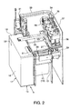
- is an perspective view showing the inkjet printer with the printer case removed.
- FIG. 3
- is a block diagram describing the control system of the inkjet printer.
- FIG. 4
- is a flow chart describing the flow of control by the control unit.
- FIG. 5
- is a plan view of the printable part of the ink cartridge.
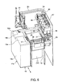
- FIG. 6
- is an perspective view showing an inkjet printer according to another embodiment of the invention with the printer case removed.
- A fluid discharge device and a control method for a fluid discharge device according to a preferred embodiment of the invention are described below with reference to the accompanying figures.
-
FIG. 1 to FIG. 5 describe an inkjet printer as an example of a fluid discharge device according to a preferred embodiment of the invention. - The structure of an inkjet printer as a preferred embodiment of a fluid discharge device according to the present invention is described next.
- The
inkjet printer 1 shown inFIG. 1 is a color printer that prints on recording paper delivered from a paper roll using a plurality of color inks (four inks, black, cyan, magenta, and yellow in this embodiment of the invention). Acover 5 is disposed to open and close freely at the front of theprinter case 2 that houses the printer. Apower switch 3, a paper feed switch, and indicators are also disposed on the front of theprinter case 2. - As shown in
FIG. 2 , opening thecover 5 opens apaper storage unit 13 that holds thepaper roll 11, which is therecording paper 12 used as the print medium wound into a roll, so that thepaper roll 11 can be loaded or unloaded, i.e., replaced. - Also inside, a basically rectangular box-like fluid tank, an
ink cartridge 17 in this case, can be inserted to a (cartridge)loading unit 15 in the direction of arrow A, and can be removed by moving theink cartridge 17 in the opposite direction. - A
carriage 23 on which a head, aninkjet head 21 in this case, is mounted is disposed above thepaper storage unit 13 inside theprinter case 2. Thecarriage 23 is supported to be freely movable across the width of the paper on aguide member 25 that extends widthwise to thepaper roll 11, and can be moved bidirectionally above aplaten 28 across the width of thepaper roll 11 by an endless belt (not shown in the figure) extending widthwise to thepaper roll 11 and acarriage motor 26 that drives the endless belt. Theinkjet head 21 discharges ink to print on therecording paper 12 delivered from thepaper roll 11. - As shown in the figure, the standby position (home position) of the bidirectionally
movable carriage 23 is on the side of thepaper roll 11 opposite to thecartridge loading unit 15. A wasteink vacuum mechanism 29 for vacuuming and disposing of ink inside the ink nozzles of theinkjet head 21 exposed from the bottom of thecarriage 23 is disposed below the standby position. - The
ink cartridge 17 stores a plurality of color ink packs, not shown, inside thecartridge case 18 that forms the housing of the fluid tank in this example of an inkjet printer. Each of the ink packs inside theink cartridge 17 is made of a flexible material and is sealed with ink stored inside. When theink cartridge 17 is loaded into thecartridge loading unit 15, a respective ink supply needle, not shown, disposed on thecartridge loading unit 15 side is inserted to and connects with an ink supply opening of each ink pack. This ink supply openings are formed on the surface of theink cartridge 17 on the insertion side when theink cartridge 17 is inserted in the direction of arrow A. Anink path 31 fixed inside theprinter case 2 is connected to the ink supply needles of thecartridge loading unit 15, and one end of a flexibleink supply tube 33 having a respective channel for each color is connected to theink path 31. - The other end of the
ink supply tube 33 is connected toink pump units 34, of which for each color (channel) a respective one is disposed on thecarriage 23. Eachink pump unit 34 is disposed above theinkjet head 21, and connected to a respective self-sealingunit 36 connected to theinkjet head 21. - In addition to the
inkjet head 21, theink pump units 34 and the self-sealingunits 36 are disposed in unison with thecarriage 23. - As a result, ink from each ink pack inside the
ink cartridge 17 is supplied to the ink nozzles of theinkjet head 21 from the respective ink supply needle of thecartridge loading unit 15 through theink path 31, the respective channel of theink supply tube 33, theink pump unit 34 for the respective color, and the self-sealingunit 36 for the respective color. - The
ink pump units 34 pull ink from theink cartridge 17 by means of aregulator panel 37 that causes theink pump units 34 to operate by means of the force ofcarriage 23 movement. Theregulator panel 37 is disposed at the front in the direction ofcarriage 23 movement to the standby position. - Each
ink pump unit 34 has arespective rocker arm 35. When therocker arm 35 contacts theregulator panel 37 as a result of thecarriage 23 moving to the standby position, therocker arm 35 rocks and drives an internal pump of the associatedink pump unit 34. This causes the pump to pull ink from the corresponding ink pack in theink cartridge 17. - Ink that is vacuumed from the
inkjet head 21 by the wasteink vacuum mechanism 29 when theinkjet head 21 is cleaned is returned to theink cartridge 17 as waste ink and is stored in a waste ink absorber inside theink cartridge 17. - Because the
ink cartridge 17 loaded into thecartridge loading unit 15 of theinkjet printer 1 is basically box-shaped, aprintable part 51 is disposed at part of the outsidetop surface 19 of theink cartridge 17 when loaded in thecartridge loading unit 15. Thisprintable part 51 may be a printable" label which can be peeled off from fluid tank, or it may be made printable by appropriately providing an ink-absorbing layer. - When the
ink cartridge 17 is loaded in thecartridge loading unit 15, theprintable part 51 of theink cartridge 17 is positioned substantially flush with therecording paper 12 on theplaten 28, that is, the surface to which theinkjet head 21 prints (discharges fluid). - Note that the
carriage 23 can also travel past the printing area of therecording paper 12 to thecartridge loading unit 15 side, and can print on theprintable part 51 of theink cartridge 17 loaded in thecartridge loading unit 15. - A
storage unit 52, such as an IC chip substrate, is disposed on theink cartridge 17 on a side surface away from the location of theprintable part 51. An ink usage history including such information as the remaining ink quantity, waste ink quantity, first date of use, and device identification information can be written to and read from thestorage unit 52. Information about the type of ink, for example, is also stored to thestorage unit 52 in addition to the ink usage history. - The
inkjet printer 1 also has a reading/writing unit 61, also referred to as a reader/writer, described below that reads and writes the ink usage history to thestorage unit 52 of theink cartridge 17. - As shown in
FIG. 3 , acontrol unit 60, also referred to as a controller, of theinkjet printer 1 sends control signals to theinkjet head 21 and thecarriage motor 26 to control driving theinkjet head 21 and thecarriage motor 26 and print on therecording paper 12. The reader/writer 61 that reads and writes the ink usage history in thestorage unit 52 is connected to thecontrol unit 60, and thecontrol unit 60 accesses the ink usage history in thestorage unit 52 through the reader/writer 61. - Processing the ink usage history by the
control unit 60 is described next with reference to the flow chart inFIG. 4 . - When printing starts (step S1), the
control unit 60 reads the ink information (ink usage history) stored in thestorage unit 52 of theink cartridge 17 loaded in thecartridge loading unit 15 by the reader/writer 61 (step S2). If the loadedink cartridge 17 is new, thecontrol unit 60 writes the first date of use and device identification information for the device using theink cartridge 17 to thestorage unit 52. - Thereafter at the ink information update timing, which occurs at a predetermined interval or when the
inkjet head 21 is cleaned by the wasteink vacuum mechanism 29, for example, (step S3 returns Yes), thecontrol unit 60 determines the remaining ink quantity and waste ink quantity in theink cartridge 17 7 based on how much ink has been consumed by the printing process and how much ink was vacuumed from theinkjet head 21 by the wasteink vacuum mechanism 29, respectively, and writes the remaining ink quantity and waste ink quantity to thestorage unit 52 as ink information (step S4). - At this time the
control unit 60 controls theinkjet head 21 and thecarriage motor 26 to move theinkjet head 21 past the printing area of therecording paper 12 to a position above theink cartridge 17, and to print the remaining ink quantity information in the ink information written to thestorage unit 52 to theprintable part 51 of theink cartridge 17 by the inkjet head 21 (step S5). - As shown in
FIG. 5 , one method of printing the remaining ink quantity information is to provide a blankrectangular indication bar 51 a in theprintable part 51 and then gradually fill theindication bar 51 a from one end according to the remaining ink quantity, and print a message such as INK EMPTY on theprintable part 51 when the remaining ink quantity goes to a zero level. - Note that because the color ink packs for the four colors black, cyan, magenta, and yellow that are stored inside the
ink cartridge 17 cannot be individually replaced in this embodiment of the invention, the remaining ink quantity printed inFIG. 5 corresponds to the lowest one of the levels of the four colors black, cyan, magenta, and yellow, and theink cartridge 17 is replaced when any one color is depleted. The remaining ink quantity can obviously also be printed for each color separately. - When the process of printing on the
recording paper 12 ends (step S6 returns Yes), thecontrol unit 60 also ends the ink information processing. - The inkjet printer and the control method for the same described in the foregoing embodiment can both store the ink usage history of the
ink cartridge 17 in anstorage unit 52 and print the information on aprintable part 51 on the outside of theink cartridge 17 by theinkjet head 21 for printing to recordingpaper 12. As a result, the user can easily visually confirm ink information, such as how much ink is left from theink cartridge 17, after theink cartridge 17 has been removed from thecartridge loading unit 15. In addition, when theink cartridge 17 is reloaded into thecartridge loading unit 15, the ink information can be acquired by reading the ink information stored in thestorage unit 52 using the reader/writer 61. - As a result, even if
multiple ink cartridges 17 become mixed together, the remaining ink quantity in eachink cartridge 17 can be visually confirmed without loading eachink cartridge 17 into thecartridge loading unit 15 and reading the ink information from thestorage unit 52, and mistakenly switching new andold ink cartridges 17 when replacing theink cartridge 17 can be avoided. - In addition, the
ink cartridge 17 container and internal ink packs do not need to be transparent, and ink deterioration resulting from using transparent materials is prevented. - Furthermore, because the
control unit 60 prints the ink information on theink cartridge 17 synchronized to the ink information update timing, which is the timing when the ink information is written to thestorage unit 52, the ink information written in thestorage unit 52 and the ink information printed on the outside of theink cartridge 17 match. - Furthermore, because part of the outside of the
ink cartridge 17 loaded in thecartridge loading unit 15 is disposed flush to the surface of therecording paper 12 on which theinkjet head 21 prints, the ink information can be easily printed on the outside of theink cartridge 17 by theinkjet head 21 by moving theinkjet head 21 from the area for printing to therecording paper 12 to theink cartridge 17 side. - In addition, because the
storage unit 52 is arranged remote from theprintable part 51, there is little soiling of thestorage unit 52 by printing to theprintable part 51, and read/write errors by the reader/writer 61 are reduced. - The invention is not limited to the embodiment described above and can be modified and improved in many ways. For example, the ink cartridge could be shaped as shown in
FIG. 6 . -
FIG. 6 corresponds toFIG. 2 of the foregoing embodiment, and parts with the same or similar function as described in the preceding embodiment are identified using the same reference numerals below. - The differences between this
ink cartridge 17a and theink cartridge 17 described above are that the side where theprintable part 51 is disposed is formed as a step projecting above the flattop surface 19b with theprintable part 51 disposed to thetop protruding surface 19a, and the IC chip substrate (storage unit) 52a is disposed on thetop surface 19b at a position away from theprintable part 51. - This aspect of the invention is described next with reference to
FIG. 6 . - The
ink cartridge 17a has a box-like shape with the surface on theprintable part 51 side having twoportions printable part 51 is disposed is the protruding (at a higher level as seen inFig. 6 )surface 19a. Because the printable area is on this protrudingsurface 19a, the information printed in theprintable part 51 is easy to read and the information is easy to confirm. In addition, if theink cartridge 17a is placed resting on theprintable part 51, stability is poor and theink cartridge 17a easily tips over because this surface is stepped and not flat, and theink cartridge 17a is therefore unlikely to be placed with the protrudingsurface 19a down. Furthermore, even if theink cartridge 17a is placed resting on theprintable part 51, the stepped shape means that theink cartridge 17a will be tilted and the protrudingsurface 19a will therefore not be flat against the surface. Dust, particulate, and other foreign matter will therefore not stick to theprintable part 51 when set down and the quality of printing to theprintable part 51 by theinkjet head 21 will not drop. These effects can be further enhanced by reducing the size of the protrudingsurface 19a. In this embodiment of the invention the protrudingsurface 19a is formed on the side of the rectangularprintable part 51 with the smallest area. - Regarding the
storage unit 52a, even if theink cartridge 17a is placed with theprintable part 51 side down, the protrudingsurface 19a prevents thetop surface 19b from touching the surface. Therefore, thestorage unit 52a can be protected from dust and other foreign matter on the surface it touches. - The invention is not limited to the embodiments described above and can be further modified in many ways.
- For example, waste ink vacuumed by the waste
ink vacuum mechanism 29 is held in a waste ink absorber in theink cartridge 17, but the waste ink storage unit of theink cartridge 17 can be formed without the waste ink absorber. In this case there is no need to replace the waste ink absorber when the cartridge is reused, and the cartridge can be reused by simply wiping out the waste ink. - The
surface portion 19a with theprintable part 51 of theink cartridge 17 is disposed flush with therecording paper 12 on theplaten 28, that is, the printing surface (discharge surface) of theinkjet head 21, when loaded in thecartridge loading unit 15, but if the discharge performance of theinkjet head 21 is good, theprintable part 51 does not need to be flush with therecording paper 12. Forming them flush, however, enables printing with the same quality as on the roll paper. - If a printable label that can be peeled off without leaving anything on the cartridge is used as the
printable part 51, the number of steps required to remove the label when reusing the ink cartridge can be reduced. - Furthermore, the
control unit 60 acquires the remaining ink quantity and waste ink quantity in theink cartridge 17 based on the amount of ink consumed for printing and the amount of ink vacuumed from theinkjet head 21 by the wasteink vacuum mechanism 29, but it is only necessary to determine the remaining ink quantity and the waste ink quantity does not need to be used. - In addition to inkjet printers as described above, the fluid discharge device according to the present invention can be applied in fluid discharge devices equipped with fluid discharge heads for discharging a variety of fluids, including color agent discharge heads used in manufacturing color filters for liquid crystal displays, electrode material discharge heads used for forming electrodes in organic EL display and FED (field emission display) devices, and bio-organic material discharge heads used in biochip manufacture. The invention can also be used in a reagent discharge device as a precision pipette. The fluid used is also not limited to ink, and can be any material enabling recording a fluid usage history by discharging the fluid to the outside surface of the fluid tank.
Claims (11)
- A fluid discharge device comprising:a loading unit (15) adapted to have a fluid tank (17; 17a) storing a fluid loaded thereto and unloaded therefrom;a head (21) adapted to discharge fluid supplied from a loaded fluid tank (17; 17a);a reading/writing unit (61) adapted to read and write fluid usage history information relating to the use of fluid in the loaded fluid tank (17; 17a) to a storage unit (52) disposed at the fluid tank (17; 17a); anda controller (60) adapted to record at least a part of the fluid usage history information written to the storage unit (52) on an outside surface (19a) of a housing of the fluid tank (17; 17a) by the head (21).
- The fluid discharge device described in claim 1, wherein the fluid tank (17; 17a) loaded in the loading unit (15) has on a side facing the head (21) a label that can be printed by the head (21).
- The fluid discharge device described in claim 1 or 2, wherein the controller (60) is adapted to record said at least a part of the fluid usage history information synchronized to the write timing of the fluid usage history information to the storage unit (52) by said reading/writing unit (61).
- The fluid discharge device described in any of claims 1 to 3, wherein a part of the outside surface (19a) of the housing of the fluid tank (17; 17a) loaded in the loading unit (15) is disposed flush to the discharge surface of the medium to which the head (21) is adapted to discharge fluid.
- A control method for a fluid discharge device havinga loading unit (15) with a fluid tank (17; 17a) storing a fluid loaded therein,a head (21) for discharging fluid supplied from the fluid tank (17; 17a);a reading/writing unit (61) for reading and writing fluid usage history information relating to the use of fluid in the fluid tank (17; 17a) to a storage unit (52) disposed at the fluid tank (17; 17a);the method comprising:a) discharging fluid from the head (21) of the fluid discharge device;b) writing fluid usage history information relating to the use of fluid in the fluid tank (17; 17a) to said storage unit (52); andc) using said head (21) to record at least a part of the fluid usage history information written in step b) on an outside surface (19a) of the fluid tank (17; 17a).
- The method described in claim 5, wherein step c) is performed in synchronization with step b).
- A fluid tank adapted to be used in the fluid discharge device of any one of claims 1 to 4 and having fluid inside, comprising:a housing;a protruding part that protrudes from a part of the housing; anda printable part that can be printed, the printable part being provided on the distal surface of the protruding part.
- The fluid tank described in claim 7, wherein the printable part is adapted to be printed on by means of the fluid in the fluid tank (17; 17a).
- The fluid tank described claim 7 or 8, wherein a storage unit (52) that stores data used indicating the fluid amount remaining in the fluid tank (17; 17a) is disposed at a position on the housing away from the printable part.
- The fluid tank described in any of claims 7 to 9, wherein the storage unit (52) is disposed on the surface from which the protruding part protrudes.
- The fluid tank described in any of claims 7 to 10, wherein the fluid tank (17; 17a) has a basically rectangular box shape, and the protruding part is disposed on a surface having an area smaller than that of other surfaces of the box shape.
Applications Claiming Priority (2)
| Application Number | Priority Date | Filing Date | Title |
|---|---|---|---|
| JP2008155290 | 2008-06-13 | ||
| JP2009133781A JP5287518B2 (en) | 2008-06-13 | 2009-06-03 | Liquid ejection device |
Publications (2)
| Publication Number | Publication Date |
|---|---|
| EP2133205A1 true EP2133205A1 (en) | 2009-12-16 |
| EP2133205B1 EP2133205B1 (en) | 2015-03-25 |
Family
ID=41050303
Family Applications (1)
| Application Number | Title | Priority Date | Filing Date |
|---|---|---|---|
| EP09007616.7A Not-in-force EP2133205B1 (en) | 2008-06-13 | 2009-06-09 | Fluid discharge device, control method for a fluid discharge device, and fluid tank |
Country Status (4)
| Country | Link |
|---|---|
| US (1) | US8172349B2 (en) |
| EP (1) | EP2133205B1 (en) |
| JP (1) | JP5287518B2 (en) |
| CN (1) | CN101602285B (en) |
Cited By (1)
| Publication number | Priority date | Publication date | Assignee | Title |
|---|---|---|---|---|
| CN108340666A (en) * | 2018-04-24 | 2018-07-31 | 海宁酷彩数码科技有限公司 | A kind of printing device of food package film |
Families Citing this family (5)
| Publication number | Priority date | Publication date | Assignee | Title |
|---|---|---|---|---|
| JP5891708B2 (en) | 2011-10-28 | 2016-03-23 | セイコーエプソン株式会社 | Printing device |
| JP6264083B2 (en) * | 2013-09-30 | 2018-01-24 | セイコーエプソン株式会社 | Recording device |
| JP6217466B2 (en) * | 2014-03-07 | 2017-10-25 | ブラザー工業株式会社 | Liquid ejection device |
| US9315033B2 (en) * | 2014-03-14 | 2016-04-19 | Seiko Epson Corporation | Recording apparatus |
| JP2019166708A (en) * | 2018-03-23 | 2019-10-03 | セイコーエプソン株式会社 | Liquid injection device and driving method for liquid injection device |
Citations (5)
| Publication number | Priority date | Publication date | Assignee | Title |
|---|---|---|---|---|
| EP0985537A1 (en) * | 1998-05-25 | 2000-03-15 | Seiko Epson Corporation | Ink cartridge, ink-jet printing apparatus, and refilling device |
| JP2003011469A (en) | 2001-06-29 | 2003-01-15 | Casio Comput Co Ltd | Consumable goods unit and imaging apparatus comprising it |
| US20040012645A1 (en) * | 2002-07-16 | 2004-01-22 | Michael Kinalski | System and method for filling a reservoir |
| US20050219336A1 (en) * | 2004-03-31 | 2005-10-06 | Canon Kabushiki Kaisha | Printing apparatus, inkjet printhead, and cartridge type discrimination method |
| EP2055488A1 (en) * | 2006-08-08 | 2009-05-06 | Seiko Epson Corporation | Liquid container and liquid consuming device |
Family Cites Families (20)
| Publication number | Priority date | Publication date | Assignee | Title |
|---|---|---|---|---|
| US5049898A (en) * | 1989-03-20 | 1991-09-17 | Hewlett-Packard Company | Printhead having memory element |
| EP1234675B1 (en) * | 1989-08-05 | 2007-05-09 | Canon Kabushiki Kaisha | Ink jet recording apparatus and ink cartridge for the apparatus |
| US6170939B1 (en) * | 1992-07-31 | 2001-01-09 | Canon Kabushiki Kaisha | Liquid storing container for recording apparatus |
| JPH06320732A (en) | 1993-05-17 | 1994-11-22 | Canon Inc | Ink jet recorder |
| JPH07205419A (en) | 1994-01-26 | 1995-08-08 | Canon Inc | Ink jet device |
| JP2891090B2 (en) | 1994-02-18 | 1999-05-17 | ブラザー工業株式会社 | Printing device |
| US20010033308A1 (en) * | 1994-03-11 | 2001-10-25 | Hitoshi Fujimoto | Recovering apparatus for recovering a status of an ink jet recording head |
| JPH11126008A (en) | 1997-10-24 | 1999-05-11 | Canon Inc | Cartridge and recycle system |
| US6024440A (en) * | 1998-01-08 | 2000-02-15 | Lexmark International, Inc. | Nozzle array for printhead |
| JP2001246822A (en) | 1999-12-27 | 2001-09-11 | Canon Inc | Printer, information method in printer, control method for printer, external apparatus, control method for external apparatus, and recording medium |
| JP2001253148A (en) | 2000-03-14 | 2001-09-18 | Funai Electric Co Ltd | Ink-jet printer |
| DK1679196T3 (en) * | 2000-06-15 | 2008-08-25 | Seiko Epson Corp | Liquid filling process, liquid container and process for making it |
| ES2265384T3 (en) * | 2000-12-01 | 2007-02-16 | Seiko Epson Corporation | SYSTEM, APPARATUS AND METHOD TO ISSUE RECEIPTS AND MAKE PUBLICITY. |
| US6910812B2 (en) * | 2001-05-15 | 2005-06-28 | Peregrine Semiconductor Corporation | Small-scale optoelectronic package |
| EP1314565B1 (en) * | 2001-11-26 | 2006-09-20 | Seiko Epson Corporation | Ink cartridge and ink jet record apparatus using ink cartridge |
| SG115552A1 (en) * | 2002-07-18 | 2005-10-28 | Seiko Epson Corp | Cartridge and printing apparatus |
| JP2004209970A (en) * | 2002-12-16 | 2004-07-29 | Canon Inc | Liquid tank and recording device |
| JP4617741B2 (en) * | 2004-06-30 | 2011-01-26 | コニカミノルタホールディングス株式会社 | Image recording device |
| JP4613667B2 (en) * | 2005-03-31 | 2011-01-19 | セイコーエプソン株式会社 | Liquid detection device, liquid container, and manufacturing method of liquid detection device |
| JP2008087425A (en) * | 2006-10-04 | 2008-04-17 | Seiko Epson Corp | Coloring agent management device, its control method, its control program and printer |
-
2009
- 2009-06-03 JP JP2009133781A patent/JP5287518B2/en not_active Expired - Fee Related
- 2009-06-09 EP EP09007616.7A patent/EP2133205B1/en not_active Not-in-force
- 2009-06-09 CN CN2009102033704A patent/CN101602285B/en not_active Expired - Fee Related
- 2009-06-15 US US12/484,402 patent/US8172349B2/en active Active
Patent Citations (5)
| Publication number | Priority date | Publication date | Assignee | Title |
|---|---|---|---|---|
| EP0985537A1 (en) * | 1998-05-25 | 2000-03-15 | Seiko Epson Corporation | Ink cartridge, ink-jet printing apparatus, and refilling device |
| JP2003011469A (en) | 2001-06-29 | 2003-01-15 | Casio Comput Co Ltd | Consumable goods unit and imaging apparatus comprising it |
| US20040012645A1 (en) * | 2002-07-16 | 2004-01-22 | Michael Kinalski | System and method for filling a reservoir |
| US20050219336A1 (en) * | 2004-03-31 | 2005-10-06 | Canon Kabushiki Kaisha | Printing apparatus, inkjet printhead, and cartridge type discrimination method |
| EP2055488A1 (en) * | 2006-08-08 | 2009-05-06 | Seiko Epson Corporation | Liquid container and liquid consuming device |
Cited By (1)
| Publication number | Priority date | Publication date | Assignee | Title |
|---|---|---|---|---|
| CN108340666A (en) * | 2018-04-24 | 2018-07-31 | 海宁酷彩数码科技有限公司 | A kind of printing device of food package film |
Also Published As
| Publication number | Publication date |
|---|---|
| CN101602285B (en) | 2011-05-11 |
| US20090315928A1 (en) | 2009-12-24 |
| JP5287518B2 (en) | 2013-09-11 |
| JP2010018024A (en) | 2010-01-28 |
| US8172349B2 (en) | 2012-05-08 |
| CN101602285A (en) | 2009-12-16 |
| EP2133205B1 (en) | 2015-03-25 |
Similar Documents
| Publication | Publication Date | Title |
|---|---|---|
| KR100556001B1 (en) | Ink jet cartridge with separately replaceable ink reservoir | |
| US7845750B2 (en) | Ink jet type recording apparatus, ink type information setting method in the apparatus and ink cartridge used in the apparatus | |
| US8075115B2 (en) | Mountable apparatus and board having an installation status notifier | |
| EP2133205B1 (en) | Fluid discharge device, control method for a fluid discharge device, and fluid tank | |
| EP2100738B1 (en) | Image forming apparatus, image forming method, and recording medium storing program that causes the apparatus to execute the method | |
| CN101005954B (en) | Image forming device | |
| JP5585154B2 (en) | Liquid injection system | |
| KR102139622B1 (en) | Liquid ejecting apparatus | |
| TWM315161U (en) | Ink cartridge, ink-jet printing apparatus, and refilling device | |
| JP2010269608A (en) | Control method of printing apparatus | |
| JP5186718B2 (en) | Printing device | |
| US8186816B2 (en) | Liquid container, board, and method of rewriting liquid information | |
| JP4805690B2 (en) | Image forming apparatus | |
| US11813880B2 (en) | Liquid ejection apparatus and delivery system for liquid ejection head | |
| JP3478332B2 (en) | Ink jet recording device | |
| JP2007118339A (en) | Inkjet printer, method for restoring function of inkjet printer, and program | |
| JP2007144629A (en) | Image forming device | |
| JP7180099B2 (en) | Liquid ejector | |
| US7866803B2 (en) | Replaceable printer component with electronic tag | |
| JP4193862B2 (en) | Ink type information setting method in ink jet recording apparatus | |
| JP4208660B2 (en) | Image forming apparatus, ink supply mechanism, drive control program, and recording medium storing drive control program | |
| JP2004330503A (en) | Image formation device | |
| JP2003072098A (en) | Printer | |
| JP2004122644A (en) | Recording device, computer program, computer system, and recording method | |
| JP2007160714A (en) | Liquid ejector |
Legal Events
| Date | Code | Title | Description |
|---|---|---|---|
| PUAI | Public reference made under article 153(3) epc to a published international application that has entered the european phase |
Free format text: ORIGINAL CODE: 0009012 |
|
| AK | Designated contracting states |
Kind code of ref document: A1 Designated state(s): AT BE BG CH CY CZ DE DK EE ES FI FR GB GR HR HU IE IS IT LI LT LU LV MC MK MT NL NO PL PT RO SE SI SK TR |
|
| 17P | Request for examination filed |
Effective date: 20100610 |
|
| GRAP | Despatch of communication of intention to grant a patent |
Free format text: ORIGINAL CODE: EPIDOSNIGR1 |
|
| INTG | Intention to grant announced |
Effective date: 20140822 |
|
| RIC1 | Information provided on ipc code assigned before grant |
Ipc: B41J 2/175 20060101AFI20140808BHEP Ipc: B41J 3/407 20060101ALI20140808BHEP Ipc: B41J 15/04 20060101ALI20140808BHEP |
|
| GRAS | Grant fee paid |
Free format text: ORIGINAL CODE: EPIDOSNIGR3 |
|
| GRAA | (expected) grant |
Free format text: ORIGINAL CODE: 0009210 |
|
| AK | Designated contracting states |
Kind code of ref document: B1 Designated state(s): AT BE BG CH CY CZ DE DK EE ES FI FR GB GR HR HU IE IS IT LI LT LU LV MC MK MT NL NO PL PT RO SE SI SK TR |
|
| REG | Reference to a national code |
Ref country code: GB Ref legal event code: FG4D |
|
| REG | Reference to a national code |
Ref country code: CH Ref legal event code: EP |
|
| REG | Reference to a national code |
Ref country code: IE Ref legal event code: FG4D |
|
| REG | Reference to a national code |
Ref country code: DE Ref legal event code: R096 Ref document number: 602009030128 Country of ref document: DE Effective date: 20150507 |
|
| REG | Reference to a national code |
Ref country code: AT Ref legal event code: REF Ref document number: 717619 Country of ref document: AT Kind code of ref document: T Effective date: 20150515 |
|
| PG25 | Lapsed in a contracting state [announced via postgrant information from national office to epo] |
Ref country code: LT Free format text: LAPSE BECAUSE OF FAILURE TO SUBMIT A TRANSLATION OF THE DESCRIPTION OR TO PAY THE FEE WITHIN THE PRESCRIBED TIME-LIMIT Effective date: 20150325 Ref country code: SE Free format text: LAPSE BECAUSE OF FAILURE TO SUBMIT A TRANSLATION OF THE DESCRIPTION OR TO PAY THE FEE WITHIN THE PRESCRIBED TIME-LIMIT Effective date: 20150325 Ref country code: HR Free format text: LAPSE BECAUSE OF FAILURE TO SUBMIT A TRANSLATION OF THE DESCRIPTION OR TO PAY THE FEE WITHIN THE PRESCRIBED TIME-LIMIT Effective date: 20150325 Ref country code: FI Free format text: LAPSE BECAUSE OF FAILURE TO SUBMIT A TRANSLATION OF THE DESCRIPTION OR TO PAY THE FEE WITHIN THE PRESCRIBED TIME-LIMIT Effective date: 20150325 |
|
| REG | Reference to a national code |
Ref country code: AT Ref legal event code: MK05 Ref document number: 717619 Country of ref document: AT Kind code of ref document: T Effective date: 20150325 |
|
| REG | Reference to a national code |
Ref country code: LT Ref legal event code: MG4D |
|
| PG25 | Lapsed in a contracting state [announced via postgrant information from national office to epo] |
Ref country code: GR Free format text: LAPSE BECAUSE OF FAILURE TO SUBMIT A TRANSLATION OF THE DESCRIPTION OR TO PAY THE FEE WITHIN THE PRESCRIBED TIME-LIMIT Effective date: 20150626 Ref country code: LV Free format text: LAPSE BECAUSE OF FAILURE TO SUBMIT A TRANSLATION OF THE DESCRIPTION OR TO PAY THE FEE WITHIN THE PRESCRIBED TIME-LIMIT Effective date: 20150325 |
|
| PG25 | Lapsed in a contracting state [announced via postgrant information from national office to epo] |
Ref country code: NL Free format text: LAPSE BECAUSE OF FAILURE TO SUBMIT A TRANSLATION OF THE DESCRIPTION OR TO PAY THE FEE WITHIN THE PRESCRIBED TIME-LIMIT Effective date: 20150325 |
|
| PG25 | Lapsed in a contracting state [announced via postgrant information from national office to epo] |
Ref country code: PT Free format text: LAPSE BECAUSE OF FAILURE TO SUBMIT A TRANSLATION OF THE DESCRIPTION OR TO PAY THE FEE WITHIN THE PRESCRIBED TIME-LIMIT Effective date: 20150727 Ref country code: EE Free format text: LAPSE BECAUSE OF FAILURE TO SUBMIT A TRANSLATION OF THE DESCRIPTION OR TO PAY THE FEE WITHIN THE PRESCRIBED TIME-LIMIT Effective date: 20150325 Ref country code: ES Free format text: LAPSE BECAUSE OF FAILURE TO SUBMIT A TRANSLATION OF THE DESCRIPTION OR TO PAY THE FEE WITHIN THE PRESCRIBED TIME-LIMIT Effective date: 20150325 Ref country code: RO Free format text: LAPSE BECAUSE OF FAILURE TO SUBMIT A TRANSLATION OF THE DESCRIPTION OR TO PAY THE FEE WITHIN THE PRESCRIBED TIME-LIMIT Effective date: 20150325 Ref country code: SK Free format text: LAPSE BECAUSE OF FAILURE TO SUBMIT A TRANSLATION OF THE DESCRIPTION OR TO PAY THE FEE WITHIN THE PRESCRIBED TIME-LIMIT Effective date: 20150325 Ref country code: CZ Free format text: LAPSE BECAUSE OF FAILURE TO SUBMIT A TRANSLATION OF THE DESCRIPTION OR TO PAY THE FEE WITHIN THE PRESCRIBED TIME-LIMIT Effective date: 20150325 |
|
| PG25 | Lapsed in a contracting state [announced via postgrant information from national office to epo] |
Ref country code: AT Free format text: LAPSE BECAUSE OF FAILURE TO SUBMIT A TRANSLATION OF THE DESCRIPTION OR TO PAY THE FEE WITHIN THE PRESCRIBED TIME-LIMIT Effective date: 20150325 Ref country code: PL Free format text: LAPSE BECAUSE OF FAILURE TO SUBMIT A TRANSLATION OF THE DESCRIPTION OR TO PAY THE FEE WITHIN THE PRESCRIBED TIME-LIMIT Effective date: 20150325 Ref country code: IS Free format text: LAPSE BECAUSE OF FAILURE TO SUBMIT A TRANSLATION OF THE DESCRIPTION OR TO PAY THE FEE WITHIN THE PRESCRIBED TIME-LIMIT Effective date: 20150725 |
|
| REG | Reference to a national code |
Ref country code: DE Ref legal event code: R097 Ref document number: 602009030128 Country of ref document: DE |
|
| PG25 | Lapsed in a contracting state [announced via postgrant information from national office to epo] |
Ref country code: DK Free format text: LAPSE BECAUSE OF FAILURE TO SUBMIT A TRANSLATION OF THE DESCRIPTION OR TO PAY THE FEE WITHIN THE PRESCRIBED TIME-LIMIT Effective date: 20150325 Ref country code: MC Free format text: LAPSE BECAUSE OF FAILURE TO SUBMIT A TRANSLATION OF THE DESCRIPTION OR TO PAY THE FEE WITHIN THE PRESCRIBED TIME-LIMIT Effective date: 20150325 |
|
| PLBE | No opposition filed within time limit |
Free format text: ORIGINAL CODE: 0009261 |
|
| REG | Reference to a national code |
Ref country code: CH Ref legal event code: PL |
|
| STAA | Information on the status of an ep patent application or granted ep patent |
Free format text: STATUS: NO OPPOSITION FILED WITHIN TIME LIMIT |
|
| PG25 | Lapsed in a contracting state [announced via postgrant information from national office to epo] |
Ref country code: LU Free format text: LAPSE BECAUSE OF FAILURE TO SUBMIT A TRANSLATION OF THE DESCRIPTION OR TO PAY THE FEE WITHIN THE PRESCRIBED TIME-LIMIT Effective date: 20150609 |
|
| 26N | No opposition filed |
Effective date: 20160105 |
|
| REG | Reference to a national code |
Ref country code: IE Ref legal event code: MM4A |
|
| PG25 | Lapsed in a contracting state [announced via postgrant information from national office to epo] |
Ref country code: IE Free format text: LAPSE BECAUSE OF NON-PAYMENT OF DUE FEES Effective date: 20150609 Ref country code: CH Free format text: LAPSE BECAUSE OF NON-PAYMENT OF DUE FEES Effective date: 20150630 Ref country code: LI Free format text: LAPSE BECAUSE OF NON-PAYMENT OF DUE FEES Effective date: 20150630 |
|
| REG | Reference to a national code |
Ref country code: FR Ref legal event code: PLFP Year of fee payment: 8 |
|
| PG25 | Lapsed in a contracting state [announced via postgrant information from national office to epo] |
Ref country code: SI Free format text: LAPSE BECAUSE OF FAILURE TO SUBMIT A TRANSLATION OF THE DESCRIPTION OR TO PAY THE FEE WITHIN THE PRESCRIBED TIME-LIMIT Effective date: 20150325 |
|
| PG25 | Lapsed in a contracting state [announced via postgrant information from national office to epo] |
Ref country code: BE Free format text: LAPSE BECAUSE OF FAILURE TO SUBMIT A TRANSLATION OF THE DESCRIPTION OR TO PAY THE FEE WITHIN THE PRESCRIBED TIME-LIMIT Effective date: 20150325 |
|
| PG25 | Lapsed in a contracting state [announced via postgrant information from national office to epo] |
Ref country code: MT Free format text: LAPSE BECAUSE OF FAILURE TO SUBMIT A TRANSLATION OF THE DESCRIPTION OR TO PAY THE FEE WITHIN THE PRESCRIBED TIME-LIMIT Effective date: 20150325 |
|
| REG | Reference to a national code |
Ref country code: FR Ref legal event code: PLFP Year of fee payment: 9 |
|
| PG25 | Lapsed in a contracting state [announced via postgrant information from national office to epo] |
Ref country code: NO Free format text: LAPSE BECAUSE OF FAILURE TO SUBMIT A TRANSLATION OF THE DESCRIPTION OR TO PAY THE FEE WITHIN THE PRESCRIBED TIME-LIMIT Effective date: 20150625 Ref country code: HU Free format text: LAPSE BECAUSE OF FAILURE TO SUBMIT A TRANSLATION OF THE DESCRIPTION OR TO PAY THE FEE WITHIN THE PRESCRIBED TIME-LIMIT; INVALID AB INITIO Effective date: 20090609 Ref country code: BG Free format text: LAPSE BECAUSE OF FAILURE TO SUBMIT A TRANSLATION OF THE DESCRIPTION OR TO PAY THE FEE WITHIN THE PRESCRIBED TIME-LIMIT Effective date: 20150325 |
|
| PG25 | Lapsed in a contracting state [announced via postgrant information from national office to epo] |
Ref country code: CY Free format text: LAPSE BECAUSE OF FAILURE TO SUBMIT A TRANSLATION OF THE DESCRIPTION OR TO PAY THE FEE WITHIN THE PRESCRIBED TIME-LIMIT Effective date: 20150325 |
|
| PG25 | Lapsed in a contracting state [announced via postgrant information from national office to epo] |
Ref country code: TR Free format text: LAPSE BECAUSE OF FAILURE TO SUBMIT A TRANSLATION OF THE DESCRIPTION OR TO PAY THE FEE WITHIN THE PRESCRIBED TIME-LIMIT Effective date: 20150325 |
|
| REG | Reference to a national code |
Ref country code: FR Ref legal event code: PLFP Year of fee payment: 10 |
|
| PG25 | Lapsed in a contracting state [announced via postgrant information from national office to epo] |
Ref country code: MK Free format text: LAPSE BECAUSE OF FAILURE TO SUBMIT A TRANSLATION OF THE DESCRIPTION OR TO PAY THE FEE WITHIN THE PRESCRIBED TIME-LIMIT Effective date: 20150325 |
|
| PGFP | Annual fee paid to national office [announced via postgrant information from national office to epo] |
Ref country code: FR Payment date: 20200512 Year of fee payment: 12 Ref country code: DE Payment date: 20200527 Year of fee payment: 12 |
|
| PGFP | Annual fee paid to national office [announced via postgrant information from national office to epo] |
Ref country code: IT Payment date: 20200512 Year of fee payment: 12 Ref country code: GB Payment date: 20200527 Year of fee payment: 12 |
|
| REG | Reference to a national code |
Ref country code: DE Ref legal event code: R119 Ref document number: 602009030128 Country of ref document: DE |
|
| GBPC | Gb: european patent ceased through non-payment of renewal fee |
Effective date: 20210609 |
|
| PG25 | Lapsed in a contracting state [announced via postgrant information from national office to epo] |
Ref country code: GB Free format text: LAPSE BECAUSE OF NON-PAYMENT OF DUE FEES Effective date: 20210609 Ref country code: DE Free format text: LAPSE BECAUSE OF NON-PAYMENT OF DUE FEES Effective date: 20220101 |
|
| PG25 | Lapsed in a contracting state [announced via postgrant information from national office to epo] |
Ref country code: FR Free format text: LAPSE BECAUSE OF NON-PAYMENT OF DUE FEES Effective date: 20210630 |
|
| PG25 | Lapsed in a contracting state [announced via postgrant information from national office to epo] |
Ref country code: IT Free format text: LAPSE BECAUSE OF NON-PAYMENT OF DUE FEES Effective date: 20210609 |