EP2132387B1 - Erector scaffold deck fall arrest assembly - Google Patents
Erector scaffold deck fall arrest assembly Download PDFInfo
- Publication number
- EP2132387B1 EP2132387B1 EP08744650.6A EP08744650A EP2132387B1 EP 2132387 B1 EP2132387 B1 EP 2132387B1 EP 08744650 A EP08744650 A EP 08744650A EP 2132387 B1 EP2132387 B1 EP 2132387B1
- Authority
- EP
- European Patent Office
- Prior art keywords
- assembly
- deck structure
- rail
- deck
- pin
- Prior art date
- Legal status (The legal status is an assumption and is not a legal conclusion. Google has not performed a legal analysis and makes no representation as to the accuracy of the status listed.)
- Active
Links
Images


Classifications
-
- E—FIXED CONSTRUCTIONS
- E04—BUILDING
- E04G—SCAFFOLDING; FORMS; SHUTTERING; BUILDING IMPLEMENTS OR AIDS, OR THEIR USE; HANDLING BUILDING MATERIALS ON THE SITE; REPAIRING, BREAKING-UP OR OTHER WORK ON EXISTING BUILDINGS
- E04G5/00—Component parts or accessories for scaffolds
-
- E—FIXED CONSTRUCTIONS
- E04—BUILDING
- E04G—SCAFFOLDING; FORMS; SHUTTERING; BUILDING IMPLEMENTS OR AIDS, OR THEIR USE; HANDLING BUILDING MATERIALS ON THE SITE; REPAIRING, BREAKING-UP OR OTHER WORK ON EXISTING BUILDINGS
- E04G1/00—Scaffolds primarily resting on the ground
- E04G1/15—Scaffolds primarily resting on the ground essentially comprising special means for supporting or forming platforms; Platforms
- E04G1/154—Non-detachably fixed and secured connections between platform and scaffold
-
- E—FIXED CONSTRUCTIONS
- E04—BUILDING
- E04G—SCAFFOLDING; FORMS; SHUTTERING; BUILDING IMPLEMENTS OR AIDS, OR THEIR USE; HANDLING BUILDING MATERIALS ON THE SITE; REPAIRING, BREAKING-UP OR OTHER WORK ON EXISTING BUILDINGS
- E04G5/00—Component parts or accessories for scaffolds
- E04G5/001—Safety or protective measures against falling down relating to scaffoldings
-
- E—FIXED CONSTRUCTIONS
- E04—BUILDING
- E04G—SCAFFOLDING; FORMS; SHUTTERING; BUILDING IMPLEMENTS OR AIDS, OR THEIR USE; HANDLING BUILDING MATERIALS ON THE SITE; REPAIRING, BREAKING-UP OR OTHER WORK ON EXISTING BUILDINGS
- E04G7/00—Connections between parts of the scaffold
- E04G7/02—Connections between parts of the scaffold with separate coupling elements
- E04G7/28—Clips or connections for securing boards
Definitions
- the present invention relates to scaffold work platform systems and, more particularly, to deck structures and fall arrest mechanisms employed in such scaffold work platform systems.
- each level When erecting a scaffold, each level is typically completed before moving up to construct the next level. This may involve moving large quantities of scaffold equipment up hundreds of feet horizontally along a level, until that level is completed.
- a lead erector in a scaffold crew typically has to move along the length of a scaffold prior to installation of fall protection equipment (e.g., guard rails, gates, etc.).
- fall protection equipment e.g., guard rails, gates, etc.
- Many companies mandate total or 100% tie-off, meaning the erector must have the hook to his fall arrest harness attached to an anchor point 100% of the time. This can typically be accomplished by using hooks for each harness and hooking each one to an anchor point further down the scaffold run, then returning back and unhooking the first hook from the first anchor point. If the worker neglects to tie off, or ties off to an anchor point that cannot take the load imposed by a fall, the worker is vulnerable to injury.
- a lead erector in a scaffold crew typically stands on a scaffold before the installation of any fall protection or arrest devices (e.g., guard rails, gates, etc.).
- any fall protection or arrest devices e.g., guard rails, gates, etc.
- such individuals e.g., lead erectors
- Such anchoring points included the scaffold itself, the building adjacent to which the scaffold was typically positioned, or the like, with the intent being to use this point as a fall arrest anchor.
- buildings may not have suitable anchor points, that is, anchor points that can be accessed from the scaffold itself.
- the scaffold itself is typically not designed to serve as a fall arrest anchor, anchor point, or anchor structure.
- the present invention relates to a fall arrest assembly according to claim 1 and also its dependent claims.
- a fall arrest assembly according to claim 1 and also its dependent claims.
- it comprises a deck structure and a rail assembly in operable association with the deck structure, the rail assembly permitting an individual to tie-off in a manner that permits the individual with a range of motion along the deck structure while being tied-off.
- the fall arrest assembly further includes a first uplift hook mechanism connected to or otherwise installed on the deck structure such that the first uplift hook mechanism is employed for both securing the deck structure to and releasing the deck structure from at least one supporting member.
- a fall arrest assembly comprising a deck structure.
- the fall arrest assembly further includes a rail assembly in operable association with the deck structure, which permits an individual to tie-off in a manner that permits the individual with a range of motion along the deck structure.
- a first uplift hook mechanism connectable to the deck structure for engaging to and/or disengaging from a supporting member.
- a plurality of deck hooks connectable to or otherwise installed on the deck structure for connecting the deck structure to the supporting member is additionally provided.
- the fall arrest assembly additionally comprises a deck latch assembly that is connected to the first uplift hook mechanism for facilitating connection of the deck structure to a second deck structure.
- a method of installing a fall arrest assembly comprises providing (i) a deck structure; and (ii) a rail assembly in operable association with the deck structure.
- the method further comprises locating an anchor point on the rail assembly.
- the method additionally comprises climbing onto the deck structure.
- the method comprises attaching one or more lanyard mechanisms to the anchor point on the rail assembly to provide a range of movement on the deck structure when erecting a scaffold assembly.
- the fall arrest tie-off assembly 100 is also referred herein as a fall arrest anchor assembly, fall arrest/arrestor assembly, arrest/arrestor assembly, a work-access system, erector tie-off plank assembly, erector scaffold deck fall arrest assembly and the like.
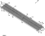
- the fall arrest assembly 100 includes a deck structure 102 (also referred herein as decking, decking structure, plank and the like) having a top surface 104 and a bottom surface 106 (See FIG. 4 ) separated by a thickness 108 and bounded by end cap portions 110 and 112.
- the top and the bottom surfaces 104 and 106 can have a variety of longitudinal corrugations 114 for increasing the strength of the deck structure and for providing a safe walking surface for workers working on the fall arrest assembly 100.
- any type of corrugations, grilles, webs, lattices, etc. can be provided in one or both of the top and the bottom surfaces 104 and 106, respectively. Any of the aforementioned corrugations can additionally be provided on the thickness 108 as well.
- the deck structure 102 can have a hollow core 116, this need not always be the case. Rather, in other embodiments, the deck structure can have a solid core or any other type of core that may be deemed suitable.
- the thickness 108 can vary depending upon the embodiment of the invention based upon, for example, the load handling capability requirements of the scaffold work platform system employing the fall arrest assembly 100.
- the deck structure 102 has a length of about 3,05 m or 2,13 m (10' or 7') and a width of about 0,48 m (19") and is constructed out of aluminum (e.g., non-skid extruded aluminum).
- the weight of the deck structure can be about 18 kg (40 lbs) when the length is about 2,13 m (7') and about 23 kg (50 lbs) when the length is about 3,05 m (10').
- the present fall arrestor assembly 100 can withstand an impact load transmitted to a harness during a fall arrest of up to about 817 kg (1800 lbs). Notwithstanding the aforementioned configuration of the deck structure 102, it is contemplated that the sizes, shapes and the load bearing/transmitting capabilities of the fall arrestor assembly 100, including the decking structure 102 can vary without departing from the spirit and scope of the invention.
- a plurality of deck hooks 118 are connected or otherwise installed at least partially on the end cap portions 110 and 112 of the deck structure 102.
- the deck hooks 118 permit the deck structure 102 to be supported at each end by a scaffold tube or tube-like component (not shown) of the scaffold work platform system that is typically horizontally-disposed to support the deck structure in a level fashion.
- the deck hooks 118 are constructed of aluminum (e.g., solid aluminum). By virtue of constructing the deck structure and the deck hooks of aluminum, a light weighted yet strong fall arrest assembly 100 is provided. Nevertheless, in other embodiments, one or both of the deck structure 102 and the deck hooks 118 can be made of any of a variety of metals, including other rigid materials such as wood.
- deck hooks 118 on the end cap portion 110 and three hooks on the end cap portion 112 in the present embodiment is merely exemplary. In other embodiments, any number of deck hooks 118 as may be deemed necessary for securely connecting the deck structure 102 to the scaffold tube can be employed.
- the fall arrestor assembly 100 includes an uplift hook or hook mechanism 120 connected at least partially to the end cap 112 and the deck structure 102 for securing the fall arrestor assembly 100, and particularly the deck structure, to the scaffold tube member.
- an uplift hook or hook mechanism 120 is included in the fall arrestor assembly 100 and positioned at opposite ends of the deck structure 102 to facilitate connection to other fall arrestor assemblies and/or decking structures. Additional details regarding the uplift hook 120 will be provided in regards with FIGS. 2 and 3 .
- the rail assembly 122 for providing a fall arrest system for ensuring the safety of the worker(s) working on the fall arrestor assembly 100, and additionally for arresting the fall should a worker happen to fall.
- the rail assembly 122 includes a rail mechanism 124 disposed on and running lengthwise on the top surface 104 of the deck structure 102.
- the rail assembly 120 including the rail mechanism 124 will be described in greater detail in FIG. 2 .
- a traveler mechanism 117 (also referred herein as traveler, traveler car, car mechanism or traveler car mechanism) can additionally be engaged to, or otherwise fitted over or with respect to the rail mechanism 124, in a manner well known, for moving the traveler 117 in a direction 115 with respect to the rail mechanism.
- the traveler 117 is in rolling engagement with the rail mechanism 124.
- the traveler 117 can be an anchor device constructed out of, for example, aluminum, and having ball bearings for mounting and moving the traveler on the rail mechanism 124. Notwithstanding the fact that a particular shape, size and configuration of the traveler 117 is shown, it is nevertheless an intention of this intention to include a variety of traveler mechanisms suitable for anchoring to the rail mechanism 124 in a movable manner.
- the traveler 117 can have one or more loops 119 (also referred herein as hooks, latch, latching mechanism etc.) for attaching a safety harness (e.g., lanyard - not shown) of a worker to the traveler for arresting motion in the event of a fall of the worker.
- the loops 119 can be any of variety of loops that are commonly available and frequently employed in scaffold systems.
- the positions of the loops 119 on the traveler 117 can vary.
- the loops can be positioned on the top surface of the traveler. In other embodiments, the loops 119 can be positioned on a side surface thereof.
- multiple loops including, for example, one loop on the top surface and one loop on the side surface, can be present, as shown in FIGS. 1 and 2 .
- the shape and size of the loops 119 can vary depending upon, for example, the shape and size of the safety harness and lanyard employed for engaging with the loops and the arrangement of the scaffold work platform system.
- the traveler 117 provides a mobile anchor device for serving as a latching point (e.g., via the hooks 119) to ensure safety of a worker.
- a mobile anchor device for serving as a latching point (e.g., via the hooks 119) to ensure safety of a worker.
- the rail assembly 122 additionally includes one or more stops or stop mechanisms 126 (e.g., one or more stop pins), described below, that are in operable association with (e.g., built into) the rail or rail mechanism 124 to limit removal and or travel/motion of the traveler 117 with respect to the rail mechanism.
- a deck latch assembly 128 (also referred herein as latch assembly, latch, and the like) that is used for securely connecting one fall arrestor assembly 100 to another fall arrestor assembly.
- the deck latch assembly 128 is shown and described in greater detail with respect to FIG. 4 .
- the deck latch assembly 128 can generally located in a center or central region of the deck structure 102 and typically connected to the uplift hook mechanism 120.
- the deck latch assembly 128 is connected to both of the uplift hook mechanisms 128, although in other embodiments, the deck latch assembly can be connected to a single uplift hook mechanism as well.
- the positioning of the deck latch assembly 128 can vary.
- the deck latch assembly 128 may be positioned at an end of the deck structure 102. Other positions and orientations of the deck latch assembly 128 depending upon the arrangements of the scaffold assembly are contemplated and considered within the scope of the invention.
- the various components of the fall arrestor assembly 100 are described above, it is an intention of this invention to encompass additional components including various refinements to the previously described components.
- various handle structures, support structures etc. can be provided.
- components other than those described above can be present as well.
- the shapes, sizes and numbers of the various components of the fall arrestor assembly 100 can vary to convenience.
- the present invention advantageously provides a work platform system in which the decking structure 102 can be installed and/or removed conveniently by a single individual, called a "lead erector".
- the fall arrestor assembly 100 includes the deck structure 102 bounded by the end cap portions 110 (See FIG. 1 ) and 112 and further having the plurality of deck hooks 118 for securing the decking to the scaffold structure (e.g., tubular scaffold) of the scaffold work platform system.
- the rail assembly 122 in operational association with the deck structure 102 and including the rail mechanism 124 and the stops or stop pin mechanism(s) 126 for limiting removal and/or travel of the traveler 117 that is in association with the rail mechanism.
- the rail mechanism 124 includes one or more rail, rail-like structures or possibly beams and tracks that are disposed on, or otherwise attached to, the top surface 104 of the deck structure 102 at an edge thereof.
- the rail(s) of the rail mechanism 124 can be removably connected to the deck structure by any of a variety of fastening and/or engaging mechanisms in a known manner.
- the rail mechanism 124 can be integrally formed, in a raised or a recessed portion of the deck structure itself thereby providing a rail or rail-like mechanism for receiving a traveler 117 or other movable tie-off apparatus.
- the rail mechanism 124 can be constructed of steel, although other metal or rigid materials can be employed as well. It should be understood that the shape, size and material of construction of the rail mechanism 124 can vary to convenience. Furthermore, the term "rail" is intended to have a broad meaning including any elongate structure to which the traveler 117 can be attached for sliding/moving along the rail.
- the rail mechanism 124 is shown to be disposed longitudinally (lengthwise) on the deck structure 102 at an edge thereof, in other embodiments, the orientation of the rail mechanism can vary.
- the rail mechanism 124 can be disposed horizontally along the edge of the deck structure.
- the rail mechanism 124 can be disposed in a central (or substantially central) portion of the deck structure 102.
- other orientations are intended to be encompassed within the scope of the invention.
- the rail mechanism 124 can be a separate component that is connected directly or indirectly to the deck structure by any of a variety of engaging or fastening mechanisms.
- the rail mechanism 124 can be integrally formed with the deck structure 102, or integrated within or with respect to the deck structure itself.
- the rail mechanism 124 has first and second surfaces 123 and 125, respectively, parallel to the top surface 104 of the deck structure 102, the first and the second surfaces being connected by third and fourth side surfaces 127 and 129, respectively. Further, as shown, one or both of the third and the fourth surfaces 127 and 129, respectively, can have channels or grooves 131 for securely fastening the traveler 117 to the rail mechanism 124.
- the first and the second surfaces 123 and 125 can also have various grooves and channels for providing various latching positions, both from above and below the deck structure 102.
- the traveler 117 can be prevented from moving in a direction transverse to the direction of the rail mechanism.
- An optional orifice 133 passing through at least a portion of the rail mechanism 124 can be provided in some embodiments to reduce the overall weight of the rail assembly 122.
- Other components including, for example, locking mechanisms for holding the traveler 117 and the loops 119 in position can additionally be employed.
- Various other components can also be used in conjunction with, or as part of the rail mechanism 124 without departing from the scope of the invention.
- the stops or stop pins 126 move in a vertical fashion when the decking structure is placed and secured with regard to a scaffold assembly in a level horizontal fashion. In this way, the one or more of the stop pins 126 extend and/or retract to limit removal and/or motion of the traveler 117 that is in association with the rail mechanism 124. In at least some embodiments, the stop or stop pins 126 have a default position that is in the extended (stop) position.
- the traveler 117 to which a harness of an individual (e.g., a lead erector) is connected to arrest a fall remains between to extended stop pin mechanisms 126 so as to limit the movement of a traveler car.
- the one or more stops or stop pins 126 are in an extended (stop) position when the decking or plank structure 102 is not connected to or installed at a given end of the decking structure 102.
- the stops or stop pin mechanisms 126 automatically retract or recede into the rail, for example, below the top surface 123 of the rail mechanism 124 when another decking structure is connected to decking structure 102 in end-to-end fashion, so as to permit an installer to move out onto the next, connected decking structure.
- the one or more stops or stop pin mechanisms 126 are to extend once again in, for example, a stop position, when such a second deck is removed from its end-to-end position.
- FIG. 3 an enlarged, bottom end view of the bottom surface (or underside) of the deck structure 102 showing the uplift mechanism 120 and the stop mechanism 126 (See FIG. 2 ) in greater detail is shown in accordance with at least some embodiments of the present invention.
- the uplift hook mechanism 120 is located at a central or substantially central portion of the deck structure 102 substantially in-line with the deck latch assembly 128 (shown in FIG. 4 ). Additionally, the uplift hook mechanism 120 is positioned such that it protrudes from one end of the deck structure 102 for contacting an underside of the scaffold tube member, which as previously mentioned is typically horizontally disposed with respect to the deck structure.
- the uplift hook mechanism 120 is connected to the deck structure 102 via bolts 130 passing through the uplift hook mechanism and structural element 132.
- a plurality of structural elements 132 connecting the uplift hook mechanism to the deck structure 102 via the bolts 130 are present.
- two structural elements 132 connecting the uplift hook mechanism 120 to the deck structure 102 are shown.
- more than two, or potentially a single structural element for connecting the uplift hook mechanisms to the deck structure 102 can be employed depending upon the length of the deck structure and the dimensions of the uplift hook mechanism 120.
- the uplift hook mechanism 120 is springloaded such that the uplift hook mechanism can retract as the deck structure 102 is being installed, and once a deck structure is properly positioned, the hook mechanism can lock into place, thereby securing the decking structure to the scaffold.
- the uplift hook mechanism 120 is provided with slots 134 through which the structural elements are connected to the uplift hook mechanism. It can further be appreciated that although a single uplift hook mechanism 120 is shown in FIG.3 , multiple uplift hooks mechanisms, having similar or substantially similar configurations and orientations to the uplift hook mechanism 120 described above, can be present in other embodiments.
- uplift hook mechanisms 120 are utilized (e.g., at each end of the deck structure 102), it is contemplated that the uplift hook mechanisms are both locked (e.g., in some embodiments, in an extended position) under the scaffold (e.g., scaffold header) to secure the deck structure to the scaffold.
- the scaffold e.g., scaffold header
- the stop pin assembly 136 is used to actuate the stop mechanism 126 (See FIGS. 1 and 2 ).
- the stop pin assembly 136 includes a stop pin plunger mechanism 138, which actuates the stop pin mechanism 126 when the deck structure 102 is connected to or disassembled from another deck structure.
- the stop pin assembly 136 further includes a stop pin guide mechanism 140 for guiding the stop pin mechanism 126 during extension and retraction.
- the stop pin assembly 136 including the stop pin plunger mechanism 138 and the stop pin guide mechanism 140 is attached in operational association with the bottom surface 106 of the deck structure 102 via bracket 142 and bolt 144. Notwithstanding the particular arrangement of the stop pin assembly 136 described above, in other embodiments, the arrangement and configuration of the various components of the stop pin assembly can vary.
- the deck latch assembly 128 comprises a latch mechanism 146, a pair of shackle mechanisms 148, a pull rod mechanism 150 and an axle 152.
- the latch mechanism 146 includes, as shown, a recessed/slotted cam profile 154 on each of its sides so as to receive or accept pins or pin-like mechanisms 156 on one end (and for connecting) each shackle mechanism 148.
- the latch mechanism 146 is rotatable, such that when so rotated, the pins 156 in the shackle mechanisms 148 are pulled in a direction that is, as illustrated, towards the center of the decking structure 102.
- the directions of movement are indicated by arrows 158 and the center of the decking structure is indicated by axis C (with dashed lines).
- the pull rod mechanism 150 is used to disengage the uplift hook mechanism(s) 128 (shown in Figs. 1 and 3 ).
- Such engagement and disengagement of two deck structures causes the stop pin mechanisms 126 (shown, for example, in Fig. 2 ) to extend and/or retract as previously described.
- a recessed/slotted cam profile 154 for actuation of the latch mechanism 146 is provided, in other embodiments, other means/mechanisms for actuation/retraction of the latch mechanism can be employed as well.
- a rotatble drum the rotation of which produces tension in the shackle mechanism 148 and the pull rod mechanism 150 to actuate the uplift hooks mechanism(s) 128, can be utilized.
- other types of devices for actuating the uplift hooks mechanism(s) 128 can be employed without departing from the spirit and scope of the present invention.
- the shackle mechanism 148 and the pull rod mechanism 150 can all vary in other embodiments.
- various other types of devices and structures achieving substantially similar functionality as the shackle mechanism 148 and the pull rod mechanism 150 can be utilized for extending/retracting the uplift hook mechanism(s) 128 by actuating the recessed/slotted cam profile 154 or other suitable device.
- FIG. 5 a top view of another fall arrestor assembly 160 (also called an “erector tie-off assembly”) is shown in accordance with at least some embodiments of the present invention.
- FIGS. 6A-6C show enlarged sectional views taken along lines "A-A", "B-B” and “C-C” of FIG. 5 , respectively, and showing portions and specific components of the fall arrest assembly 160.
- the fall arrestor assembly 160 includes a deck or decking structure 162 having a plurality of decking or deck hook mechanisms 164 disposed on its ends that permit the assembly 160 to be supported by scaffold mechanisms (e.g., scaffold tubes).
- a rail assembly 166 having a rail or rail mechanism 168 runs lengthwise along the deck.
- any of a variety of rails, rail-like mechanisms and beams, each with or without various grooves and channels can be employed.
- a traveler car (not shown) can be connected to the rail 168 for moving along or on top of the rail (e.g., by rolling engagement), and a scaffold worker (e.g., lead erector) can then connect (e.g., tie-off) a safety harness to the traveler car.
- a scaffold worker e.g., lead erector
- tie-off a safety harness
- the range of motion of the traveler car is only limited or constricted by one or more of the stop pin assemblies 170.
- the stop pin assemblies 170 include stop pins or stop pin mechanisms 172, which serve to physically stop the travel car (again not shown) from moving past a given location of the stop pin, for example when, as described above, the stop pins are in an extended position.
- the stop pin assemblies 170 each further include an activation switch or activation switch mechanism 174. As shown, at least in part, in FIG.
- activation switches 174 are used to activate or actuate the stop pin mechanisms 172.
- the activation switch 174 can cause the stop pin mechanism 172 to automatically retract and thus permit the traveler car to have its range of motion extended to the adjacent decking structure/assembly.
- the activation mechanism 174 can be used to automatically extend the stop pin mechanism 172, thereby limiting the range of motion of the traveler care.
- a handle or handle mechanism 178 can also be provided in some embodiments of the present invention.
- the handle can be provided in a location that is centrally-disposed on the deck structure 162.
- the handle 178 can be disposed on one end of the deck structure 162, as shown in FIG. 5 .
- the position of the handle 178 can vary.
- the handle 178 is connected to, as shown, to a pair of uplift hooks or uplift hook mechanisms 180, via activation cable or cables 182.
- rotation of the handle 178 creates necessary tension on the activation cable(s) 182 to move uplift hook mechanisms 180.
- Such movement provides for the securing (e.g., during assembly) or separation of (e.g., during dismantling) of the uplift hook mechanisms 180 with respect to the supporting scaffold member(s) 176.
- the handle 178 may be attached to a rotating cylinder or spool mechanism (not shown) to accomplish actuation or movement of the uplift hook mechanism(s) 180.
- the size and location of the handle mechanism 178 and the presence of the activation switch 174 permits a single erector to accomplish this activity and, typically, in single-handed fashion.
- FIGS. 8A-8E show enlarged sectional views taken along lines "A-A", “B-B”, “C-C”, “D-D” and an end portion of FIG. 7 , respectively, and showing portions and specific components of the fall arrest assembly 186.
- the fall arrest assembly includes a deck structure 188 having a plurality of decking or deck hook mechanisms 190 disposed on its ends that permit the assembly 188 to be supported by scaffold mechanisms (e.g., scaffold tubes).
- the deck structure additionally includes a rail mechanism 192 that is integrally formed with the deck structure.
- the rail mechanism 192 is disposed on a raised surface 194 of the deck structure 188 resulting in a deck portion 196 and a rail portion 198.
- the surface 194 of the deck structure 188 can be formed within a recess of the deck structure such that the rail mechanism 190 is disposed on the surface 194 within the recess.
- the rail mechanism 190 can run lengthwise along the deck structure 188. Other orientations of the rail mechanism 190 are also contemplated and considered within the scope of the invention. Further, as indicated earlier, any of a variety of rails, rail-like mechanisms and beams, each with or without various grooves and channels can be employed.
- a traveler car (not shown) can be connected to the rail 190 for moving along or on top of the rail (e.g., by rolling engagement), and a scaffold worker (e.g., lead erector) can then connect (e.g., tie-off) a safety harness to the traveler car.
- a scaffold worker e.g., lead erector
- the present invention provides an erector assembly that permits a wide range of movement on the deck structure 188 when building a scaffold.
- the fall arrest assembly 186 includes one or more uplift hook mechanisms 200 that are connected to each other via handle 202 and wire/activation cable 204.
- the uplift hook mechanisms Upon activating the handle 202 by rotating in a direction illustrated by arrows 206, the uplift hook mechanisms are activated in a direction depicted by arrows 208 to attach or release the fall arrest assembly 186 to/from other deck structures.
- the activation of the handle 202 and the uplift hook mechanism 200 is similar in operation to that described above with respect to FIGS. 5 and 6A-6C .
- One or more stops or stop pin mechanisms 210 activated by one or more activation switches 212 can additionally be provided for use in conjunction with the rail mechanism 190 for limiting the travel of the traveler. Also shown in FIGS. 8D and 8E is a housing 214 for holding the various components of the fall arrest assembly 186. Additional components described above can also be present in the fall arrest assembly 186, with the structure and operation of those components closely mimicking the structure and operation of the components described above.
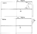
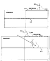
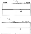
- FIGS. 9A-9H installation and use of the fall arrest assembly during installation/erection of a scaffold platform is shown in accordance with at least some embodiments of the present invention.
- the fall arrest (or erector tie-off) assembly 100/160/186 is installed on the next level 216 above the current completed working level 218.
- One or more fall arrest anchor points are located on an anchor device (e.g., traveler car) that rides along a horizontal member (e.g., rail mechanism) on the assembly.
- the lead erector 222 attaches one of his lanyard hooks 224 to the anchor device.
- each continuous run of the horizontal member e.g., rail mechanism
- the anchor device is designed to traverse the horizontal member from deck to deck. As additional decks are installed end to end in line with the first deck, the horizontal members of each deck can automatically align with each other and allow the anchor device and the worker 222 to traverse the entire length of the deck. In this fashion, the lead erector 222 is continuously tied off to an anchor point, even while traversing the scaffold. If an adjacent assembly is removed, a locking mechanism engages which serves to prohibit the anchor device from becoming detached or otherwise disassembled from the horizontal member at that end.
- the assembly As the worker or erector 222 completes each successive level, including installation of fall protection components (e.g., guard rails, gates, etc.) the assembly is disengaged from its current position and installed on the level above. It is noted that the assembly/installation process can be reversed to accomplish dismantling/disassembly. The assembly will then typically be the last component removed from each successive level and then subsequently installed at the next level down as the scaffold is dismantled.
- fall protection components e.g., guard rails, gates, etc.
- the fall arrest assembly can be installed by a first worker as follows: the first worker first picks up and installs the fall arrestor tie-off plank assembly 100/160/186 on the next level 216 above the current working/completed level 218 on which the first worker 222 is positioned, as shown in FIGS. 9A and 9B . Then, the first worker 222 climbs up to the fall arrestor tie-off plank assembly 100/160/186 by utilizing a scaffold ladder 226, as shown in FIGS. 9C and 9D .
- a safety harness 224 (e.g., lanyard hook) of the first worker 222 is then attached to the traveler car mechanism on the rail assembly of the fall arrestor assembly 100/160/186 for providing a safe walking surface for the worker, as shown in FIG. 9E .
- a second deck structure 228 can be installed.
- the installation of the second deck structure after installation of the current deck structure and the fall arrestor assembly is accomplished as follows: A second worker 230 from another level (e.g., the level 218 below) hands the first worker 222 the second deck 228 as shown in FIG. 9F .
- the second deck 228 is then placed end-to-end in line with the fall arrestor assembly, as shown in FIG. 9G .
- the stop pin mechanism is automatically activated due to the automatic operation of the uplift mechanism, thereby allowing the first worker to move freely along the length of both deck structures while being continuously tied off, as shown in FIG. 9H .
- the aforementioned steps of FIGS. 9A-9H are then repeated for installing additional decks.
- a hands-free, continuous run, fall arrest anchoring assembly can be incorporated into scaffolds, providing automatic, continuous tie-off.
- the fall arrest system or assembly advantageously provides a fall arrest anchor point that allows tying off in advance of a lead erector climbing on a scaffold assembly and/or up to a next level of an assembly.
- the assembly is characterized by an ease use during, for example, both installation and dismantling of a scaffold assembly.
- the present invention is intended to encompass a variety of other features, including various refinements to the existing components.
- deck hooks are employed in the present embodiments for connecting the deck structure 102 to the scaffold tube
- other types of fastening mechanism can be employed.
- any of a variety of hooks having varying configurations, shapes and sizes as may be deemed suitable for securely connecting the deck structure 102 to the scaffold member can be employed as well.
- the size of the deck hooks, and particularly, the engaging portion of the hooks can vary depending upon the diameter of the scaffold member engaged by way of the deck hooks.
- the scaffold tube can have a diameter of 1.90" or 1.69". In other embodiments, the diameter of the scaffold tube can vary.
- the shapes, sizes, configurations, profiles and material of construction of the various components can vary to convenience.
- the shapes and sizes of the stop pin mechanisms can vary. Notwithstanding the fact that a cylindrical or substantially cylindrical stop pin is illustrated in the FIGS. described above, it is nevertheless an intention of this invention to include various shapes of the stop pin including, geometrical and non-geometrical shapes.
- the shape of the deck structure can vary. In other embodiments, a rectangular deck structure need not be employed. Rather, other shapes and sizes as may be deemed suitable depending upon the application and the space constraints for installing a scaffold work platform assembly can be employed.
- size and configuration of other components of the scaffold work platform system can vary depending upon the embodiments and based upon the application.
- corrosion/rust resistant coatings can be provided on various components of the fall arrestor assembly for protecting the surfaces thereof.
- Other types of coating/protectants can be provided as well.
- the fall arrestor assembly with respect to being utilized in a scaffold work platform assembly can be employed in a variety of applications.
- the scaffold assembly can be used in various events including, for example, musical/theatrical events and staging events.
- the scaffold assembly can be employed for supporting and/or carrying a wide variety of equipment.
- the fall arrestor assembly can be temporarily or permanently installed for use with, in conjunction with or as part of the scaffold assembly. Further, the fall arrest assembly need not always be employed as part of a scaffold assembly.
- the fall arrest assembly can be employed for various other purposes including, for example, railway construction wherein the fall arrestor assembly can be connected to the railway tracks for the safety of workers.
- the fall arrest assembly can be put to other uses as well.
Landscapes
- Engineering & Computer Science (AREA)
- Architecture (AREA)
- Mechanical Engineering (AREA)
- Civil Engineering (AREA)
- Structural Engineering (AREA)
- Emergency Lowering Means (AREA)
- Bridges Or Land Bridges (AREA)
- Movable Scaffolding (AREA)
Description
- The present invention relates to scaffold work platform systems and, more particularly, to deck structures and fall arrest mechanisms employed in such scaffold work platform systems.
- When erecting a scaffold, each level is typically completed before moving up to construct the next level. This may involve moving large quantities of scaffold equipment up hundreds of feet horizontally along a level, until that level is completed. A lead erector in a scaffold crew typically has to move along the length of a scaffold prior to installation of fall protection equipment (e.g., guard rails, gates, etc.). Many companies mandate total or 100% tie-off, meaning the erector must have the hook to his fall arrest harness attached to an
anchor point 100% of the time. This can typically be accomplished by using hooks for each harness and hooking each one to an anchor point further down the scaffold run, then returning back and unhooking the first hook from the first anchor point. If the worker neglects to tie off, or ties off to an anchor point that cannot take the load imposed by a fall, the worker is vulnerable to injury. - A lead erector in a scaffold crew typically stands on a scaffold before the installation of any fall protection or arrest devices (e.g., guard rails, gates, etc.). Traditionally, such individuals (e.g., lead erectors) used lanyards hooks attached to fall arrest harnesses or the like to any available (and not necessarily suitable) anchor or securing point. Such anchoring points included the scaffold itself, the building adjacent to which the scaffold was typically positioned, or the like, with the intent being to use this point as a fall arrest anchor. However, buildings may not have suitable anchor points, that is, anchor points that can be accessed from the scaffold itself. Moreover, the scaffold itself is typically not designed to serve as a fall arrest anchor, anchor point, or anchor structure.
- Accordingly, it would be desirable to provide a safe yet convenient to use fall arrest anchoring assembly. Additionally, it would be desirable to provide for an assembly that can be incorporated into scaffolds themselves, providing automatic, continuous tie-off. Ideally, such a fall arrest system or assembly would provide a fall arrest anchor point that could allow tying off in advance of a lead erector climbing on a scaffold assembly, or up to a next level of the assembly. Furthermore, it would be desirable if the assembly were easy to use, for example by providing for easy installation (e.g., during engagement or disengagement of the assembly). It is known from document
FR-A-2 501 267 - In one aspect, the present invention relates to a fall arrest assembly according to claim 1 and also its dependent claims.
In its main aspects it comprises a deck structure and a rail assembly in operable association with the deck structure, the rail assembly permitting an individual to tie-off in a manner that permits the individual with a range of motion along the deck structure while being tied-off. The fall arrest assembly further includes a first uplift hook mechanism connected to or otherwise installed on the deck structure such that the first uplift hook mechanism is employed for both securing the deck structure to and releasing the deck structure from at least one supporting member. - In another aspect, a fall arrest assembly comprising a deck structure is provided. In at least some embodiments, the fall arrest assembly further includes a rail assembly in operable association with the deck structure, which permits an individual to tie-off in a manner that permits the individual with a range of motion along the deck structure. Also provided in the fall arrest assembly is a first uplift hook mechanism connectable to the deck structure for engaging to and/or disengaging from a supporting member. A plurality of deck hooks connectable to or otherwise installed on the deck structure for connecting the deck structure to the supporting member is additionally provided. The fall arrest assembly additionally comprises a deck latch assembly that is connected to the first uplift hook mechanism for facilitating connection of the deck structure to a second deck structure.
- In yet another aspect, a method of installing a fall arrest assembly is provided. The method comprises providing (i) a deck structure; and (ii) a rail assembly in operable association with the deck structure. The method further comprises locating an anchor point on the rail assembly. The method additionally comprises climbing onto the deck structure. Further, the method comprises attaching one or more lanyard mechanisms to the anchor point on the rail assembly to provide a range of movement on the deck structure when erecting a scaffold assembly.
- Various other aspects, objects, features and embodiments of the present invention are disclosed with reference to the following specification, including the drawings.
- Embodiments of the invention are disclosed with reference to the accompanying drawings and are for illustrative purposes only. The invention is not limited in its application to the details of construction or the arrangement of the components illustrated in the drawings. The drawings illustrate a best mode presently contemplated for carrying out the invention. The invention is capable of other embodiments or of being practiced or carried out in other various ways. Like reference numerals are used to indicate like components. In the drawings:
-
FIG. 1 illustrates a perspective view of a fall arrestor assembly in accordance with at least some embodiments of the present invention; -
FIG. 2 illustrates an enlarged perspective view of a portion of the fall arrestor assembly ofFIG. 1 in accordance with at least some embodiments of the present invention; -
FIG. 3 illustrates an enlarged, bottom end view of the underside of the fall arrestor assembly ofFIG. 1 in accordance with at least some embodiments of the present invention; -
FIG. 4 illustrates an enlarged bottom view of a portion of the fall arrestor assembly in accordance with at least some embodiments of the present invention; -
FIG. 5 shows a top view of another embodiment of the fall arrestor assembly in accordance with at least some embodiments of the present invention; -
FIGS. 6A-6C show enlarged sectional views taken along lines "A-A", "B-B" and "C-C" ofFIG. 5 , respectively, and showing portions and specific components of the fall arrestor assembly in accordance with at least some embodiments of the present invention; -
FIG. 7 shows a top view of the fall arrestor assembly in an alternate embodiment in accordance with at least some embodiments of the present invention; -
FIGS. 8A-8E show enlarged sectional views taken along lines "A-A", "B-B", "C-C", "D-D" and an end view ofFIG. 7 , respectively, and showing portions and specific components of the fall arrestor assembly in accordance with at least some embodiments of the present invention; and -
FIGS. 9A-9H illustrate in schematic form, a step-by-step method of installing and/or using the fall arrestor assembly in accordance with at least some embodiments of the present invention. - Referring to
FIG. 1 , a perspective view of a fall arrest tie-off assembly 100 is shown in accordance with at least some embodiments of the present invention. The fall arrest tie-off assembly 100 is also referred herein as a fall arrest anchor assembly, fall arrest/arrestor assembly, arrest/arrestor assembly, a work-access system, erector tie-off plank assembly, erector scaffold deck fall arrest assembly and the like. As shown, thefall arrest assembly 100 includes a deck structure 102 (also referred herein as decking, decking structure, plank and the like) having atop surface 104 and a bottom surface 106 (SeeFIG. 4 ) separated by athickness 108 and bounded byend cap portions bottom surfaces longitudinal corrugations 114 for increasing the strength of the deck structure and for providing a safe walking surface for workers working on thefall arrest assembly 100. - Notwithstanding the fact that the present embodiment illustrates longitudinal corrugations, in other embodiments, any type of corrugations, grilles, webs, lattices, etc. can be provided in one or both of the top and the
bottom surfaces thickness 108 as well. Furthermore, although in some embodiments, thedeck structure 102 can have a hollow core 116, this need not always be the case. Rather, in other embodiments, the deck structure can have a solid core or any other type of core that may be deemed suitable. Additionally, thethickness 108 can vary depending upon the embodiment of the invention based upon, for example, the load handling capability requirements of the scaffold work platform system employing thefall arrest assembly 100. - Further, in the present embodiment, the
deck structure 102 has a length of about 3,05 m or 2,13 m (10' or 7') and a width of about 0,48 m (19") and is constructed out of aluminum (e.g., non-skid extruded aluminum). In some embodiments, when thedeck structure 102 is made out of non-skid extruded aluminum, the weight of the deck structure can be about 18 kg (40 lbs) when the length is about 2,13 m (7') and about 23 kg (50 lbs) when the length is about 3,05 m (10'). Further, in some alternate embodiments, it has been found that the presentfall arrestor assembly 100 can withstand an impact load transmitted to a harness during a fall arrest of up to about 817 kg (1800 lbs). Notwithstanding the aforementioned configuration of thedeck structure 102, it is contemplated that the sizes, shapes and the load bearing/transmitting capabilities of thefall arrestor assembly 100, including thedecking structure 102 can vary without departing from the spirit and scope of the invention. - A plurality of deck hooks 118 are connected or otherwise installed at least partially on the
end cap portions deck structure 102. The deck hooks 118 permit thedeck structure 102 to be supported at each end by a scaffold tube or tube-like component (not shown) of the scaffold work platform system that is typically horizontally-disposed to support the deck structure in a level fashion. In at least some embodiments, the deck hooks 118 are constructed of aluminum (e.g., solid aluminum). By virtue of constructing the deck structure and the deck hooks of aluminum, a light weighted yet strongfall arrest assembly 100 is provided. Nevertheless, in other embodiments, one or both of thedeck structure 102 and the deck hooks 118 can be made of any of a variety of metals, including other rigid materials such as wood. Additionally, the presence of four deck hooks 118 on theend cap portion 110 and three hooks on theend cap portion 112 in the present embodiment is merely exemplary. In other embodiments, any number of deck hooks 118 as may be deemed necessary for securely connecting thedeck structure 102 to the scaffold tube can be employed. - In addition to the deck hooks 118, the
fall arrestor assembly 100 includes an uplift hook orhook mechanism 120 connected at least partially to theend cap 112 and thedeck structure 102 for securing thefall arrestor assembly 100, and particularly the deck structure, to the scaffold tube member. In at least some embodiments of the invention, at least two uplift hook mechanisms are included in thefall arrestor assembly 100 and positioned at opposite ends of thedeck structure 102 to facilitate connection to other fall arrestor assemblies and/or decking structures. Additional details regarding theuplift hook 120 will be provided in regards withFIGS. 2 and3 . - Also provided on the
deck structure 102 is arail assembly 122 for providing a fall arrest system for ensuring the safety of the worker(s) working on thefall arrestor assembly 100, and additionally for arresting the fall should a worker happen to fall. Therail assembly 122 includes arail mechanism 124 disposed on and running lengthwise on thetop surface 104 of thedeck structure 102. Therail assembly 120 including therail mechanism 124 will be described in greater detail inFIG. 2 . A traveler mechanism 117 (also referred herein as traveler, traveler car, car mechanism or traveler car mechanism) can additionally be engaged to, or otherwise fitted over or with respect to therail mechanism 124, in a manner well known, for moving thetraveler 117 in adirection 115 with respect to the rail mechanism. - In at least some embodiments, the
traveler 117 is in rolling engagement with therail mechanism 124. In other embodiments, thetraveler 117 can be an anchor device constructed out of, for example, aluminum, and having ball bearings for mounting and moving the traveler on therail mechanism 124. Notwithstanding the fact that a particular shape, size and configuration of thetraveler 117 is shown, it is nevertheless an intention of this intention to include a variety of traveler mechanisms suitable for anchoring to therail mechanism 124 in a movable manner. - In at least some additional embodiments, the
traveler 117 can have one or more loops 119 (also referred herein as hooks, latch, latching mechanism etc.) for attaching a safety harness (e.g., lanyard - not shown) of a worker to the traveler for arresting motion in the event of a fall of the worker. Typically, theloops 119 can be any of variety of loops that are commonly available and frequently employed in scaffold systems. Further, the positions of theloops 119 on thetraveler 117 can vary. For example, in at least some embodiments, the loops can be positioned on the top surface of the traveler. In other embodiments, theloops 119 can be positioned on a side surface thereof. In yet other embodiments, multiple loops including, for example, one loop on the top surface and one loop on the side surface, can be present, as shown inFIGS. 1 and2 . Additionally, the shape and size of theloops 119 can vary depending upon, for example, the shape and size of the safety harness and lanyard employed for engaging with the loops and the arrangement of the scaffold work platform system. - Therefore, the
traveler 117 provides a mobile anchor device for serving as a latching point (e.g., via the hooks 119) to ensure safety of a worker. It should be understood that the terms moving, rolling, engaging, fitting, etc. are intended to have a broad interpretation and can encompass any of a variety of fit or connection means for providing easy sliding movement along therail mechanism 124 in any direction. Therail assembly 122 additionally includes one or more stops or stop mechanisms 126 (e.g., one or more stop pins), described below, that are in operable association with (e.g., built into) the rail orrail mechanism 124 to limit removal and or travel/motion of thetraveler 117 with respect to the rail mechanism. - Also shown in
FIG. 1 is a deck latch assembly 128 (also referred herein as latch assembly, latch, and the like) that is used for securely connecting onefall arrestor assembly 100 to another fall arrestor assembly. Thedeck latch assembly 128 is shown and described in greater detail with respect toFIG. 4 . As illustrated inFIG. 1 , in at least some embodiments, thedeck latch assembly 128 can generally located in a center or central region of thedeck structure 102 and typically connected to theuplift hook mechanism 120. In at least some embodiments, thedeck latch assembly 128 is connected to both of theuplift hook mechanisms 128, although in other embodiments, the deck latch assembly can be connected to a single uplift hook mechanism as well. In other embodiments, the positioning of thedeck latch assembly 128 can vary. For example, in at least some embodiments, thedeck latch assembly 128 may be positioned at an end of thedeck structure 102. Other positions and orientations of thedeck latch assembly 128 depending upon the arrangements of the scaffold assembly are contemplated and considered within the scope of the invention. - Notwithstanding the configurations, dimensions and profiles of the various components of the
fall arrestor assembly 100 described above, it is an intention of this invention to encompass additional components including various refinements to the previously described components. For example, in other embodiments, various handle structures, support structures etc. can be provided. In alternate embodiments, components other than those described above can be present as well. Further, the shapes, sizes and numbers of the various components of thefall arrestor assembly 100 can vary to convenience. By virtue of providing thefall arrestor assembly 100 having the deck hooks 118, theuplift hook 120 and therail assembly 122, the present invention advantageously provides a work platform system in which thedecking structure 102 can be installed and/or removed conveniently by a single individual, called a "lead erector". - Turning now to
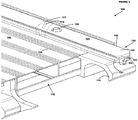
FIG. 2 , an enlarged perspective view of a portion of thefall arrestor assembly 100 ofFIG. 1 is shown, in accordance with at least some embodiments of the present invention. As shown, thefall arrestor assembly 100 includes thedeck structure 102 bounded by the end cap portions 110 (SeeFIG. 1 ) and 112 and further having the plurality of deck hooks 118 for securing the decking to the scaffold structure (e.g., tubular scaffold) of the scaffold work platform system. Also shown is therail assembly 122 in operational association with thedeck structure 102 and including therail mechanism 124 and the stops or stop pin mechanism(s) 126 for limiting removal and/or travel of thetraveler 117 that is in association with the rail mechanism. - With respect to the
rail mechanism 124 in particular, it includes one or more rail, rail-like structures or possibly beams and tracks that are disposed on, or otherwise attached to, thetop surface 104 of thedeck structure 102 at an edge thereof. In at least some embodiments, the rail(s) of therail mechanism 124 can be removably connected to the deck structure by any of a variety of fastening and/or engaging mechanisms in a known manner. In other embodiments, therail mechanism 124 can be integrally formed, in a raised or a recessed portion of the deck structure itself thereby providing a rail or rail-like mechanism for receiving atraveler 117 or other movable tie-off apparatus. Additionally, in some embodiments, therail mechanism 124 can be constructed of steel, although other metal or rigid materials can be employed as well. It should be understood that the shape, size and material of construction of therail mechanism 124 can vary to convenience. Furthermore, the term "rail" is intended to have a broad meaning including any elongate structure to which thetraveler 117 can be attached for sliding/moving along the rail. - Additionally, although in the present embodiment the
rail mechanism 124 is shown to be disposed longitudinally (lengthwise) on thedeck structure 102 at an edge thereof, in other embodiments, the orientation of the rail mechanism can vary. For example, in some embodiments, therail mechanism 124 can be disposed horizontally along the edge of the deck structure. Alternatively, in some embodiments, therail mechanism 124 can be disposed in a central (or substantially central) portion of thedeck structure 102. In alternate embodiments, other orientations are intended to be encompassed within the scope of the invention. Further, therail mechanism 124 can be a separate component that is connected directly or indirectly to the deck structure by any of a variety of engaging or fastening mechanisms. Alternatively, in alternate embodiments, therail mechanism 124 can be integrally formed with thedeck structure 102, or integrated within or with respect to the deck structure itself. - With respect to the structure of the rail(s) (also referred herein as rail-like mechanism, beam or track) in particular, any suitable structure with or without various channels, grooves and contours can be employed. For example, in the present embodiment, the
rail mechanism 124 has first andsecond surfaces top surface 104 of thedeck structure 102, the first and the second surfaces being connected by third and fourth side surfaces 127 and 129, respectively. Further, as shown, one or both of the third and thefourth surfaces grooves 131 for securely fastening thetraveler 117 to therail mechanism 124. In at least some embodiments, the first and thesecond surfaces deck structure 102. By virtue of providing arail mechanism 124 having grooves and channels, thetraveler 117 can be prevented from moving in a direction transverse to the direction of the rail mechanism. Anoptional orifice 133 passing through at least a portion of therail mechanism 124 can be provided in some embodiments to reduce the overall weight of therail assembly 122. Other components including, for example, locking mechanisms for holding thetraveler 117 and theloops 119 in position can additionally be employed. Various other components can also be used in conjunction with, or as part of therail mechanism 124 without departing from the scope of the invention. - Further, as indicated earlier, the stops or stop
pins 126, in accordance with at least some embodiments, move in a vertical fashion when the decking structure is placed and secured with regard to a scaffold assembly in a level horizontal fashion. In this way, the one or more of the stop pins 126 extend and/or retract to limit removal and/or motion of thetraveler 117 that is in association with therail mechanism 124. In at least some embodiments, the stop or stoppins 126 have a default position that is in the extended (stop) position. In other embodiments, it is contemplated that thetraveler 117 to which a harness of an individual (e.g., a lead erector) is connected to arrest a fall, remains between to extendedstop pin mechanisms 126 so as to limit the movement of a traveler car. In alternate embodiments, the one or more stops or stoppins 126 are in an extended (stop) position when the decking orplank structure 102 is not connected to or installed at a given end of thedecking structure 102. In further embodiments, the stops or stoppin mechanisms 126 automatically retract or recede into the rail, for example, below thetop surface 123 of therail mechanism 124 when another decking structure is connected todecking structure 102 in end-to-end fashion, so as to permit an installer to move out onto the next, connected decking structure. And in yet other embodiments, the one or more stops or stoppin mechanisms 126 are to extend once again in, for example, a stop position, when such a second deck is removed from its end-to-end position. - Turning to
FIG. 3 , an enlarged, bottom end view of the bottom surface (or underside) of thedeck structure 102 showing theuplift mechanism 120 and the stop mechanism 126 (SeeFIG. 2 ) in greater detail is shown in accordance with at least some embodiments of the present invention. As shown, in at least some embodiments of the invention, theuplift hook mechanism 120 is located at a central or substantially central portion of thedeck structure 102 substantially in-line with the deck latch assembly 128 (shown inFIG. 4 ). Additionally, theuplift hook mechanism 120 is positioned such that it protrudes from one end of thedeck structure 102 for contacting an underside of the scaffold tube member, which as previously mentioned is typically horizontally disposed with respect to the deck structure. In at least some embodiments, theuplift hook mechanism 120 is connected to thedeck structure 102 viabolts 130 passing through the uplift hook mechanism andstructural element 132. Generally, to accord stability to theuplift hook mechanism 120, a plurality ofstructural elements 132 connecting the uplift hook mechanism to thedeck structure 102 via thebolts 130 are present. For example, in the present embodiment, twostructural elements 132 connecting theuplift hook mechanism 120 to thedeck structure 102 are shown. Nevertheless, in other embodiments, more than two, or potentially a single structural element for connecting the uplift hook mechanisms to thedeck structure 102 can be employed depending upon the length of the deck structure and the dimensions of theuplift hook mechanism 120. - In addition, in at least some embodiments, the
uplift hook mechanism 120 is springloaded such that the uplift hook mechanism can retract as thedeck structure 102 is being installed, and once a deck structure is properly positioned, the hook mechanism can lock into place, thereby securing the decking structure to the scaffold. To enable the uplift hook mechanism to contract and retract by virtue of the spring mechanism without interference from thestructural elements 132, theuplift hook mechanism 120 is provided withslots 134 through which the structural elements are connected to the uplift hook mechanism. It can further be appreciated that although a singleuplift hook mechanism 120 is shown inFIG.3 , multiple uplift hooks mechanisms, having similar or substantially similar configurations and orientations to theuplift hook mechanism 120 described above, can be present in other embodiments. When two suchuplift hook mechanisms 120 are utilized (e.g., at each end of the deck structure 102), it is contemplated that the uplift hook mechanisms are both locked (e.g., in some embodiments, in an extended position) under the scaffold (e.g., scaffold header) to secure the deck structure to the scaffold. - Also shown in
FIG. 3 is a stop pin assembly 136, which is used to actuate the stop mechanism 126 (SeeFIGS. 1 and2 ). The stop pin assembly 136 includes a stoppin plunger mechanism 138, which actuates thestop pin mechanism 126 when thedeck structure 102 is connected to or disassembled from another deck structure. The stop pin assembly 136 further includes a stoppin guide mechanism 140 for guiding thestop pin mechanism 126 during extension and retraction. The stop pin assembly 136 including the stoppin plunger mechanism 138 and the stoppin guide mechanism 140 is attached in operational association with thebottom surface 106 of thedeck structure 102 viabracket 142 andbolt 144. Notwithstanding the particular arrangement of the stop pin assembly 136 described above, in other embodiments, the arrangement and configuration of the various components of the stop pin assembly can vary. - Turning now to
FIG. 4 , an enlarged bottom view of a portion of thefall arrestor assembly 100 showing thedeck latch assembly 128 including various associated components/features is shown in accordance with at least some embodiments of the present invention. Thedeck latch assembly 128 comprises alatch mechanism 146, a pair ofshackle mechanisms 148, apull rod mechanism 150 and anaxle 152. Thelatch mechanism 146 includes, as shown, a recessed/slottedcam profile 154 on each of its sides so as to receive or accept pins or pin-like mechanisms 156 on one end (and for connecting) eachshackle mechanism 148. Additionally, thelatch mechanism 146 is rotatable, such that when so rotated, thepins 156 in theshackle mechanisms 148 are pulled in a direction that is, as illustrated, towards the center of thedecking structure 102. The directions of movement are indicated byarrows 158 and the center of the decking structure is indicated by axis C (with dashed lines). Thepull rod mechanism 150 is used to disengage the uplift hook mechanism(s) 128 (shown inFigs. 1 and3 ). Such engagement and disengagement of two deck structures causes the stop pin mechanisms 126 (shown, for example, inFig. 2 ) to extend and/or retract as previously described. Therefore, the horizontal motion of thepull rod mechanism 150 is translated into a vertical motion of thestop pin mechanisms 126 for providing a continuous run, automatic and hands-freefall erector assembly 100. It should be understood that variations, such as the placement of thedeck latch assembly 128, can vary to convenience and such variations are contemplated and considered within the scope of the present invention. - Notwithstanding the fact that in some embodiments, a recessed/slotted
cam profile 154 for actuation of thelatch mechanism 146 is provided, in other embodiments, other means/mechanisms for actuation/retraction of the latch mechanism can be employed as well. For example, in at least some embodiments, a rotatble drum, the rotation of which produces tension in theshackle mechanism 148 and thepull rod mechanism 150 to actuate the uplift hooks mechanism(s) 128, can be utilized. In alternate embodiments, other types of devices for actuating the uplift hooks mechanism(s) 128 can be employed without departing from the spirit and scope of the present invention. Additionally, theshackle mechanism 148 and thepull rod mechanism 150 can all vary in other embodiments. For example, in other embodiments, various other types of devices and structures achieving substantially similar functionality as theshackle mechanism 148 and thepull rod mechanism 150 can be utilized for extending/retracting the uplift hook mechanism(s) 128 by actuating the recessed/slottedcam profile 154 or other suitable device. - Referring now to
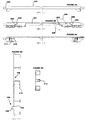
FIG. 5 , a top view of another fall arrestor assembly 160 (also called an "erector tie-off assembly") is shown in accordance with at least some embodiments of the present invention.FIGS. 6A-6C show enlarged sectional views taken along lines "A-A", "B-B" and "C-C" ofFIG. 5 , respectively, and showing portions and specific components of thefall arrest assembly 160. Referring toFIGS. 5 and6A-6C , thefall arrestor assembly 160 includes a deck ordecking structure 162 having a plurality of decking ordeck hook mechanisms 164 disposed on its ends that permit theassembly 160 to be supported by scaffold mechanisms (e.g., scaffold tubes). Arail assembly 166 having a rail orrail mechanism 168 runs lengthwise along the deck. As indicated earlier, any of a variety of rails, rail-like mechanisms and beams, each with or without various grooves and channels can be employed. A traveler car (not shown) can be connected to therail 168 for moving along or on top of the rail (e.g., by rolling engagement), and a scaffold worker (e.g., lead erector) can then connect (e.g., tie-off) a safety harness to the traveler car. By virtue of connecting the traveler car to therail mechanism 168, the present invention provides an erector assembly that permits a wide range of movement on thedeck structure 162 when building a scaffold. - Further, as indicated previously, the range of motion of the traveler car is only limited or constricted by one or more of the
stop pin assemblies 170. In at least some embodiments, thestop pin assemblies 170 include stop pins or stoppin mechanisms 172, which serve to physically stop the travel car (again not shown) from moving past a given location of the stop pin, for example when, as described above, the stop pins are in an extended position. Thestop pin assemblies 170 each further include an activation switch oractivation switch mechanism 174. As shown, at least in part, inFIG. 6B , when theerector assembly 160, and specifically the deck hooks 164 of thedecking structure 162 are connected with and supported by ascaffold member 176, activation switches 174 are used to activate or actuate thestop pin mechanisms 172. For example, and in accordance with at least some embodiments, when so positioned, theactivation switch 174 can cause thestop pin mechanism 172 to automatically retract and thus permit the traveler car to have its range of motion extended to the adjacent decking structure/assembly. Alternatively, when removed from such a position relative to scaffoldsupport 176, theactivation mechanism 174 can be used to automatically extend thestop pin mechanism 172, thereby limiting the range of motion of the traveler care. - A handle or handle
mechanism 178 can also be provided in some embodiments of the present invention. In some of these embodiments having the handle, the handle can be provided in a location that is centrally-disposed on thedeck structure 162. In other embodiments, thehandle 178 can be disposed on one end of thedeck structure 162, as shown inFIG. 5 . In alternate embodiments, the position of thehandle 178 can vary. Thehandle 178 is connected to, as shown, to a pair of uplift hooks or uplifthook mechanisms 180, via activation cable orcables 182. With additional reference toFigs. 6A and 6C , and as noted above with respect to a previous embodiment(s), rotation of thehandle 178, indicated byrotational arrows 184, creates necessary tension on the activation cable(s) 182 to moveuplift hook mechanisms 180. Such movement provides for the securing (e.g., during assembly) or separation of (e.g., during dismantling) of theuplift hook mechanisms 180 with respect to the supporting scaffold member(s) 176. In alternative embodiments, it is also contemplated that thehandle 178 may be attached to a rotating cylinder or spool mechanism (not shown) to accomplish actuation or movement of the uplift hook mechanism(s) 180. Advantageously, the size and location of thehandle mechanism 178 and the presence of theactivation switch 174 permits a single erector to accomplish this activity and, typically, in single-handed fashion. - Referring now to
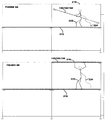
FIG. 7 an alternate embodiment of afall arrest assembly 186 is shown in accordance with at least some embodiments of the present invention.FIGS. 8A-8E show enlarged sectional views taken along lines "A-A", "B-B", "C-C", "D-D" and an end portion ofFIG. 7 , respectively, and showing portions and specific components of thefall arrest assembly 186. Referring toFIGS. 7 and8A-8E , the fall arrest assembly includes adeck structure 188 having a plurality of decking ordeck hook mechanisms 190 disposed on its ends that permit theassembly 188 to be supported by scaffold mechanisms (e.g., scaffold tubes). The deck structure additionally includes a rail mechanism 192 that is integrally formed with the deck structure. - As further shown in
FIG. 8D , the rail mechanism 192 is disposed on a raisedsurface 194 of thedeck structure 188 resulting in adeck portion 196 and arail portion 198. In at least some other embodiments, thesurface 194 of thedeck structure 188 can be formed within a recess of the deck structure such that therail mechanism 190 is disposed on thesurface 194 within the recess. Additionally, therail mechanism 190 can run lengthwise along thedeck structure 188. Other orientations of therail mechanism 190 are also contemplated and considered within the scope of the invention. Further, as indicated earlier, any of a variety of rails, rail-like mechanisms and beams, each with or without various grooves and channels can be employed. A traveler car (not shown) can be connected to therail 190 for moving along or on top of the rail (e.g., by rolling engagement), and a scaffold worker (e.g., lead erector) can then connect (e.g., tie-off) a safety harness to the traveler car. By virtue of connecting the traveler car to therail mechanism 190, the present invention provides an erector assembly that permits a wide range of movement on thedeck structure 188 when building a scaffold. - Additionally, as shown in
FIG. 7 andFIGS. 8A-8E , thefall arrest assembly 186 includes one or moreuplift hook mechanisms 200 that are connected to each other viahandle 202 and wire/activation cable 204. Upon activating thehandle 202 by rotating in a direction illustrated byarrows 206, the uplift hook mechanisms are activated in a direction depicted byarrows 208 to attach or release thefall arrest assembly 186 to/from other deck structures. The activation of thehandle 202 and theuplift hook mechanism 200 is similar in operation to that described above with respect toFIGS. 5 and6A-6C . One or more stops or stoppin mechanisms 210 activated by one or more activation switches 212 can additionally be provided for use in conjunction with therail mechanism 190 for limiting the travel of the traveler. Also shown inFIGS. 8D and 8E is ahousing 214 for holding the various components of thefall arrest assembly 186. Additional components described above can also be present in thefall arrest assembly 186, with the structure and operation of those components closely mimicking the structure and operation of the components described above. - Turning now to
FIGS. 9A-9H , installation and use of the fall arrest assembly during installation/erection of a scaffold platform is shown in accordance with at least some embodiments of the present invention. As shown, the fall arrest (or erector tie-off)assembly 100/160/186 is installed on thenext level 216 above the current completed workinglevel 218. One or more fall arrest anchor points are located on an anchor device (e.g., traveler car) that rides along a horizontal member (e.g., rail mechanism) on the assembly. Upon moving up to the next level, thelead erector 222 attaches one of his lanyard hooks 224 to the anchor device. There are stops located at the end of each continuous run of the horizontal member (e.g., rail mechanism) that serve to prevent the device from disengaging from the horizontal member. The anchor device is designed to traverse the horizontal member from deck to deck. As additional decks are installed end to end in line with the first deck, the horizontal members of each deck can automatically align with each other and allow the anchor device and theworker 222 to traverse the entire length of the deck. In this fashion, thelead erector 222 is continuously tied off to an anchor point, even while traversing the scaffold. If an adjacent assembly is removed, a locking mechanism engages which serves to prohibit the anchor device from becoming detached or otherwise disassembled from the horizontal member at that end. As the worker orerector 222 completes each successive level, including installation of fall protection components (e.g., guard rails, gates, etc.) the assembly is disengaged from its current position and installed on the level above. It is noted that the assembly/installation process can be reversed to accomplish dismantling/disassembly. The assembly will then typically be the last component removed from each successive level and then subsequently installed at the next level down as the scaffold is dismantled. - Therefore, the fall arrest assembly can be installed by a first worker as follows: the first worker first picks up and installs the fall arrestor tie-
off plank assembly 100/160/186 on thenext level 216 above the current working/completedlevel 218 on which thefirst worker 222 is positioned, as shown inFIGS. 9A and 9B . Then, thefirst worker 222 climbs up to the fall arrestor tie-off plank assembly 100/160/186 by utilizing a scaffold ladder 226, as shown inFIGS. 9C and 9D . A safety harness 224 (e.g., lanyard hook) of thefirst worker 222 is then attached to the traveler car mechanism on the rail assembly of thefall arrestor assembly 100/160/186 for providing a safe walking surface for the worker, as shown inFIG. 9E . Subsequently a second deck structure 228 can be installed. Typically, the installation of the second deck structure after installation of the current deck structure and the fall arrestor assembly is accomplished as follows: A second worker 230 from another level (e.g., thelevel 218 below) hands thefirst worker 222 the second deck 228 as shown inFIG. 9F . The second deck 228 is then placed end-to-end in line with the fall arrestor assembly, as shown inFIG. 9G . By virtue of installing the second deck structure in line with the current deck structure by way of the deck hooks, the stop pin mechanism is automatically activated due to the automatic operation of the uplift mechanism, thereby allowing the first worker to move freely along the length of both deck structures while being continuously tied off, as shown inFIG. 9H . The aforementioned steps ofFIGS. 9A-9H are then repeated for installing additional decks. - Accordingly, provided herein is a hands-free, continuous run, fall arrest anchoring assembly. The assembly can be incorporated into scaffolds, providing automatic, continuous tie-off. The fall arrest system or assembly advantageously provides a fall arrest anchor point that allows tying off in advance of a lead erector climbing on a scaffold assembly and/or up to a next level of an assembly. By providing for or permitting single-handed operation, as well as other attributes that have been described or are apparent, the assembly is characterized by an ease use during, for example, both installation and dismantling of a scaffold assembly.
- Notwithstanding the embodiments of the
fall arrestor assembly 100 shown and described with respect toFIGS. 1-6C , the present invention is intended to encompass a variety of other features, including various refinements to the existing components. For example, although deck hooks are employed in the present embodiments for connecting thedeck structure 102 to the scaffold tube, in other embodiments, other types of fastening mechanism can be employed. Relatedly, any of a variety of hooks having varying configurations, shapes and sizes as may be deemed suitable for securely connecting thedeck structure 102 to the scaffold member can be employed as well. For example, the size of the deck hooks, and particularly, the engaging portion of the hooks can vary depending upon the diameter of the scaffold member engaged by way of the deck hooks. In at least some embodiments, the scaffold tube can have a diameter of 1.90" or 1.69". In other embodiments, the diameter of the scaffold tube can vary. - Furthermore, the shapes, sizes, configurations, profiles and material of construction of the various components can vary to convenience. For example, the shapes and sizes of the stop pin mechanisms can vary. Notwithstanding the fact that a cylindrical or substantially cylindrical stop pin is illustrated in the FIGS. described above, it is nevertheless an intention of this invention to include various shapes of the stop pin including, geometrical and non-geometrical shapes. Similarly, the shape of the deck structure can vary. In other embodiments, a rectangular deck structure need not be employed. Rather, other shapes and sizes as may be deemed suitable depending upon the application and the space constraints for installing a scaffold work platform assembly can be employed. Relatedly, size and configuration of other components of the scaffold work platform system can vary depending upon the embodiments and based upon the application.
- Additionally, corrosion/rust resistant coatings can be provided on various components of the fall arrestor assembly for protecting the surfaces thereof. Other types of coating/protectants can be provided as well. Further, the fall arrestor assembly with respect to being utilized in a scaffold work platform assembly can be employed in a variety of applications. For example, the scaffold assembly can be used in various events including, for example, musical/theatrical events and staging events. In other embodiments, the scaffold assembly can be employed for supporting and/or carrying a wide variety of equipment. Additionally, the fall arrestor assembly can be temporarily or permanently installed for use with, in conjunction with or as part of the scaffold assembly. Further, the fall arrest assembly need not always be employed as part of a scaffold assembly. Rather, in at least some embodiments, the fall arrest assembly can be employed for various other purposes including, for example, railway construction wherein the fall arrestor assembly can be connected to the railway tracks for the safety of workers. In alternate embodiments, the fall arrest assembly can be put to other uses as well.
- It is specifically intended that the present invention not be limited to the embodiments and illustrations contained herein, but include modified forms of those embodiments including portions of the embodiments and combinations of elements of different embodiments as come within the scope of the following claims.
Claims (17)
- A fall arrest assembly (100) comprising:a deck structure (102);a rail assembly (122) in operable association with the deck structure, the rail assembly permitting an individual to tie-off in a manner that permits the individual with a range of motion along the deck structure while being tied-off, the rail assembly further comprising a rail mechanism; and one or more stop pin assemblies, each stop pin assembly comprising a pin or pin-like mechanism positioned with respect to or in operable association with the rail mechanism; anda first uplift hook mechanism (120) connected to or otherwise installed on the deck structure, the first uplift hook mechanism for both securing the deck structure to and releasing the deck structure from at least one supporting member,wherein the pin or pin-like mechanism of the rail mechanism can extend and/or retract to limit removal and/or travel of a traveler that is in association with the rail, each stop pin assembly further comprising a stop pin plunger mechanism for actuating the stop pin mechanism when the deck structure is connected to or disassembled from another deck structure; and a stop pin guide mechanism for guiding the stop pin mechanism during extension and retraction thereof, so that the extension and/or retraction of the pin or pin-like mechanism provides a continuous, automatic and hands-free fall arrestor system.
- The assembly of Claim 1, wherein each stop pin assembly further comprises: an activation switch mechanism, wherein the activation switch mechanism can be used to activate or actuate the pin or pin-like mechanism.
- The assembly of Claim 1 or 2, wherein the rail mechanism includes a rail or rail-like structure extending along a longitudinal length of the deck structure that is at least one of integrated within and integrally formed with the surface of the deck structure.
- The assembly of Claim 3, wherein the rail mechanism includes a rail or rail-like structure extending along a longitudinal length of the deck structure that is disposed on a surface of the deck structure.
- The assembly of Claim 1 further comprising a deck latch assembly (128) located in a central or substantially central region of the deck structure and connected to the first uplift hook mechanism (120) for facilitating connection of the deck structure to a second deck structure.
- The assembly of Claim 5, wherein the deck latch assembly (128) further comprises:a pair of shackle mechanisms (148), each shackle mechanism having at least one pin or pin-like mechanism;a latch mechanism (146) having a recessed cam profile on each of its sides so as to receive the respective at least one pin or pin-like mechanism for connecting the pair of shackle mechanisms to the latch mechanism;a pull rod mechanism having a pair of pull rods, each pull rod connected to a respective one of the pair of shackle mechanisms for engaging/disengaging the first uplift hook mechanism from the second deck structure; andan axle in operable association with the latch mechanism for operating the deck latch assembly.
- The assembly of Claim 6, wherein the latch mechanism is rotatable, and when so rotated, each of the at least one pin or pin-like mechanism of the respective pair of shackle mechanisms and the pull rod mechanism is pulled along the respective recessed cam profile in a direction that is at least towards a centralized region of the deck structure.
- The assembly of Claim 1, wherein the at least one supporting member is a scaffold member; and
wherein the fall arrest assembly is used in the construction of a scaffold assembly. - The fall arrest assembly (100) of claim 1, wherein it comprises:a deck structure (102);a rail assembly (122) in operable association with the deck structure, the rail assembly permitting an individual to tie-off in a manner that permits the individual with a range of motion along the deck structure while being tied-off; the rail assembly further comprising a rail mechanism; and one or more stop pin assemblies, each stop pin assembly comprising a pin or pin-like mechanism positioned with respect to or in operable association with the rail mechanism;a first uplift hook mechanism (120) connected to the deck structure, the first uplift hook mechanism for engaging to and/or disengaging from a supporting member;a plurality of deck hooks connectable to or otherwise installed on the deck structure for connecting the deck structure to the supporting member; anda deck latch assembly connected to the first uplift hook mechanism for facilitating connection of the deck structure to a second deck structure, wherein the pin or pin-like mechanism of the rail mechanism can extend and/or retract to limit removal and/or travel of a traveler that is in association with the rail, each stop pin assembly further comprising a stop pin plunger mechanism for actuating the stop pin mechanism when the deck structure is connected to or disassembled from another deck structure; and a stop pin guide mechanism for guiding the stop pin mechanism during extension and retraction thereof, so that the extension and/or retraction of the pin or pin-like mechanism provides a continuous, automatic and hands-free fall arrestor system.
- The assembly of Claim 9, further comprising a handle mechanism connected to the first uplift hook mechanism via at least one cable or cable-like device, and wherein rotation of the handle mechanism creates tension on the at least one device to move the first uplift hook mechanism so as to secure and/or separate the first uplift hook mechanism with respect to a supporting scaffold member.
- The assembly of Claim 9 further comprising a second uplift hook mechanism connected to the deck latch assembly, wherein the first and the second uplift hook mechanisms are positioned at opposite ends of the deck structure to facilitate connection to other deck structures;
wherein the first and the second uplift hook mechanisms are spring loaded; and wherein the deck latch assembly is located in a central or substantially central region of the deck structure. - The assembly of Claim 9,
wherein a traveler can be connected to the rail mechanism for moving along or on top of the rail mechanism so that a scaffold worker can connect to the traveler and be provided with a range of movement on the deck structure when erecting a scaffold assembly. - The assembly of Claim 9, wherein the supporting member is a scaffold member.
- The assembly of Claim 9, wherein at least one of the deck structure and the plurality of deck hooks is constructed of aluminum.
- A method of installing a fall arrest assembly, the method comprising:providing a fall arrest assembly according to claim 1 with (i) a deck structure; and (ii) a rail assembly in operable association with the deck structure, the rail assembly being further provided with one or more stop pin mechanisms that are capable of extension and retraction for providing a continuous, automatic and hands-free fall arrest assembly;locating an anchor point on the rail assembly;climbing onto the deck structure; andattaching one or more lanyard mechanisms to the anchor point on the rail assembly for providing a range of movement on the deck structure when erecting a scaffold assembly.
- The method of Claim 15, further comprises:providing a first uplift hook mechanism connected to the deck structure; andconnecting the first uplift hook mechanism with at least one scaffold member of the scaffold assembly for both securing the deck structure to and releasing the deck structure from the at least one scaffold member of the scaffold assembly.
- The method of Claim 15, further comprising: providing one or more deck hook mechanisms connected to the deck structure for connecting the deck structure to the scaffold assembly;
Applications Claiming Priority (2)
| Application Number | Priority Date | Filing Date | Title |
|---|---|---|---|
| US90931607P | 2007-03-30 | 2007-03-30 | |
| PCT/US2008/058720 WO2008121854A1 (en) | 2007-03-30 | 2008-03-28 | Erector scaffold deck fall arrest assembly |
Publications (2)
| Publication Number | Publication Date |
|---|---|
| EP2132387A1 EP2132387A1 (en) | 2009-12-16 |
| EP2132387B1 true EP2132387B1 (en) | 2017-11-22 |
Family
ID=39684293
Family Applications (1)
| Application Number | Title | Priority Date | Filing Date |
|---|---|---|---|
| EP08744650.6A Active EP2132387B1 (en) | 2007-03-30 | 2008-03-28 | Erector scaffold deck fall arrest assembly |
Country Status (9)
| Country | Link |
|---|---|
| US (1) | US9416552B2 (en) |
| EP (1) | EP2132387B1 (en) |
| CN (1) | CN101680231B (en) |
| AU (1) | AU2008232642B2 (en) |
| BR (1) | BRPI0808589B8 (en) |
| CA (1) | CA2681654C (en) |
| ES (1) | ES2660175T3 (en) |
| MX (1) | MX2009010414A (en) |
| WO (1) | WO2008121854A1 (en) |
Families Citing this family (12)
| Publication number | Priority date | Publication date | Assignee | Title |
|---|---|---|---|---|
| CA2531430C (en) * | 2005-12-23 | 2013-10-08 | Etobicoke Ironworks Limited | Scaffold deck and self-locking hook |
| US20140318895A1 (en) * | 2013-04-29 | 2014-10-30 | John Birk | Adjustable length scaffolding and method therefor |
| FR3021985B1 (en) * | 2014-06-05 | 2018-05-25 | Alphi | CONNECTING DEVICE WITH IMPROVED STABILITY |
| CN107476599A (en) * | 2017-07-27 | 2017-12-15 | 中国建筑第八工程局有限公司 | Tile type overlaps packway and its construction method |
| FR3074157B1 (en) * | 2017-11-24 | 2019-11-22 | Jcdecaux Sa | REMOVABLE EQUIPMENT ACCESS FOR INTERVENTION ON PANEL HEIGHT |
| MX2021007206A (en) * | 2018-12-17 | 2021-12-15 | Terex South Dakota Inc | Access deck assembly and handle assembly for an aerial work platform of a vehicle. |
| CN115176061A (en) * | 2019-09-11 | 2022-10-11 | 澳德菲尔控股有限公司 | Scaffold deck, deck element and components thereof |
| US11053694B1 (en) | 2019-12-19 | 2021-07-06 | Robert B. Jordan, IV | Deck rejuvenation system and method |
| USD1017832S1 (en) * | 2020-07-17 | 2024-03-12 | Global Engineers Investment Singapore Pte. Ltd. | Tower |
| DE102021130655A1 (en) | 2021-11-23 | 2023-05-25 | Alfix Gmbh | Deck securing element, scaffolding and method for securing scaffolding decks against lifting |
| DE202023105452U1 (en) | 2023-09-19 | 2023-09-28 | Alfix Gmbh | Deck securing element and scaffolding herewith |
| CN117967021B (en) * | 2024-04-01 | 2024-06-04 | 福建省二建建设集团有限公司 | Safety construction scaffold with multifunctional protection function |
Family Cites Families (15)
| Publication number | Priority date | Publication date | Assignee | Title |
|---|---|---|---|---|
| US3124082A (en) * | 1964-03-10 | Track interlock and safety stop means | ||
| US2040080A (en) * | 1933-08-23 | 1936-05-12 | Howard D Colman | Overhead door |
| US3349720A (en) * | 1966-01-11 | 1967-10-31 | David R Pender | Ski lift |
| FR2501267A1 (en) * | 1981-03-03 | 1982-09-10 | Entrepose | Load platform for scaffolding - comprises panels with longitudinal edges held together by co-operating fastenings |
| GB2158497B (en) * | 1984-01-28 | 1987-06-10 | Rose Edward | Platform structure method of assembling a platform and fitting for use in the method |
| JPH01187257A (en) | 1988-01-22 | 1989-07-26 | Nippon Shokubai Kagaku Kogyo Co Ltd | Scaffolding plate for construction work and bearing member thereof |
| JPH02149050U (en) * | 1989-05-22 | 1990-12-18 | ||
| US5141078A (en) * | 1991-10-10 | 1992-08-25 | Aluma Systems Corp. | Scaffold deck |
| US5279193A (en) * | 1993-02-26 | 1994-01-18 | Emerson Electric Co. | Scaffold deck |
| JPH094216A (en) | 1995-06-23 | 1997-01-07 | Tatsuo Ono | Scaffolding board |
| TW277087B (en) * | 1995-04-14 | 1996-06-01 | Tatsuo Ono | Scaffolding planks |
| US5762441A (en) * | 1996-05-17 | 1998-06-09 | Safway Steel Products, Inc. | End cap system for scaffolding planks |
| CN2276957Y (en) * | 1996-11-29 | 1998-03-25 | 张哲壳 | Scaffolding horizontal treads |
| US6408587B2 (en) * | 1999-12-24 | 2002-06-25 | Total Fabrications Limited | Structural members and associated parts |
| US6520290B1 (en) * | 2000-04-17 | 2003-02-18 | Charles L. Carter | Fall protection method and apparatus |
-
2008
- 2008-03-28 CN CN2008800178632A patent/CN101680231B/en active Active
- 2008-03-28 MX MX2009010414A patent/MX2009010414A/en active IP Right Grant
- 2008-03-28 CA CA2681654A patent/CA2681654C/en active Active
- 2008-03-28 US US12/530,741 patent/US9416552B2/en active Active
- 2008-03-28 AU AU2008232642A patent/AU2008232642B2/en not_active Ceased
- 2008-03-28 EP EP08744650.6A patent/EP2132387B1/en active Active
- 2008-03-28 WO PCT/US2008/058720 patent/WO2008121854A1/en not_active Ceased
- 2008-03-28 BR BRPI0808589A patent/BRPI0808589B8/en active IP Right Grant
- 2008-03-28 ES ES08744650.6T patent/ES2660175T3/en active Active
Also Published As
| Publication number | Publication date |
|---|---|
| BRPI0808589A8 (en) | 2016-05-31 |
| WO2008121854A1 (en) | 2008-10-09 |
| CN101680231A (en) | 2010-03-24 |
| AU2008232642A1 (en) | 2008-10-09 |
| US20100089693A1 (en) | 2010-04-15 |
| EP2132387A1 (en) | 2009-12-16 |
| CA2681654C (en) | 2015-07-21 |
| US9416552B2 (en) | 2016-08-16 |
| CA2681654A1 (en) | 2008-10-09 |
| BRPI0808589B8 (en) | 2019-10-22 |
| CN101680231B (en) | 2012-07-04 |
| AU2008232642B2 (en) | 2014-11-27 |
| MX2009010414A (en) | 2010-03-25 |
| BRPI0808589A2 (en) | 2014-08-05 |
| HK1140528A1 (en) | 2010-10-15 |
| BRPI0808589B1 (en) | 2018-12-11 |
| ES2660175T3 (en) | 2018-03-21 |
Similar Documents
| Publication | Publication Date | Title |
|---|---|---|
| US9416552B2 (en) | Erector scaffold deck fall arrest assembly | |
| US20100126801A1 (en) | Fall arrest apparatus | |
| US10060146B2 (en) | I-beam-attachable lifeline system | |
| CN103492649B (en) | Suspended Scaffolding System | |
| US20050072628A1 (en) | Hanging scaffold support | |
| US8997926B2 (en) | Scaffold fall protection system | |
| US9133632B2 (en) | Platform support device for lifting loads or persons the height of a structure | |
| US20050189171A1 (en) | Safety system and method of use for high workers | |
| US20240044156A1 (en) | Climbing boot for a rail-guided climbing system | |
| US7992679B2 (en) | Anchor system for personal belay safety lines | |
| CA2647576C (en) | Traveling fall protection system | |
| KR20080075624A (en) | Safety scaffolding to prevent the fall of the construction lift | |
| EP2031150A2 (en) | Scaffolding stairway system | |
| US12116793B2 (en) | Scaffolding systems and a scaffolding joint therefor | |
| CA2644824A1 (en) | Fall arrest apparatus | |
| HK1140528B (en) | Erector scaffold deck fall arrest assembly | |
| GB2357112A (en) | Safety line system | |
| CN223675155U (en) | Tensioning construction system for steel-concrete composite tied arch bridges | |
| AU2012200673A1 (en) | Barrier | |
| RU2826417C1 (en) | Safety system for lifting and lowering person, comprising rigid anchor line | |
| CN211421800U (en) | Lower operating platform for hanging basket | |
| RU2275481C1 (en) | Device to perform repair and construction works, particularly on ceilings and areas near the ceilings, and method of device usage | |
| RU2307064C2 (en) | Device for mounting of load by means of flying vehicle | |
| GB2360316A (en) | Suspended scaffold system with stabilising restraint wire | |
| CN121654236A (en) | Communication tower overhauls fixed station subassembly |
Legal Events
| Date | Code | Title | Description |
|---|---|---|---|
| PUAI | Public reference made under article 153(3) epc to a published international application that has entered the european phase |
Free format text: ORIGINAL CODE: 0009012 |
|
| 17P | Request for examination filed |
Effective date: 20090929 |
|
| AK | Designated contracting states |
Kind code of ref document: A1 Designated state(s): AT BE BG CH CY CZ DE DK EE ES FI FR GB GR HR HU IE IS IT LI LT LU LV MC MT NL NO PL PT RO SE SI SK TR |
|
| DAX | Request for extension of the european patent (deleted) | ||
| 17Q | First examination report despatched |
Effective date: 20150312 |
|
| STAA | Information on the status of an ep patent application or granted ep patent |
Free format text: STATUS: EXAMINATION IS IN PROGRESS |
|
| GRAP | Despatch of communication of intention to grant a patent |
Free format text: ORIGINAL CODE: EPIDOSNIGR1 |
|
| STAA | Information on the status of an ep patent application or granted ep patent |
Free format text: STATUS: GRANT OF PATENT IS INTENDED |
|
| INTG | Intention to grant announced |
Effective date: 20170720 |
|
| GRAS | Grant fee paid |
Free format text: ORIGINAL CODE: EPIDOSNIGR3 |
|
| GRAA | (expected) grant |
Free format text: ORIGINAL CODE: 0009210 |
|
| STAA | Information on the status of an ep patent application or granted ep patent |
Free format text: STATUS: THE PATENT HAS BEEN GRANTED |
|
| AK | Designated contracting states |
Kind code of ref document: B1 Designated state(s): AT BE BG CH CY CZ DE DK EE ES FI FR GB GR HR HU IE IS IT LI LT LU LV MC MT NL NO PL PT RO SE SI SK TR |
|
| REG | Reference to a national code |
Ref country code: GB Ref legal event code: FG4D |
|
| REG | Reference to a national code |
Ref country code: CH Ref legal event code: EP |
|
| REG | Reference to a national code |
Ref country code: IE Ref legal event code: FG4D |
|
| REG | Reference to a national code |
Ref country code: AT Ref legal event code: REF Ref document number: 948554 Country of ref document: AT Kind code of ref document: T Effective date: 20171215 |
|
| REG | Reference to a national code |
Ref country code: DE Ref legal event code: R096 Ref document number: 602008053060 Country of ref document: DE |
|
| REG | Reference to a national code |
Ref country code: FR Ref legal event code: PLFP Year of fee payment: 11 |
|
| REG | Reference to a national code |
Ref country code: NL Ref legal event code: FP |
|
| REG | Reference to a national code |
Ref country code: ES Ref legal event code: FG2A Ref document number: 2660175 Country of ref document: ES Kind code of ref document: T3 Effective date: 20180321 |
|
| REG | Reference to a national code |
Ref country code: LT Ref legal event code: MG4D |
|
| REG | Reference to a national code |
Ref country code: AT Ref legal event code: MK05 Ref document number: 948554 Country of ref document: AT Kind code of ref document: T Effective date: 20171122 |
|
| PG25 | Lapsed in a contracting state [announced via postgrant information from national office to epo] |
Ref country code: FI Free format text: LAPSE BECAUSE OF FAILURE TO SUBMIT A TRANSLATION OF THE DESCRIPTION OR TO PAY THE FEE WITHIN THE PRESCRIBED TIME-LIMIT Effective date: 20171122 Ref country code: SE Free format text: LAPSE BECAUSE OF FAILURE TO SUBMIT A TRANSLATION OF THE DESCRIPTION OR TO PAY THE FEE WITHIN THE PRESCRIBED TIME-LIMIT Effective date: 20171122 Ref country code: NO Free format text: LAPSE BECAUSE OF FAILURE TO SUBMIT A TRANSLATION OF THE DESCRIPTION OR TO PAY THE FEE WITHIN THE PRESCRIBED TIME-LIMIT Effective date: 20180222 Ref country code: LT Free format text: LAPSE BECAUSE OF FAILURE TO SUBMIT A TRANSLATION OF THE DESCRIPTION OR TO PAY THE FEE WITHIN THE PRESCRIBED TIME-LIMIT Effective date: 20171122 |
|
| PG25 | Lapsed in a contracting state [announced via postgrant information from national office to epo] |
Ref country code: GR Free format text: LAPSE BECAUSE OF FAILURE TO SUBMIT A TRANSLATION OF THE DESCRIPTION OR TO PAY THE FEE WITHIN THE PRESCRIBED TIME-LIMIT Effective date: 20180223 Ref country code: AT Free format text: LAPSE BECAUSE OF FAILURE TO SUBMIT A TRANSLATION OF THE DESCRIPTION OR TO PAY THE FEE WITHIN THE PRESCRIBED TIME-LIMIT Effective date: 20171122 Ref country code: HR Free format text: LAPSE BECAUSE OF FAILURE TO SUBMIT A TRANSLATION OF THE DESCRIPTION OR TO PAY THE FEE WITHIN THE PRESCRIBED TIME-LIMIT Effective date: 20171122 Ref country code: BG Free format text: LAPSE BECAUSE OF FAILURE TO SUBMIT A TRANSLATION OF THE DESCRIPTION OR TO PAY THE FEE WITHIN THE PRESCRIBED TIME-LIMIT Effective date: 20180222 Ref country code: LV Free format text: LAPSE BECAUSE OF FAILURE TO SUBMIT A TRANSLATION OF THE DESCRIPTION OR TO PAY THE FEE WITHIN THE PRESCRIBED TIME-LIMIT Effective date: 20171122 |
|
| PG25 | Lapsed in a contracting state [announced via postgrant information from national office to epo] |
Ref country code: SK Free format text: LAPSE BECAUSE OF FAILURE TO SUBMIT A TRANSLATION OF THE DESCRIPTION OR TO PAY THE FEE WITHIN THE PRESCRIBED TIME-LIMIT Effective date: 20171122 Ref country code: CZ Free format text: LAPSE BECAUSE OF FAILURE TO SUBMIT A TRANSLATION OF THE DESCRIPTION OR TO PAY THE FEE WITHIN THE PRESCRIBED TIME-LIMIT Effective date: 20171122 Ref country code: CY Free format text: LAPSE BECAUSE OF FAILURE TO SUBMIT A TRANSLATION OF THE DESCRIPTION OR TO PAY THE FEE WITHIN THE PRESCRIBED TIME-LIMIT Effective date: 20171122 Ref country code: DK Free format text: LAPSE BECAUSE OF FAILURE TO SUBMIT A TRANSLATION OF THE DESCRIPTION OR TO PAY THE FEE WITHIN THE PRESCRIBED TIME-LIMIT Effective date: 20171122 Ref country code: EE Free format text: LAPSE BECAUSE OF FAILURE TO SUBMIT A TRANSLATION OF THE DESCRIPTION OR TO PAY THE FEE WITHIN THE PRESCRIBED TIME-LIMIT Effective date: 20171122 |
|
| REG | Reference to a national code |
Ref country code: DE Ref legal event code: R097 Ref document number: 602008053060 Country of ref document: DE |
|
| PG25 | Lapsed in a contracting state [announced via postgrant information from national office to epo] |
Ref country code: RO Free format text: LAPSE BECAUSE OF FAILURE TO SUBMIT A TRANSLATION OF THE DESCRIPTION OR TO PAY THE FEE WITHIN THE PRESCRIBED TIME-LIMIT Effective date: 20171122 Ref country code: PL Free format text: LAPSE BECAUSE OF FAILURE TO SUBMIT A TRANSLATION OF THE DESCRIPTION OR TO PAY THE FEE WITHIN THE PRESCRIBED TIME-LIMIT Effective date: 20171122 |
|
| PLBE | No opposition filed within time limit |
Free format text: ORIGINAL CODE: 0009261 |
|
| STAA | Information on the status of an ep patent application or granted ep patent |
Free format text: STATUS: NO OPPOSITION FILED WITHIN TIME LIMIT |
|
| 26N | No opposition filed |
Effective date: 20180823 |
|
| REG | Reference to a national code |
Ref country code: CH Ref legal event code: PL |
|
| PG25 | Lapsed in a contracting state [announced via postgrant information from national office to epo] |
Ref country code: SI Free format text: LAPSE BECAUSE OF FAILURE TO SUBMIT A TRANSLATION OF THE DESCRIPTION OR TO PAY THE FEE WITHIN THE PRESCRIBED TIME-LIMIT Effective date: 20171122 Ref country code: MC Free format text: LAPSE BECAUSE OF FAILURE TO SUBMIT A TRANSLATION OF THE DESCRIPTION OR TO PAY THE FEE WITHIN THE PRESCRIBED TIME-LIMIT Effective date: 20171122 |
|
| REG | Reference to a national code |
Ref country code: BE Ref legal event code: MM Effective date: 20180331 |
|
| REG | Reference to a national code |
Ref country code: IE Ref legal event code: MM4A |
|
| PG25 | Lapsed in a contracting state [announced via postgrant information from national office to epo] |
Ref country code: LU Free format text: LAPSE BECAUSE OF NON-PAYMENT OF DUE FEES Effective date: 20180328 |
|
| PG25 | Lapsed in a contracting state [announced via postgrant information from national office to epo] |
Ref country code: IE Free format text: LAPSE BECAUSE OF NON-PAYMENT OF DUE FEES Effective date: 20180328 |
|
| PG25 | Lapsed in a contracting state [announced via postgrant information from national office to epo] |
Ref country code: BE Free format text: LAPSE BECAUSE OF NON-PAYMENT OF DUE FEES Effective date: 20180331 Ref country code: LI Free format text: LAPSE BECAUSE OF NON-PAYMENT OF DUE FEES Effective date: 20180331 Ref country code: CH Free format text: LAPSE BECAUSE OF NON-PAYMENT OF DUE FEES Effective date: 20180331 |
|
| PG25 | Lapsed in a contracting state [announced via postgrant information from national office to epo] |
Ref country code: MT Free format text: LAPSE BECAUSE OF NON-PAYMENT OF DUE FEES Effective date: 20180328 |
|
| PG25 | Lapsed in a contracting state [announced via postgrant information from national office to epo] |
Ref country code: TR Free format text: LAPSE BECAUSE OF FAILURE TO SUBMIT A TRANSLATION OF THE DESCRIPTION OR TO PAY THE FEE WITHIN THE PRESCRIBED TIME-LIMIT Effective date: 20171122 |
|
| PG25 | Lapsed in a contracting state [announced via postgrant information from national office to epo] |
Ref country code: HU Free format text: LAPSE BECAUSE OF FAILURE TO SUBMIT A TRANSLATION OF THE DESCRIPTION OR TO PAY THE FEE WITHIN THE PRESCRIBED TIME-LIMIT; INVALID AB INITIO Effective date: 20080328 Ref country code: PT Free format text: LAPSE BECAUSE OF FAILURE TO SUBMIT A TRANSLATION OF THE DESCRIPTION OR TO PAY THE FEE WITHIN THE PRESCRIBED TIME-LIMIT Effective date: 20171122 |
|
| PG25 | Lapsed in a contracting state [announced via postgrant information from national office to epo] |
Ref country code: IS Free format text: LAPSE BECAUSE OF FAILURE TO SUBMIT A TRANSLATION OF THE DESCRIPTION OR TO PAY THE FEE WITHIN THE PRESCRIBED TIME-LIMIT Effective date: 20180322 |
|
| P01 | Opt-out of the competence of the unified patent court (upc) registered |
Effective date: 20230525 |
|
| PGFP | Annual fee paid to national office [announced via postgrant information from national office to epo] |
Ref country code: ES Payment date: 20250402 Year of fee payment: 18 |
|
| PGFP | Annual fee paid to national office [announced via postgrant information from national office to epo] |
Ref country code: GB Payment date: 20260217 Year of fee payment: 19 |
|
| PGFP | Annual fee paid to national office [announced via postgrant information from national office to epo] |
Ref country code: DE Payment date: 20260218 Year of fee payment: 19 |
|
| PGFP | Annual fee paid to national office [announced via postgrant information from national office to epo] |
Ref country code: IT Payment date: 20260223 Year of fee payment: 19 |
|
| PGFP | Annual fee paid to national office [announced via postgrant information from national office to epo] |
Ref country code: NL Payment date: 20260319 Year of fee payment: 19 |
|
| PGFP | Annual fee paid to national office [announced via postgrant information from national office to epo] |
Ref country code: FR Payment date: 20260217 Year of fee payment: 19 |