EP2131173A2 - Geschoss zum Simulieren mehrerer Geschosseinschläge - Google Patents
Geschoss zum Simulieren mehrerer Geschosseinschläge Download PDFInfo
- Publication number
- EP2131173A2 EP2131173A2 EP09251266A EP09251266A EP2131173A2 EP 2131173 A2 EP2131173 A2 EP 2131173A2 EP 09251266 A EP09251266 A EP 09251266A EP 09251266 A EP09251266 A EP 09251266A EP 2131173 A2 EP2131173 A2 EP 2131173A2
- Authority
- EP
- European Patent Office
- Prior art keywords
- projectile
- support element
- loading layers
- projectile according
- loading
- Prior art date
- Legal status (The legal status is an assumption and is not a legal conclusion. Google has not performed a legal analysis and makes no representation as to the accuracy of the status listed.)
- Withdrawn
Links
Images
Classifications
-
- G—PHYSICS
- G01—MEASURING; TESTING
- G01M—TESTING STATIC OR DYNAMIC BALANCE OF MACHINES OR STRUCTURES; TESTING OF STRUCTURES OR APPARATUS, NOT OTHERWISE PROVIDED FOR
- G01M7/00—Vibration-testing of structures; Shock-testing of structures
- G01M7/08—Shock-testing
-
- F—MECHANICAL ENGINEERING; LIGHTING; HEATING; WEAPONS; BLASTING
- F42—AMMUNITION; BLASTING
- F42B—EXPLOSIVE CHARGES, e.g. FOR BLASTING, FIREWORKS, AMMUNITION
- F42B12/00—Projectiles, missiles or mines characterised by the warhead, the intended effect, or the material
- F42B12/02—Projectiles, missiles or mines characterised by the warhead, the intended effect, or the material characterised by the warhead or the intended effect
- F42B12/36—Projectiles, missiles or mines characterised by the warhead, the intended effect, or the material characterised by the warhead or the intended effect for dispensing materials; for producing chemical or physical reaction; for signalling ; for transmitting information
-
- F—MECHANICAL ENGINEERING; LIGHTING; HEATING; WEAPONS; BLASTING
- F42—AMMUNITION; BLASTING
- F42B—EXPLOSIVE CHARGES, e.g. FOR BLASTING, FIREWORKS, AMMUNITION
- F42B12/00—Projectiles, missiles or mines characterised by the warhead, the intended effect, or the material
- F42B12/72—Projectiles, missiles or mines characterised by the warhead, the intended effect, or the material characterised by the material
- F42B12/74—Projectiles, missiles or mines characterised by the warhead, the intended effect, or the material characterised by the material of the core or solid body
-
- G—PHYSICS
- G01—MEASURING; TESTING
- G01M—TESTING STATIC OR DYNAMIC BALANCE OF MACHINES OR STRUCTURES; TESTING OF STRUCTURES OR APPARATUS, NOT OTHERWISE PROVIDED FOR
- G01M15/00—Testing of engines
- G01M15/14—Testing gas-turbine engines or jet-propulsion engines
Definitions
- the present invention relates to projectiles for simulating multiple ballistic impacts, and particularly but not exclusively to projectiles for simulating bird slurry impacts in aero gas turbine engines.
- Aircraft and aircraft engines have to undergo rigorous testing to demonstrate safe operation should a bird strike event occur.
- a second method to gain understanding of the bird slurry capability of a vane is to fix a single vane or a small sector of vanes to a bench fixture, and then to fire a single cloud of simulated bird slurry (for example minced gelatine and polystyrene prepared to the correct density) out of a gas gun. Whilst some care is needed with fixture design to represent the engine restraints, this method is relatively easy to set up, and is much lower cost than a rotor rig or engine test.
- the second method is a useful test during development of a static component which may be subjected to bird slurry loading. However, it only assesses the response of a target to single pulses of slurry, whereas during a bird strike event the rotor of a turbofan engine will produce bird slurry pulses at a frequency dictated by the rotor passing frequency. Thus the response of a target to successive bird slurry pulses is not investigated using the second test method. In particular, if the frequency of the bird slurry pulses coincides with a fundamental modal frequency of the vanes behind the rotor, then multiple pulses of slurry may have a much larger effect on the vanes than a single pulse would have.
- the present invention provides a projectile for simulating multiple sequential ballistic impacts but which, in the case of testing bird slurry loading, does not require a test rig having a full rotor and a set of vanes.
- a first aspect of the invention provides a projectile for simulating multiple sequential ballistic impacts, the projectile having:
- the loading layers When the projectile is fired as a target, the loading layers will impact at a frequency which depends on their spacing and the velocity of the projectile.
- the projectile it is possible to simulate, for example, the pulsed impacts of bird slurry loading in a test involving just one or a limited number of stator vanes.
- the support element(s) being less dense than the loading layers, can be configured to exert a relatively insignificant impact load on the target.
- the projectile further has a sabot housing the loading layers and the or each support element.
- the sabot can facilitate the loading of the projectile into a gun, and can also help the projectile to attain higher velocities.
- the loading layers may have a density of at least 100 kgm -3 , and preferably at least 300 kgm -3 .
- the or each support element may have a density of at most 1000 kgm -3 , and preferably of at most 250 kgm -3 .
- the loading layers may have a thickness in the firing direction of at least 5 mm, and preferably of at least 10 or 20 mm.
- the or each support element may have a thickness in the firing direction of at least 10 mm, and preferably of at least 20 or 40 mm.
- the projectile may have a diameter of at least 50 mm, and preferably of at least 100 mm.
- the loading layers may comprise a gel phase. Additionally, the loading layers may further comprise a solid phase.
- a gel or gel-solid mixture can be used to simulate the density and consistency of bird slurry.
- the or each support element comprises a plurality of discrete sub-elements which are configured to split apart in flight and to separate from the loading layers.
- the support element can be configured to, at least partially, avoid impact with the target.
- the discrete sub-elements may be in abutting, non-bonded contact.
- the sub-elements may be particulates.
- the or each support element may have one or more cavities, with the discrete sub-elements providing respective wall portions which define said cavities.
- the or each support element may have and one or more grooves extending around the outer perimeter surface of the support element.
- the grooves can increase the air resistance exerted on the support element during flight.
- the grooves extend in a direction substantially perpendicularly to the direction of flight of the projectile.
- the support element has fore and aft wall portions which extend over substantially the entirety of the respective faces of the pair of loading layers whose spacing the support element maintains.
- the or each support element may be formed of expanded polystyrene.
- the projectile may be configured to be suitable for simulating bird slurry impacts on stator vanes of an aero gas turbine engine.
- a further aspect of the invention provides a gun, such as a gas gun, loaded with the projectile of the first aspect.
- Another aspect of the invention provides a method of simulating multiple ballistic impacts comprising firing the projectile according to the first aspect of the invention at a target.
- the target is one or more stator vanes of an aero gas turbine engine.
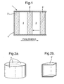
- Figure 1 shows a schematic longitudinal cross-sectional view of a cylindrical projectile 1 according to the invention.
- the projectile has spaced loading layers 2 of simulated bird slurry that alternate, in the firing direction of the projectile, with support elements 3.
- Each layer 2 provides a respective pulse of simulated bird slurry when the projectile is fired at a target.
- the support elements 3 help the simulated bird slurry layers 2 to maintain their shape and spacing.
- the projectile 1 has a surrounding sabot 4 that facilitates loading of the projectile into a gas gun. On firing, the sabot also traps propellant gases and allows the projectile to attain high velocities.
- the sabot is constructed so that the forward face of the endmost simulated bird slurry layer is exposed. The projectile is loaded into the barrel of the gun with this face closest to the muzzle.
- the sabot 4 is made up of several pieces of low density material, such as plastic, aluminium, or wood.
- the pieces of the sabot are loosely connected such that, when the projectile is fired and leaves the barrel of the gun, the increased air resistance outside the barrel causes the pieces to fall away as the projectile continues its flight towards the target.
- Each of the support elements 3 has a significantly lower density than that of each of the simulated bird slurry layers 2. Thus, on impact with the target, the support elements 3 cause little additional loading of the target.
- the simulated bird slurry impacts the target in discrete pulses.
- the pulse frequency is determined by the projectile velocity and the combined thickness of one simulated bird slurry layer and one support layer.
- the projectile velocity on impact is about 200 ms -1 .
- an impact pulse frequency of about 3 kHz can be achieved, which corresponds with the typical blade passing frequency of a low pressure rotor.
- Each simulated bird slurry layer 4 has a thickness of about 20 mm.
- the simulated bird slurry typically contains a gel mixed with polymer particles.
- the gelling agent used in the gel may be gelatine, or any one of a number of substances including agar, carrageenan, pectin, konnyaku, locust bean gum, alginates, gellan gum, hypromellose, hydroxypropyl methyl cellulose, xanthan gum, and starch.
- the gel is typically minced after forming for mixing with the polymer particles.
- the polymer particles may be polystyrene balls.
- the support elements 4 are formed from (typically expanded) polystyrene or other low density materials such as plastic, aluminium, or wood.
- each support element may consist of discrete sub-elements.
- the support element may be formed from particulate material, which is sufficiently compacted to maintain the support element's shape during acceleration in the barrel, but after exiting from the muzzle can break up under the influence of air resistance.
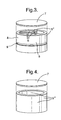
- Fig. 2a shows a disc-shaped support element that is divided into three equal sized 120° sub-elements or segments 5.
- the boundaries between the sub-elements extend between the faces of the support element that contact adjacent simulated bird slurry layers, and hence extend in the direction of travel of the projectile when it is fired.
- the sub-elements tend to move laterally outwards and fall away under the influence of air resistance.
- inventions of the invention may comprise support elements consisting of two or four, or other numbers of sub-elements, and the sub-elements may vary in size and shape.
- the support elements may have one or more cavities. In particular, they may be hollow or may contain pores in order to reduce their overall mass.
- sub-element 5' shown in Fig. 2b , may be brought together with two identical sub-elements to form a hollow, disc-shaped support element having the same external shape as the solid-form support element shown in Fig. 2a .
- Fig. 3 shows another disc-shaped support element formed from three equal sized 120° sub-elements or segments 5''.
- Each sub-element has wall portions which define a cavity in the form of a channel 6 extending in the axial direction of the projectile.
- Thin caps 7 at either end of the support element cover the channels and provide fore and aft wall portions which spread the load during acceleration and prevent the adjacent bird slurry layers entering the channels.
- Fig. 4 shows another disc-shaped support element.
- three equal sized sub-elements 5''' have wall portions which form a ring around a single central channel.
- the support element has end caps 7 (only one is shown) for supporting the adjacent bird slurry layers and spreading the load during acceleration.
- one or more grooves can be provided around that outer surface.
- the outer surface is exposed to still air.
- the grooves can then increase the aerodynamic drag on the surface, encouraging the sub-elements making up the support element also to fall away.
- the support element of Fig. 3 has an annular groove 9 extending around its perimeter surface 8.
- Such grooves need not be continuous, but to increase air resistance they preferably extend substantially perpendicularly to the direction of travel of the projectile.
- Test procedures using the projectile described above to simulate multiple ballistic impacts caused by bird slurry can be relatively inexpensive to perform and rapid to set-up. However, this is not necessarily at the expense of simulation accuracy. Indeed, compared to full engine or rotor test rig experiments, an advantage of testing using the projectile is that access to the vanes is improved. This allows, for example, more detailed measurements to be made using high-speed photography.
Landscapes
- Engineering & Computer Science (AREA)
- Chemical & Material Sciences (AREA)
- Combustion & Propulsion (AREA)
- Physics & Mathematics (AREA)
- General Physics & Mathematics (AREA)
- General Engineering & Computer Science (AREA)
- Thermal Sciences (AREA)
- Investigating Strength Of Materials By Application Of Mechanical Stress (AREA)
- Toys (AREA)
- Turbine Rotor Nozzle Sealing (AREA)
- Aiming, Guidance, Guns With A Light Source, Armor, Camouflage, And Targets (AREA)
Applications Claiming Priority (1)
| Application Number | Priority Date | Filing Date | Title |
|---|---|---|---|
| GBGB0810108.1A GB0810108D0 (en) | 2008-06-04 | 2008-06-04 | Projectile for simulating multiple ballistic impacts |
Publications (2)
| Publication Number | Publication Date |
|---|---|
| EP2131173A2 true EP2131173A2 (de) | 2009-12-09 |
| EP2131173A3 EP2131173A3 (de) | 2016-07-06 |
Family
ID=39638077
Family Applications (1)
| Application Number | Title | Priority Date | Filing Date |
|---|---|---|---|
| EP09251266.4A Withdrawn EP2131173A3 (de) | 2008-06-04 | 2009-05-07 | Geschoss zum Simulieren mehrerer Geschosseinschläge |
Country Status (3)
| Country | Link |
|---|---|
| EP (1) | EP2131173A3 (de) |
| CA (1) | CA2665880C (de) |
| GB (1) | GB0810108D0 (de) |
Cited By (5)
| Publication number | Priority date | Publication date | Assignee | Title |
|---|---|---|---|---|
| FR2997499A1 (fr) * | 2012-10-31 | 2014-05-02 | Snecma | Dispositif de test d'ingestion d'objets par une turbomachine |
| EP3032214A4 (de) * | 2013-08-05 | 2017-03-08 | IHI Corporation | Geschoss zum simulieren eines vogelschlags |
| EP2310797B1 (de) * | 2008-08-11 | 2018-04-18 | Deutsches Zentrum für Luft- und Raumfahrt e.V. | Projektil |
| CN111551458A (zh) * | 2020-03-25 | 2020-08-18 | 南京航空航天大学 | 一种模拟多叶片打靶的试验装置及方法 |
| CN117969001A (zh) * | 2024-01-31 | 2024-05-03 | 重庆大学 | 航空发动机零件旋转状态下鸟撞试验装置及试验方法 |
Families Citing this family (1)
| Publication number | Priority date | Publication date | Assignee | Title |
|---|---|---|---|---|
| CN109297664B (zh) * | 2018-11-01 | 2024-05-07 | 杭州应敏科技有限公司 | 全自动机械碰撞试验机 |
Family Cites Families (1)
| Publication number | Priority date | Publication date | Assignee | Title |
|---|---|---|---|---|
| DE2845431C1 (de) * | 1978-10-19 | 1991-10-24 | Rheinmetall Gmbh | Wuchtgeschoss |
-
2008
- 2008-06-04 GB GBGB0810108.1A patent/GB0810108D0/en not_active Ceased
-
2009
- 2009-05-07 EP EP09251266.4A patent/EP2131173A3/de not_active Withdrawn
- 2009-05-11 CA CA2665880A patent/CA2665880C/en not_active Expired - Fee Related
Non-Patent Citations (1)
| Title |
|---|
| None * |
Cited By (5)
| Publication number | Priority date | Publication date | Assignee | Title |
|---|---|---|---|---|
| EP2310797B1 (de) * | 2008-08-11 | 2018-04-18 | Deutsches Zentrum für Luft- und Raumfahrt e.V. | Projektil |
| FR2997499A1 (fr) * | 2012-10-31 | 2014-05-02 | Snecma | Dispositif de test d'ingestion d'objets par une turbomachine |
| EP3032214A4 (de) * | 2013-08-05 | 2017-03-08 | IHI Corporation | Geschoss zum simulieren eines vogelschlags |
| CN111551458A (zh) * | 2020-03-25 | 2020-08-18 | 南京航空航天大学 | 一种模拟多叶片打靶的试验装置及方法 |
| CN117969001A (zh) * | 2024-01-31 | 2024-05-03 | 重庆大学 | 航空发动机零件旋转状态下鸟撞试验装置及试验方法 |
Also Published As
| Publication number | Publication date |
|---|---|
| EP2131173A3 (de) | 2016-07-06 |
| GB0810108D0 (en) | 2008-07-09 |
| CA2665880A1 (en) | 2009-12-04 |
| CA2665880C (en) | 2014-02-11 |
Similar Documents
| Publication | Publication Date | Title |
|---|---|---|
| US8047136B2 (en) | Projectile for simulating multiple ballistic impacts | |
| CA2665880C (en) | Projectile for simulating multiple ballistic impacts | |
| US8220396B2 (en) | Projectile | |
| US11614311B1 (en) | Prefragmented warheads with enhanced performance | |
| Charron | Estimation of velocity distribution of fragmenting warheads using a modified Gurney method | |
| CN109388914B (zh) | 一种基于预制条形孔圆筒装置的炸药内爆炸威力评价方法 | |
| JP2010090890A (ja) | バードストライクの出来事を模擬実験するための人工鳥型発射物 | |
| Wei et al. | Comparative study on damage effects of penetration and explosion modes on airport runway | |
| KR102626958B1 (ko) | 추진장약 | |
| US12072171B1 (en) | Prefragmented warheads with enhanced performance | |
| Held | Impulse method for the blast contour of cylindrical high explosive charges | |
| RU2395059C1 (ru) | Способ стендового испытания катапультного устройства ракеты при вертикальном запуске | |
| RU2288420C2 (ru) | Способ стендового испытания поршневого катапультного устройства ракеты | |
| Waggener | The evolution of air target warheads | |
| RU2180093C1 (ru) | Сверхзвуковой реактивный снаряд | |
| US3010399A (en) | Impulse generator | |
| RU2679830C1 (ru) | Осколочно-фугасный боеприпас | |
| RU2248515C1 (ru) | Вращающаяся ракета | |
| CN114251984A (zh) | 一种固体推进装置的等效靶标设计方法 | |
| RU2789247C1 (ru) | Взрывная камера ударной трубы взрывного действия | |
| RU215635U1 (ru) | Конструкция сотовой кассеты для пуска неуправляемых реактивных авиационных снарядов с ударных вертолетов | |
| Wang et al. | Design and experimental studies on ceramic port cover for dual pulse motor | |
| RU2082936C1 (ru) | Способ имитации условий старта ракеты из подводной лодки и система для его осуществления | |
| RU2837546C1 (ru) | Боеприпас | |
| Xiao et al. | Influence of venting parameters on erosive burning of partially cut multi-perforated stick propellants |
Legal Events
| Date | Code | Title | Description |
|---|---|---|---|
| PUAI | Public reference made under article 153(3) epc to a published international application that has entered the european phase |
Free format text: ORIGINAL CODE: 0009012 |
|
| AK | Designated contracting states |
Kind code of ref document: A2 Designated state(s): AT BE BG CH CY CZ DE DK EE ES FI FR GB GR HR HU IE IS IT LI LT LU LV MC MK MT NL NO PL PT RO SE SI SK TR |
|
| RAP1 | Party data changed (applicant data changed or rights of an application transferred) |
Owner name: ROLLS-ROYCE PLC |
|
| PUAL | Search report despatched |
Free format text: ORIGINAL CODE: 0009013 |
|
| AK | Designated contracting states |
Kind code of ref document: A3 Designated state(s): AT BE BG CH CY CZ DE DK EE ES FI FR GB GR HR HU IE IS IT LI LT LU LV MC MK MT NL NO PL PT RO SE SI SK TR |
|
| AX | Request for extension of the european patent |
Extension state: AL BA RS |
|
| RIC1 | Information provided on ipc code assigned before grant |
Ipc: G01M 7/08 20060101AFI20160530BHEP Ipc: G01M 15/14 20060101ALI20160530BHEP |
|
| STAA | Information on the status of an ep patent application or granted ep patent |
Free format text: STATUS: REQUEST FOR EXAMINATION WAS MADE |
|
| 17P | Request for examination filed |
Effective date: 20161221 |
|
| RIC1 | Information provided on ipc code assigned before grant |
Ipc: G01M 15/14 20060101ALI20170207BHEP Ipc: G01M 7/08 20060101AFI20170207BHEP |
|
| GRAP | Despatch of communication of intention to grant a patent |
Free format text: ORIGINAL CODE: EPIDOSNIGR1 |
|
| STAA | Information on the status of an ep patent application or granted ep patent |
Free format text: STATUS: GRANT OF PATENT IS INTENDED |
|
| INTG | Intention to grant announced |
Effective date: 20170411 |
|
| STAA | Information on the status of an ep patent application or granted ep patent |
Free format text: STATUS: THE APPLICATION IS DEEMED TO BE WITHDRAWN |
|
| 18D | Application deemed to be withdrawn |
Effective date: 20170822 |