EP2131125B1 - Door storage compartment for a cooling device - Google Patents
Door storage compartment for a cooling device Download PDFInfo
- Publication number
- EP2131125B1 EP2131125B1 EP09100306.1A EP09100306A EP2131125B1 EP 2131125 B1 EP2131125 B1 EP 2131125B1 EP 09100306 A EP09100306 A EP 09100306A EP 2131125 B1 EP2131125 B1 EP 2131125B1
- Authority
- EP
- European Patent Office
- Prior art keywords
- storage compartment
- flap
- door storage
- compartment according
- pivot axis
- Prior art date
- Legal status (The legal status is an assumption and is not a legal conclusion. Google has not performed a legal analysis and makes no representation as to the accuracy of the status listed.)
- Active
Links
Images
Classifications
-
- F—MECHANICAL ENGINEERING; LIGHTING; HEATING; WEAPONS; BLASTING
- F25—REFRIGERATION OR COOLING; COMBINED HEATING AND REFRIGERATION SYSTEMS; HEAT PUMP SYSTEMS; MANUFACTURE OR STORAGE OF ICE; LIQUEFACTION SOLIDIFICATION OF GASES
- F25D—REFRIGERATORS; COLD ROOMS; ICE-BOXES; COOLING OR FREEZING APPARATUS NOT OTHERWISE PROVIDED FOR
- F25D23/00—General constructional features
- F25D23/02—Doors; Covers
- F25D23/025—Secondary closures
-
- F—MECHANICAL ENGINEERING; LIGHTING; HEATING; WEAPONS; BLASTING
- F25—REFRIGERATION OR COOLING; COMBINED HEATING AND REFRIGERATION SYSTEMS; HEAT PUMP SYSTEMS; MANUFACTURE OR STORAGE OF ICE; LIQUEFACTION SOLIDIFICATION OF GASES
- F25D—REFRIGERATORS; COLD ROOMS; ICE-BOXES; COOLING OR FREEZING APPARATUS NOT OTHERWISE PROVIDED FOR
- F25D23/00—General constructional features
- F25D23/02—Doors; Covers
- F25D23/04—Doors; Covers with special compartments, e.g. butter conditioners
-
- F—MECHANICAL ENGINEERING; LIGHTING; HEATING; WEAPONS; BLASTING
- F25—REFRIGERATION OR COOLING; COMBINED HEATING AND REFRIGERATION SYSTEMS; HEAT PUMP SYSTEMS; MANUFACTURE OR STORAGE OF ICE; LIQUEFACTION SOLIDIFICATION OF GASES
- F25D—REFRIGERATORS; COLD ROOMS; ICE-BOXES; COOLING OR FREEZING APPARATUS NOT OTHERWISE PROVIDED FOR
- F25D23/00—General constructional features
- F25D23/02—Doors; Covers
- F25D23/021—Sliding doors
Definitions
- the present invention relates to a door storage compartment, in particular a butter compartment, for a refrigeration appliance, in particular a household refrigerating appliance, i. a container which is separable from the rest of the interior of the refrigerator to store refrigerated goods at another, usually slightly higher temperature than the rest of the interior can.
- a butter compartment is normally mounted on the inside of a door of the refrigerator near its upper edge.
- the butter compartment is closed by a flap that pivots upward to open about a horizontal axis. If one would close the door with the flap swung open in such a refrigeration device, the flap would abut against the body of the refrigeration device and break off. To avoid this, the flap usually does not have a stable raised position, but falls immediately when released. A user who wants to access the contents of the butter compartment therefore always needs a hand to hold the flap open.
- KR 2004 0069726 A shows a door storage compartment according to the preamble of claim 1, and discloses a door storage compartment for a refrigeration device having a container and a flap, which from a closed position on a front side of the container initially pivotable about a horizontal axis and then slidable into an open position above the top of the container is.
- the object of the present invention is to provide a door storage compartment which is convenient and safe to handle.
- the object is achieved by a door storage compartment with the features of claim 1.
- the displaceability of the axis allows the flap to deflect in the depth direction, so that even if in an attempt to close the refrigerator door with the door open, the flap protrudes and against the body of the refrigerator, the flap may escape damage by dodging in the depth direction. Pivoting the flap around the two axes simultaneously implies a simultaneous one Movement of at least one of the pivot axes, so that the retreat of the flap can take place simultaneously with the opening.
- a guide for the first pivot axis is preferably provided on a side wall of the box. It may in particular be designed as a guide groove.
- the first pivot axis is preferably formed by arranged on the side edges of the flap pin.
- the guide groove preferably runs below a bottom plate of the box or above a ceiling plate of the same, so that stored in the box or on the bottom plate refrigerated goods does not hinder the retraction of the flap.
- the guide groove extends in a space between two floor panels or two ceiling panels of the box, so that also refrigerated high altitude, which is stored below the door storage compartment, for example in a door rack, or an obstacle above the door storage compartment, the back of the Flap can not block.
- the flap is guided in the guide grooves or the link between the pivoting and the retreat of the flap is such that the flap overlaps in the open position predominantly with a horizontal plate of the door storage compartment, ie one of the floor panels or one of the ceiling panels of the door storage compartment.
- a guide groove leading the first pivot axis and a guide groove leading the second pivot axis diverge vertically toward the front.
- the two guide grooves are preferably arranged vertically one above the other. They should not touch or cross each other as much as possible.
- first guide groove and, if present, also the second guide groove rises slightly over a predominant part of its length to the front side.
- the flap moves slightly downwards as it recedes to the open position, and it is sufficient to overcome an initial resistance to allow the flap to fully open. The sticking of the flap in a partially open position, in which a collision with the body would be possible, is thus avoided.
- the guide grooves are guided so that when the first pivot axis is located at the locally lowest point of the lower guide groove, the second pivot axis is spaced from a highest point of the upper guide groove. This gives the flap as a whole the opportunity, at the beginning of the swinging-up, when the first pivot axis leaves the locally lowest point, to move upwards.
- a resistance must first be overcome, and the flap is stable in the closed position.
- An angled web at an edge of the flap remote from the first pivot axis facilitates gripping and pulling forward of the flap when in the open position.
- the closed position of the flap is preferably defined by abutting a remote from the first pivot axis edge of the flap on a horizontal plate of the box.
- an engagement opening is preferably formed, which facilitates the gripping and opening of the flap, without a risk of demolition projecting handling section must be present on the flap.
- the door storage compartment is preferably designed as a butter compartment.
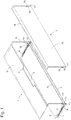
- Fig. 1 Butter compartment shown comprises a substantially cuboid box 1, which is intended to be mounted on the inside of a refrigerator door, and provided for pivotally mounting on the box 1 flap 2.
- fasteners such as locking recesses or projections on side walls 3 of the box for hanging on vertical Holmen the refrigerator door are known in the art and for clarity in Fig. 1 not shown.
- a vertical rear wall 4 Between the side walls 3 extend a vertical rear wall 4, a ceiling plate 5, and an upper and a lower bottom plate 6, 7.
- Front edges of the bottom plates 6, 7 extend to near leading edges of the side walls 3; a front edge of the ceiling plate 5 is slightly more set back than the front edges of the bottom plates 6, 7 and centrally provided with an engagement recess 8.
- an upper rail 9 and a lower rail 10 are each recessed. Both rails extend over a large part of their length in a gap 11 delimited by the bottom plates 6, 7, rising slightly towards the open front side of the box 1. Towards the front, the upper rail 9 terminates with an approximately quarter-circular upwardly curved portion 12. A downwardly curved portion 13 at the front end of the lower rail 10 has a substantially smaller radius of curvature than the portion 12th
- the flap 2 has essentially the shape of an inverted L-profile with a front panel 15 covering the front of the box 1 and an angled from the upper edge of the front panel 15 web 16. From a lower edge of the front panel 15 are pins 17 in the opposite direction from. Another pair of pins 18 is formed on from the front plate 15 rearwardly projecting tabs 19.
- the pins 17 are provided to engage the lower rail 10 and to define a first pivot axis of the cap 2; the pins 18 form a second pivot axis by engaging in the upper rails 9.
- the front panel 15 covers the open front of the box 1, and the web 16 abuts both sides of the engagement recess 8 at the front edge of the ceiling plate 5 at.
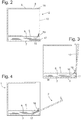
- This condition is in Fig. 2 shown in section.
- the pins 17 are at a locally lowest point at the front end of the lower rails 10, while the Pins 18 from the front upper end of the rails 9 are a piece away.
- the flap 2 is stably held in its closed position.
- a (not shown) elastic buffer may be mounted in the gap 11 on the rear wall 4 to a hard, noisy striking the flap 2 in the position of Fig. 5 to avoid.
- a gap 20 is open, which makes it easier for the user to grab the flap 2 on the web 16, to pull out of the gap 11 and in the closed position of Fig. 2 to swing back.
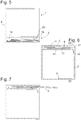
- FIG. 6 and 7 show a second embodiment of the butter compartment according to the invention.
- a gap 11 in which the flap 2 recedes in the open position, not formed on the ground, but between an upper and a lower ceiling plate 5, 22 of the box 1, and pairs of pins 17, 18, the two pivot axes of the flap. 2 are defined, are arranged at the upper edge or adjacent thereto.
- the movement of the flap 2 between the open and closed positions is substantially mirror-inverted with respect to FIG Fig. 2 to 5 described. Since in this embodiment, the weight of the flap 2 is only partially effective to propel a movement of the flap in the open position, the flap can also in an unstable, partially open equilibrium position, as in Fig. 7 shown, remain. Damage to the flap when closing the door is still not to be feared, since the flap 2, when it bumps against the body of the refrigerator, recedes into the gap 11 inside.
- Engagement recesses 23, 24 are formed in this embodiment in the bottom plate 6 and in the upper ceiling plate 5, so that in the open position the edge of the flap 2 can be easily gripped between two fingers and pivoted up or pulled out of the gap 11.
Description
Die vorliegende Erfindung betrifft ein Türablagefach, insbesondere ein Butterfach, für ein Kältegerät, insbesondere ein Haushalts-Kältegerät, d.h. einen Behälter, der vom restlichen Innenraum des Kühlschranks abtrennbar ist, um darin Kühlgut auf einer anderen, meist etwas höheren Temperatur als im restlichen Innenraum lagern zu können. Ein solches Butterfach ist normalerweise an der Innenseite einer Tür des Kühlschranks nahe ihrem oberen Rand montiert.The present invention relates to a door storage compartment, in particular a butter compartment, for a refrigeration appliance, in particular a household refrigerating appliance, i. a container which is separable from the rest of the interior of the refrigerator to store refrigerated goods at another, usually slightly higher temperature than the rest of the interior can. Such a butter compartment is normally mounted on the inside of a door of the refrigerator near its upper edge.
Bei den meisten derzeit auf dem Markt befindlichen Kühlschränken ist das Butterfach durch eine Klappe abgeschlossen, die zum Öffnen um eine horizontale Achse aufwärts schwenkbar ist. Würde man bei einem solchen Kältegerät die Tür bei aufgeschwenkter Klappe schließen, so würde die Klappe gegen den Korpus des Kältegeräts anstoßen und abbrechen. Um dies zu vermeiden, hat die Klappe in der Regel keine stabile angehobene Stellung, sondern fällt sofort wieder zu, wenn sie losgelassen wird. Ein Benutzer, der auf den Inhalt des Butterfachs zugreifen möchte, braucht daher immer eine Hand, um die Klappe offen zu halten.For most refrigerators currently on the market, the butter compartment is closed by a flap that pivots upward to open about a horizontal axis. If one would close the door with the flap swung open in such a refrigeration device, the flap would abut against the body of the refrigeration device and break off. To avoid this, the flap usually does not have a stable raised position, but falls immediately when released. A user who wants to access the contents of the butter compartment therefore always needs a hand to hold the flap open.
Aufgabe der vorliegenden Erfindung ist, ein Türablagefach anzugeben, das bequem und sicher zu handhaben ist.The object of the present invention is to provide a door storage compartment which is convenient and safe to handle.
Die Aufgabe wird gelöst durch ein Türablagefach mit den Merkmalen des Anspruchs 1. Die Verschiebbarkeit der Achse ermöglicht ein Ausweichen der Klappe in Tiefenrichtung, so dass, selbst wenn bei dem Versuch, die Kühlschranktür bei offener Klappe zu schließen, die Klappe übersteht und gegen den Korpus des Kühlschranks stößt, die Klappe einer Beschädigung durch Ausweichen in Tiefenrichtung entgehen kann. Ein Schwenken der Klappe um die zwei Achsen gleichzeitig impliziert eine gleichzeitige Bewegung wenigstens einer der Schwenkachsen, so dass das Zurückweichen der Klappe bereits gleichzeitig mit dem Öffnen stattfinden kann.The object is achieved by a door storage compartment with the features of
Eine Führung für die erste Schwenkachse ist vorzugsweise an einer Seitenwand des Kastens vorgesehen. Sie kann insbesondere als eine Führungsnut ausgebildet sein.A guide for the first pivot axis is preferably provided on a side wall of the box. It may in particular be designed as a guide groove.
Die erste Schwenkachse ist vorzugsweise durch an den Seitenrändern der Klappe angeordnete Zapfen gebildet.The first pivot axis is preferably formed by arranged on the side edges of the flap pin.
Die Führungsnut verläuft vorzugsweise unterhalb einer Bodenplatte des Kastens oder oberhalb einer Deckenplatte desselben, so dass in dem Kasten bzw. auf dessen Bodenplatte aufbewahrtes Kühlgut das Zurückweichen der Klappe nicht behindert.The guide groove preferably runs below a bottom plate of the box or above a ceiling plate of the same, so that stored in the box or on the bottom plate refrigerated goods does not hinder the retraction of the flap.
Besonders bevorzugt ist, dass die Führungsnut in einem Zwischenraum zwischen zwei Bodenplatten oder zwei Deckenplatten des Kastens verläuft, so dass auch Kühlgut großer Höhe, das unterhalb des Türablagefachs, zum Beispiel in einem Türabsteller, aufbewahrt ist, oder ein Hindernis oberhalb des Türablagefachs das Zurückweichen der Klappe nicht blockieren kann.It is particularly preferred that the guide groove extends in a space between two floor panels or two ceiling panels of the box, so that also refrigerated high altitude, which is stored below the door storage compartment, for example in a door rack, or an obstacle above the door storage compartment, the back of the Flap can not block.
Vorzugsweise ist die Klappe in den Führungsnuten so geführt bzw. die Verknüpfung zwischen dem Schwenken und dem Zurückweichen der Klappe ist derart, dass die Klappe in offener Stellung überwiegend mit einer horizontalen Platte des Türablagefachs, d.h. einer der Bodenplatten oder einer der Deckenplatten des Türablagefachs überlappt.Preferably, the flap is guided in the guide grooves or the link between the pivoting and the retreat of the flap is such that the flap overlaps in the open position predominantly with a horizontal plate of the door storage compartment, ie one of the floor panels or one of the ceiling panels of the door storage compartment.
Um die Klappe zwischen einer im Wesentlichen vertikalen, die Vorderseite des Kastens verschließenden Stellung und einer im Wesentlichen horizontalen offenen Stellung geeignet zu führen, ist bevorzugt, dass eine die erste Schwenkachse führende Führungsnut und eine die zweite Schwenkachse führende Führungsnut zu der Vorderseite hin vertikal divergieren.To properly guide the flap between a substantially vertical position closing the front of the box and a substantially horizontal open position, it is preferred that a guide groove leading the first pivot axis and a guide groove leading the second pivot axis diverge vertically toward the front.
Die zwei Führungsnuten sind vorzugsweise vertikal übereinander angeordnet. Sie sollten einander möglichst weder berühren noch kreuzen.The two guide grooves are preferably arranged vertically one above the other. They should not touch or cross each other as much as possible.
Um die Klappe in der geschlossenen Stellung zu stabilisieren, ist es hilfreich, wenn eine untere der die Schwenkachsen führenden Führungsnuten an ihrem der Vorderseite benachbarten Ende einen lokal tiefsten Punkt aufweist.To stabilize the flap in the closed position, it is helpful if a lower of the guide axes leading the pivot axes has a locally lowest point at its end adjacent to the front side.
Zweckmäßig ist auch, wenn die erste Führungsnut und, wenn vorhanden, auch die zweite Führungsnut auf einem überwiegenden Teil ihrer Länge zu der Vorderseite hin leicht ansteigt. So bewegt sich die Klappe gleichzeitig leicht abwärts, wenn sie in die offene Stellung zurückweicht, und es genügt die Überwindung eines Anfangswiderstandes, damit die Klappe vollständig aufgeht. Das Steckenbleiben der Klappe in einer teiloffenen Stellung, in der eine Kollision mit dem Korpus möglich wäre, wird so vermieden.It is also expedient if the first guide groove and, if present, also the second guide groove rises slightly over a predominant part of its length to the front side. Thus, at the same time, the flap moves slightly downwards as it recedes to the open position, and it is sufficient to overcome an initial resistance to allow the flap to fully open. The sticking of the flap in a partially open position, in which a collision with the body would be possible, is thus avoided.
Besonders vorteilhaft ist, wenn die Führungsnuten so geführt sind, dass wenn die erste Schwenkachse sich an dem lokal tiefsten Punkt der unteren Führungsnut befindet, die zweite Schwenkachse von einem höchsten Punkt der oberen Führungsnut beabstandet ist. Dies gibt der Klappe als Ganzes die Möglichkeit, zu Beginn des Aufschwenkens, wenn die erste Schwenkachse den lokal tiefsten Punkt verlässt, nach oben auszuweichen. So muss, um die Klappe aufzuschwenken, zunächst ein Widerstand überwunden werden, und die Klappe ist in der geschlossenen Stellung stabil.It is particularly advantageous if the guide grooves are guided so that when the first pivot axis is located at the locally lowest point of the lower guide groove, the second pivot axis is spaced from a highest point of the upper guide groove. This gives the flap as a whole the opportunity, at the beginning of the swinging-up, when the first pivot axis leaves the locally lowest point, to move upwards. Thus, in order to open the flap, a resistance must first be overcome, and the flap is stable in the closed position.
Ein abgewinkelter Steg an einem von der ersten Schwenkachse abgewandten Rand der Klappe erleichtert das Greifen und Vorziehen der Klappe, wenn sie sich in der offenen Stellung befindet.An angled web at an edge of the flap remote from the first pivot axis facilitates gripping and pulling forward of the flap when in the open position.
Die geschlossene Stellung der Klappe ist vorzugsweise durch ein Anschlagen eines von der ersten Schwenkachse abgewandten Randes der Klappe an einer horizontalen Platte des Kastens definiert.The closed position of the flap is preferably defined by abutting a remote from the first pivot axis edge of the flap on a horizontal plate of the box.
Zwischen dem Rand der Klappe und der Platte ist vorzugsweise eine Eingrifföffnung gebildet, die das Greifen und Öffnen der Klappe erleichtert, ohne dass ein abbruchgefährdeter vorspringender Handhabungsabschnitt an der Klappe vorhanden sein muss.Between the edge of the flap and the plate, an engagement opening is preferably formed, which facilitates the gripping and opening of the flap, without a risk of demolition projecting handling section must be present on the flap.
Das Türablagefach ist vorzugsweise als Butterfach ausgebildet.The door storage compartment is preferably designed as a butter compartment.
Weitere Merkmale und Vorteile der Erfindung ergeben sich aus der nachfolgenden Beschreibung von Ausführungsbeispielen unter Bezugnahme auf die beigefügten Figuren. Es zeigen:
- Fig. 1
- eine perspektivische auseinander gezogene Ansicht eines Kastens und einer Klappe eines erfindungsgemäßen Butterfachs;
- Fig. 2
- einen Schnitt durch das Butterfach mit der Klappe in geschlossener Stellung;
- Fig. 3
- einen Schnitt durch das Butterfach mit teilgeöffneter Klappe;
- Fig. 4
- einen zweiten Schnitt durch das Butterfach mit teilgeöffneter Klappe;
- Fig. 5
- einen Schnitt durch das Butterfach mit vollständig geöffneter Klappe;
- Fig. 6
- einen Schnitt durch ein Butterfach gemäß einer zweiten Ausgestaltung der Erfindung mit geschlossener Klappe;
- Fig. 7
- einen Schnitt durch das Butterfach der
Fig. 6 in teilgeöffneter Stellung.
- Fig. 1
- a perspective exploded view of a box and a flap of a butter compartment according to the invention;
- Fig. 2
- a section through the butter compartment with the flap in the closed position;
- Fig. 3
- a section through the butter compartment with partially open flap;
- Fig. 4
- a second cut through the butter compartment with partially opened flap;
- Fig. 5
- a section through the butter compartment with fully opened flap;
- Fig. 6
- a section through a butter compartment according to a second embodiment of the invention with the flap closed;
- Fig. 7
- a section through the butter compartment of the
Fig. 6 in partially open position.
Das in
Die Klappe 2 hat im Wesentlichen die Form eines invertierten L-Profils mit einer die Vorderseite des Kastens 1 überdeckenden Frontplatte 15 und einem vom oberen Rand der Frontplatte 15 nach hinten abgewinkelten Steg 16. Von einem unteren Rand der Frontplatte 15 stehen Zapfen 17 in entgegengesetzte Richtung ab. Ein weiteres Paar von Zapfen 18 ist an von der Frontplatte 15 nach hinten abstehenden Laschen 19 gebildet. Die Zapfen 17 sind vorgesehen, um in die untere Schiene 10 einzugreifen und eine erste Schwenkachse der Kappe 2 zu definieren; die Zapfen 18 bilden eine zweite Schwenkachse, indem sie in die oberen Schienen 9 eingreifen.The
Wenn die Klappe 2 in der in
Wenn ein Benutzer in die Eingriffaussparung 8 eingreift und die Klappe 2 nach vorn (bzw. nach rechts in den
Ein (nicht dargestellter) elastischer Puffer kann im Spalt 11 an der Rückwand 4 angebracht sein, um ein hartes, geräuschvolles Anschlagen der Klappe 2 in der Stellung der
Zwischen dem vorderen Rand der oberen Bodenplatte 6 und dem Steg 16 der Klappe 2 ist ein Spalt 20 offen, der es dem Benutzer erleichtert, die Klappe 2 am Steg 16 zu greifen, aus dem Spalt 11 heraus zu ziehen und in die geschlossene Stellung der
Eingriffaussparungen 23, 24 sind bei dieser Ausgestaltung in der Bodenplatte 6 bzw. in der oberen Deckenplatte 5 gebildet, so dass in offener Stellung der Rand der Klappe 2 leicht zwischen zwei Fingern gegriffen und hoch geschwenkt bzw. aus dem Spalt 11 herausgezogen werden kann.Engagement recesses 23, 24 are formed in this embodiment in the
Claims (18)
- Door storage compartment for a refrigeration appliance, in particular a domestic refrigeration appliance, having a box (1) and a flap (2) which can be positioned in front of an open front side of the box (1), wherein a first pivot axis (17; 18) of the flap (2) can be moved on the box (1) in a guided manner in the depth direction, characterised in that the flap (2) has a second pivot axis (18; 17) which can moved on the box in a guide groove (9; 10).
- Door storage compartment according to claim 1, characterised in that a guide (9; 10) for the guided movement of the first pivot axis (17; 18) is provided on a side wall (3) of the box (1).
- Door storage compartment according to one of the preceding claims, characterised in that the first pivot axis (17; 18) is formed by pins (17; 18) arranged on the side edges of the flap (2).
- Door storage compartment according to one of the preceding claims, characterised in that the second pivot axis (18; 17) is formed by pins (18; 17) arranged on the side edges of the flap (2).
- Door storage compartment according to one of the preceding claims, characterised in that for the guided movement of the flap (2) the pins (17; 18) are guided in a moveable and rotatable manner into the guide grooves (9; 10).
- Door storage compartment according to one of the preceding claims, characterised in that the flap (2) can be moved into a closed position in front of the front side and into an open position at least with the aid of the first pivot axis (17; 18) which can be moved in a guided manner.
- Door storage compartment according to one of the preceding claims, characterised in that the guide groove (9; 10) runs below a baseplate (6) or above a ceiling plate (22) of the box (1).
- Door storage compartment according to one of the preceding claims, characterised in that the guide groove (9, 10) runs in an intermediate space (11) between two base plates (6; 7) or between two ceiling plates (5, 22) of the box.
- Door storage compartment according to one of the preceding claims, characterised in that in an open position the flap (2) at least largely overlaps with at least one adjacent horizontal plate (5; 6; 7; 22) of a butter compartment in the horizontal position.
- Door storage compartment according to one of the preceding claims, characterised in that a guide groove (9; 10) guiding the first pivot axis (17; 18) and a guide groove (10; 9) guiding the second pivot axis (18; 17) diverge vertically toward the front side.
- Door storage compartment according to one of the preceding claims, characterised in that the guide grooves (9; 10) guiding the pivot axes (17; 18) are arranged vertically one above the other.
- Door storage compartment according to claim 11, characterised in that a lower of the guide grooves (10) guiding the pivot axes (17; 18) has a locally deepest point at its end (13) adjacent to the front side.
- Door storage compartment according to claim 12, characterised in that when the first pivot axis (17) is located at the locally deepest point, the second pivot axis (18) is at a distance from a highest point of the upper guide groove (9).
- Door storage compartment according to one of the preceding claims, characterised in that over a large part of its length, at least the upper guide groove (9) rises toward the front side of the box (1).
- Door storage compartment according to one of the preceding claims, characterised in that the flap (2) has an angled web (16) on an edge facing away from the first pivot axis (17).
- Door storage compartment according to one of the preceding claims, characterised in that an edge of the flap (2) facing away from the first pivot axis (17) abuts a horizontal plate (5; 6) of the box (1) in the closed position.
- Door storage compartment according to claim 16, characterised in that the edge of the flap (2) and the plate (5; 6) delimit an engagement opening (8; 23).
- Door storage compartment according to one of the preceding claims, characterised in that it is embodied as a butter compartment.
Priority Applications (1)
| Application Number | Priority Date | Filing Date | Title |
|---|---|---|---|
| PL09100306T PL2131125T3 (en) | 2008-06-02 | 2009-05-29 | Door storage compartment for a cooling device |
Applications Claiming Priority (1)
| Application Number | Priority Date | Filing Date | Title |
|---|---|---|---|
| DE102008026381A DE102008026381A1 (en) | 2008-06-02 | 2008-06-02 | Door storage compartment for a refrigeration device |
Publications (3)
| Publication Number | Publication Date |
|---|---|
| EP2131125A2 EP2131125A2 (en) | 2009-12-09 |
| EP2131125A3 EP2131125A3 (en) | 2013-01-23 |
| EP2131125B1 true EP2131125B1 (en) | 2018-07-18 |
Family
ID=41090298
Family Applications (1)
| Application Number | Title | Priority Date | Filing Date |
|---|---|---|---|
| EP09100306.1A Active EP2131125B1 (en) | 2008-06-02 | 2009-05-29 | Door storage compartment for a cooling device |
Country Status (3)
| Country | Link |
|---|---|
| EP (1) | EP2131125B1 (en) |
| DE (1) | DE102008026381A1 (en) |
| PL (1) | PL2131125T3 (en) |
Cited By (1)
| Publication number | Priority date | Publication date | Assignee | Title |
|---|---|---|---|---|
| WO2021161056A1 (en) | 2020-02-14 | 2021-08-19 | Steelcase Inc. | Item of furniture, in particular a cabinet |
Families Citing this family (5)
| Publication number | Priority date | Publication date | Assignee | Title |
|---|---|---|---|---|
| DE102009029138B4 (en) | 2009-09-02 | 2016-10-27 | BSH Hausgeräte GmbH | Storage compartment for a refrigeration device |
| DE102010003877A1 (en) | 2010-04-12 | 2011-10-13 | BSH Bosch und Siemens Hausgeräte GmbH | Storage container with decorative trim |
| IT1403467B1 (en) * | 2010-12-16 | 2013-10-17 | Whirlpool Co | REFRIGERABLE COMPARTMENT FOR REFRIGERATOR |
| DE102011075561A1 (en) | 2011-05-10 | 2012-11-15 | BSH Bosch und Siemens Hausgeräte GmbH | Storage shelf e.g. butter shelf, for household refrigerator, has flap pivotable around joint axis, where distance of joint axis from front side and from lower side of box corresponds to quarter of distance of upper and lower edges of box |
| US10458696B1 (en) * | 2018-04-04 | 2019-10-29 | Whirlpool Corporation | Opening system for a storage bin assembly |
Family Cites Families (2)
| Publication number | Priority date | Publication date | Assignee | Title |
|---|---|---|---|---|
| KR100506598B1 (en) * | 2003-01-30 | 2005-08-08 | 삼성전자주식회사 | Container for refrigerator |
| DE10358734A1 (en) * | 2003-12-15 | 2005-07-14 | BSH Bosch und Siemens Hausgeräte GmbH | Refrigerating appliance with a container that can be closed with sliding doors |
-
2008
- 2008-06-02 DE DE102008026381A patent/DE102008026381A1/en not_active Withdrawn
-
2009
- 2009-05-29 EP EP09100306.1A patent/EP2131125B1/en active Active
- 2009-05-29 PL PL09100306T patent/PL2131125T3/en unknown
Non-Patent Citations (1)
| Title |
|---|
| None * |
Cited By (1)
| Publication number | Priority date | Publication date | Assignee | Title |
|---|---|---|---|---|
| WO2021161056A1 (en) | 2020-02-14 | 2021-08-19 | Steelcase Inc. | Item of furniture, in particular a cabinet |
Also Published As
| Publication number | Publication date |
|---|---|
| EP2131125A3 (en) | 2013-01-23 |
| DE102008026381A1 (en) | 2009-12-03 |
| EP2131125A2 (en) | 2009-12-09 |
| PL2131125T3 (en) | 2019-01-31 |
Similar Documents
| Publication | Publication Date | Title |
|---|---|---|
| EP2131125B1 (en) | Door storage compartment for a cooling device | |
| EP1819255B1 (en) | Refrigerator | |
| EP2473805B1 (en) | Refrigeration device with an extractable drawer | |
| EP2422150B1 (en) | Refrigeration appliance comprising a drawer | |
| WO2008135270A1 (en) | Fitting for a corner cupboard comprising a pull-out single-part shelf | |
| WO2017041902A1 (en) | Dispensing device | |
| WO2011009781A2 (en) | Refrigeration device having a removable lower shelf | |
| WO2011051131A2 (en) | Refrigeration device and corresponding ice maker | |
| EP2218992A2 (en) | Cooling device | |
| EP2691714B2 (en) | Refrigerator with an internal flap | |
| EP2299217B1 (en) | Storage compartment for a cooling device | |
| WO2019166205A1 (en) | Piece of furniture or domestic appliance and method for mounting a functional unit of a drawer element in a piece of furniture or domestic appliance | |
| EP2494282A2 (en) | Refrigeration device comprising an ice maker | |
| EP2344819B3 (en) | Refrigerator, in particular a household refrigerator | |
| DE3613439C2 (en) | Cooling device, especially a two-temperature refrigerator | |
| WO2010060783A2 (en) | Refrigeration device | |
| EP3032201A1 (en) | Refrigeration and/or freezer device | |
| EP2059744A1 (en) | Refrigerator comprising a receptacle that can be closed by means of sliding doors | |
| EP1660826B1 (en) | Refrigerating appliance | |
| DE102015203835B4 (en) | Household refrigeration appliance with a specific pull-out trolley | |
| DE102015222737A1 (en) | Refrigeration device with a crossbeam | |
| WO2011051126A2 (en) | Assembly for a refrigeration device | |
| DE102016011212A1 (en) | Fridge and / or freezer | |
| DE102008029032A1 (en) | Cooling device e.g. refrigerator for e.g. fruit, has cool products tray adjustably mounted in inner container, and stopper attached to laminar carrying element and arranged over cool products tray | |
| DE4207224C2 (en) | Cupboard compartment with a door closing the inside of the cupboard |
Legal Events
| Date | Code | Title | Description |
|---|---|---|---|
| PUAI | Public reference made under article 153(3) epc to a published international application that has entered the european phase |
Free format text: ORIGINAL CODE: 0009012 |
|
| AK | Designated contracting states |
Kind code of ref document: A2 Designated state(s): AT BE BG CH CY CZ DE DK EE ES FI FR GB GR HR HU IE IS IT LI LT LU LV MC MK MT NL NO PL PT RO SE SI SK TR |
|
| PUAL | Search report despatched |
Free format text: ORIGINAL CODE: 0009013 |
|
| AK | Designated contracting states |
Kind code of ref document: A3 Designated state(s): AT BE BG CH CY CZ DE DK EE ES FI FR GB GR HR HU IE IS IT LI LT LU LV MC MK MT NL NO PL PT RO SE SI SK TR |
|
| RIC1 | Information provided on ipc code assigned before grant |
Ipc: F25D 23/04 20060101AFI20121214BHEP |
|
| 17P | Request for examination filed |
Effective date: 20130723 |
|
| RBV | Designated contracting states (corrected) |
Designated state(s): AT BE BG CH CY CZ DE DK EE ES FI FR GB GR HR HU IE IS IT LI LT LU LV MC MK MT NL NO PL PT RO SE SI SK TR |
|
| RAP1 | Party data changed (applicant data changed or rights of an application transferred) |
Owner name: BSH HAUSGERAETE GMBH |
|
| GRAP | Despatch of communication of intention to grant a patent |
Free format text: ORIGINAL CODE: EPIDOSNIGR1 |
|
| STAA | Information on the status of an ep patent application or granted ep patent |
Free format text: STATUS: GRANT OF PATENT IS INTENDED |
|
| INTG | Intention to grant announced |
Effective date: 20180305 |
|
| GRAS | Grant fee paid |
Free format text: ORIGINAL CODE: EPIDOSNIGR3 |
|
| GRAA | (expected) grant |
Free format text: ORIGINAL CODE: 0009210 |
|
| STAA | Information on the status of an ep patent application or granted ep patent |
Free format text: STATUS: THE PATENT HAS BEEN GRANTED |
|
| AK | Designated contracting states |
Kind code of ref document: B1 Designated state(s): AT BE BG CH CY CZ DE DK EE ES FI FR GB GR HR HU IE IS IT LI LT LU LV MC MK MT NL NO PL PT RO SE SI SK TR |
|
| REG | Reference to a national code |
Ref country code: GB Ref legal event code: FG4D Free format text: NOT ENGLISH |
|
| REG | Reference to a national code |
Ref country code: CH Ref legal event code: EP |
|
| REG | Reference to a national code |
Ref country code: IE Ref legal event code: FG4D Free format text: LANGUAGE OF EP DOCUMENT: GERMAN |
|
| REG | Reference to a national code |
Ref country code: AT Ref legal event code: REF Ref document number: 1019818 Country of ref document: AT Kind code of ref document: T Effective date: 20180815 |
|
| REG | Reference to a national code |
Ref country code: DE Ref legal event code: R096 Ref document number: 502009015091 Country of ref document: DE |
|
| REG | Reference to a national code |
Ref country code: NL Ref legal event code: MP Effective date: 20180718 |
|
| REG | Reference to a national code |
Ref country code: LT Ref legal event code: MG4D |
|
| PG25 | Lapsed in a contracting state [announced via postgrant information from national office to epo] |
Ref country code: NL Free format text: LAPSE BECAUSE OF FAILURE TO SUBMIT A TRANSLATION OF THE DESCRIPTION OR TO PAY THE FEE WITHIN THE PRESCRIBED TIME-LIMIT Effective date: 20180718 |
|
| PG25 | Lapsed in a contracting state [announced via postgrant information from national office to epo] |
Ref country code: SE Free format text: LAPSE BECAUSE OF FAILURE TO SUBMIT A TRANSLATION OF THE DESCRIPTION OR TO PAY THE FEE WITHIN THE PRESCRIBED TIME-LIMIT Effective date: 20180718 Ref country code: NO Free format text: LAPSE BECAUSE OF FAILURE TO SUBMIT A TRANSLATION OF THE DESCRIPTION OR TO PAY THE FEE WITHIN THE PRESCRIBED TIME-LIMIT Effective date: 20181018 Ref country code: GR Free format text: LAPSE BECAUSE OF FAILURE TO SUBMIT A TRANSLATION OF THE DESCRIPTION OR TO PAY THE FEE WITHIN THE PRESCRIBED TIME-LIMIT Effective date: 20181019 Ref country code: FI Free format text: LAPSE BECAUSE OF FAILURE TO SUBMIT A TRANSLATION OF THE DESCRIPTION OR TO PAY THE FEE WITHIN THE PRESCRIBED TIME-LIMIT Effective date: 20180718 Ref country code: IS Free format text: LAPSE BECAUSE OF FAILURE TO SUBMIT A TRANSLATION OF THE DESCRIPTION OR TO PAY THE FEE WITHIN THE PRESCRIBED TIME-LIMIT Effective date: 20181118 Ref country code: BG Free format text: LAPSE BECAUSE OF FAILURE TO SUBMIT A TRANSLATION OF THE DESCRIPTION OR TO PAY THE FEE WITHIN THE PRESCRIBED TIME-LIMIT Effective date: 20181018 Ref country code: LT Free format text: LAPSE BECAUSE OF FAILURE TO SUBMIT A TRANSLATION OF THE DESCRIPTION OR TO PAY THE FEE WITHIN THE PRESCRIBED TIME-LIMIT Effective date: 20180718 |
|
| PG25 | Lapsed in a contracting state [announced via postgrant information from national office to epo] |
Ref country code: ES Free format text: LAPSE BECAUSE OF FAILURE TO SUBMIT A TRANSLATION OF THE DESCRIPTION OR TO PAY THE FEE WITHIN THE PRESCRIBED TIME-LIMIT Effective date: 20180718 Ref country code: LV Free format text: LAPSE BECAUSE OF FAILURE TO SUBMIT A TRANSLATION OF THE DESCRIPTION OR TO PAY THE FEE WITHIN THE PRESCRIBED TIME-LIMIT Effective date: 20180718 Ref country code: HR Free format text: LAPSE BECAUSE OF FAILURE TO SUBMIT A TRANSLATION OF THE DESCRIPTION OR TO PAY THE FEE WITHIN THE PRESCRIBED TIME-LIMIT Effective date: 20180718 |
|
| REG | Reference to a national code |
Ref country code: DE Ref legal event code: R097 Ref document number: 502009015091 Country of ref document: DE |
|
| PG25 | Lapsed in a contracting state [announced via postgrant information from national office to epo] |
Ref country code: EE Free format text: LAPSE BECAUSE OF FAILURE TO SUBMIT A TRANSLATION OF THE DESCRIPTION OR TO PAY THE FEE WITHIN THE PRESCRIBED TIME-LIMIT Effective date: 20180718 Ref country code: CZ Free format text: LAPSE BECAUSE OF FAILURE TO SUBMIT A TRANSLATION OF THE DESCRIPTION OR TO PAY THE FEE WITHIN THE PRESCRIBED TIME-LIMIT Effective date: 20180718 Ref country code: RO Free format text: LAPSE BECAUSE OF FAILURE TO SUBMIT A TRANSLATION OF THE DESCRIPTION OR TO PAY THE FEE WITHIN THE PRESCRIBED TIME-LIMIT Effective date: 20180718 |
|
| PLBE | No opposition filed within time limit |
Free format text: ORIGINAL CODE: 0009261 |
|
| STAA | Information on the status of an ep patent application or granted ep patent |
Free format text: STATUS: NO OPPOSITION FILED WITHIN TIME LIMIT |
|
| PG25 | Lapsed in a contracting state [announced via postgrant information from national office to epo] |
Ref country code: SK Free format text: LAPSE BECAUSE OF FAILURE TO SUBMIT A TRANSLATION OF THE DESCRIPTION OR TO PAY THE FEE WITHIN THE PRESCRIBED TIME-LIMIT Effective date: 20180718 Ref country code: DK Free format text: LAPSE BECAUSE OF FAILURE TO SUBMIT A TRANSLATION OF THE DESCRIPTION OR TO PAY THE FEE WITHIN THE PRESCRIBED TIME-LIMIT Effective date: 20180718 |
|
| 26N | No opposition filed |
Effective date: 20190423 |
|
| PG25 | Lapsed in a contracting state [announced via postgrant information from national office to epo] |
Ref country code: SI Free format text: LAPSE BECAUSE OF FAILURE TO SUBMIT A TRANSLATION OF THE DESCRIPTION OR TO PAY THE FEE WITHIN THE PRESCRIBED TIME-LIMIT Effective date: 20180718 |
|
| REG | Reference to a national code |
Ref country code: CH Ref legal event code: PL |
|
| GBPC | Gb: european patent ceased through non-payment of renewal fee |
Effective date: 20190529 |
|
| PG25 | Lapsed in a contracting state [announced via postgrant information from national office to epo] |
Ref country code: MC Free format text: LAPSE BECAUSE OF FAILURE TO SUBMIT A TRANSLATION OF THE DESCRIPTION OR TO PAY THE FEE WITHIN THE PRESCRIBED TIME-LIMIT Effective date: 20180718 Ref country code: CH Free format text: LAPSE BECAUSE OF NON-PAYMENT OF DUE FEES Effective date: 20190531 Ref country code: LI Free format text: LAPSE BECAUSE OF NON-PAYMENT OF DUE FEES Effective date: 20190531 |
|
| REG | Reference to a national code |
Ref country code: BE Ref legal event code: MM Effective date: 20190531 |
|
| PG25 | Lapsed in a contracting state [announced via postgrant information from national office to epo] |
Ref country code: LU Free format text: LAPSE BECAUSE OF NON-PAYMENT OF DUE FEES Effective date: 20190529 |
|
| PG25 | Lapsed in a contracting state [announced via postgrant information from national office to epo] |
Ref country code: IE Free format text: LAPSE BECAUSE OF NON-PAYMENT OF DUE FEES Effective date: 20190529 Ref country code: GB Free format text: LAPSE BECAUSE OF NON-PAYMENT OF DUE FEES Effective date: 20190529 |
|
| PG25 | Lapsed in a contracting state [announced via postgrant information from national office to epo] |
Ref country code: BE Free format text: LAPSE BECAUSE OF NON-PAYMENT OF DUE FEES Effective date: 20190531 |
|
| PG25 | Lapsed in a contracting state [announced via postgrant information from national office to epo] |
Ref country code: FR Free format text: LAPSE BECAUSE OF NON-PAYMENT OF DUE FEES Effective date: 20190531 Ref country code: PT Free format text: LAPSE BECAUSE OF FAILURE TO SUBMIT A TRANSLATION OF THE DESCRIPTION OR TO PAY THE FEE WITHIN THE PRESCRIBED TIME-LIMIT Effective date: 20181118 |
|
| REG | Reference to a national code |
Ref country code: AT Ref legal event code: MM01 Ref document number: 1019818 Country of ref document: AT Kind code of ref document: T Effective date: 20190529 |
|
| PG25 | Lapsed in a contracting state [announced via postgrant information from national office to epo] |
Ref country code: AT Free format text: LAPSE BECAUSE OF NON-PAYMENT OF DUE FEES Effective date: 20190529 |
|
| PG25 | Lapsed in a contracting state [announced via postgrant information from national office to epo] |
Ref country code: CY Free format text: LAPSE BECAUSE OF FAILURE TO SUBMIT A TRANSLATION OF THE DESCRIPTION OR TO PAY THE FEE WITHIN THE PRESCRIBED TIME-LIMIT Effective date: 20180718 |
|
| PG25 | Lapsed in a contracting state [announced via postgrant information from national office to epo] |
Ref country code: HU Free format text: LAPSE BECAUSE OF FAILURE TO SUBMIT A TRANSLATION OF THE DESCRIPTION OR TO PAY THE FEE WITHIN THE PRESCRIBED TIME-LIMIT; INVALID AB INITIO Effective date: 20090529 Ref country code: MT Free format text: LAPSE BECAUSE OF FAILURE TO SUBMIT A TRANSLATION OF THE DESCRIPTION OR TO PAY THE FEE WITHIN THE PRESCRIBED TIME-LIMIT Effective date: 20180718 |
|
| PG25 | Lapsed in a contracting state [announced via postgrant information from national office to epo] |
Ref country code: MK Free format text: LAPSE BECAUSE OF FAILURE TO SUBMIT A TRANSLATION OF THE DESCRIPTION OR TO PAY THE FEE WITHIN THE PRESCRIBED TIME-LIMIT Effective date: 20180718 |
|
| PGFP | Annual fee paid to national office [announced via postgrant information from national office to epo] |
Ref country code: IT Payment date: 20220531 Year of fee payment: 14 |
|
| REG | Reference to a national code |
Ref country code: DE Ref legal event code: R084 Ref document number: 502009015091 Country of ref document: DE |
|
| PGFP | Annual fee paid to national office [announced via postgrant information from national office to epo] |
Ref country code: DE Payment date: 20230531 Year of fee payment: 15 |
|
| PGFP | Annual fee paid to national office [announced via postgrant information from national office to epo] |
Ref country code: TR Payment date: 20230523 Year of fee payment: 15 Ref country code: PL Payment date: 20230517 Year of fee payment: 15 |