EP2130888A2 - Bande adhésive et son utilisationRuban adhésif de raccordement volant - Google Patents
Bande adhésive et son utilisationRuban adhésif de raccordement volant Download PDFInfo
- Publication number
- EP2130888A2 EP2130888A2 EP09161859A EP09161859A EP2130888A2 EP 2130888 A2 EP2130888 A2 EP 2130888A2 EP 09161859 A EP09161859 A EP 09161859A EP 09161859 A EP09161859 A EP 09161859A EP 2130888 A2 EP2130888 A2 EP 2130888A2
- Authority
- EP
- European Patent Office
- Prior art keywords
- adhesive tape
- adhesive
- segments
- points
- layer
- Prior art date
- Legal status (The legal status is an assumption and is not a legal conclusion. Google has not performed a legal analysis and makes no representation as to the accuracy of the status listed.)
- Withdrawn
Links
Images


Classifications
-
- B—PERFORMING OPERATIONS; TRANSPORTING
- B65—CONVEYING; PACKING; STORING; HANDLING THIN OR FILAMENTARY MATERIAL
- B65H—HANDLING THIN OR FILAMENTARY MATERIAL, e.g. SHEETS, WEBS, CABLES
- B65H19/00—Changing the web roll
- B65H19/10—Changing the web roll in unwinding mechanisms or in connection with unwinding operations
- B65H19/102—Preparing the leading end of the replacement web before splicing operation; Adhesive arrangements on leading end of replacement web; Tabs and adhesive tapes for splicing
-
- C—CHEMISTRY; METALLURGY
- C09—DYES; PAINTS; POLISHES; NATURAL RESINS; ADHESIVES; COMPOSITIONS NOT OTHERWISE PROVIDED FOR; APPLICATIONS OF MATERIALS NOT OTHERWISE PROVIDED FOR
- C09J—ADHESIVES; NON-MECHANICAL ASPECTS OF ADHESIVE PROCESSES IN GENERAL; ADHESIVE PROCESSES NOT PROVIDED FOR ELSEWHERE; USE OF MATERIALS AS ADHESIVES
- C09J7/00—Adhesives in the form of films or foils
- C09J7/20—Adhesives in the form of films or foils characterised by their carriers
-
- B—PERFORMING OPERATIONS; TRANSPORTING
- B65—CONVEYING; PACKING; STORING; HANDLING THIN OR FILAMENTARY MATERIAL
- B65H—HANDLING THIN OR FILAMENTARY MATERIAL, e.g. SHEETS, WEBS, CABLES
- B65H2301/00—Handling processes for sheets or webs
- B65H2301/40—Type of handling process
- B65H2301/41—Winding, unwinding
- B65H2301/417—Handling or changing web rolls
- B65H2301/4176—Preparing leading edge of replacement roll
- B65H2301/41766—Preparing leading edge of replacement roll by adhesive tab or tape with cleavable or delaminating layer
-
- C—CHEMISTRY; METALLURGY
- C09—DYES; PAINTS; POLISHES; NATURAL RESINS; ADHESIVES; COMPOSITIONS NOT OTHERWISE PROVIDED FOR; APPLICATIONS OF MATERIALS NOT OTHERWISE PROVIDED FOR
- C09J—ADHESIVES; NON-MECHANICAL ASPECTS OF ADHESIVE PROCESSES IN GENERAL; ADHESIVE PROCESSES NOT PROVIDED FOR ELSEWHERE; USE OF MATERIALS AS ADHESIVES
- C09J2203/00—Applications of adhesives in processes or use of adhesives in the form of films or foils
- C09J2203/342—Applications of adhesives in processes or use of adhesives in the form of films or foils for flying splice applications
-
- C—CHEMISTRY; METALLURGY
- C09—DYES; PAINTS; POLISHES; NATURAL RESINS; ADHESIVES; COMPOSITIONS NOT OTHERWISE PROVIDED FOR; APPLICATIONS OF MATERIALS NOT OTHERWISE PROVIDED FOR
- C09J—ADHESIVES; NON-MECHANICAL ASPECTS OF ADHESIVE PROCESSES IN GENERAL; ADHESIVE PROCESSES NOT PROVIDED FOR ELSEWHERE; USE OF MATERIALS AS ADHESIVES
- C09J2301/00—Additional features of adhesives in the form of films or foils
- C09J2301/10—Additional features of adhesives in the form of films or foils characterized by the structural features of the adhesive tape or sheet
- C09J2301/12—Additional features of adhesives in the form of films or foils characterized by the structural features of the adhesive tape or sheet by the arrangement of layers
- C09J2301/124—Additional features of adhesives in the form of films or foils characterized by the structural features of the adhesive tape or sheet by the arrangement of layers the adhesive layer being present on both sides of the carrier, e.g. double-sided adhesive tape
- C09J2301/1242—Additional features of adhesives in the form of films or foils characterized by the structural features of the adhesive tape or sheet by the arrangement of layers the adhesive layer being present on both sides of the carrier, e.g. double-sided adhesive tape the opposite adhesive layers being different
-
- C—CHEMISTRY; METALLURGY
- C09—DYES; PAINTS; POLISHES; NATURAL RESINS; ADHESIVES; COMPOSITIONS NOT OTHERWISE PROVIDED FOR; APPLICATIONS OF MATERIALS NOT OTHERWISE PROVIDED FOR
- C09J—ADHESIVES; NON-MECHANICAL ASPECTS OF ADHESIVE PROCESSES IN GENERAL; ADHESIVE PROCESSES NOT PROVIDED FOR ELSEWHERE; USE OF MATERIALS AS ADHESIVES
- C09J2301/00—Additional features of adhesives in the form of films or foils
- C09J2301/20—Additional features of adhesives in the form of films or foils characterized by the structural features of the adhesive itself
- C09J2301/204—Additional features of adhesives in the form of films or foils characterized by the structural features of the adhesive itself the adhesive coating being discontinuous
-
- C—CHEMISTRY; METALLURGY
- C09—DYES; PAINTS; POLISHES; NATURAL RESINS; ADHESIVES; COMPOSITIONS NOT OTHERWISE PROVIDED FOR; APPLICATIONS OF MATERIALS NOT OTHERWISE PROVIDED FOR
- C09J—ADHESIVES; NON-MECHANICAL ASPECTS OF ADHESIVE PROCESSES IN GENERAL; ADHESIVE PROCESSES NOT PROVIDED FOR ELSEWHERE; USE OF MATERIALS AS ADHESIVES
- C09J2301/00—Additional features of adhesives in the form of films or foils
- C09J2301/30—Additional features of adhesives in the form of films or foils characterized by the chemical, physicochemical or physical properties of the adhesive or the carrier
- C09J2301/302—Additional features of adhesives in the form of films or foils characterized by the chemical, physicochemical or physical properties of the adhesive or the carrier the adhesive being pressure-sensitive, i.e. tacky at temperatures inferior to 30°C
-
- C—CHEMISTRY; METALLURGY
- C09—DYES; PAINTS; POLISHES; NATURAL RESINS; ADHESIVES; COMPOSITIONS NOT OTHERWISE PROVIDED FOR; APPLICATIONS OF MATERIALS NOT OTHERWISE PROVIDED FOR
- C09J—ADHESIVES; NON-MECHANICAL ASPECTS OF ADHESIVE PROCESSES IN GENERAL; ADHESIVE PROCESSES NOT PROVIDED FOR ELSEWHERE; USE OF MATERIALS AS ADHESIVES
- C09J2301/00—Additional features of adhesives in the form of films or foils
- C09J2301/40—Additional features of adhesives in the form of films or foils characterized by the presence of essential components
-
- C—CHEMISTRY; METALLURGY
- C09—DYES; PAINTS; POLISHES; NATURAL RESINS; ADHESIVES; COMPOSITIONS NOT OTHERWISE PROVIDED FOR; APPLICATIONS OF MATERIALS NOT OTHERWISE PROVIDED FOR
- C09J—ADHESIVES; NON-MECHANICAL ASPECTS OF ADHESIVE PROCESSES IN GENERAL; ADHESIVE PROCESSES NOT PROVIDED FOR ELSEWHERE; USE OF MATERIALS AS ADHESIVES
- C09J2400/00—Presence of inorganic and organic materials
- C09J2400/20—Presence of organic materials
- C09J2400/28—Presence of paper
- C09J2400/283—Presence of paper in the substrate
-
- Y—GENERAL TAGGING OF NEW TECHNOLOGICAL DEVELOPMENTS; GENERAL TAGGING OF CROSS-SECTIONAL TECHNOLOGIES SPANNING OVER SEVERAL SECTIONS OF THE IPC; TECHNICAL SUBJECTS COVERED BY FORMER USPC CROSS-REFERENCE ART COLLECTIONS [XRACs] AND DIGESTS
- Y10—TECHNICAL SUBJECTS COVERED BY FORMER USPC
- Y10T—TECHNICAL SUBJECTS COVERED BY FORMER US CLASSIFICATION
- Y10T156/00—Adhesive bonding and miscellaneous chemical manufacture
- Y10T156/10—Methods of surface bonding and/or assembly therefor
- Y10T156/1089—Methods of surface bonding and/or assembly therefor of discrete laminae to single face of additional lamina
- Y10T156/1092—All laminae planar and face to face
- Y10T156/1097—Lamina is running length web
-
- Y—GENERAL TAGGING OF NEW TECHNOLOGICAL DEVELOPMENTS; GENERAL TAGGING OF CROSS-SECTIONAL TECHNOLOGIES SPANNING OVER SEVERAL SECTIONS OF THE IPC; TECHNICAL SUBJECTS COVERED BY FORMER USPC CROSS-REFERENCE ART COLLECTIONS [XRACs] AND DIGESTS
- Y10—TECHNICAL SUBJECTS COVERED BY FORMER USPC
- Y10T—TECHNICAL SUBJECTS COVERED BY FORMER US CLASSIFICATION
- Y10T428/00—Stock material or miscellaneous articles
- Y10T428/14—Layer or component removable to expose adhesive
- Y10T428/149—Sectional layer removable
-
- Y—GENERAL TAGGING OF NEW TECHNOLOGICAL DEVELOPMENTS; GENERAL TAGGING OF CROSS-SECTIONAL TECHNOLOGIES SPANNING OVER SEVERAL SECTIONS OF THE IPC; TECHNICAL SUBJECTS COVERED BY FORMER USPC CROSS-REFERENCE ART COLLECTIONS [XRACs] AND DIGESTS
- Y10—TECHNICAL SUBJECTS COVERED BY FORMER USPC
- Y10T—TECHNICAL SUBJECTS COVERED BY FORMER US CLASSIFICATION
- Y10T428/00—Stock material or miscellaneous articles
- Y10T428/15—Sheet, web, or layer weakened to permit separation through thickness
-
- Y—GENERAL TAGGING OF NEW TECHNOLOGICAL DEVELOPMENTS; GENERAL TAGGING OF CROSS-SECTIONAL TECHNOLOGIES SPANNING OVER SEVERAL SECTIONS OF THE IPC; TECHNICAL SUBJECTS COVERED BY FORMER USPC CROSS-REFERENCE ART COLLECTIONS [XRACs] AND DIGESTS
- Y10—TECHNICAL SUBJECTS COVERED BY FORMER USPC
- Y10T—TECHNICAL SUBJECTS COVERED BY FORMER US CLASSIFICATION
- Y10T428/00—Stock material or miscellaneous articles
- Y10T428/19—Sheets or webs edge spliced or joined
- Y10T428/192—Sheets or webs coplanar
-
- Y—GENERAL TAGGING OF NEW TECHNOLOGICAL DEVELOPMENTS; GENERAL TAGGING OF CROSS-SECTIONAL TECHNOLOGIES SPANNING OVER SEVERAL SECTIONS OF THE IPC; TECHNICAL SUBJECTS COVERED BY FORMER USPC CROSS-REFERENCE ART COLLECTIONS [XRACs] AND DIGESTS
- Y10—TECHNICAL SUBJECTS COVERED BY FORMER USPC
- Y10T—TECHNICAL SUBJECTS COVERED BY FORMER US CLASSIFICATION
- Y10T428/00—Stock material or miscellaneous articles
- Y10T428/24—Structurally defined web or sheet [e.g., overall dimension, etc.]
- Y10T428/24777—Edge feature
-
- Y—GENERAL TAGGING OF NEW TECHNOLOGICAL DEVELOPMENTS; GENERAL TAGGING OF CROSS-SECTIONAL TECHNOLOGIES SPANNING OVER SEVERAL SECTIONS OF THE IPC; TECHNICAL SUBJECTS COVERED BY FORMER USPC CROSS-REFERENCE ART COLLECTIONS [XRACs] AND DIGESTS
- Y10—TECHNICAL SUBJECTS COVERED BY FORMER USPC
- Y10T—TECHNICAL SUBJECTS COVERED BY FORMER US CLASSIFICATION
- Y10T428/00—Stock material or miscellaneous articles
- Y10T428/24—Structurally defined web or sheet [e.g., overall dimension, etc.]
- Y10T428/24802—Discontinuous or differential coating, impregnation or bond [e.g., artwork, printing, retouched photograph, etc.]
-
- Y—GENERAL TAGGING OF NEW TECHNOLOGICAL DEVELOPMENTS; GENERAL TAGGING OF CROSS-SECTIONAL TECHNOLOGIES SPANNING OVER SEVERAL SECTIONS OF THE IPC; TECHNICAL SUBJECTS COVERED BY FORMER USPC CROSS-REFERENCE ART COLLECTIONS [XRACs] AND DIGESTS
- Y10—TECHNICAL SUBJECTS COVERED BY FORMER USPC
- Y10T—TECHNICAL SUBJECTS COVERED BY FORMER US CLASSIFICATION
- Y10T428/00—Stock material or miscellaneous articles
- Y10T428/28—Web or sheet containing structurally defined element or component and having an adhesive outermost layer
Definitions
- the invention relates to an adhesive tape for the flying role change of wound on rolls flat web material according to the features of the preamble of the main claim and a method for the flying role change of wound on rolls flat web material.
- the flying reel change is a common method to replace an old, almost unwound roll with a new role, without having to stop the fast-running machine for it.
- adhesive tapes are often used to "splice” or “splice” the end of the old web to the beginning of the new web, the process is also referred to as “splicing” or “splicing” " designated).
- Adhesive tapes are known for years, which are glued in a straight line under or on the top layer of the new role and so the function of the roll closure and the splice tape (adhesive tape, the new flat web (especially a paper web) with the old, merging expiring flat path) in itself.
- the roller shutter must open in order to allow the new flat track to be connected to the end area of the outgoing flat track, so that after the splicing process the new flat track runs in continuous process control from the new roller.
- US 5,323,981 discloses a two-sided adhesive tape having on the outside a combintackige adhesive for flying role change.
- the rear adhesive which is permanently adhesive, glued to the top layer of the new role and the front adhesive, the repositionable is glued on the top layer on the 2nd layer.
- the repositionable adhesive fulfills the role of roller shutter in this variant. In the case of flying reel change comes to contact the running web with the new role on the top of the tape.
- the repositionable adhesive dissolves from the second layer material and the new roll is fed into the machine, held by the permanent adhesive at the tape end.
- WO 95/29115 discloses a similar tape. This two-sided adhesive tape has two adhesives on the upper side and an adhesive on the underside.
- This adhesive tape is fixed under the top layer of the new roll. One adhesive sticks to the topmost layer. The second adhesive is responsible for contact with the running web. On the back is also a repositionable adhesive, which releases the uppermost layer in the case of the splice. Both tapes have a common drawback. In both, the repositionable adhesive runs open through the finishing machine, so that it can give Bruverklebungen to pulleys or blankets. These can then lead to web breaks. An improvement in this problem taught DE 196 28 317 , The tape is similar to that of WO 95/29115 constructed, however, the repositionable adhesive on the back is replaced by a two-sided adhesive tape with a splittable carrier.
- the carrier splits and covers the adhesive masses with the respective gap residues so that they remain non-sticky. This prevents annoying bonds when passing through the finishing machines.
- Another improvement teaches DE 199 02 179 , The split strip is indented from the front edge. This indentation significantly increases splicing efficiency.
- DE 198 41 609 describes a two-sided adhesive adhesive element.
- the carrier is not made of a single-layer paper, but of a paper / paper composite, which is connected with curing adhesive dots. This tape is also glued under the top layer.
- the adhesive dots tear paper fibers out of one of the composite papers, thus releasing the uppermost layer. All of these products have a disadvantage.
- the fissile system be it a paper, a composite of 2 papers, a paper / film composite, a composite of 2 films or a polymer layer that splits, shows a force peak at the moment of Anspaltens justified by the fact that the fissile system at the same time splits at the same time.
- the Spliceklebebandes on coated papers, and here particularly coated gravure papers, lead the force peaks repeatedly to the failure of the tape.
- the splitting forces can be higher than the anchoring forces of the paper line, and then the line separates from the paper. Or the splitting forces are even higher than the internal strength of the paper, then it comes to paper tearing. In both cases, the splice fails.
- the non-straight geometries of the fissile system show weakness.
- the premature splitting occurs especially with waveforms or geometries, which are characterized by a high slope of the geometry.
- the cleavage system is a contiguous sheet, the unwanted cleavage can run for a longer distance of the cleavable system. It is particularly critical in the Cases where it is not noticed by the user as the splice performance drops. If the user notices the splitting, the adhesive tape must be re-applied, which is time-consuming and has a negative impact on productivity.
- the object of the invention is to offer an adhesive tape which avoids the disadvantages of the prior art and in particular enables reliable unwinding of the adhesive tape roll and application of the adhesive tape without premature splitting.
- the steepness of a specific curve section is understood to be the magnitude of the gradient of a straight line through the two curve points delimiting the curve section.
- the steepness of a curve section thus corresponds in particular mathematically to the mean value of the first derivative of the curve section, insofar as the curve section can be represented as a Riemann integral of its first derivative.
- the corresponding splitting force is set depending on the material.
- the shape / geometry of the respective segment should in the transverse direction of the adhesive tape require as little force as possible for splitting. However, this must not be too low so as not to open too early in the acceleration phase of the bale and thus lead to a demolition. This is especially true for belt-driven systems where a special strength is required in the area of the belt.
- the boundary edges of the segments transversely to the unwinding direction of the adhesive tape with the least possible steepness, so that the tendency to pinch is minimized.
- this can be achieved by forming the segments on the right-hand side - the side at which the splicing process begins - pointed or rounded in the form of a vertex. It is advantageous to allow the segments to be progressively wider from the right-hand side, in order in particular to create a sufficient adhesive surface.
- the amount of mathematically averaged slope of the rising curve section is less than that of the sloping curve section, but if for the majority of all segments, in particular advantageous for all segments, that for a plurality of the curve points of a rising curve section, the amount of the slope of the curve (ie the value of the value of the derivative of the curve in this curve) Point) is less than the amount of the slope (magnitude of the derivative value) in the point having the same y value of the descending slope portion following in the preferential direction.
- a plurality of the segments, better the plurality of segments, even better all segments in the rising curve section in each case one or more partial curve sections, for their curve points in each case holds that there the amount of the slope of the curve (ie the amount of the value of Derivative of the curve at this point) is less than the magnitude of the slope (magnitude of the derivative value) in the point having the same y value of the descending slope portion following the preferential direction.
- the extension in the y-direction - also called y-extension - of the partial curve sections makes at least 50%, better 75%, even better 90% of the y-extension of the rising curve section or the descending curve section following in the preferential direction depending on which of these two y-expansions is the smaller one.
- the y-dimension of the partial curve portion (s) makes up at least 50%, better 75%, more preferably 90% of the y-dimension of the rising curve portion, even if this curve portion has the smaller y-dimension.
- the (mathematical) description of the curve representing the segment edges is advantageously made on the basis of the right-handed Cartesian (orthogonal) coordinate system, which is defined with respect to the adhesive tape.
- the x-axis (abscissa) of this coordinate system (axbox) runs in the longitudinal direction of the adhesive tape, the y-axis (ordinate) points from the left to the right edge of the adhesive tape, and the z-axis (applicate) shows from top to bottom of the adhesive tape ( z-direction).
- This position of the axbox is useful because the separation system is visible when viewed from the underside of the adhesive tape and can best be described from this perspective. To illustrate the coordinate system is shown in each case with dotted lines in the figures.
- the right side is thus defined by the positive y-direction of the coordinate system.
- the preferred direction corresponds in particular to the x-direction of the aforementioned coordinate system.
- the rising curve section has a smaller steepness (runs flatter) than the sloping curve section.
- the adhesive tape therefore, no mirror axis is found which runs parallel to the y-axis.
- the rising curve section has a lower slope (flatter) than the following descending curve section.
- the rising and / or the sloping curve sections can be designed such that they extend linearly or substantially linearly over at least a partial area; but they can also - independently of each other - be designed so that they have one or more inflection points. In extreme cases, the curve is shaped so that the sloping portion is perpendicular (parallel to the y-axis) or perpendicular in one or more sections.
- the rising curve sections rise monotonously and / or fall the sloping curve sections monotonously
- a further development of this variant is characterized in that the curve sections increase or decrease strictly monotonously.
- a further variant of the invention is configured in such a way that the sections have no monotonicity during the course of time, so that local maxima and minima (and / or local maximum ranges and / or minimum ranges) occur in the ascending curve section and / or in the descending curve section.
- the invention is then satisfied when a total increase over the corresponding curve sections or falling off of the definition mentioned according to the invention occurs, that is to say if a total of an increase or a decrease is ascertained over the respectively considered curve section and the condition about its steepness conditions is fulfilled.
- the curve through the right-most point E 1 can-preferably-be designed such that the curve is differentiable at least in the extreme value range, so that the course through the extreme value is characterized by a "round”curve; but it can also be designed such that the curve is not differentiable there, so that there is a peak in the extreme value.
- the transition of the ascending section into an extreme value range and / or the transition of an extreme value range into a descending portion may each be characterized by a differentiable or by a non-differentiable curve.
- the first derivatives are monotone, but not strictly monotonic (the value of the first derivative is zero for all points of the extreme value range).
- the left-hand region of the curve (F) (curve progression between the points E 2 and E 3 on the left-hand side) can also be designed such that it can always be differentiated (ie over the entire course in this region).
- the curve also runs in the area of the points E 2 and E 3 rounded; but contrary to this, a peak may also be provided in each case or in one of the two points.
- FIG. 2a shows an embodiment of a segment, as is excellent for such an embodiment of the adhesive tape of the invention.
- the curve has a rightmost point E 1 (x 1 / y max ) ("extreme value"), a vertex E 2 (x mix / y 2 ) least far in the x direction, and one furthest in x Direction lying vertex E 3 (x max / y 3 ).
- E 1 x 1 / y max
- a vertex E 2 x mix / y 2
- F f sloping curve section
- FIG. 2b shows a further development of this segment, here runs the left-side curve section F l (between the vertices E 2 and E 3 ) substantially (ie at least in sections) parallel to the x-axis.
- the points E 2 and E 3 have the same y-values (so that the vertices are equidistant from the x-axis).
- a further advantageous embodiment of the invention is in Figure 2c shown.
- the curve has an extreme value range B 1 comprising a plurality of rightmost points bounded by the points E 1a (x 1a / y max ) and E 1b (x 1b / y max ), the point E 1a being less far In the x direction, as the point E 1b (ie, x 1a ⁇ x 1b ), there is also a region B 2 comprising a plurality of points located at least a few points in the x direction, which is defined by the points E 2a (x min / y 2a ) and E 2b (x min / y 2b ) is bounded with the point E 2 , farther left than the point E 2b (ie, y 2a ⁇ y 2b ), and further comprising a plurality of points located farthest in the x direction
- Area B 3 which is bounded by the points E 3a (x max / y 3a ) and E 3b (x max / y 3b ), the point E 3a
- the rising curve section (F s ) is limited in this embodiment by the rightmost point E 2b of the area B 2 and by the least far in the x direction point E 1a of the extreme value B1.
- the falling curve section (F f ) is bounded by the furthest x-directional point E 1b of the extreme value region B 1 and by the rightmost point E 3b of the region B 3 .
- the steepness in the rising curve section (F s ) is less than the steepness in the descending curve section (F f ).
- the invention also includes those curves (F) in which, starting from FIG. 2a , one or two of the points E 1 , E 2 and / or E 3 are substitiuert by areas B 1 , B 2 and B 3 , so quasi "mixed geometries" of the embodiments of FIGS. 2a and 2c , Also in the embodiment, as in FIG. 2b one or two of the points E 1 , E 2 and / or E 3 may be substituted by regions B 1 , B 2 and B 3, respectively.
- FIGS. 3a to 3d are exemplary - without wishing to be a restriction on the subject matter of the invention - shown some other forms for segments that are ideally suited for the inventive adhesive tape.
- the separation system represents a sequence in the x-direction of each identical segments, ie such that the focal points of the segments lie on a straight line (base line (X)) (are arranged one behind the other).
- this base line runs in the x-direction, but it is also possible to allow the base line to run at a particularly acute angle to the x-axis, so that the separation system is arranged obliquely on the adhesive tape.
- the spaces between the individual segments in the x-direction are each smaller than the extent of each segment in the x-direction.
- the separation system can advantageously also be provided in the form of an interrupted strip of segments whose geometry is identical in each case, but in which the arrangement of the segments is offset such that their center of gravity does not extend on a single straight line extending in the x direction. but lie on two or more lines. It can be on the shape and size of the segments, the distance between the segments and the position of the separation systems to each other (directly adjacent, distance between the separation systems ...) and their number adjust the adhesive behavior of the tape excellent.
- a periodic sequence of the segments and preferably also of the segment interspaces is advantageous here. Examples of such an arrangement are in the FIGS. 4a and 4b represented without wishing to be unnecessarily limited by the geometry of the segments shown there.
- the extent of the individual segments in the x-direction is several times less than the extension of the adhesive tape in the x-direction. Additionally or alternatively, the extension of the strip formed by the segments (S) in the transverse direction of the adhesive tape (K), ie the y-direction, is preferably less than the extension of the adhesive tape (K) in this direction (ie less than the width of the adhesive tape) ).
- An embodiment of the invention comprises a separation system in which the segments have different geometries.
- the centers of gravity either all lie on a straight line that extends in the x direction.
- the invention again encompasses embodiments in which the centers of gravity of the segments do not lie on a single straight line which extends in the x-direction but on two or more straight lines.
- a very preferred embodiment is characterized in that the centers of gravity of geometrically identical segments each lie in a straight line extending in the x-direction,
- separation systems with a periodic sequence of the segments are also advantageous here again.
- the main carrier may preferably be a paper carrier.
- a paper carrier Important to this paper are the physical properties, especially the breaking strength. This should be higher than the web tension in the printing press or other processing machines. In particular, in machines with lower web tension, the paper can also be chosen thinner. This has advantages for the manufacturing process because thinner materials are less disruptive to the machine pass.
- the separation system (TS) on the underside of the adhesive tape according to the invention is suitable for effecting an adhesive bond between the main support and a substrate.
- the separation system is designed in such a way that it allows the adhesive bond produced by the system to be separated again, without adhesive residue remaining on the underside of the adhesive tape on the substrate in the region of the separate adhesive bond.
- the separation takes place flat, ie in the z-direction (slight deviations from the z-direction due to process-related inaccuracies or thickness variations and the like are included and should not contradict the term "separation in the z-direction"). In the area of the dissolved adhesive bond so sticky or sticky surfaces should remain neither on the side of the tape nor on the side of the substrate.
- the separation of the adhesive attachment without adhesive residues remaining on the underside of the adhesive tape on the substrate in the region of the separate adhesive bond, comprises in particular a (planar) splitting process within the adhesive Separation system (in particular the planar splitting of a single-layer or one-piece layer of the separation system), delamination of two layers of the system laminated on one another or redetaching one of the layers of the separation system from the substrate on which the separation system was bonded, and / or the redetachment of one of the layers the separation system of another layer of the adhesive tape according to the invention.
- a (planar) splitting process within the adhesive Separation system in particular the planar splitting of a single-layer or one-piece layer of the separation system
- delamination of two layers of the system laminated on one another or redetaching one of the layers of the separation system from the substrate on which the separation system was bonded and / or the redetachment of one of the layers the separation system of another layer of the adhesive tape according to the invention.
- the separation system itself is designed in the form of a double-sided adhesive tape, which in turn a carrier (T) - also referred to as “segment carrier” or “cleavable carrier” - has on its top ( O T ) and on its underside (U T ) each with a layer of an adhesive (M O , M U ) is provided.
- the segment carrier is in a first embodiment, a one-piece (single-layer) carrier, which can be split flat when exposed to appropriate forces.
- the adhesive bond by means of this separation system can then be separated again by splitting the segment carrier in the z-direction; in particular substantially split centrally relative to the segment support surface, the respective layers of adhesive composition are covered non-sticky by the remaining after cleavage planar remnants of the segment carrier.
- the segment carrier can also be constructed in multiple layers, wherein one of the carrier layers is cleavable.
- cleavable refers to those carriers which can be cleaved parallel to their surface area, and in particular to those carriers which actually cleave in relation to the requirements in a splice method.
- substantially central cleavage in the sense of this invention means that approximately equally thick, flat carrier residues arise as cleavage products during the cleavage; in contrast to a substantially non-central cleavage in which significantly different thickness (area) carrier residues arise as fission products.
- a substantially central cleavage of the one-piece carrier should be characterized in that the cleavage products reliably cover the corresponding adhesives in a non-adhesive manner. In the case of an asymmetrical cleavage, this might not be ensured on the part of the thin, flat carrier residue).
- Suitable cleavable carriers are all cleavable flat carrier materials, in particular readily cleavable papers, kraft papers, paper composite systems (for example duplex papers and sized paper systems), film composite systems (for example sized film systems), polymeric composite systems (for example coextruded polymeric composite systems) and polymeric nonwoven fabrics.
- the upper adhesive and the lower adhesive of the separation system should have a high bond strength.
- the adhesive forces of these self-adhesive compositions on the respective surfaces (carrier and substrate) are greater than the force required for splitting the splittable carrier.
- Advantageous splittable supports preferably have a splitting strength of from 15 to 70 cN / cm, in particular from 22 to 60 cN / cm, very particularly from 25 to 50 cN / cm. For the gap strength and their measurement is on the DE 199 02 179 A1 directed.
- the adhesive bond by means of such a separation system can then be separated again by the two layers of the segment carrier dissolve flat (delaminate) from each other; the respective adhesive layers are not covered by the adhesive after the separation remaining planar layers of the segment carrier.
- this embodiment also encompasses all other adhesive tapes in which the support (T) of other materials is designed to be separable in two layers, wherein the support materials are particularly matched to the respective application.
- the central idea of such a separation system is that the splitting of the cleavable system takes place between two separable layers and not within a layer. Thus, for example, no fibers are torn out of a paper carrier and the necessary force for separating the layers can be defined exactly. Likewise, there is no significant change in the forces necessary to separate the layers due to a longer storage time of the adhesive tape.
- the type of connection of the two layers can be carried out in any desired or preferred manner as described below.
- a laminate segment carrier is preferably used which has a significantly lower "tear propagation resistance" (based on the delamination process) than a carrier or carrier layer which absorbs the actual tensile forces in the main plane of the adhesive tape (ie as the main carrier) to connect the two webs together.
- the separation system may delaminate before the main carrier or one of the segment carrier layers is destroyed.
- the separation system consists in this case of at least two layers that delaminate under a defined force, which is exceeded during the flying reel change, ie separate from each other. Examples include coextruded films.
- the release strength of the laminate or the two-carrier layer systems has in particular the numerical values, as indicated above for the gap strength of the planar-splitting, one-piece carrier.
- the advantage of a separation system as described above is that the necessary force for separating the separation system always remains constant, so that a flying role change can be carried out under controlled conditions and a malfunction of the adhesive tape is avoided.
- the two separable layers can adhere to each other, for example due to adhesion forces.
- the two layers can consist of any desired materials, with different degrees of adhesion acting between the layers due to the respective material properties. It is possible for a person skilled in the art to select suitable materials in order to obtain a defined adhesion between the layers. If the tape in the normal direction, ie essentially perpendicular to the main plane of the adhesive tape, applied with a force, the two layers separate from each other as soon as this force is greater than the adhesion force. After splitting, one of the layers in each case covers the self-adhesive masses, so that they are covered in a non-adhesive manner. This ensures that the two layers can be separated from each other with a defined and temporally constant force. Since the two layers adhere to each other due to adhesion forces can be dispensed with an additional adhesive layer and thus the total thickness of the adhesive tape can be reduced.
- this has on its top or on its underside an adhesive (releasable system adhesive), which serves for bonding to the substrate.
- the repositionable adhesive layer itself represents (alone) the system.
- such a system can also have a multilayer structure, for example with a carrier and a further layer of adhesive on the other side of the carrier (which also has a detachable (self-adhesive) layer. ) Adhesive).
- the repositionable system adhesive layer is such that it cures after bonding or otherwise loses its adhesive properties, so that although the adhesive is initially maintained, after the redetachment from the substrate, the adhesive layer is no longer sticky (as adhesives in this sense).
- all masses, in particular polymer compositions are referred to, which initially cause an adhesive effect, but after can be present in non-sticky and / or non-sticky form).
- the releasable system adhesive may be provided on the top of the separation system, so that the solution of the adhesive bond in particular on the side of the adhesive tape body (ie, in particular to its main carrier) happens, the redissolvable self-adhesive may also be provided on the underside of the separation system, so that the solution of the adhesive bond occurs on the substrate side.
- the system remains on the substrate without exposed adhesive surfaces
- the release system consists solely of the redissolvable system adhesive or if the release system has a redispersible system adhesive both above and below, the location of the separation depends thereon whether the bond strength to the main carrier or to the substrate is stronger). After the dissolution process, both surfaces are present in the area of the dissolved bond area in non-sticky form.
- this further adhesive layer can mediate a permanent adhesive bond to the substrate when the detachment of the system adhesive takes place on the adhesive tape side, or to the adhesive tape, when the detachment of the system adhesive layer happening on the substrate side.
- a system adhesive for example, hardening adhesives, thermosetting paints, polymers (in particular curing polymers) and the like are suitable, more particularly also heat-activable adhesives which are non-tacky at room temperature (application temperature) and with which the bonding process is carried out in the heat.
- the releasable adhesive of the system can be applied over the whole area to the segment carrier, the main carrier (H) or the respective substrate, according to the invention, but this adhesive can also be applied only part of the surface.
- the repositionable adhesive is applied by printing technology, in particular by screen printing or gravure printing.
- a further embodiment of the adhesive tape according to the invention is that a releasable adhesive, as described above, is applied in the form of the separation system to the underside of the main carrier, in particular by one of the aforementioned techniques.
- the separation system can be configured in particular in the form of a structure that only comprises these adhesive layers alone; Separating systems with such mass-layer laminates may also comprise further layers.
- a plurality of separation systems can also be distributed over the width of the adhesive tape on its underside.
- this has the advantage that the bond area of the adhesive tape is increased, and on the other hand, the splitting strength of the bond is increased.
- the application of different strip geometries may be useful.
- the second and optionally further separation systems on the underside of the adhesive tape may, like the first separation system, preferably be shaped in accordance with the invention, ie in particular also blended, but also have other geometries, in the simplest case a straight strip, as known from the prior art.
- adhesives in particular self-adhesives, in the sense of the adhesive layers (M, M O , M U ) of the adhesive tape (K) according to the invention can - with respect to the individual layers independently selectable - outstanding inter alia acrylates (water-soluble and / or non-water soluble), natural rubber masses, synthetic rubber compositions , Mixtures of the abovementioned compositions, compositions based on Copolymneren and / or block copolymers, in particular based on acrylates and / or natural rubbers and / or synthetic rubbers and / or styrene are used.
- acrylates water-soluble and / or non-water soluble
- synthetic rubber compositions Mixtures of the abovementioned compositions, compositions based on Copolymneren and / or block copolymers, in particular based on acrylates and / or natural rubbers and / or synthetic rubbers and / or styrene are used.
- dispersions hot-melt adhesives (also heat-melt-processible) and / or solvent-based adhesives.
- the selection of the adhesives is carried out with regard to the particular intended use of the adhesive tape according to the invention (in particular flying roll change, static roll change, Rollenendverklebung etc.).
- both the adhesive (M O ) to the segment carrier (T) and the adhesive (M U ), which is later brought to the substrate to be spliced may be self-adhesive, but may also be curing adhesives.
- Curing adhesives to the support have the advantage that they can be applied in smaller layer thicknesses and thus reduce the thickness of the overall system. Curing adhesives in the sense of the adhesive (M U ) on the side, the is brought to the substrate to be spliced, offer the advantage that particularly difficult bonding substrates are securely bonded.
- Such adhesives are activated, for example, by water or other solvents or heat.
- the adhesive tape is additionally provided with a detectable layer and / or at least one of the layers already described is provided with a detectable feature.
- a detection of the adhesive tape can be effected by suitable detection apparatuses during the (splicing) process. In particular, this allows an automated control of the process can be achieved. With a suitable choice of the detectable feature, this can also be used to transmit additional information (beyond a yes / no information).
- the detection of the layer is preferably carried out optically and / or electromagnetically.
- one of the layers can be provided with an optically recognizable pattern which can be detected by means of suitable sensors when passing through the machine.
- one of the layers may contain an electromagnetically detectable feature, for example a metallization detectable by means of an electromagnetic sensor. Due to the detectability of at least one of the layers, for example, when accelerating a paper roll which is provided with such an adhesive tape, the adhesive tape is detected and thus the splicing or joining process with the tail end of the old roll is triggered at the right time. Furthermore, in the further processing of the paper web in a so-called waste gate, the adhesive tape can be detected to weed out this section with the Spliceharm. Thus, the adhesive tape performs the function of previously applied additional labels or markings which have been manually applied to a roll of sheet material in the prior art, which often led to malfunction because the label was placed in a wrong place.
- an electromagnetically detectable feature for example a metallization detectable by means of an electromagnetic sensor.
- the detectable layer is a metal foil, in particular aluminum.
- the detectable layer for example an aluminum foil, has, for example, a thickness of 6 to 12 ⁇ m. It is also possible that the detectable layer is a paper foil which is provided with a metallization or metallic portions.
- one of the layers is a metal foil
- the other layer is preferably carried out in the form of an acrylate dispersion, polymethyl methacrylate (PMMA), latex, polyvinyl acrylate (PVA), polyvibyl chloride (PVC) or as a copolymer of these substances.
- PMMA polymethyl methacrylate
- PVA polyvinyl acrylate
- PVC polyvibyl chloride
- the above-mentioned tear propagation resistances can be set in a defined manner as desired. In this case, even with prolonged storage of the adhesive tape, no changes in these strength values occur, since the adhesion forces between these materials remain unchanged. It is understood that both the metal foil and the further layer are each provided on their outer sides with a self-adhesive.
- This self-adhesive is preferably a water-soluble or water-insoluble acrylate self-adhesive.
- natural and synthetic rubber compounds as well as dispersions of the compounds described above can be used.
- the detectable layer is in turn applied to a carrier.
- the detectable layer is arranged on one side of the carrier and the associated self-adhesive on the other side of the carrier.
- the carrier may be made of paper or a foil.
- the backing may include a smooth, white, bleached kraft paper.
- the width of the separation system on the underside of the adhesive tape ie the extension in the y-direction
- the adhesive tape is at least twice as wide as the release system on its underside, based on the above width terms.
- the width of the adhesive tape (the distance in the y direction between the right (r K ) and the left (l K ) adhesive tape boundary edge) is advantageously between 30 and 120 mm, more preferably between 40 and 80 mm, very particularly preferably 50 mm ,
- the extent of the segments in the y-direction is preferably in a range of 5 to 30 mm, preferably 10 to 20 mm, very preferably 15 mm.
- the distance in the direction perpendicular to the base line (X) between the right boundary line r TS of the separation system, and the left boundary line (l S ] of the separation system, ie the width of the separation system is preferably up to 40 mm, especially between 20 and 30 mm , most preferably between 15 and 25 mm
- the preferred expansion in the y-direction is 15 mm corresponding to the y-dimension of the individual segments.
- the ratio of the extent of the rising curve sections lies in the x-direction to the extent the falling curve sections (reference symbol “F f " in the figures) in the x direction in the limits of 10: 1 to (1.25): 1, preferably in the limits of 7: 1 to (1.5): 1, and most preferably within the limits of 5: 1 to 2: 1.
- the extent of the rising curve sections (reference symbol “F s “ in the figures ”) in the x-direction is 10 to 40 mm, preferably 15 to 30 mm, very preferably 20 to 25 mm. More preferably, the extension of the sloping curve sections (reference symbol "F f " in the figures) in the x-direction is 5 to 30 mm, preferably 8 to 20 mm, very preferably 10 to 12.5 mm.
- the separation system (TS) at a distance (V) distance of up to 15 mm, especially 0.5 to 7 mm , better at a distance of 1.5 to 4 mm, most preferably from 2 to 3.5 mm is indented
- the flush or the aforementioned distance values relate in particular to the distance between the right boundary edge (r K ) of Adhesive tape (K) and the separating system limiting straight line (r TS ) defined by the rightmost extreme values of the segments (cf. Figures 1b and 1d and 4a and 4b).
- the cut or the predetermined breaking point (P) in optionally present covering material (A) may preferably be provided at a distance of 20 to 40 mm from the left boundary edge (l K ) of the adhesive tape.
- the adhesive tapes according to the invention are outstandingly suitable for avoiding or at least considerably reducing the problems of unrolling an adhesive tape roll.
- the invention accordingly relates to an "adhesive tape" according to the invention, a so-called roll wrap.
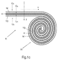
- the term “roll” or “roll of adhesive tape” is commonly used, even if strictly speaking the wraps are an Archimedean spiral. If in this document of roll, roll of adhesive tape, roll winding or winding is spoken, so hereby the winding of the adhesive tape is meant in such a way that the side section of the winding has the shape of an Archimedean spiral (see Figure 1c ).
- Particularly advantageous is such a roller winding, in which the wound-up adhesive tape is covered with a covering material, as has already been described above for the adhesive tape itself.
- the invention further provides a method for the flying reel change using an adhesive tape according to the invention.
- the inventive method for connecting two flat webs during the flying role change of wound on rolls flat web material is shown schematically in the Figures 6a and 6b represented without wishing to be unnecessarily limited by the figure in the subject matter of the invention.
- the uppermost flat web winding (11) (in particular its end or its end region) of a new roll with an adhesive tape (K), comprising at least one separation system (TS) suitable for achieving a adhesive bond separable again klebe phytocardia on the underlying flat web winding ( 12), so that a part of a self-adhesive composition (M) required for joining to the expiring flat web (13) is exposed (cf. FIG. 6a ).
- the thus-equipped new roll is placed next to an almost completely unwound replacement old roll and accelerated to the substantially same rotational speed as this, then pressed against the old flat web (13), wherein the exposed self-adhesive (M) of the adhesive tape (K) glued to the old flat web (13) at substantially the same speeds of the webs, while at the same time the means of the separation system (TS) caused bonding of the uppermost flat web layer (end position of the winding) (11) on the underlying flat web layer (12) so flat separates, that after the separation process no adhesive areas are exposed, wherein an inventive adhesive tape is used.
- the separation process is effected by a splitting of the system carrier (T), wherein the adhesives (M O , M U ) are non-stickingly covered by the cleavage products (T 1 , T 2 ) of the nip carrier (T).
- the adhesive tape is glued at right angles to the current flat web.
- the bonding of the adhesive tape can also take place at an acute angle of up to 30 ° to the current flat web, in particular of up to 10 °.
- the separation process [separation of the bonding of the uppermost flat web layer (11) with the underlying flat web layer (12)] then takes place - in particular in the case of the adhesive tape adhered at right angles to the running flat web - transversely to the baseline, that is, the nip. or separation process begins in the maxima or maximum ranges of the right boundary edge (r TS ) of the separation system (TS) and extends in the direction of its minimum or minimum ranges, ie in the direction of the negative y-axis.
- the adhesive tape (K) is glued in a straight line under the end of the uppermost flat web layer (11) of a new flat web roll (or at a small distance from the end of the uppermost flat web winding) to the new flat web roll, so that a part of the adhesive tape (K) remains free, while the underside (U K ) of the adhesive tape by means of the separation system (TS) [in particular for the corresponding adhesive tape embodiments with the adhesive (M U ) of the separation system (TS); not shown here in detail] glued to the underlying flat web layer and thus the top layer position (especially the end of the top layer layer) ensures, where appropriate, initially only a part (A 2 ) of optionally on the self-adhesive (M) located cover (A) so that the part of the self-adhesive required for the splicing process is still covered with the cover (A 1 ) and the roll does not have a free adhesive surface in this state, whereupon the remaining cover (
- the flat webs are, in particular, paper webs and / or film webs and / or textile webs (woven, knitted or nonwoven webs or the like).
- the corresponding splitting force - depending on the material - can be perfectly adjusted and thus adapted to the requirement profile.
- the shape or geometry of the respective segment should advantageously require the smallest possible force for splitting in the transverse direction of the adhesive tape (y-direction). However, this should not be too low, so as not to open too early in the acceleration phase of the bale and thus lead to a demolition. This is especially true for belt-driven systems where a special strength is required in the area of the belt.
- the segments mentioned are provided transversely to the unwinding direction of the adhesive tape with the smallest possible pitch, so that the tendency to pinch is minimized.
- the adhesive tape according to the invention has proved to be outstandingly suitable for the intended use.
Applications Claiming Priority (2)
| Application Number | Priority Date | Filing Date | Title |
|---|---|---|---|
| DE102008026448 | 2008-06-03 | ||
| DE102008060181A DE102008060181A1 (de) | 2008-06-03 | 2008-11-27 | Klebeband und seine Verwendung |
Publications (2)
| Publication Number | Publication Date |
|---|---|
| EP2130888A2 true EP2130888A2 (fr) | 2009-12-09 |
| EP2130888A3 EP2130888A3 (fr) | 2013-12-25 |
Family
ID=41026388
Family Applications (1)
| Application Number | Title | Priority Date | Filing Date |
|---|---|---|---|
| EP09161859.5A Withdrawn EP2130888A3 (fr) | 2008-06-03 | 2009-06-03 | Bande adhésive et son utilisationRuban adhésif de raccordement volant |
Country Status (5)
| Country | Link |
|---|---|
| US (1) | US8343605B2 (fr) |
| EP (1) | EP2130888A3 (fr) |
| JP (1) | JP5554017B2 (fr) |
| KR (1) | KR101598444B1 (fr) |
| DE (1) | DE102008060181A1 (fr) |
Cited By (2)
| Publication number | Priority date | Publication date | Assignee | Title |
|---|---|---|---|---|
| DE102015222282A1 (de) | 2015-11-12 | 2017-05-18 | Tesa Se | Klebeband und seine Verwendung |
| WO2021122227A1 (fr) | 2019-12-20 | 2021-06-24 | Tesa Se | Adhésif approprié pour un changement de rouleau à la volée de matériaux à surfaces à faible énergie |
Families Citing this family (5)
| Publication number | Priority date | Publication date | Assignee | Title |
|---|---|---|---|---|
| DE102008059381A1 (de) * | 2008-06-03 | 2009-12-17 | Tesa Se | Klebeband und seine Verwendung |
| DE102008059385A1 (de) * | 2008-06-03 | 2009-12-10 | Tesa Se | Klebeband und seine Verwendung |
| US20100242559A1 (en) * | 2009-03-24 | 2010-09-30 | Saenz De Miera Vicente Martin | Method of producing aluminum products |
| GB2523785B (en) * | 2014-03-05 | 2017-02-22 | Itw Ltd | Adhesive roll |
| JP6968077B2 (ja) * | 2016-01-29 | 2021-11-17 | スリーエム イノベイティブ プロパティズ カンパニー | 印刷可能な接着剤組成物によるウェブ縁部処理を伴うウェブ巻取りロール |
Citations (7)
| Publication number | Priority date | Publication date | Assignee | Title |
|---|---|---|---|---|
| US5323981A (en) | 1991-12-13 | 1994-06-28 | Sequa Corporation | Splicer tape system |
| WO1995029115A1 (fr) | 1994-04-26 | 1995-11-02 | Minnesota Mining And Manufacturing Company | Bande de raccord, procede de raccord et raccord a l'aide de cette bande |
| DE19628317A1 (de) | 1996-07-13 | 1998-01-15 | Beiersdorf Ag | Klebeband und Verfahren zu seiner Verwendung |
| DE19841609A1 (de) | 1998-09-11 | 2000-03-16 | Peter Prinz | Haftelement oder -streifen für Fliegenden Rollenwechsel |
| DE19902179A1 (de) | 1999-01-21 | 2000-08-03 | Beiersdorf Ag | Klebeband |
| DE10058956A1 (de) | 2000-11-28 | 2002-06-06 | Tesa Ag | Klebeband |
| DE102005051181A1 (de) | 2005-10-24 | 2007-04-26 | Tesa Ag | Spaltfreudiges Klebeband, seine Verwendung und Werkzeug zu seiner Herstellung |
Family Cites Families (10)
| Publication number | Priority date | Publication date | Assignee | Title |
|---|---|---|---|---|
| ES2105063T3 (es) * | 1990-04-03 | 1997-10-16 | Voith Gmbh J M | Dispositivo para la aplicacion de una cinta adhesiva sobre un arrollamiento de banda. |
| DE19958223A1 (de) * | 1999-12-02 | 2001-07-19 | Beiersdorf Ag | Klebeband |
| DE10029298A1 (de) * | 2000-06-14 | 2002-01-03 | Beiersdorf Ag | Befestigungsetikett |
| DE10123981A1 (de) | 2001-05-17 | 2003-01-23 | Tesa Ag | Klebeband |
| CA2454692C (fr) * | 2001-08-29 | 2008-12-02 | Tesa Ag | Bande adhesive detectable par machine |
| DE10210192A1 (de) * | 2002-03-07 | 2003-10-09 | Tesa Ag | Klebeband für fliegenden Rollenwechsel |
| ATE418515T1 (de) * | 2003-12-21 | 2009-01-15 | 3M Innovative Properties Co | Maschinell erkennbares band zum stossverbinden |
| DE102004040814A1 (de) * | 2004-08-24 | 2006-03-02 | Tesa Ag | Klebeband zur Herstellung einer Splice-Verbindung |
| DE102004048880A1 (de) * | 2004-10-06 | 2006-04-13 | Tesa Ag | Klebeband zur Herstellung einer Verbindung bei einem statischen Rollenwechsel |
| DE102006003200A1 (de) * | 2006-01-24 | 2007-08-02 | Bhs Corrugated Maschinen- Und Anlagenbau Gmbh | Verfahren zum Splicen von Material-Bahnen und Splice-Vorrichtung |
-
2008
- 2008-11-27 DE DE102008060181A patent/DE102008060181A1/de not_active Withdrawn
-
2009
- 2009-05-29 US US12/474,516 patent/US8343605B2/en not_active Expired - Fee Related
- 2009-06-02 JP JP2009132672A patent/JP5554017B2/ja not_active Expired - Fee Related
- 2009-06-03 KR KR1020090048986A patent/KR101598444B1/ko active IP Right Grant
- 2009-06-03 EP EP09161859.5A patent/EP2130888A3/fr not_active Withdrawn
Patent Citations (8)
| Publication number | Priority date | Publication date | Assignee | Title |
|---|---|---|---|---|
| US5323981A (en) | 1991-12-13 | 1994-06-28 | Sequa Corporation | Splicer tape system |
| WO1995029115A1 (fr) | 1994-04-26 | 1995-11-02 | Minnesota Mining And Manufacturing Company | Bande de raccord, procede de raccord et raccord a l'aide de cette bande |
| EP0757657A1 (fr) | 1994-04-26 | 1997-02-12 | Minnesota Mining And Manufacturing Company | Bande de raccord, procede de raccord et raccord a l'aide de cette bande |
| DE19628317A1 (de) | 1996-07-13 | 1998-01-15 | Beiersdorf Ag | Klebeband und Verfahren zu seiner Verwendung |
| DE19841609A1 (de) | 1998-09-11 | 2000-03-16 | Peter Prinz | Haftelement oder -streifen für Fliegenden Rollenwechsel |
| DE19902179A1 (de) | 1999-01-21 | 2000-08-03 | Beiersdorf Ag | Klebeband |
| DE10058956A1 (de) | 2000-11-28 | 2002-06-06 | Tesa Ag | Klebeband |
| DE102005051181A1 (de) | 2005-10-24 | 2007-04-26 | Tesa Ag | Spaltfreudiges Klebeband, seine Verwendung und Werkzeug zu seiner Herstellung |
Cited By (4)
| Publication number | Priority date | Publication date | Assignee | Title |
|---|---|---|---|---|
| DE102015222282A1 (de) | 2015-11-12 | 2017-05-18 | Tesa Se | Klebeband und seine Verwendung |
| EP3173452A1 (fr) | 2015-11-12 | 2017-05-31 | tesa SE | Bande adhésive et son utilisation |
| US10858209B2 (en) | 2015-11-12 | 2020-12-08 | Tesa Se | Adhesive tape and its use |
| WO2021122227A1 (fr) | 2019-12-20 | 2021-06-24 | Tesa Se | Adhésif approprié pour un changement de rouleau à la volée de matériaux à surfaces à faible énergie |
Also Published As
| Publication number | Publication date |
|---|---|
| JP5554017B2 (ja) | 2014-07-23 |
| EP2130888A3 (fr) | 2013-12-25 |
| US20090294054A1 (en) | 2009-12-03 |
| US8343605B2 (en) | 2013-01-01 |
| KR20090126207A (ko) | 2009-12-08 |
| KR101598444B1 (ko) | 2016-02-29 |
| DE102008060181A1 (de) | 2009-12-10 |
| JP2009293026A (ja) | 2009-12-17 |
Similar Documents
| Publication | Publication Date | Title |
|---|---|---|
| EP2130887B1 (fr) | Ruban adhésif de raccordement volant | |
| EP2130889B1 (fr) | Ruban adhésif de raccordement volant | |
| EP2130888A2 (fr) | Bande adhésive et son utilisationRuban adhésif de raccordement volant | |
| EP1355843B1 (fr) | Bande adhesive destinee au remplacement de rouleau automatique | |
| EP1423322B1 (fr) | Bande adhesive detectable par machine | |
| EP2130886B1 (fr) | Ruban adhésif de raccordement volant | |
| EP1342684A2 (fr) | Ruban adhésif pour raccordement volant | |
| EP1432631B1 (fr) | Bande adhesive detectable par machine | |
| EP1630116B1 (fr) | Ruban adhésif pour joint de raccordement | |
| EP2113543B1 (fr) | Ruban adhésif de raccordement volant | |
| EP1423320B1 (fr) | Bande adhesive detectable par machine | |
| EP3124565A1 (fr) | Bande adhésive pour le changement de bobine mobile | |
| EP2048212B1 (fr) | Bande adhésive pour le changement de rouleau mobile | |
| EP1640301B1 (fr) | Ruban adhésif pour la réalisation d'un raccordement à la volée avec un système clivable pendant le changement d'un rouleau. | |
| EP2571949B1 (fr) | Bande adhésive de collure comprenant deux éléments de liaison fendables | |
| EP1104795B1 (fr) | Ruban adhésif | |
| EP1423321B1 (fr) | Bande adhesive detectable par machine | |
| EP1429984B1 (fr) | Ruban adhesif con u pour le remplacement automatique de rouleaux | |
| EP1076026B1 (fr) | Ruban de raccordement avec une aide de fixation et son utilisation | |
| EP1604927A1 (fr) | Bande adhésive et son utilisation | |
| EP1436220B1 (fr) | Bande adhesive pour adherence continue sur une calandre | |
| EP1645533B1 (fr) | Ruban adhésif pour relier les rouleaux lors d'un échange | |
| DE202013103170U1 (de) | Perforiertes Klebeband | |
| EP3719092B1 (fr) | Bande adhésive et matériau en bande continu plate doté d'une telle bande adhésive | |
| EP1432632B1 (fr) | Bande de protection |
Legal Events
| Date | Code | Title | Description |
|---|---|---|---|
| PUAI | Public reference made under article 153(3) epc to a published international application that has entered the european phase |
Free format text: ORIGINAL CODE: 0009012 |
|
| AK | Designated contracting states |
Kind code of ref document: A2 Designated state(s): AT BE BG CH CY CZ DE DK EE ES FI FR GB GR HR HU IE IS IT LI LT LU LV MC MK MT NL NO PL PT RO SE SI SK TR |
|
| PUAL | Search report despatched |
Free format text: ORIGINAL CODE: 0009013 |
|
| AK | Designated contracting states |
Kind code of ref document: A3 Designated state(s): AT BE BG CH CY CZ DE DK EE ES FI FR GB GR HR HU IE IS IT LI LT LU LV MC MK MT NL NO PL PT RO SE SI SK TR |
|
| RIC1 | Information provided on ipc code assigned before grant |
Ipc: C09J 7/02 20060101AFI20131121BHEP Ipc: B65H 19/10 20060101ALI20131121BHEP |
|
| 17P | Request for examination filed |
Effective date: 20140625 |
|
| RBV | Designated contracting states (corrected) |
Designated state(s): AT BE BG CH CY CZ DE DK EE ES FI FR GB GR HR HU IE IS IT LI LT LU LV MC MK MT NL NO PL PT RO SE SI SK TR |
|
| RAP1 | Party data changed (applicant data changed or rights of an application transferred) |
Owner name: TESA SE |
|
| STAA | Information on the status of an ep patent application or granted ep patent |
Free format text: STATUS: EXAMINATION IS IN PROGRESS |
|
| 17Q | First examination report despatched |
Effective date: 20171124 |
|
| STAA | Information on the status of an ep patent application or granted ep patent |
Free format text: STATUS: THE APPLICATION IS DEEMED TO BE WITHDRAWN |
|
| 18D | Application deemed to be withdrawn |
Effective date: 20180405 |