EP1429984B1 - Ruban adhesif con u pour le remplacement automatique de rouleaux - Google Patents
Ruban adhesif con u pour le remplacement automatique de rouleaux Download PDFInfo
- Publication number
- EP1429984B1 EP1429984B1 EP01976237A EP01976237A EP1429984B1 EP 1429984 B1 EP1429984 B1 EP 1429984B1 EP 01976237 A EP01976237 A EP 01976237A EP 01976237 A EP01976237 A EP 01976237A EP 1429984 B1 EP1429984 B1 EP 1429984B1
- Authority
- EP
- European Patent Office
- Prior art keywords
- adhesive
- self
- paper
- adhesive tape
- roll
- Prior art date
- Legal status (The legal status is an assumption and is not a legal conclusion. Google has not performed a legal analysis and makes no representation as to the accuracy of the status listed.)
- Revoked
Links
Images


Classifications
-
- B—PERFORMING OPERATIONS; TRANSPORTING
- B65—CONVEYING; PACKING; STORING; HANDLING THIN OR FILAMENTARY MATERIAL
- B65H—HANDLING THIN OR FILAMENTARY MATERIAL, e.g. SHEETS, WEBS, CABLES
- B65H19/00—Changing the web roll
- B65H19/10—Changing the web roll in unwinding mechanisms or in connection with unwinding operations
- B65H19/102—Preparing the leading end of the replacement web before splicing operation; Adhesive arrangements on leading end of replacement web; Tabs and adhesive tapes for splicing
-
- C—CHEMISTRY; METALLURGY
- C09—DYES; PAINTS; POLISHES; NATURAL RESINS; ADHESIVES; COMPOSITIONS NOT OTHERWISE PROVIDED FOR; APPLICATIONS OF MATERIALS NOT OTHERWISE PROVIDED FOR
- C09J—ADHESIVES; NON-MECHANICAL ASPECTS OF ADHESIVE PROCESSES IN GENERAL; ADHESIVE PROCESSES NOT PROVIDED FOR ELSEWHERE; USE OF MATERIALS AS ADHESIVES
- C09J7/00—Adhesives in the form of films or foils
- C09J7/20—Adhesives in the form of films or foils characterised by their carriers
- C09J7/29—Laminated material
-
- B—PERFORMING OPERATIONS; TRANSPORTING
- B65—CONVEYING; PACKING; STORING; HANDLING THIN OR FILAMENTARY MATERIAL
- B65H—HANDLING THIN OR FILAMENTARY MATERIAL, e.g. SHEETS, WEBS, CABLES
- B65H2301/00—Handling processes for sheets or webs
- B65H2301/40—Type of handling process
- B65H2301/41—Winding, unwinding
- B65H2301/417—Handling or changing web rolls
- B65H2301/4176—Preparing leading edge of replacement roll
- B65H2301/41766—Preparing leading edge of replacement roll by adhesive tab or tape with cleavable or delaminating layer
-
- B—PERFORMING OPERATIONS; TRANSPORTING
- B65—CONVEYING; PACKING; STORING; HANDLING THIN OR FILAMENTARY MATERIAL
- B65H—HANDLING THIN OR FILAMENTARY MATERIAL, e.g. SHEETS, WEBS, CABLES
- B65H2301/00—Handling processes for sheets or webs
- B65H2301/40—Type of handling process
- B65H2301/46—Splicing
- B65H2301/4606—Preparing leading edge for splicing
- B65H2301/4607—Preparing leading edge for splicing by adhesive tape
-
- B—PERFORMING OPERATIONS; TRANSPORTING
- B65—CONVEYING; PACKING; STORING; HANDLING THIN OR FILAMENTARY MATERIAL
- B65H—HANDLING THIN OR FILAMENTARY MATERIAL, e.g. SHEETS, WEBS, CABLES
- B65H2301/00—Handling processes for sheets or webs
- B65H2301/40—Type of handling process
- B65H2301/46—Splicing
- B65H2301/4606—Preparing leading edge for splicing
- B65H2301/46078—Preparing leading edge for splicing the adhesive tab or tab having a cleavable or delaminating layer
-
- B—PERFORMING OPERATIONS; TRANSPORTING
- B65—CONVEYING; PACKING; STORING; HANDLING THIN OR FILAMENTARY MATERIAL
- B65H—HANDLING THIN OR FILAMENTARY MATERIAL, e.g. SHEETS, WEBS, CABLES
- B65H2557/00—Means for control not provided for in groups B65H2551/00 - B65H2555/00
- B65H2557/10—Means for control not provided for in groups B65H2551/00 - B65H2555/00 for signal transmission
- B65H2557/13—Data carrier, e.g. chip, transponder, magnetic strip
-
- C—CHEMISTRY; METALLURGY
- C09—DYES; PAINTS; POLISHES; NATURAL RESINS; ADHESIVES; COMPOSITIONS NOT OTHERWISE PROVIDED FOR; APPLICATIONS OF MATERIALS NOT OTHERWISE PROVIDED FOR
- C09J—ADHESIVES; NON-MECHANICAL ASPECTS OF ADHESIVE PROCESSES IN GENERAL; ADHESIVE PROCESSES NOT PROVIDED FOR ELSEWHERE; USE OF MATERIALS AS ADHESIVES
- C09J2203/00—Applications of adhesives in processes or use of adhesives in the form of films or foils
- C09J2203/342—Applications of adhesives in processes or use of adhesives in the form of films or foils for flying splice applications
-
- C—CHEMISTRY; METALLURGY
- C09—DYES; PAINTS; POLISHES; NATURAL RESINS; ADHESIVES; COMPOSITIONS NOT OTHERWISE PROVIDED FOR; APPLICATIONS OF MATERIALS NOT OTHERWISE PROVIDED FOR
- C09J—ADHESIVES; NON-MECHANICAL ASPECTS OF ADHESIVE PROCESSES IN GENERAL; ADHESIVE PROCESSES NOT PROVIDED FOR ELSEWHERE; USE OF MATERIALS AS ADHESIVES
- C09J2400/00—Presence of inorganic and organic materials
- C09J2400/20—Presence of organic materials
- C09J2400/28—Presence of paper
- C09J2400/283—Presence of paper in the substrate
-
- Y—GENERAL TAGGING OF NEW TECHNOLOGICAL DEVELOPMENTS; GENERAL TAGGING OF CROSS-SECTIONAL TECHNOLOGIES SPANNING OVER SEVERAL SECTIONS OF THE IPC; TECHNICAL SUBJECTS COVERED BY FORMER USPC CROSS-REFERENCE ART COLLECTIONS [XRACs] AND DIGESTS
- Y10—TECHNICAL SUBJECTS COVERED BY FORMER USPC
- Y10T—TECHNICAL SUBJECTS COVERED BY FORMER US CLASSIFICATION
- Y10T428/00—Stock material or miscellaneous articles
- Y10T428/14—Layer or component removable to expose adhesive
-
- Y—GENERAL TAGGING OF NEW TECHNOLOGICAL DEVELOPMENTS; GENERAL TAGGING OF CROSS-SECTIONAL TECHNOLOGIES SPANNING OVER SEVERAL SECTIONS OF THE IPC; TECHNICAL SUBJECTS COVERED BY FORMER USPC CROSS-REFERENCE ART COLLECTIONS [XRACs] AND DIGESTS
- Y10—TECHNICAL SUBJECTS COVERED BY FORMER USPC
- Y10T—TECHNICAL SUBJECTS COVERED BY FORMER US CLASSIFICATION
- Y10T428/00—Stock material or miscellaneous articles
- Y10T428/28—Web or sheet containing structurally defined element or component and having an adhesive outermost layer
- Y10T428/2848—Three or more layers
Definitions
- the invention relates to an adhesive tape for the flying reel change of wound on rolls flat web material, equipped with a main carrier, a self-adhesive on the front and at least one adhesive fissile system on the back and their use.
- the flying reel change is a common method in paper mills or the like to replace an old, almost unwound roll of paper with a new, without having to stop the fast-running machines.
- a perforation of the uppermost paper layer and thus a targeted tearing of the paper web takes place at the perforation.
- the end of the old paper web becomes better with the beginning of the new paper web glued, in order to ensure a continuous operation as possible.
- Different types of bonding and preparation with different types of adhesive tape and splice geometries are known.
- DE 198 30 673 is to be regarded as the closest prior art and shows an adhesive tape for flying reel change in paper finishing machines or the like which has a paper carrier coated on both sides with a water-soluble self-adhesive. An edge region of the rear side of the adhesive tape is equipped with a single-sided adhesive tape, which in turn has a splittable paper backing.
- Another variant is described in DE 198 30 674. Here is an adhesive tape with two split strips shown.
- DE 199 02 179 A1 also shows an adhesive tape for a splicing method.
- This adhesive tape has a double-sided adhesive tape on its non-adhesive back side, which has a splittable paper carrier which splits during the splicing process and covers the respective adhesive.
- the laminated adhesive tape is arranged indented with a paper support made of split paper, namely at a certain distance from the longitudinal edge of the adhesive tape.
- the adhesive tapes according to the prior art show disadvantages. It is disadvantageous in the case of the above-mentioned adhesive tapes, in particular, that they must be glued under the uppermost paper web of a bale. This proves to be difficult in practice and, in particular, is poorly suited for automated attachment with machine assistance, an applicator or the like. Sticking instead of pasting is therefore desirable.
- the adhesive tape described in DE 198 30 673 must be glued flush with the front paper edge of the new paper roll, otherwise the self-adhesive on the underside of the main carrier glued to the second paper layer, which then leads to an uncontrolled opening and thus to tears.
- the object of the invention was therefore to provide an adhesive tape for the splicing process, which does not have the disadvantages of the prior art or only in a reduced manner, which is particularly suitable for automated application.
- claim 1 relates to an adhesive tape for the flying reel change of wound on rolls flat web material, equipped with a main carrier, a self-adhesive on the front, at least one adhesive fissile system and at least one non-splitting self-adhesive system on the back.
- the non-splitting self-adhesive system is preferably in the form of a strip.
- Non-splitting in this context refers to the function of this strip for the role change, as will be described in more detail below. Here, no cleavage of the non-splitting system should occur. Whether the system in principle is capable of splitting or not in other applications remains open.
- the inventive adhesive tape is glued with the non-splitting self-adhesive system on the bottom of the top paper web, in such a way that the paper edge is flush with the strip of self-adhesive system or slightly surmounted. Then the cleavable system is glued to the top of the second paper layer of the new paper roll. The paper edge terminates flush with the non-splitting self-adhesive system or lies between it and the splitting system. Thereafter, the cover is removed from the top side of the self-adhesive and the roll is prepared for the splice.
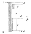
- the self-adherent, splittable system and the strip of the non-splitting self-adhesive system on the back of the adhesive tape have a distance L of at least 2 mm from each other, especially at least 3 mm, especially at least 5 mm. Due to the distance L, the adhesive tape or the non-splitting system does not have to be glued exactly flush with the front paper edge of the new paper roll; rather, to ensure proper operation, it is sufficient if the leading edge of the paper lies in the region of the distance L between the non-splitting system 10 and the splitting system 6.
- the cleavable system advantageously has a width (direction perpendicular to the longitudinal direction of the adhesive tape) of 3 to 50 mm, in particular from 6 to 40 mm, very particularly from 6 to 15 mm.
- the splittable system is engaged in the region of the front edge (longitudinal edge 14) of the adhesive tape, so that the main support projects beyond the splittable system on the side of the leading edge by a length E S , advantageously E S up to 15 mm, in particular 0, 5 to 15 mm, preferably 1 to 7 mm, very preferably 1.5 to 3.5 mm.
- a non-splitting self-adhesive system can be used in an excellent manner, a double-sided adhesive tape with or without support, alternatively, it is also advantageous to apply a self-adhesive in the streak.
- the maximum width B N (direction perpendicular to the longitudinal direction of the adhesive tape) of the non-splitting system results from the width B H of the main support, reduced by the width B S of the splitting system and the decor L, optionally additionally reduced by the indented lengths E S and E N.
- E N, B N, B is H
- B S E and S are optimized in relation to each other, in particular to a good bond over the self-adhesive 10 and a good operation of the cleaving system 6 to be ensured.
- a tear-resistant paper or film carrier is used as the main carrier.
- support materials may be mentioned here, for example: slightly creped papers, smooth board raw papers, coated on one side smooth base papers, coated on both sides, compacted, printable Decorepapiere, double-coated, wood-free, high-gloss Kraft papers, without wanting to restrict themselves unnecessarily by these examples in the choice of support materials ,
- the adhesive tape is equipped with at least one device which can be detected mechanically (contactless) by means of a detector, wherein the recognition is preferably achieved by metal, transponder systems or by optical devices.
- the main carrier (2) consists of a material to which at least one detectable additive is added, and / or the main carrier has at least one layer (X) of a detectable material.
- the inventive adhesive tape for example, metal powder or granules are admixed to the actual support material, or the support framework is provided with one or more metal layers.
- the integrated signal function is realized in such a way that the main carrier is provided on the top and / or on the bottom with an aluminum layer, and advantageously over its entire surface.
- aluminum it is also possible to use as layer all other materials which can be detected according to the requirements, in particular metals, for example copper, silver, gold.
- Such layers can be located independently of each other on both the front and on the back of the adhesive tape or the main carrier.
- the detection is caused by transponder systems, in particular by Dünn Anlagentranspondem, which are integrated into the tape.
- transponder systems in particular by Dünnlltranspondem
- the adhesive tape is provided with optically registrable means.
- These may be, for example, bar codes which can be read by a laser.
- additional information can be transmitted, for example information about the type or web thickness of the new roll.
- optical reflectors or diffraction gratings mounted in or on the main carrier of the adhesive tape function. These can also be optically detected and trigger the splicing process.
- Another example of optically detectable devices are certain colors of the main carrier, which can also be registered by suitable detection systems.
- the invention relates to a splicing method in which the uppermost paper web 11 of a roll is pasted over with an adhesive tape 1 by bonding the non-splitting system 10 located on the back side of the adhesive tape to the web end on the uppermost paper layer 11, while that on the back side of the Adhesive tape 1 located double-sided adhesive cleavable system 6 in turn with the underlying second paper web 12th glued and thus the top paper web 11 secures, initially the optionally located on the self-adhesive 3 release material 4 has not been deducted, so that the need for splicing part of the self-adhesive 3 is still covered with release material 4 and the paper roll in this state no free adhesive surface whereupon the optionally present separation material 4 is removed for the final preparation of the splicing process, whereupon the so-equipped new paper roll is placed next to an almost completely unwound, to be replaced old paper roll and is accelerated to the same rotational speed as this, then against the old paper web is pressed, wherein the
- the adhesive tape 1 is glued at right angles to the running paper web or at an acute angle of up to 30 °, in particular up to 10 °.
- the adhesive tape 1 is applied semiautomatically or fully automatically to the paper roll by means of a machine.
- the inventive adhesive tape 1 simplifies a machine, automated application to new roles to prepare the splicing process.
- FIG. 1 shows an adhesive tape 1 with a main carrier 2 made of weakly creped kraft paper, coated on one side with a water-soluble self-adhesive composition 3.
- the total thickness of the main carrier 2 with self-adhesive composition 3 is 0.115 mm, the width 75 mm.
- the self-adhesive composition 3 is covered with a siliconized release paper 4.
- a strip of double-sided adhesive tape 6 is pasted, consisting of a paper support 7 made of split paper, coated on both sides with water-soluble self-adhesive composition 8 or 9.
- the adhesive tape 6 has a Width of 12 mm.
- At the left end of a strip of self-adhesive 10 is laminated, which in this case also has a width of 12 mm.
- the main carrier 2 shows an adhesive tape 1 with a main carrier 2, coated on one side with a water-soluble self-adhesive composition 3, corresponding to FIG. 1.
- the main carrier 2 here consists of a composite of weakly creped kraft paper and aluminum.
- an aluminum layer X is located on the front side of the main carrier 2 (between the main carrier 2 and the self-adhesive layer 3).
- the total thickness of the main carrier 2 with self-adhesive 3 is 0.115 mm, the width 75 mm.
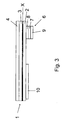
- FIG 3 is shown how an inventive adhesive tape 1 is glued to a (new) paper roll, with the left part 10 on the end of the uppermost paper layer 11 and the right part 7 on the top of the underlying (second) layer 12 of the paper roll.
- the release paper 4 can be deducted from the top of the adhesive tape 1, so that the paper roll thus equipped is ready for a flying reel change, wherein the bonding of the adhesive tape 1 at right angles passes over the roller.
- the self-adhesive composition 3 is open at this moment and represents the contact surface with the running web of the preceding roll for the flying roll change.
- the contact surface has a width of 75 mm and extends over the entire width of the paper roll.
- the (new) paper roll thus equipped is brought next to the almost unwound (old) paper roll to which the new one is to be applied.
- the new roll of paper is accelerated to a rotational speed close to the speed of the trajectory. If both speeds are sufficiently synchronized, the change can take place:
- the running web is brought into contact with the circumference of the new roll by means of a pressure wave and the self-adhesive 3 according to FIG. 4 is glued to the running paper web 13 of the old roll.
- both self-adhesives 8 and 9 are effectively neutralized, no longer stick and thus do not interfere with the further process in the paper processing machines.
- the new roll of paper is firmly connected to the running web with the self-adhesive 3, which was glued on the uppermost layer of the paper roll.
Claims (9)
- Ruban adhésif pour le remplacement à la volée de rouleaux d'un matériau en bande plane enroulé en rouleaux, doté d'un support principal (2), d'une pâte autoadhésive (3) sur son côté avant et d'au moins un système autoadhésif revendable (6) sur son côté arrière, caractérisé en ce qu'au moins un système autoadhésif non refendable (10) est en outre prévu sur le côté arrière, en ce que le système refendable (6) est constitué de papier, d'un film ou d'un composite de papiers, de films ou de papiers avec des films et est doté d'une pâte autoadhésive des deux côtés.
- Ruban adhésif selon la revendication 1,
caractérisé en ce que le système autoadhésif refendable (6) prévu sur le côté arrière et le système autoadhésif non refendable (10) prévu sur le côté arrière présentent un écart L d'au moins 2 mm, en particulier d'au moins 3 mm et de façon tout particulièrement préférable d'au moins 5 mm. - Ruban adhésif selon au moins l'une des revendications précédentes, caractérisé en ce que le système autoadhésif non refendable (10) est un ruban adhésif double face doté ou non d'un support.
- Ruban adhésif selon au moins l'une des revendications 1 ou 2, caractérisé en ce que le système autoadhésif non refendable (10) est une pâte autoadhésive appliquée en cordon.
- Ruban adhésif selon au moins l'une des revendications précédentes, caractérisé en ce que la pâte autoadhésive (10) prévue sur le côté arrière a une haute résistance au cisaillement, et présente en particulier une résistance au cisaillement, mesurée à 23°C et 55% d'humidité relative de l'air sous une charge de 1 kg, d'au moins plus de 1 000 minutes sur un papier couché brut et plus de 2 000 minutes sur un papier d'héliogravure.
- Ruban adhésif selon au moins l'une des revendications précédentes, caractérisé par au moins un dispositif (X) qui peut être détecté à la machine au moyen d'un détecteur, la détection étant obtenue en particulier à l'aide d'un métal, d'un transpondeur ou de dispositifs optiques.
- Procédé de raccordement dans lequel un ruban adhésif (1) selon au moins l'une des revendications 1 à 7 est collé sur la couche supérieure de papier d'un rouleau, en collant le système non refendable (10) situé sur le côté arrière du ruban adhésif (1) sur l'extrémité de la couche supérieure (11) de papier, tandis que le système adhésif double face refendable (6) situé sur le côté arrière du ruban adhésif est collé pour sa part sur la deuxième bande de papier (12) située en dessous de la première, pour ainsi immobiliser la couche supérieure (11) de papier, le matériau de séparation (4) éventuellement situé sur la pâte autoadhésive (3) n'étant d'abord pas enlevé, de telle sorte que la partie de la pâte autoadhésive (3) nécessaire pour le procédé de raccordement reste encore recouverte du matériau de séparation (4) et que dans cet état, le rouleau de papier ne présente pas de surface adhésive libre, suite à quoi, pour terminer la préparation de l'opération de raccordement, le matériau de séparation (4) éventuellement encore présent est enlevé pour placer ensuite le nouveau rouleau de papier ainsi apprêté à côté d'un ancien rouleau de papier presque complètement épuisé et à l'accélérer à la même vitesse de rotation que ce dernier, le repousser ensuite contre l'ancienne bande de papier (13), la pâte autoadhésive (3) exposée du ruban adhésif (1) étant collée sur l'ancienne bande de papier (13) lorsque les vitesses des bandes de papier sont essentiellement égales, tandis qu'en même temps le support (7) du système refendable (6) se refend et que les deux pâtes autoadhésives (8, 9) dont il est enduit sont recouvertes de par ses résidus (7a, 7b) en étant ainsi rendues non adhésives.
- Procédé de raccordement selon la revendication 7, caractérisé en ce que le ruban adhésif (1) est collé perpendiculairement à la bande de papier en déplacement ou à un angle aigu d'au plus 30° et en particulier d'au plus 10°.
- Procédé de raccordement selon au moins l'une des revendications 7 ou 8, caractérisé en ce que le ruban adhésif (1) est appliqué sur le rouleau de papier de manière semi-automatique ou entièrement automatique, au moyen d'un automate.
Applications Claiming Priority (1)
| Application Number | Priority Date | Filing Date | Title |
|---|---|---|---|
| PCT/EP2001/010822 WO2003024850A1 (fr) | 2001-09-19 | 2001-09-19 | Ruban adhesif conçu pour le remplacement automatique de rouleaux |
Publications (2)
| Publication Number | Publication Date |
|---|---|
| EP1429984A1 EP1429984A1 (fr) | 2004-06-23 |
| EP1429984B1 true EP1429984B1 (fr) | 2006-04-26 |
Family
ID=8164594
Family Applications (1)
| Application Number | Title | Priority Date | Filing Date |
|---|---|---|---|
| EP01976237A Revoked EP1429984B1 (fr) | 2001-09-19 | 2001-09-19 | Ruban adhesif con u pour le remplacement automatique de rouleaux |
Country Status (8)
| Country | Link |
|---|---|
| US (3) | US20050103429A1 (fr) |
| EP (1) | EP1429984B1 (fr) |
| JP (1) | JP2005503305A (fr) |
| AT (1) | ATE324342T1 (fr) |
| CA (1) | CA2458762A1 (fr) |
| DE (2) | DE10196895D2 (fr) |
| ES (1) | ES2261479T3 (fr) |
| WO (1) | WO2003024850A1 (fr) |
Families Citing this family (13)
| Publication number | Priority date | Publication date | Assignee | Title |
|---|---|---|---|---|
| DE10118362B4 (de) | 2001-04-12 | 2006-07-27 | Koenig & Bauer Ag | Verfahren zur Verbindung eines Bahnanfanges einer Materialrolle |
| DE102004028312A1 (de) * | 2004-06-11 | 2005-12-29 | Tesa Ag | Klebeband und seine Verwendung |
| DE102004048880A1 (de) * | 2004-10-06 | 2006-04-13 | Tesa Ag | Klebeband zur Herstellung einer Verbindung bei einem statischen Rollenwechsel |
| DE102007053432A1 (de) | 2007-11-07 | 2009-05-14 | Tesa Ag | Haftklebebänder für den Rollenwechsel von Flachbahnmaterialien |
| DE102008021247A1 (de) | 2008-04-28 | 2009-10-29 | Tesa Se | Klebeband für den Rollenwechsel von Flachbahnmaterialien |
| DE102008023020B4 (de) | 2008-05-09 | 2015-05-07 | Tesa Se | Klebeband für die Durchführung eines fliegenden Rollenwechsels |
| DE102008047966A1 (de) | 2008-09-18 | 2010-03-25 | Tesa Se | Repulpierbare Klebmassen |
| EP2433994B1 (fr) * | 2010-09-27 | 2013-12-25 | Illinois Tool Works Inc. | Ruban adhésif et son procédé de fabrication |
| JP2013010615A (ja) * | 2011-06-30 | 2013-01-17 | Nippon Paper Industries Co Ltd | 巻取紙自動仕立用接続テープ及び巻取紙の紙継ぎ方法 |
| US8877312B2 (en) * | 2012-12-11 | 2014-11-04 | Chung-Chin Wang | Flying splices tape |
| DE102015214193A1 (de) | 2015-07-27 | 2017-02-02 | Tesa Se | Klebeband für den fliegenden Rollenwechsel |
| DE102015222282A1 (de) | 2015-11-12 | 2017-05-18 | Tesa Se | Klebeband und seine Verwendung |
| CN112623377A (zh) * | 2020-10-30 | 2021-04-09 | 北京航星机器制造有限公司 | 一种胶带快速更换装置 |
Family Cites Families (12)
| Publication number | Priority date | Publication date | Assignee | Title |
|---|---|---|---|---|
| US3967994A (en) * | 1974-10-09 | 1976-07-06 | Langberg Associates, Inc. | Method of inspection for splices used for joining webs in a manufacturing process |
| US4588344A (en) * | 1984-06-04 | 1986-05-13 | Essex Group, Inc. | Roll transfer robot |
| US5323981A (en) * | 1991-12-13 | 1994-06-28 | Sequa Corporation | Splicer tape system |
| DE4210329A1 (de) * | 1992-03-30 | 1993-10-07 | Koenig & Bauer Ag | Anordnung zum Verbinden aufeinanderfolgender, zu Rollen gewickelter Papierbahnen |
| US5996927A (en) * | 1994-04-26 | 1999-12-07 | 3M Innovative Properties Company | Splicing tape, splicing method and splice using the splicing tape |
| JPH087521A (ja) * | 1994-06-17 | 1996-01-12 | Matsushita Electric Ind Co Ltd | テープカセット |
| DE19830674A1 (de) * | 1998-07-09 | 2000-01-13 | Beiersdorf Ag | Klebeband und seine Verwendung |
| DE19830673A1 (de) * | 1998-07-09 | 2000-01-13 | Beiersdorf Ag | Klebeband und seine Verwendung |
| DE19902179B4 (de) * | 1999-01-21 | 2005-04-28 | Tesa Ag | Klebeband und Spliceverfahren |
| US6140146A (en) * | 1999-08-03 | 2000-10-31 | Intermec Ip Corp. | Automated RFID transponder manufacturing on flexible tape substrates |
| DE10022483C1 (de) * | 2000-05-09 | 2001-11-29 | Siemens Ag | Spleißeinrichtung |
| US6808581B2 (en) * | 2001-06-15 | 2004-10-26 | 3M Innovative Properties Company | Method and apparatus for automatically applying a flying splicing tape to a roll of sheet material |
-
2001
- 2001-09-19 DE DE10196895T patent/DE10196895D2/de not_active Ceased
- 2001-09-19 ES ES01976237T patent/ES2261479T3/es not_active Expired - Lifetime
- 2001-09-19 JP JP2003528708A patent/JP2005503305A/ja active Pending
- 2001-09-19 AT AT01976237T patent/ATE324342T1/de not_active IP Right Cessation
- 2001-09-19 DE DE50109651T patent/DE50109651D1/de not_active Expired - Fee Related
- 2001-09-19 WO PCT/EP2001/010822 patent/WO2003024850A1/fr active IP Right Grant
- 2001-09-19 CA CA002458762A patent/CA2458762A1/fr not_active Abandoned
- 2001-09-19 EP EP01976237A patent/EP1429984B1/fr not_active Revoked
- 2001-09-19 US US10/490,124 patent/US20050103429A1/en not_active Abandoned
-
2006
- 2006-12-21 US US11/614,443 patent/US20070175569A1/en not_active Abandoned
-
2007
- 2007-02-06 US US11/671,824 patent/US20070128432A1/en not_active Abandoned
Also Published As
| Publication number | Publication date |
|---|---|
| DE50109651D1 (de) | 2006-06-01 |
| WO2003024850A1 (fr) | 2003-03-27 |
| US20050103429A1 (en) | 2005-05-19 |
| EP1429984A1 (fr) | 2004-06-23 |
| JP2005503305A (ja) | 2005-02-03 |
| DE10196895D2 (de) | 2004-08-05 |
| ES2261479T3 (es) | 2006-11-16 |
| US20070175569A1 (en) | 2007-08-02 |
| US20070128432A1 (en) | 2007-06-07 |
| CA2458762A1 (fr) | 2003-03-27 |
| ATE324342T1 (de) | 2006-05-15 |
Similar Documents
| Publication | Publication Date | Title |
|---|---|---|
| EP1022245B1 (fr) | Bande adhésive | |
| EP1423322B1 (fr) | Bande adhesive detectable par machine | |
| EP1355843B1 (fr) | Bande adhesive destinee au remplacement de rouleau automatique | |
| EP1432631B1 (fr) | Bande adhesive detectable par machine | |
| DE10210192A1 (de) | Klebeband für fliegenden Rollenwechsel | |
| EP1423320B1 (fr) | Bande adhesive detectable par machine | |
| EP1429984B1 (fr) | Ruban adhesif con u pour le remplacement automatique de rouleaux | |
| EP3124565A1 (fr) | Bande adhésive pour le changement de bobine mobile | |
| EP1258441B1 (fr) | Bande adhésive | |
| EP2571949B1 (fr) | Bande adhésive de collure comprenant deux éléments de liaison fendables | |
| EP2048212B1 (fr) | Bande adhésive pour le changement de rouleau mobile | |
| EP1104795B1 (fr) | Ruban adhésif | |
| EP1423321B1 (fr) | Bande adhesive detectable par machine | |
| EP1436220B1 (fr) | Bande adhesive pour adherence continue sur une calandre | |
| DE10123980B4 (de) | Abschlussbandage | |
| EP1645533B1 (fr) | Ruban adhésif pour relier les rouleaux lors d'un échange | |
| EP2509900B1 (fr) | Utilisation d'une bande d'épissage avec des bandes de masse de doublage disposées les unes à côté des autres | |
| DE10029298A1 (de) | Befestigungsetikett | |
| EP1327672A1 (fr) | Ruban adhésif pour le remplacement de rouleaux et utilisation du ruban adhésif |
Legal Events
| Date | Code | Title | Description |
|---|---|---|---|
| PUAI | Public reference made under article 153(3) epc to a published international application that has entered the european phase |
Free format text: ORIGINAL CODE: 0009012 |
|
| 17P | Request for examination filed |
Effective date: 20040419 |
|
| AK | Designated contracting states |
Kind code of ref document: A1 Designated state(s): AT BE CH CY DE DK ES FI FR GB GR IE IT LI LU MC NL PT SE TR |
|
| RAP1 | Party data changed (applicant data changed or rights of an application transferred) |
Owner name: TESA AG |
|
| RIN1 | Information on inventor provided before grant (corrected) |
Inventor name: GEBBEKEN, BERNHARD Inventor name: GASSNER, THOMAS Inventor name: EIKMEIER, MARKUS Inventor name: NAGEL, CHRISTOPH |
|
| 17Q | First examination report despatched |
Effective date: 20041207 |
|
| GRAP | Despatch of communication of intention to grant a patent |
Free format text: ORIGINAL CODE: EPIDOSNIGR1 |
|
| RIN1 | Information on inventor provided before grant (corrected) |
Inventor name: GASSNER, THOMAS Inventor name: NAGEL, CHRISTOPH Inventor name: EIKMEIER, MARKUS Inventor name: GEBBEKEN, BERNHARD |
|
| GRAS | Grant fee paid |
Free format text: ORIGINAL CODE: EPIDOSNIGR3 |
|
| GRAA | (expected) grant |
Free format text: ORIGINAL CODE: 0009210 |
|
| AK | Designated contracting states |
Kind code of ref document: B1 Designated state(s): AT BE CH CY DE DK ES FI FR GB GR IE IT LI LU MC NL PT SE TR |
|
| PG25 | Lapsed in a contracting state [announced via postgrant information from national office to epo] |
Ref country code: NL Free format text: LAPSE BECAUSE OF FAILURE TO SUBMIT A TRANSLATION OF THE DESCRIPTION OR TO PAY THE FEE WITHIN THE PRESCRIBED TIME-LIMIT Effective date: 20060426 Ref country code: IE Free format text: LAPSE BECAUSE OF FAILURE TO SUBMIT A TRANSLATION OF THE DESCRIPTION OR TO PAY THE FEE WITHIN THE PRESCRIBED TIME-LIMIT Effective date: 20060426 |
|
| REG | Reference to a national code |
Ref country code: GB Ref legal event code: FG4D Free format text: NOT ENGLISH |
|
| RIN1 | Information on inventor provided before grant (corrected) |
Inventor name: NAGEL, CHRISTOPH Inventor name: GASSNER, THOMAS Inventor name: GEBBEKEN, BERNHARD Inventor name: EIKMEIER, MARKUS |
|
| REG | Reference to a national code |
Ref country code: IE Ref legal event code: FG4D Free format text: LANGUAGE OF EP DOCUMENT: GERMAN |
|
| REF | Corresponds to: |
Ref document number: 50109651 Country of ref document: DE Date of ref document: 20060601 Kind code of ref document: P |
|
| GBT | Gb: translation of ep patent filed (gb section 77(6)(a)/1977) |
Effective date: 20060523 |
|
| PG25 | Lapsed in a contracting state [announced via postgrant information from national office to epo] |
Ref country code: DK Free format text: LAPSE BECAUSE OF FAILURE TO SUBMIT A TRANSLATION OF THE DESCRIPTION OR TO PAY THE FEE WITHIN THE PRESCRIBED TIME-LIMIT Effective date: 20060726 |
|
| REG | Reference to a national code |
Ref country code: SE Ref legal event code: TRGR |
|
| PGFP | Annual fee paid to national office [announced via postgrant information from national office to epo] |
Ref country code: AT Payment date: 20060914 Year of fee payment: 6 |
|
| PG25 | Lapsed in a contracting state [announced via postgrant information from national office to epo] |
Ref country code: PT Free format text: LAPSE BECAUSE OF FAILURE TO SUBMIT A TRANSLATION OF THE DESCRIPTION OR TO PAY THE FEE WITHIN THE PRESCRIBED TIME-LIMIT Effective date: 20060926 |
|
| PG25 | Lapsed in a contracting state [announced via postgrant information from national office to epo] |
Ref country code: MC Free format text: LAPSE BECAUSE OF NON-PAYMENT OF DUE FEES Effective date: 20060930 Ref country code: BE Free format text: LAPSE BECAUSE OF NON-PAYMENT OF DUE FEES Effective date: 20060930 Ref country code: CH Free format text: LAPSE BECAUSE OF NON-PAYMENT OF DUE FEES Effective date: 20060930 Ref country code: LI Free format text: LAPSE BECAUSE OF NON-PAYMENT OF DUE FEES Effective date: 20060930 |
|
| PGFP | Annual fee paid to national office [announced via postgrant information from national office to epo] |
Ref country code: DE Payment date: 20060930 Year of fee payment: 6 |
|
| NLV1 | Nl: lapsed or annulled due to failure to fulfill the requirements of art. 29p and 29m of the patents act | ||
| REG | Reference to a national code |
Ref country code: IE Ref legal event code: FD4D |
|
| REG | Reference to a national code |
Ref country code: ES Ref legal event code: FG2A Ref document number: 2261479 Country of ref document: ES Kind code of ref document: T3 |
|
| ET | Fr: translation filed | ||
| PLBI | Opposition filed |
Free format text: ORIGINAL CODE: 0009260 |
|
| PLAX | Notice of opposition and request to file observation + time limit sent |
Free format text: ORIGINAL CODE: EPIDOSNOBS2 |
|
| 26 | Opposition filed |
Opponent name: OY LINDELL AB Effective date: 20070118 |
|
| REG | Reference to a national code |
Ref country code: CH Ref legal event code: PL |
|
| PLAF | Information modified related to communication of a notice of opposition and request to file observations + time limit |
Free format text: ORIGINAL CODE: EPIDOSCOBS2 |
|
| PGFP | Annual fee paid to national office [announced via postgrant information from national office to epo] |
Ref country code: ES Payment date: 20070927 Year of fee payment: 7 |
|
| PGFP | Annual fee paid to national office [announced via postgrant information from national office to epo] |
Ref country code: FI Payment date: 20070913 Year of fee payment: 7 |
|
| BERE | Be: lapsed |
Owner name: TESA A.G. Effective date: 20060930 |
|
| PGFP | Annual fee paid to national office [announced via postgrant information from national office to epo] |
Ref country code: GB Payment date: 20070914 Year of fee payment: 7 |
|
| PLBB | Reply of patent proprietor to notice(s) of opposition received |
Free format text: ORIGINAL CODE: EPIDOSNOBS3 |
|
| PGFP | Annual fee paid to national office [announced via postgrant information from national office to epo] |
Ref country code: IT Payment date: 20070921 Year of fee payment: 7 Ref country code: SE Payment date: 20070913 Year of fee payment: 7 |
|
| PG25 | Lapsed in a contracting state [announced via postgrant information from national office to epo] |
Ref country code: GR Free format text: LAPSE BECAUSE OF FAILURE TO SUBMIT A TRANSLATION OF THE DESCRIPTION OR TO PAY THE FEE WITHIN THE PRESCRIBED TIME-LIMIT Effective date: 20060727 |
|
| PGFP | Annual fee paid to national office [announced via postgrant information from national office to epo] |
Ref country code: FR Payment date: 20070914 Year of fee payment: 7 |
|
| PG25 | Lapsed in a contracting state [announced via postgrant information from national office to epo] |
Ref country code: AT Free format text: LAPSE BECAUSE OF NON-PAYMENT OF DUE FEES Effective date: 20070919 |
|
| PG25 | Lapsed in a contracting state [announced via postgrant information from national office to epo] |
Ref country code: TR Free format text: LAPSE BECAUSE OF FAILURE TO SUBMIT A TRANSLATION OF THE DESCRIPTION OR TO PAY THE FEE WITHIN THE PRESCRIBED TIME-LIMIT Effective date: 20060426 Ref country code: LU Free format text: LAPSE BECAUSE OF NON-PAYMENT OF DUE FEES Effective date: 20060919 Ref country code: DE Free format text: LAPSE BECAUSE OF NON-PAYMENT OF DUE FEES Effective date: 20080401 |
|
| PG25 | Lapsed in a contracting state [announced via postgrant information from national office to epo] |
Ref country code: CY Free format text: LAPSE BECAUSE OF FAILURE TO SUBMIT A TRANSLATION OF THE DESCRIPTION OR TO PAY THE FEE WITHIN THE PRESCRIBED TIME-LIMIT Effective date: 20060426 |
|
| RAP2 | Party data changed (patent owner data changed or rights of a patent transferred) |
Owner name: TESA SE |
|
| GBPC | Gb: european patent ceased through non-payment of renewal fee |
Effective date: 20080919 |
|
| PG25 | Lapsed in a contracting state [announced via postgrant information from national office to epo] |
Ref country code: FI Free format text: LAPSE BECAUSE OF NON-PAYMENT OF DUE FEES Effective date: 20080919 |
|
| REG | Reference to a national code |
Ref country code: FR Ref legal event code: ST Effective date: 20090529 |
|
| PG25 | Lapsed in a contracting state [announced via postgrant information from national office to epo] |
Ref country code: IT Free format text: LAPSE BECAUSE OF NON-PAYMENT OF DUE FEES Effective date: 20080919 |
|
| PG25 | Lapsed in a contracting state [announced via postgrant information from national office to epo] |
Ref country code: FR Free format text: LAPSE BECAUSE OF NON-PAYMENT OF DUE FEES Effective date: 20080930 |
|
| REG | Reference to a national code |
Ref country code: ES Ref legal event code: FD2A Effective date: 20080920 |
|
| PG25 | Lapsed in a contracting state [announced via postgrant information from national office to epo] |
Ref country code: GB Free format text: LAPSE BECAUSE OF NON-PAYMENT OF DUE FEES Effective date: 20080919 |
|
| PG25 | Lapsed in a contracting state [announced via postgrant information from national office to epo] |
Ref country code: ES Free format text: LAPSE BECAUSE OF NON-PAYMENT OF DUE FEES Effective date: 20080920 |
|
| RDAF | Communication despatched that patent is revoked |
Free format text: ORIGINAL CODE: EPIDOSNREV1 |
|
| RDAG | Patent revoked |
Free format text: ORIGINAL CODE: 0009271 |
|
| STAA | Information on the status of an ep patent application or granted ep patent |
Free format text: STATUS: PATENT REVOKED |
|
| PG25 | Lapsed in a contracting state [announced via postgrant information from national office to epo] |
Ref country code: SE Free format text: LAPSE BECAUSE OF NON-PAYMENT OF DUE FEES Effective date: 20080920 |
|
| 27W | Patent revoked |
Effective date: 20080411 |