EP2130399B1 - Buffer transfer in a communications network - Google Patents
Buffer transfer in a communications network Download PDFInfo
- Publication number
- EP2130399B1 EP2130399B1 EP07727572A EP07727572A EP2130399B1 EP 2130399 B1 EP2130399 B1 EP 2130399B1 EP 07727572 A EP07727572 A EP 07727572A EP 07727572 A EP07727572 A EP 07727572A EP 2130399 B1 EP2130399 B1 EP 2130399B1
- Authority
- EP
- European Patent Office
- Prior art keywords
- data
- transfer
- base station
- buffer
- buffer data
- Prior art date
- Legal status (The legal status is an assumption and is not a legal conclusion. Google has not performed a legal analysis and makes no representation as to the accuracy of the status listed.)
- Not-in-force
Links
- 239000000872 buffer Substances 0.000 title claims description 95
- 238000012546 transfer Methods 0.000 title claims description 92
- 238000004891 communication Methods 0.000 title claims description 24
- 238000000034 method Methods 0.000 claims description 30
- 230000007246 mechanism Effects 0.000 claims description 12
- 230000005540 biological transmission Effects 0.000 claims description 9
- 230000015556 catabolic process Effects 0.000 claims description 3
- 238000006731 degradation reaction Methods 0.000 claims description 3
- 238000005259 measurement Methods 0.000 claims description 3
- 238000010295 mobile communication Methods 0.000 claims description 3
- 238000012360 testing method Methods 0.000 description 5
- 230000008859 change Effects 0.000 description 4
- 230000001627 detrimental effect Effects 0.000 description 2
- 230000000694 effects Effects 0.000 description 2
- 230000006855 networking Effects 0.000 description 2
- 238000005457 optimization Methods 0.000 description 2
- 230000001413 cellular effect Effects 0.000 description 1
- 230000001186 cumulative effect Effects 0.000 description 1
- 238000005516 engineering process Methods 0.000 description 1
- 230000007774 longterm Effects 0.000 description 1
- 238000012986 modification Methods 0.000 description 1
- 230000004048 modification Effects 0.000 description 1
- 230000008569 process Effects 0.000 description 1
- 239000000523 sample Substances 0.000 description 1
- 230000011664 signaling Effects 0.000 description 1
Images


Classifications
-
- H—ELECTRICITY
- H04—ELECTRIC COMMUNICATION TECHNIQUE
- H04W—WIRELESS COMMUNICATION NETWORKS
- H04W92/00—Interfaces specially adapted for wireless communication networks
- H04W92/16—Interfaces between hierarchically similar devices
- H04W92/20—Interfaces between hierarchically similar devices between access points
-
- H—ELECTRICITY
- H04—ELECTRIC COMMUNICATION TECHNIQUE
- H04W—WIRELESS COMMUNICATION NETWORKS
- H04W28/00—Network traffic management; Network resource management
- H04W28/02—Traffic management, e.g. flow control or congestion control
- H04W28/10—Flow control between communication endpoints
- H04W28/14—Flow control between communication endpoints using intermediate storage
-
- H—ELECTRICITY
- H04—ELECTRIC COMMUNICATION TECHNIQUE
- H04W—WIRELESS COMMUNICATION NETWORKS
- H04W36/00—Hand-off or reselection arrangements
- H04W36/08—Reselecting an access point
-
- H—ELECTRICITY
- H04—ELECTRIC COMMUNICATION TECHNIQUE
- H04W—WIRELESS COMMUNICATION NETWORKS
- H04W76/00—Connection management
- H04W76/10—Connection setup
Definitions
- the invention relates to buffer transfer in a communications network.
- a cellular mobile access network is a radio network made up of a number of cells, each cell being served by a fixed transmitter. Cells are used to cover different areas in order to provide radio coverage over a wider area than the area of one cell.
- the cells may comprise a Base Station, Radio Network Controller, or other similar device that has a downlink buffer. Data held in the downlink buffer at the old cell 102 must be transferred to the downlink buffer of the new cell 103.
- UDP User Datagram Protocol
- TCP Transmission Control Protocol
- Transport links will typically be shared between several base-station-to-base-station or base-station-to-anchor, etc. connections. Data traffic over the shared links may arrive from many different sources. It is therefore difficult to estimate the available capacity for a buffer transfer.
- TCP Stream Control Transmission Protocol
- SCTP Stream Control Transmission Protocol
- custom congestion-controlled UDP may solve the problem of sending buffer data at too high a rate, but these protocols require a large data overhead, making them inefficient for transferring buffer data.
- To establish a TCP connection takes too long a time (at least 2 round-trip times are needed before the actual buffer data can be sent).
- TCP requires a slow-start in order to reach the correct rate of data transfer. The result is that the handover interruption time would be dominated by such overheads and not radio protocols.
- the time required to set up a connection and speed up data transfer to the available rate is between 28-535ms, which is too large considering that the radio interruption should be of a shorter time.
- a semi-continuous transport connection is maintained between the base stations where buffer transfers may occur.
- This may be, for example, TCP or SCTP based.
- This connection is utilized whenever there is a need to perform buffer transfer. This way the time to establish a connection is eliminated (at least 2 round-trip times are otherwise required).
- Such connections are established and released on an on-demand basis, that is to say that if there is no buffer transfer between two base stations for some time, the connection is released.
- the transport protocol has no idea about the congestion state of the transport network, which would normally require measures such as additional extra round-trip times, possible retransmissions, losses, slow-start etc which are all detrimental to the performance of the network and the rate of data transfer between buffers.
- "dummy" packets are sent a short time before the buffer to buffer transfer starts.
- the dummy packets are sent with low priority, and their purpose is to continuously test the network for available capacity.
- the rate of the dummy packets on the application layer is preconfigured to maximize the occupied capacity of a single buffer transfer. A buffer transfer will therefore starts without data packet overheads, and at the maximum available rate.
- the dummy traffic has no or very little impact on real traffic.
- a method of transferring buffer data from a Base Station to a second Base Station during a mobile handover between cells comprising:
- the congestion control protocol may be selected from one of Transmission Control Protocol and Stream Control Transmission Protocol, although any suitable congestion control protocol may be used.
- the method may comprise receiving, at the first Base Station, an acknowledgement that all buffer data has been transferred to the second Base Station, and after receipt of the acknowledgement, sending dummy data from the first Base Station to the second Base Station.
- the method may comprise, prior to establishing the communication channel, determining when a buffer transfer will be required.
- This determination may be made on the basis of a trigger, the trigger being selected from one of a degradation in radio quality, a measurement command, policy control, and cross-layer communication
- the method may comprise, prior to transferring buffer data, establishing a communication channel between the first Base Station and a plurality of Base Stations, the plurality of Base Stations being possible target Base Stations for a handover. Once a target node has been selected for handover, the communications channel with the remaining nodes is closed.
- the method of transferring buffer data may comprise comprising calculating a length of time required for the dummy data to reach a data transfer capacity, and establishing the communication channel between the first and second Base Stations the calculated time before the handover.
- the time may be calculated on the basis of the sum of the time to establish the connection and the time to reach a data transfer rate capacity.
- the time to establish the connection may be calculated on the basis of the Round Trip Time.
- the time for the dummy data to reach a data transfer rate capacity is calculated on the basis of the Round Trip Time, the packet size, and the desired bitrate.
- a Base Station for use in a communications network, the Base Station comprising a transmitter, the transmitter arranged to transmit dummy data prior to a handover of a user terminal between cells in a mobile communications network via a channel that uses a congestion control protocol that uses a slow-start mechanism in order to increase the rate of data transfer using the slow-start mechanism, and the transmitter arranged to transmit buffer data after a handover.
- the Base Station also comprises a processor for scheduling transmission of dummy data and buffer data. The dummy data and buffer data is transmitted over a communication channel that uses a congestion control protocol;
- a semi-continuous transport connection is maintained between two nodes that may be involved in a buffer transfer.
- dummy data is sent over the connection to test the data transfer rate, and once the handover occurs the dummy data is replaced with actual buffer transfer data. Once the buffer transfer data has all been sent and acknowledged, dummy data is again sent over the connection to test the data transfer rate.
- each base station acts as a TPS as well as TPC entity.
- the buffer transfer transport connection established between selected base stations is called Buffer Transfer Transport Context (BTTC).
- BTTC Buffer Transfer Transport Context
- the TPS is responsible of maintaining a transport connection to the TPC.
- the used transport protocol can be configured or predefined, for example TCP or SCTP.
- BTTC is not established. If buffer transfer is starts and there is no BTTC present, a new BTTC is established by the TPC. This adds extra time to the initial handover, but the keep-alive timer is sufficiently large to keep the number of BTTC establishments low.
- the keep-alive timer is started. If the timer expires without any new real transfer data being sent, the BTTC is released and sending of dummy packets is stopped.
- the BTTC is established as part of a handover preparation. Usually, there is sufficient time before the actual handover happens to establish the BTTC and speed up the dummy rate during this time. There are several signals that may be used as a trigger for BTTC establishment, for example radio quality degradation, measurement command, policy control, cross-layer communication etc. The time needed to speed up the BTTC is short, so the amount of dummy packets can be kept low.
- the likely target cell has been identified before handover, then information is available about the likely target cell.
- the BTTC is established towards that cell and dummy traffic is only transmitted in that direction. For optimization reasons, this method is also applied it is determined statistically that certain targets or a particular target are more likely than others.
- a BTTC is established and dummy packets are be transmitted to all neighbouring cells or base stations which may be the recipient of the handover. Once the target cell has been identified, dummy traffic can be stopped to other cells or base stations.
- Figure 5 illustrates data transfer where BTTC is established as part of a handover preparation.
- dummy data is sent.
- the initial data transfer rate of dummy data is low, and the rate increases until the rate suitable for the capacity of the network is reached.
- the dummy data is replaced by real buffer transfer data. Because the rate suitable for the capacity of the network is known from sending the dummy data, the buffer transfer data is sent at the maximum suitable rate and does not require a slow-start mechanism.
- the buffer transfer data is replaced by dummy data.
- T speedup T connsetup + T slowstart
- T slowstart RTT TPS - TPC * log 2 ⁇ R / 8 / P SIZE * RTT TPS - TPC where R is the bitrate to achieve, and Psize is the packet size.
- the table below shows the total time required to speed up at different rates and RTT.
- RTT between TPS and TPC (sec) Rate (bps) 0.01 0.02 0.03 0.04 0.05 1000000 0.0287 0.0683 0.1142 0.1646 0.2185 5000000 0.0437 0.1044 0.1726 0.2457 0.3224 10000000 0.0522 0.1229 0.2010 0.2841 0.3708 20000000 0.0614 0.1420 0.2302 0.3232 0.4199 100000000 0.0840 0.1878 0.2991 0.4154 0.5353
- the buffer transfer can happen in an optimal way.
- the TPS tunnels the buffer data through the established connection with the DifTServ code-point configured for bluffer transfer data.
- the TPS application There may be some dummy packets in the transport protocol socket stored waiting for transmission or acknowledgement. As an optional optimization, the dummy packets that have not been transmitted can be deleted at this point.
- the TPS sends dummy packets with a rate limit configured and the dummy DiffServ code point.
- the rate limit is optional and it can be used to limit the amount of dummy traffic.
- the rate limit is also used to maintain a certain desired congestion window so that a buffer transfer after an idle period should work at the desired rate if capacity is available in the network.
- a network node 1001 is illustrated for use in a radio access network cell.
- the network node 1001 comprises a processor 1002 for generating dummy packets and scheduling the sending of dummy data packets and buffer data packets.
- a transmitter 1003 is also provided for sending the dummy data packets and the buffer data packets to another node.
- the network node in a radio access network is typically a Base Station.
- the TCP connection overhead does not impact buffer transfer; as data packets can be forwarded without delay.
- the speed-up time of 28-535 ms can be eliminated.
- the dummy traffic is estimated to be approximately 0.7-1 % of the subscriber traffic.
- the invention does not require a new transport protocol.
- TCP or SCTP can be used without changes.
- the networking devices between the two base stations can be off-the-shelf routers and switches with priority handling capabilities.
- the increased load on the network is controlled because the dummy traffic is rate limited. Furthermore, dummy traffic is only sent for a short time of around 60-600ms, and the load due to dummy traffic is negligible especially because it is sent at low priority. In case of processor congestion, dummy packets may be dropped to avoid impact on real traffic. Real data traffic is not impacted because dummy traffic is sent at low priority.
Description
- The invention relates to buffer transfer in a communications network.
- A cellular mobile access network is a radio network made up of a number of cells, each cell being served by a fixed transmitter. Cells are used to cover different areas in order to provide radio coverage over a wider area than the area of one cell.
- As shown in
Figure 1 , when a user withmobile equipment 101 moves between the areas covered byadjacent cells mobile equipment 101 and theold cell 102 is broken, and a new connection between themobile equipment 1 and a new cell 3 is established. The cells may comprise a Base Station, Radio Network Controller, or other similar device that has a downlink buffer. Data held in the downlink buffer at theold cell 102 must be transferred to the downlink buffer of thenew cell 103. - In 3G networks, this is solved by a special procedure and signalling standardized by 3GPP. In current 3G networks the buffer transfer procedure is done infrequently only when the user moves between Radio Network Controllers (RNCs). In future Long Term Evolution (LTE) technology, it is planned that this procedure will be done frequently because the packets are stored in the Base Stations (BSs) 104, 105, as illustrated in
Figure 1 , and will therefore be transferred between base stations during cell handover. - In mobile networks, when a cell change occurs, a buffer transfer may be required between the buffers of the involved base stations. Of course, the faster the transfer of buffer data between cells, the better and more "seamless" the user's experience will be. Possible solution for transferring data held in a buffer include possible solutions include User Datagram Protocol (UDP) or Transmission Control Protocol (TCP), but there are problems with using either of these protocols. Transport links will typically be shared between several base-station-to-base-station or base-station-to-anchor, etc. connections. Data traffic over the shared links may arrive from many different sources. It is therefore difficult to estimate the available capacity for a buffer transfer.
- The easiest solution is to use standard UDP and burst the data to the target base station at a high rate. Unfortunately the correct rate of this burst is unknown and if it is not estimated correctly, there may be many losses in the transfer. Furthermore, this technique may cause congestion for other connections sharing the same path. If for example, the error in the available rate estimation is just 10%, it will cause approximately 10% loss for the transmitted buffer data. This is a high amount for end-user applications, and is very detrimental to the performance as perceived by the end-user.
- TCP, Stream Control Transmission Protocol (SCTP), or custom congestion-controlled UDP may solve the problem of sending buffer data at too high a rate, but these protocols require a large data overhead, making them inefficient for transferring buffer data. To establish a TCP connection takes too long a time (at least 2 round-trip times are needed before the actual buffer data can be sent). Furthermore. TCP requires a slow-start in order to reach the correct rate of data transfer. The result is that the handover interruption time would be dominated by such overheads and not radio protocols. The time required to set up a connection and speed up data transfer to the available rate is between 28-535ms, which is too large considering that the radio interruption should be of a shorter time.
- An alternative solution is to use pre-established connections to save connection setup time. Keep-alive SCTP, TCP or custom congestion-controlled UDP solves the problem of the connection setup overhead, but when there is no data traffic for a period of time, assumptions made by these protocols about congestion is invalid and not within a guaranteed precision e.g., 10%. An implication of this is that there may be insufficient available capacity and packets may need to be re-transmitted, possibly causing long time-out and a slow-start. Furthermore, the Internet Engineering Task Force (IETF) suggests that if there is no traffic, the congestion window of TCP should be reduced to avoid overloading the available data paths. Again, this leads to the problem that a certain time needed to test for capacity starting from a low data transfer rate.
- As shown in
Figure 2 , using a TCP tunnel-based solution in a wireless emulation testbed shows that the speed of data transfer slows down considerably during handover, even though the radio handover time was set to zero ms (the data shown assumes a Round Trip Time, RTT, of 200ms, and a transfer rate of 5 Mbps). The x-axis shows time and the y-axis shows cumulative number of bytes transmitted. It can be seen that the slow-down lasts for around 2 seconds. The reason for the approximately 2 sec slow-down is that the transfer tunnel needs to test the available capacity to avoid Node-B-to-Node-B transport congestion. - Taleb et al., "A Dummy Segment Based Bandwidth Probing Technique to Enhance the Performance of TCP over Heterogeneous Networks", Wireless Communications and Networking Conference, 2005 IEEE 13-17 March 2005, pp2400-2405 is concerned with reducing problems caused by congestion and describes adjusting a sending rate on the basis of sending a burst of dummy packets to probe available bandwidth.
- Current buffer transfer mechanisms are not able to guarantee seamless handover at high data transfer speeds. Unlike in 3G, in the case of LTE or even 4G, the buffer transfer mechanism becomes a bottleneck during high-speed data transfers.
- According to the invention, between the base stations where buffer transfers may occur, a semi-continuous transport connection is maintained. This may be, for example, TCP or SCTP based. This connection is utilized whenever there is a need to perform buffer transfer. This way the time to establish a connection is eliminated (at least 2 round-trip times are otherwise required). Such connections are established and released on an on-demand basis, that is to say that if there is no buffer transfer between two base stations for some time, the connection is released.
- If there is no traffic over this connection for some time, the transport protocol has no idea about the congestion state of the transport network, which would normally require measures such as additional extra round-trip times, possible retransmissions, losses, slow-start etc which are all detrimental to the performance of the network and the rate of data transfer between buffers. To avoid this, "dummy" packets are sent a short time before the buffer to buffer transfer starts. The dummy packets are sent with low priority, and their purpose is to continuously test the network for available capacity. The rate of the dummy packets on the application layer is preconfigured to maximize the occupied capacity of a single buffer transfer. A buffer transfer will therefore starts without data packet overheads, and at the maximum available rate. The dummy traffic has no or very little impact on real traffic.
- According to a first aspect of the present invention, there is provided a method of transferring buffer data from a Base Station to a second Base Station during a mobile handover between cells, the method comprising:
- prior to transferring buffer data, establishing a communication channel between the first Base Station and the second Base Station, the communication channel using a congestion control protocol that uses a slow-start mechanism;
- sending dummy data from the first Base Station to the second Base Station using the communication channel in order to increase the rate of data transfer using the slow-start mechanism;
- at the handover, transferring the buffer data from the first Base Station to the second Base Station by sending buffer data in the place of dummy data.
- The congestion control protocol may be selected from one of Transmission Control Protocol and Stream Control Transmission Protocol, although any suitable congestion control protocol may be used.
- Once buffer data has been transferred, it may be desirable to send dummy data again to keep the channel open, in the event that further buffer data may need to be transferred. In this case, it is preferable to wait until all the buffer data has been transferred. Accordingly, the method may comprise receiving, at the first Base Station, an acknowledgement that all buffer data has been transferred to the second Base Station, and after receipt of the acknowledgement, sending dummy data from the first Base Station to the second Base Station.
- In order to minimize the amount of dummy data sent, the method may comprise, prior to establishing the communication channel, determining when a buffer transfer will be required.
- This determination may be made on the basis of a trigger, the trigger being selected from one of a degradation in radio quality, a measurement command, policy control, and cross-layer communication
- Where there are several possible Base Stations to which a possible handover may be directed, the method may comprise, prior to transferring buffer data, establishing a communication channel between the first Base Station and a plurality of Base Stations, the plurality of Base Stations being possible target Base Stations for a handover. Once a target node has been selected for handover, the communications channel with the remaining nodes is closed.
- To further minimize the amount of dummy data sent, the method of transferring buffer data may comprise comprising calculating a length of time required for the dummy data to reach a data transfer capacity, and establishing the communication channel between the first and second Base Stations the calculated time before the handover.
- The time may be calculated on the basis of the sum of the time to establish the connection and the time to reach a data transfer rate capacity. The time to establish the connection may be calculated on the basis of the Round Trip Time. Furthermore, the time for the dummy data to reach a data transfer rate capacity is calculated on the basis of the Round Trip Time, the packet size, and the desired bitrate.
- According to a second aspect of the invention, there is provided a Base Station for use in a communications network, the Base Station comprising a transmitter, the transmitter arranged to transmit dummy data prior to a handover of a user terminal between cells in a mobile communications network via a channel that uses a congestion control protocol that uses a slow-start mechanism in order to increase the rate of data transfer using the slow-start mechanism, and the transmitter arranged to transmit buffer data after a handover. The Base Station also comprises a processor for scheduling transmission of dummy data and buffer data. The dummy data and buffer data is transmitted over a communication channel that uses a congestion control protocol;
-
-
Figure 1 illustrates schematically buffer transfer between two cells in a mobile network during handover; -
Figure 2 is a graph illustrating the wireless emulation testbed data transfer with respect to time using a TCP based solution for buffer transfer; -
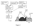
Figure 3 shows a flow chart illustrating the basic steps of the invention; -
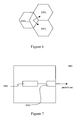
Figure 4 illustrates schematically buffer transfer between base stations; -
Figure 5 illustrates schematically transfer rate of dummy packets and buffer transfer data; -
Figure 6 illustrates schematically three adjacent base stations; and -
Figure 7 illustrates schematically a network node according to the present invention. - A semi-continuous transport connection is maintained between two nodes that may be involved in a buffer transfer. When a handover between the nodes is likely to occur, as illustrated in
Figure 3 , dummy data is sent over the connection to test the data transfer rate, and once the handover occurs the dummy data is replaced with actual buffer transfer data. Once the buffer transfer data has all been sent and acknowledged, dummy data is again sent over the connection to test the data transfer rate. - The invention requires the following components, as illustrated in
Figure 4 : - A transport protocol server (TPS) 401 including a transport protocol stack, a rate-controlled dummy packet sender, a priority setter and buffer transfer control
- Transport protocol client (TPC) 402; and
- Transport network equipment with standard transport level priority mechanism enabled (e.g., DiffServ)
- In a mobile communications network, each base station acts as a TPS as well as TPC entity. The buffer transfer transport connection established between selected base stations is called Buffer Transfer Transport Context (BTTC). A BTTC is defined by the following parameters:
- TPS identifier (IP address)
- TPC identifier (IP address)
- Anchor identifier, if the transferred buffer data is tunnelled through an anchor.
- Transport protocol type, which defines the transport protocol used. It can be either TCP, SCTP or any other transport protocol that uses congestion control and reliable transfer.
- Dummy rate defines the traffic rate used by the TPS to send dummy packets. It is possible to set this rate as infinite and allow the BTTC transport protocol to regulate the rate. Preferably the dummy rate is set to several megabits/second to maintain a certain startup rate for buffer transfer.
- Keep-alive timer, which defines how long the BTTC is kept where no buffer transfer data is sent between the
TPS 401 andTPC 402. - Dummy DiffServ code point, which defines the diffserv code point used for the dummy packets. The code point defines a lower priority than the priority of the real buffer transfer data.
- Buffer transfer data DiffServ code point defines the diffserv code point used for real data during buffer transfer. It may have the same value as regular user data, but may also be a special class put aside especially to ensure seamless handovers.
- The TPS is responsible of maintaining a transport connection to the TPC. The used transport protocol can be configured or predefined, for example TCP or SCTP.
- If there is no data stored in the downlink buffer, then BTTC is not established. If buffer transfer is starts and there is no BTTC present, a new BTTC is established by the TPC. This adds extra time to the initial handover, but the keep-alive timer is sufficiently large to keep the number of BTTC establishments low.
- If all of the real buffer transfer data in a buffer transfer has been acknowledged, the keep-alive timer is started. If the timer expires without any new real transfer data being sent, the BTTC is released and sending of dummy packets is stopped.
- To optimize the above-described process, when the radio access procedures determine that a user terminal is about to require a handover between cells, the BTTC is established as part of a handover preparation. Usually, there is sufficient time before the actual handover happens to establish the BTTC and speed up the dummy rate during this time. There are several signals that may be used as a trigger for BTTC establishment, for example radio quality degradation, measurement command, policy control, cross-layer communication etc. The time needed to speed up the BTTC is short, so the amount of dummy packets can be kept low.
- In the case where the likely target cell has been identified before handover, then information is available about the likely target cell. The BTTC is established towards that cell and dummy traffic is only transmitted in that direction. For optimization reasons, this method is also applied it is determined statistically that certain targets or a particular target are more likely than others.
- However, if there is no information on which cell will most likely be the new cell after a handover, then a BTTC is established and dummy packets are be transmitted to all neighbouring cells or base stations which may be the recipient of the handover. Once the target cell has been identified, dummy traffic can be stopped to other cells or base stations.
-
Figure 5 illustrates data transfer where BTTC is established as part of a handover preparation. In the initial period prior to a handover, dummy data is sent. The initial data transfer rate of dummy data is low, and the rate increases until the rate suitable for the capacity of the network is reached. At handover, the dummy data is replaced by real buffer transfer data. Because the rate suitable for the capacity of the network is known from sending the dummy data, the buffer transfer data is sent at the maximum suitable rate and does not require a slow-start mechanism. Once the handover has been completed and all of the buffer transfer data has been received and acknowledged at the new cell, the buffer transfer data is replaced by dummy data. - The following calculation is used to estimate the length of time prior to buffer transfer the BTTC should be established in order to reach the available data transfer capacity:

where: - Tspeedup is the amount of time before buffer transfer that the BTTC is to be established;
- Tconnsetup is the time to establish the BTTC connection; and
- Tslowstart is the time for TCP or SCTP to reach the available data transfer rate capacity
- Tconnsetup is the time to set up a TCP or SCTP connection before data be carried over it. It is estimated that this time is about 2 round-trip times between the two base stations TPS and TPC:

where RTTTPS-TPC is the round trip time between the TPS and the TPC. - Tslowstart is calculated using the following equation::

where R is the bitrate to achieve, and Psize is the packet size. - The table below shows the total time required to speed up at different rates and RTT.
RTT between TPS and TPC (sec) Rate (bps) 0.01 0.02 0.03 0.04 0.05 1000000 0.0287 0.0683 0.1142 0.1646 0.2185 5000000 0.0437 0.1044 0.1726 0.2457 0.3224 10000000 0.0522 0.1229 0.2010 0.2841 0.3708 20000000 0.0614 0.1420 0.2302 0.3232 0.4199 100000000 0.0840 0.1878 0.2991 0.4154 0.5353 - If the BTTC is established and dummy transfer commences earlier than the numbers in the previous table, then the buffer transfer can happen in an optimal way.
- When there is buffer content to transfer, the TPS tunnels the buffer data through the established connection with the DifTServ code-point configured for bluffer transfer data. During the tunnelling of data, no dummy packets are sent by the TPS application. There may be some dummy packets in the transport protocol socket stored waiting for transmission or acknowledgement. As an optional optimization, the dummy packets that have not been transmitted can be deleted at this point.
- When the last packet of the buffer transfer has been sent and acknowledged, the transfer of dummy packets starts again. Waiting for the acknowledgement is necessary in order to prevent the sending of dummy packets that might interfere with the buffer transfer.
- When there is no buffer data to send, the TPS sends dummy packets with a rate limit configured and the dummy DiffServ code point. The rate limit is optional and it can be used to limit the amount of dummy traffic. The rate limit is also used to maintain a certain desired congestion window so that a buffer transfer after an idle period should work at the desired rate if capacity is available in the network.
- An example calculation is shown below that estimates the dummy traffic load:
-
- LTE Base transceiver Station (BTS) with 3 sectors and 800 subscribers/sector, as shown in
Figure 6 . - The amount of traffic generated by a subscriber during a busy hour is estimated to be 14 kbps (10% laptop users with 10Gbyte/month and 90% handheld users with 1 Gbyte/month)
- A handover happens every 60s on average
- A cell has 2-3 neighbour BTSs with possibly several more potential target cells/scctors
- BTSs are 20 ms round-trip away from each other
- Average subscriber throughput of > 1 Mbps during activity
- Average end-to-end round-trip time: 100ms, so the average bandwidth delay product is 12.5 kbyte at 1Mbps and 125kbyte at 10Mbps
-
- Average subscriber activity ratio is less than 14kbps/1Mbps = 1.4%
- Maximum number of subscribers with buffered data per sector: 800* 1.4% ∼ 12
- Average number of handovers per second with buffer transfer that require BTTC establishment is less than: 12/60 = 0.2
- Due to slow-start of BTTC establishment, 2 * BDP (buffer-delay product) needs to be transferred as dummy traffic to reach BDP. Assuming a BDP for transfer of 10Mbps*20ms (BTSs are 20 ms apart), this is 200kbit.
- Average amount of dummy traffic from a sector is thus: 200kbit * 12 / 60 sec = 40 kbps.
- Because the BTTC needs to be transferred to all neighbouring BTSs from a sector (assuming 2-3 neigboring BTS), the total dummy traffic is 80-120 kbps per sector.
- The total traffic per sector is 800 * 14kbps = 11.2 Mbps, so the ratio of dummy traffic to real traffic is: 0.7-1%.
- If assumptions change, the results also change accordingly.
- In
Figure 7 anetwork node 1001 is illustrated for use in a radio access network cell. Thenetwork node 1001 comprises aprocessor 1002 for generating dummy packets and scheduling the sending of dummy data packets and buffer data packets. Atransmitter 1003 is also provided for sending the dummy data packets and the buffer data packets to another node. The network node in a radio access network is typically a Base Station. - Using the invention, the TCP connection overhead does not impact buffer transfer; as data packets can be forwarded without delay. Compared to an alternative solution of starting a TCP connection when a buffer transfer is required, the speed-up time of 28-535 ms can be eliminated.
- Compared to the alternative solution when TCP is pre-established but kept idle the speed-up time is less, approximately 8-435ms, but the proposed invention starts data transfer immediately at high rate.
- Compared to the alternate solution when UDP bursts or an opened window idle TCP connection is used (an opened window idle TCP connection allows TCP speed to be artificially increased), congestion due to bursts is eliminated, as are timeouts and unnecessary retransmissions of data.
- The dummy traffic is estimated to be approximately 0.7-1 % of the subscriber traffic.
- The invention does not require a new transport protocol. TCP or SCTP can be used without changes. Furthermore, the networking devices between the two base stations can be off-the-shelf routers and switches with priority handling capabilities.
- Even though the overall load on the network is increased using the invention, the increased load is controlled because the dummy traffic is rate limited. Furthermore, dummy traffic is only sent for a short time of around 60-600ms, and the load due to dummy traffic is negligible especially because it is sent at low priority. In case of processor congestion, dummy packets may be dropped to avoid impact on real traffic. Real data traffic is not impacted because dummy traffic is sent at low priority.
- It will be appreciated by the person of skill in the art that various modifications may be made to the above described embodiments without departing from the scope of the present invention, for example, the invention has been described with reference to LTE networks, although it will be appreciated that the invention may equally apply to other types of communications network where connections may change dynamically and the transport network is shared with unknown traffic. This is typically the case for packet switched networks.
Claims (11)
- A method of maximizing transfer of buffer data from a first Base Station to a second Base Station during a mobile handover between cells, the method characterized by:prior to transferring buffer data, establishing a communication channel between the first Base Station and the second Base Station, the communication channel using a congestion control protocol that uses a slow-start mechanism;sending dummy data from the first Base Station to the second Base Station using the communication channel in order to increase the rate of data transfer using the slow-start mechanism;at the handover, transferring the buffer data from the first Base Station to the second Base Station by sending buffer data in the place of dummy data.
- A method of maximizing transfer of buffer data according to claim 1, wherein the congestion control protocol is selected from one of Transmission Control Protocol and Stream Control Transmission Protocol.
- A method of maximizing transfer of buffer data according to claim 1 or 2, the method comprising;
receiving, at the first Base Station, an acknowledgement that all buffer data has been transferred to the second Base Station;
after receipt of the acknowledgement, sending dummy data from the first Base Station to the second Base Station. - A method of maximizing transfer of buffer data according to claim 1, 2 or 3, the method comprising, prior to establishing the communication channel, determining when a buffer transfer will be required.
- A method of maximizing transfer of buffer data according to claim 4, the method comprising making said determination on the basis of a trigger, the trigger being selected from one of a degradation in radio quality, a measurement command, policy control, and cross-layer communication
- A method of maximizing transfer of buffer data according to any one of the preceding claims, the method comprising:prior to transferring buffer data, establishing a communication channel between the first Base Station and a plurality of Base Stations, the plurality of Base Stations being possible target Base Stations for a handover; andonce a target Base Station has been selected for handover, closing the communications channel with the remaining Base Stations.
- A method of maximizing transfer of buffer data according to any one of the preceding claims, the method comprising calculating a length of time required for the dummy data to reach a data transfer capacity; and
establishing the communication channel between the first and second Base Stations the calculated time before the handover. - A method of maximizing transfer of buffer data according to claim 7, comprising calculating the length of time on the basis of the sum of the time to establish the connection and the time to reach a data transfer rate capacity.
- A method of maximizing transfer of buffer data according to claim 8, wherein the time to establish the connection is calculated on the basis of the Round Trip Time.
- A method of maximizing transferring buffer data according to claim 8 or 9, wherein the time for the dummy data to reach a data transfer rate capacity is calculated on the basis of the Round Trip Time, the packet size, and the desired bitrate.
- A Base Station (1001) for use in a communications network, the Base Station characterized by:a transmitter (1003), the transmitter arranged to transmit dummy data prior to a handover of a user terminal between cells in a mobile communications network via a channel that uses a congestion control protocol that uses a slow-start mechanism in order to increase the rate of data transfer using the slow-start mechanism, and the transmitter arranged to send buffer data in the place of dummy data after the handover; anda processor (1002) for scheduling transmission of dummy data and buffer data.
Applications Claiming Priority (1)
| Application Number | Priority Date | Filing Date | Title |
|---|---|---|---|
| PCT/EP2007/053100 WO2008119384A1 (en) | 2007-03-30 | 2007-03-30 | Buffer transfer in a communications network |
Publications (2)
| Publication Number | Publication Date |
|---|---|
| EP2130399A1 EP2130399A1 (en) | 2009-12-09 |
| EP2130399B1 true EP2130399B1 (en) | 2012-10-10 |
Family
ID=38988042
Family Applications (1)
| Application Number | Title | Priority Date | Filing Date |
|---|---|---|---|
| EP07727572A Not-in-force EP2130399B1 (en) | 2007-03-30 | 2007-03-30 | Buffer transfer in a communications network |
Country Status (3)
| Country | Link |
|---|---|
| US (1) | US8175059B2 (en) |
| EP (1) | EP2130399B1 (en) |
| WO (1) | WO2008119384A1 (en) |
Cited By (1)
| Publication number | Priority date | Publication date | Assignee | Title |
|---|---|---|---|---|
| US20230291979A1 (en) * | 2020-08-27 | 2023-09-14 | Dish Network Technologies India Private Limited | Pausing native media streaming for extended periods of time using dummy media segments |
Families Citing this family (8)
| Publication number | Priority date | Publication date | Assignee | Title |
|---|---|---|---|---|
| WO2010072652A1 (en) * | 2008-12-23 | 2010-07-01 | Thomson Licensing | Method for evaluating link cost metrics in communication networks |
| JP4937296B2 (en) * | 2009-04-27 | 2012-05-23 | 株式会社エヌ・ティ・ティ・ドコモ | Mobile communication system |
| KR20120040838A (en) * | 2010-10-20 | 2012-04-30 | 주식회사 팬택 | Multi screen play service system and method for providing seamless image |
| WO2012101464A1 (en) * | 2011-01-28 | 2012-08-02 | Telefonaktiebolaget L M Ericsson (Publ) | Method for queuing data packets and node therefore |
| US9055488B2 (en) | 2013-03-01 | 2015-06-09 | Apple Inc. | Assisting return to a first network from a second network after performance of a circuit switched fallback procedure |
| US9668204B2 (en) * | 2014-09-19 | 2017-05-30 | Qualcomm Inc. | Collaborative demand-based dual-mode Wi-Fi network control to optimize wireless power and performance |
| US9973516B2 (en) * | 2015-02-13 | 2018-05-15 | International Business Machines Corporation | Traffic shape obfuscation when using an encrypted network connection |
| US11410109B2 (en) * | 2018-11-01 | 2022-08-09 | Precog, LLC | Portable real-time experience communications device and monitoring system |
Family Cites Families (8)
| Publication number | Priority date | Publication date | Assignee | Title |
|---|---|---|---|---|
| FI109503B (en) * | 1997-04-15 | 2002-08-15 | Nokia Corp | Prevention of packet loss during handover in a packet-based telecommunications network and handover procedure |
| KR100295437B1 (en) * | 1997-12-30 | 2001-07-12 | 윤종용 | Method for optimizing coverage in a multi frequency assignment system |
| KR100276815B1 (en) * | 1998-11-25 | 2001-01-15 | 김대기 | Carrier Inverter in Base Station for Frequency Conversion Relay and Hard Hand-Off in Mobile Communication System |
| KR20050036521A (en) * | 2003-10-16 | 2005-04-20 | 삼성전자주식회사 | Seamless handover method in fh-ofdm based mobile communication system |
| KR20060033658A (en) * | 2004-10-15 | 2006-04-19 | 삼성전자주식회사 | Apparatus and method for handover in mobile communication system |
| US7567535B2 (en) | 2005-03-07 | 2009-07-28 | Motorola, Inc. | Method and apparatus for improved link layer handoff |
| KR100713476B1 (en) * | 2005-09-07 | 2007-04-30 | 삼성전자주식회사 | System and method for fast handoff in a mobile network |
| CN101366316B (en) * | 2006-01-10 | 2013-10-16 | 法国电信公司 | Communication methods and terminals for improving the transfer of connection between cells belonging to different networks |
-
2007
- 2007-03-30 US US12/594,096 patent/US8175059B2/en not_active Expired - Fee Related
- 2007-03-30 EP EP07727572A patent/EP2130399B1/en not_active Not-in-force
- 2007-03-30 WO PCT/EP2007/053100 patent/WO2008119384A1/en active Application Filing
Cited By (1)
| Publication number | Priority date | Publication date | Assignee | Title |
|---|---|---|---|---|
| US20230291979A1 (en) * | 2020-08-27 | 2023-09-14 | Dish Network Technologies India Private Limited | Pausing native media streaming for extended periods of time using dummy media segments |
Also Published As
| Publication number | Publication date |
|---|---|
| US8175059B2 (en) | 2012-05-08 |
| WO2008119384A1 (en) | 2008-10-09 |
| US20100131664A1 (en) | 2010-05-27 |
| EP2130399A1 (en) | 2009-12-09 |
Similar Documents
| Publication | Publication Date | Title |
|---|---|---|
| EP2130399B1 (en) | Buffer transfer in a communications network | |
| US7664017B2 (en) | Congestion and delay handling in a packet data network | |
| EP2749118B1 (en) | Improving tcp performance in a cellular network | |
| US9232430B2 (en) | Congestion control within a radio access network | |
| Racz et al. | Handover performance in 3GPP long term evolution (LTE) systems | |
| ES2442892T3 (en) | Transfer of packet switching in a mobile communication system, during which a mobile node receives packets from a source node and a destination node | |
| KR100907775B1 (en) | System and method for a virtual soft handover in a high data rate network based on data trasmission information | |
| US6697378B1 (en) | Method and apparatus for class based transmission control of data connections based on real-time external feedback estimates obtained using messaging from a wireless network | |
| US8391151B2 (en) | Inter-network-nodes flow control | |
| US20040184424A1 (en) | Mobile communication system, radio network controller and method of transferring data employed therefor | |
| US7099622B2 (en) | Controlling channel switching in a UMTS network | |
| EP2081409A2 (en) | A mobile node, a method for handover and a computer program | |
| CA2425230A1 (en) | Congestion control in wireless telecommunication networks | |
| KR20090007661A (en) | Wireless communication system, wireless base station, and wireless communication control method | |
| Pacifico et al. | Improving TCP performance during the intra LTE handover | |
| US20030031161A1 (en) | Uplink session extension | |
| Matsushita et al. | TCP congestion control with ACK-pacing for vertical handover | |
| US9125109B1 (en) | Determining a reordering timer | |
| EP1469642A2 (en) | Method, network nodes and system for sending data in a mobile communication network | |
| US8023449B2 (en) | Method of data preservation and minimizing reduction in data throughput in the event of a cell change | |
| US20070140171A1 (en) | Radio link management in distributed network architecture | |
| Sobral et al. | PS-Service Continuity between WLAN and Cellular Networks: Performance of the TCP Dynamics on Handovers |
Legal Events
| Date | Code | Title | Description |
|---|---|---|---|
| PUAI | Public reference made under article 153(3) epc to a published international application that has entered the european phase |
Free format text: ORIGINAL CODE: 0009012 |
|
| 17P | Request for examination filed |
Effective date: 20090727 |
|
| AK | Designated contracting states |
Kind code of ref document: A1 Designated state(s): AT BE BG CH CY CZ DE DK EE ES FI FR GB GR HU IE IS IT LI LT LU LV MC MT NL PL PT RO SE SI SK TR |
|
| DAX | Request for extension of the european patent (deleted) | ||
| 17Q | First examination report despatched |
Effective date: 20110316 |
|
| REG | Reference to a national code |
Ref country code: DE Ref legal event code: R079 Ref document number: 602007026005 Country of ref document: DE Free format text: PREVIOUS MAIN CLASS: H04Q0007380000 Ipc: H04W0036020000 |
|
| GRAP | Despatch of communication of intention to grant a patent |
Free format text: ORIGINAL CODE: EPIDOSNIGR1 |
|
| RIC1 | Information provided on ipc code assigned before grant |
Ipc: H04W 36/02 20090101AFI20120508BHEP |
|
| GRAS | Grant fee paid |
Free format text: ORIGINAL CODE: EPIDOSNIGR3 |
|
| GRAA | (expected) grant |
Free format text: ORIGINAL CODE: 0009210 |
|
| AK | Designated contracting states |
Kind code of ref document: B1 Designated state(s): AT BE BG CH CY CZ DE DK EE ES FI FR GB GR HU IE IS IT LI LT LU LV MC MT NL PL PT RO SE SI SK TR |
|
| REG | Reference to a national code |
Ref country code: GB Ref legal event code: FG4D |
|
| REG | Reference to a national code |
Ref country code: AT Ref legal event code: REF Ref document number: 579424 Country of ref document: AT Kind code of ref document: T Effective date: 20121015 Ref country code: CH Ref legal event code: EP |
|
| REG | Reference to a national code |
Ref country code: IE Ref legal event code: FG4D |
|
| REG | Reference to a national code |
Ref country code: DE Ref legal event code: R096 Ref document number: 602007026005 Country of ref document: DE Effective date: 20121206 |
|
| REG | Reference to a national code |
Ref country code: NL Ref legal event code: T3 |
|
| PG25 | Lapsed in a contracting state [announced via postgrant information from national office to epo] |
Ref country code: SI Free format text: LAPSE BECAUSE OF FAILURE TO SUBMIT A TRANSLATION OF THE DESCRIPTION OR TO PAY THE FEE WITHIN THE PRESCRIBED TIME-LIMIT Effective date: 20121010 |
|
| REG | Reference to a national code |
Ref country code: AT Ref legal event code: MK05 Ref document number: 579424 Country of ref document: AT Kind code of ref document: T Effective date: 20121010 |
|
| REG | Reference to a national code |
Ref country code: LT Ref legal event code: MG4D |
|
| PG25 | Lapsed in a contracting state [announced via postgrant information from national office to epo] |
Ref country code: FI Free format text: LAPSE BECAUSE OF FAILURE TO SUBMIT A TRANSLATION OF THE DESCRIPTION OR TO PAY THE FEE WITHIN THE PRESCRIBED TIME-LIMIT Effective date: 20121010 Ref country code: IS Free format text: LAPSE BECAUSE OF FAILURE TO SUBMIT A TRANSLATION OF THE DESCRIPTION OR TO PAY THE FEE WITHIN THE PRESCRIBED TIME-LIMIT Effective date: 20130210 Ref country code: SE Free format text: LAPSE BECAUSE OF FAILURE TO SUBMIT A TRANSLATION OF THE DESCRIPTION OR TO PAY THE FEE WITHIN THE PRESCRIBED TIME-LIMIT Effective date: 20121010 Ref country code: ES Free format text: LAPSE BECAUSE OF FAILURE TO SUBMIT A TRANSLATION OF THE DESCRIPTION OR TO PAY THE FEE WITHIN THE PRESCRIBED TIME-LIMIT Effective date: 20130121 Ref country code: LT Free format text: LAPSE BECAUSE OF FAILURE TO SUBMIT A TRANSLATION OF THE DESCRIPTION OR TO PAY THE FEE WITHIN THE PRESCRIBED TIME-LIMIT Effective date: 20121010 |
|
| PG25 | Lapsed in a contracting state [announced via postgrant information from national office to epo] |
Ref country code: LV Free format text: LAPSE BECAUSE OF FAILURE TO SUBMIT A TRANSLATION OF THE DESCRIPTION OR TO PAY THE FEE WITHIN THE PRESCRIBED TIME-LIMIT Effective date: 20121010 Ref country code: GR Free format text: LAPSE BECAUSE OF FAILURE TO SUBMIT A TRANSLATION OF THE DESCRIPTION OR TO PAY THE FEE WITHIN THE PRESCRIBED TIME-LIMIT Effective date: 20130111 Ref country code: CY Free format text: LAPSE BECAUSE OF FAILURE TO SUBMIT A TRANSLATION OF THE DESCRIPTION OR TO PAY THE FEE WITHIN THE PRESCRIBED TIME-LIMIT Effective date: 20121010 Ref country code: PT Free format text: LAPSE BECAUSE OF FAILURE TO SUBMIT A TRANSLATION OF THE DESCRIPTION OR TO PAY THE FEE WITHIN THE PRESCRIBED TIME-LIMIT Effective date: 20130211 Ref country code: BE Free format text: LAPSE BECAUSE OF FAILURE TO SUBMIT A TRANSLATION OF THE DESCRIPTION OR TO PAY THE FEE WITHIN THE PRESCRIBED TIME-LIMIT Effective date: 20121010 Ref country code: PL Free format text: LAPSE BECAUSE OF FAILURE TO SUBMIT A TRANSLATION OF THE DESCRIPTION OR TO PAY THE FEE WITHIN THE PRESCRIBED TIME-LIMIT Effective date: 20121010 |
|
| PG25 | Lapsed in a contracting state [announced via postgrant information from national office to epo] |
Ref country code: AT Free format text: LAPSE BECAUSE OF FAILURE TO SUBMIT A TRANSLATION OF THE DESCRIPTION OR TO PAY THE FEE WITHIN THE PRESCRIBED TIME-LIMIT Effective date: 20121010 |
|
| PG25 | Lapsed in a contracting state [announced via postgrant information from national office to epo] |
Ref country code: BG Free format text: LAPSE BECAUSE OF FAILURE TO SUBMIT A TRANSLATION OF THE DESCRIPTION OR TO PAY THE FEE WITHIN THE PRESCRIBED TIME-LIMIT Effective date: 20130110 Ref country code: DK Free format text: LAPSE BECAUSE OF FAILURE TO SUBMIT A TRANSLATION OF THE DESCRIPTION OR TO PAY THE FEE WITHIN THE PRESCRIBED TIME-LIMIT Effective date: 20121010 Ref country code: EE Free format text: LAPSE BECAUSE OF FAILURE TO SUBMIT A TRANSLATION OF THE DESCRIPTION OR TO PAY THE FEE WITHIN THE PRESCRIBED TIME-LIMIT Effective date: 20121010 Ref country code: SK Free format text: LAPSE BECAUSE OF FAILURE TO SUBMIT A TRANSLATION OF THE DESCRIPTION OR TO PAY THE FEE WITHIN THE PRESCRIBED TIME-LIMIT Effective date: 20121010 Ref country code: CZ Free format text: LAPSE BECAUSE OF FAILURE TO SUBMIT A TRANSLATION OF THE DESCRIPTION OR TO PAY THE FEE WITHIN THE PRESCRIBED TIME-LIMIT Effective date: 20121010 |
|
| PLBE | No opposition filed within time limit |
Free format text: ORIGINAL CODE: 0009261 |
|
| STAA | Information on the status of an ep patent application or granted ep patent |
Free format text: STATUS: NO OPPOSITION FILED WITHIN TIME LIMIT |
|
| PG25 | Lapsed in a contracting state [announced via postgrant information from national office to epo] |
Ref country code: RO Free format text: LAPSE BECAUSE OF FAILURE TO SUBMIT A TRANSLATION OF THE DESCRIPTION OR TO PAY THE FEE WITHIN THE PRESCRIBED TIME-LIMIT Effective date: 20121010 Ref country code: IT Free format text: LAPSE BECAUSE OF FAILURE TO SUBMIT A TRANSLATION OF THE DESCRIPTION OR TO PAY THE FEE WITHIN THE PRESCRIBED TIME-LIMIT Effective date: 20121010 |
|
| 26N | No opposition filed |
Effective date: 20130711 |
|
| PG25 | Lapsed in a contracting state [announced via postgrant information from national office to epo] |
Ref country code: MC Free format text: LAPSE BECAUSE OF NON-PAYMENT OF DUE FEES Effective date: 20130331 |
|
| REG | Reference to a national code |
Ref country code: DE Ref legal event code: R097 Ref document number: 602007026005 Country of ref document: DE Effective date: 20130711 Ref country code: CH Ref legal event code: PL |
|
| REG | Reference to a national code |
Ref country code: FR Ref legal event code: ST Effective date: 20131129 |
|
| REG | Reference to a national code |
Ref country code: IE Ref legal event code: MM4A |
|
| PG25 | Lapsed in a contracting state [announced via postgrant information from national office to epo] |
Ref country code: LI Free format text: LAPSE BECAUSE OF NON-PAYMENT OF DUE FEES Effective date: 20130331 Ref country code: FR Free format text: LAPSE BECAUSE OF NON-PAYMENT OF DUE FEES Effective date: 20130402 Ref country code: CH Free format text: LAPSE BECAUSE OF NON-PAYMENT OF DUE FEES Effective date: 20130331 Ref country code: IE Free format text: LAPSE BECAUSE OF NON-PAYMENT OF DUE FEES Effective date: 20130330 |
|
| PG25 | Lapsed in a contracting state [announced via postgrant information from national office to epo] |
Ref country code: MT Free format text: LAPSE BECAUSE OF FAILURE TO SUBMIT A TRANSLATION OF THE DESCRIPTION OR TO PAY THE FEE WITHIN THE PRESCRIBED TIME-LIMIT Effective date: 20121010 |
|
| PG25 | Lapsed in a contracting state [announced via postgrant information from national office to epo] |
Ref country code: TR Free format text: LAPSE BECAUSE OF FAILURE TO SUBMIT A TRANSLATION OF THE DESCRIPTION OR TO PAY THE FEE WITHIN THE PRESCRIBED TIME-LIMIT Effective date: 20121010 |
|
| PG25 | Lapsed in a contracting state [announced via postgrant information from national office to epo] |
Ref country code: LU Free format text: LAPSE BECAUSE OF NON-PAYMENT OF DUE FEES Effective date: 20130330 Ref country code: HU Free format text: LAPSE BECAUSE OF FAILURE TO SUBMIT A TRANSLATION OF THE DESCRIPTION OR TO PAY THE FEE WITHIN THE PRESCRIBED TIME-LIMIT; INVALID AB INITIO Effective date: 20070330 |
|
| PGFP | Annual fee paid to national office [announced via postgrant information from national office to epo] |
Ref country code: GB Payment date: 20160329 Year of fee payment: 10 |
|
| PGFP | Annual fee paid to national office [announced via postgrant information from national office to epo] |
Ref country code: DE Payment date: 20160331 Year of fee payment: 10 |
|
| REG | Reference to a national code |
Ref country code: DE Ref legal event code: R119 Ref document number: 602007026005 Country of ref document: DE |
|
| GBPC | Gb: european patent ceased through non-payment of renewal fee |
Effective date: 20170330 |
|
| PG25 | Lapsed in a contracting state [announced via postgrant information from national office to epo] |
Ref country code: DE Free format text: LAPSE BECAUSE OF NON-PAYMENT OF DUE FEES Effective date: 20171003 |
|
| PG25 | Lapsed in a contracting state [announced via postgrant information from national office to epo] |
Ref country code: GB Free format text: LAPSE BECAUSE OF NON-PAYMENT OF DUE FEES Effective date: 20170330 |
|
| PGFP | Annual fee paid to national office [announced via postgrant information from national office to epo] |
Ref country code: NL Payment date: 20190326 Year of fee payment: 13 |
|
| REG | Reference to a national code |
Ref country code: NL Ref legal event code: MM Effective date: 20200401 |
|
| PG25 | Lapsed in a contracting state [announced via postgrant information from national office to epo] |
Ref country code: NL Free format text: LAPSE BECAUSE OF NON-PAYMENT OF DUE FEES Effective date: 20200401 |