EP2129737B1 - Heat transfer systems using mixtures of polyols and ionic liquids - Google Patents
Heat transfer systems using mixtures of polyols and ionic liquids Download PDFInfo
- Publication number
- EP2129737B1 EP2129737B1 EP08742585A EP08742585A EP2129737B1 EP 2129737 B1 EP2129737 B1 EP 2129737B1 EP 08742585 A EP08742585 A EP 08742585A EP 08742585 A EP08742585 A EP 08742585A EP 2129737 B1 EP2129737 B1 EP 2129737B1
- Authority
- EP
- European Patent Office
- Prior art keywords
- refrigerant
- thermal energy
- liquid
- vapor
- energy transfer
- Prior art date
- Legal status (The legal status is an assumption and is not a legal conclusion. Google has not performed a legal analysis and makes no representation as to the accuracy of the status listed.)
- Not-in-force
Links
Images

Classifications
-
- C—CHEMISTRY; METALLURGY
- C09—DYES; PAINTS; POLISHES; NATURAL RESINS; ADHESIVES; COMPOSITIONS NOT OTHERWISE PROVIDED FOR; APPLICATIONS OF MATERIALS NOT OTHERWISE PROVIDED FOR
- C09K—MATERIALS FOR MISCELLANEOUS APPLICATIONS, NOT PROVIDED FOR ELSEWHERE
- C09K5/00—Heat-transfer, heat-exchange or heat-storage materials, e.g. refrigerants; Materials for the production of heat or cold by chemical reactions other than by combustion
- C09K5/02—Materials undergoing a change of physical state when used
- C09K5/04—Materials undergoing a change of physical state when used the change of state being from liquid to vapour or vice versa
- C09K5/047—Materials undergoing a change of physical state when used the change of state being from liquid to vapour or vice versa for absorption-type refrigeration systems
-
- F—MECHANICAL ENGINEERING; LIGHTING; HEATING; WEAPONS; BLASTING
- F25—REFRIGERATION OR COOLING; COMBINED HEATING AND REFRIGERATION SYSTEMS; HEAT PUMP SYSTEMS; MANUFACTURE OR STORAGE OF ICE; LIQUEFACTION SOLIDIFICATION OF GASES
- F25B—REFRIGERATION MACHINES, PLANTS OR SYSTEMS; COMBINED HEATING AND REFRIGERATION SYSTEMS; HEAT PUMP SYSTEMS
- F25B15/00—Sorption machines, plants or systems, operating continuously, e.g. absorption type
- F25B15/02—Sorption machines, plants or systems, operating continuously, e.g. absorption type without inert gas
-
- F—MECHANICAL ENGINEERING; LIGHTING; HEATING; WEAPONS; BLASTING
- F25—REFRIGERATION OR COOLING; COMBINED HEATING AND REFRIGERATION SYSTEMS; HEAT PUMP SYSTEMS; MANUFACTURE OR STORAGE OF ICE; LIQUEFACTION SOLIDIFICATION OF GASES
- F25B—REFRIGERATION MACHINES, PLANTS OR SYSTEMS; COMBINED HEATING AND REFRIGERATION SYSTEMS; HEAT PUMP SYSTEMS
- F25B2315/00—Sorption refrigeration cycles or details thereof
- F25B2315/002—Generator absorber heat exchanger [GAX]
-
- Y—GENERAL TAGGING OF NEW TECHNOLOGICAL DEVELOPMENTS; GENERAL TAGGING OF CROSS-SECTIONAL TECHNOLOGIES SPANNING OVER SEVERAL SECTIONS OF THE IPC; TECHNICAL SUBJECTS COVERED BY FORMER USPC CROSS-REFERENCE ART COLLECTIONS [XRACs] AND DIGESTS
- Y02—TECHNOLOGIES OR APPLICATIONS FOR MITIGATION OR ADAPTATION AGAINST CLIMATE CHANGE
- Y02A—TECHNOLOGIES FOR ADAPTATION TO CLIMATE CHANGE
- Y02A30/00—Adapting or protecting infrastructure or their operation
- Y02A30/27—Relating to heating, ventilation or air conditioning [HVAC] technologies
-
- Y—GENERAL TAGGING OF NEW TECHNOLOGICAL DEVELOPMENTS; GENERAL TAGGING OF CROSS-SECTIONAL TECHNOLOGIES SPANNING OVER SEVERAL SECTIONS OF THE IPC; TECHNICAL SUBJECTS COVERED BY FORMER USPC CROSS-REFERENCE ART COLLECTIONS [XRACs] AND DIGESTS
- Y02—TECHNOLOGIES OR APPLICATIONS FOR MITIGATION OR ADAPTATION AGAINST CLIMATE CHANGE
- Y02B—CLIMATE CHANGE MITIGATION TECHNOLOGIES RELATED TO BUILDINGS, e.g. HOUSING, HOUSE APPLIANCES OR RELATED END-USER APPLICATIONS
- Y02B30/00—Energy efficient heating, ventilation or air conditioning [HVAC]
- Y02B30/62—Absorption based systems
-
- Y—GENERAL TAGGING OF NEW TECHNOLOGICAL DEVELOPMENTS; GENERAL TAGGING OF CROSS-SECTIONAL TECHNOLOGIES SPANNING OVER SEVERAL SECTIONS OF THE IPC; TECHNICAL SUBJECTS COVERED BY FORMER USPC CROSS-REFERENCE ART COLLECTIONS [XRACs] AND DIGESTS
- Y02—TECHNOLOGIES OR APPLICATIONS FOR MITIGATION OR ADAPTATION AGAINST CLIMATE CHANGE
- Y02P—CLIMATE CHANGE MITIGATION TECHNOLOGIES IN THE PRODUCTION OR PROCESSING OF GOODS
- Y02P20/00—Technologies relating to chemical industry
- Y02P20/10—Process efficiency
Definitions
- This invention relates to thermal energy transfer systems wherein a mixture containing an ionic liquid is used as a thermal energy transfer composition.
- Thermal properties such as heat capacity, thermal conductivity, density, thermal stability, vapor pressure, and melting points have been measured for several ionic liquids (see, for example, Van Valkenburg et al, "Thermochemistry of Ionic Liquid Heat-Transfer Fluids", Thermochimica Acta, 2005, 181-188 ).
- ionic liquids One disadvantage of ionic liquids, however, is that the viscosity of most of them is relatively high, which reduces the opportunity to use them as thermal energy transfer fluids.
- WO 2005/113702 and WO 2006/124776 disclose combinations of ionic liquids with working fluids; however, we have found that mixtures of polyols, such as 1,3-propanediol, with ionic liquids are suitable for use as thermal energy transfer compositions.
- This invention relates to a thermal energy transfer composition that includes an ionic liquid and a polyol, and to methods and apparatus for thermal energy transfer that employ such composition.
- the thermal energy transfer composition may be a mixture including 1,3-propanediol as the polyol and at least one ionic liquid.
- the thermal energy transfer composition may be a mixture that may include 1,3-propanediol as the polyol and at least one ionic liquid, wherein the ionic liquid comprises a cation selected from the group consisting of pyridinium, pyridazinium, pyrimidinium, pyrazinium, imidazolium, pyrazolium, thiazolium, oxazolium and triazolium as described herein.
- the thermal energy transfer composition can act as a primary coolant or secondary coolant.
- the thermal energy transfer composition may include additional coolants, or additives such as corrosion inhibitors and lubricants.
- a further embodiment of this invention includes an apparatus for thermal energy transfer that includes a thermal energy transfer composition that includes in admixture a polyol and at least one ionic liquid.
- this invention provides a thermal energy transfer apparatus that includes a first chamber into and out of which flows a fluid, and a second chamber into and out of which flows a thermal energy transfer composition, wherein each chamber has one or more walls, the fluid and the thermal energy transfer composition are separated by a wall of one of the chambers or a wall that is common to both chambers, the respective temperatures of the fluid and the thermal energy transfer composition are not equal, and the thermal energy transfer composition comprises a polyol and an ionic liquid.
- this invention provides a method of transferring thermal energy by contacting a solid object, a fluid, or a chamber that contains the fluid with a thermal energy transfer composition, wherein the solid object or fluid has a first temperature, the thermal energy transfer composition has a second temperature, the first and second temperatures are not equal, and the thermal energy transfer composition comprises a polyol and an ionic liquid.
- a suitable polyol for use therein is 1,3-propane diol.
- Yet another embodiment of this invention provides an apparatus for temperature adjustment that includes (a) an absorber that forms a mixture of a refrigerant and an absorbent; (b) a generator that receives the mixture from the absorber and heats the mixture to separate refrigerant, in vapor form, from the absorbent, and increases the pressure of the refrigerant vapor; (c) a condenser that receives the vapor from the generator and condenses the vapor under pressure to a liquid; (d) a pressure reduction device through which the liquid refrigerant leaving the condenser passes to reduce the pressure of the liquid to form a mixture of liquid and vapor refrigerant; (e) an evaporator that receives the mixture of liquid and vapor refrigerant that passes through the pressure reduction device to evaporate the remaining liquid to form refrigerant vapor; and (f) a conduit that passes the refrigerant vapor leaving the evaporator back to the absorber.
- Such an apparatus may be used for heating by locating the condenser in proximity to an object, medium or space to be heated, or the apparatus may be used for cooling by locating the evaporator in proximity to an object, medium or space to be cooled.
- this invention provides a process for adjusting the temperature of an object, medium or a space by (a) absorbing refrigerant vapor with an absorbent to form a mixture; (b) heating the mixture to separate refrigerant, in vapor form, from the absorbent and increase the pressure of the refrigerant vapor; (c) condensing the refrigerant vapor under pressure to a liquid; (d) reducing the pressure of the liquid refrigerant, and evaporating the refrigerant to form refrigerant vapor; and (e) repeating step (a) to re-absorb, with the absorbent, the refrigerant vapor.
- the temperature adjustment performed by the process may be an increase in temperature, and for that purpose refrigerant vapor is condensed to a liquid in proximity to an object, medium or space to be heated; or the temperature adjustment performed by the process may be a decrease in temperature, and for that purpose liquid refrigerant is evaporated in proximity to an object, medium or space to be cooled.
- a polyol such as 1,3-propane diol
- an ionic liquid may be used as the absorbent.
- This invention relates to a thermal energy transfer composition that includes an ionic liquid and a polyol, and to methods and apparatus for thermal energy transfer that employ such composition.
- This invention provides a system for thermal energy transfer that utilizes as a thermal energy transfer composition a composition that includes a polyol and at least one ionic liquid.
- a thermal energy transfer system provides a device, apparatus and/or equipment that facilitates the transfer of thermal energy between one object, medium and/or space that has a first temperature and another that has a second, different temperature. A thermal energy transfer system may thus be used either for heating or for cooling.
- Thermal energy may be transferred in a thermal energy transfer system, for example, by conductive and/or convective processes.
- a thermal energy transfer system for example, by conductive and/or convective processes.
- two fluids at different temperatures are placed in contact with a conductive barrier (such as a tube wall) between them, and thermal energy is transferred from the fluid with the higher temperature through the conductive barrier to the fluid with the lower temperature until they reach the same temperature level.
- the driving force for thermal energy transfer is the difference in temperature between one object, medium or space and another, and the greater the difference in temperature the higher the rate at which the thermal energy will flow between them.
- Another factor of importance is the size of area over which one object, medium or space is enabled to contact another, or a common barrier between them, and the greater the size of the area the larger the amount of thermal energy that will flow in a given time with a given temperature difference.
- Yet another factor affecting thermal energy flow is the rate at which thermal energy will flow into or out from each object, medium or space. A high resistance to thermal energy flow in either object, medium or space will produce a slow overall rate of transfer.
- thermal energy flow is the rate at which thermal energy tends to flow through whatever conductive barrier (such as a metal tube or plate) as may exist between one object, medium and space and another, as influenced by the selection of material from which that conductive barrier is made.
- conductive barrier such as a metal tube or plate
- a thermal energy transfer system in this invention may take include a tube-and-shell heat exchanger and a plate heat exchanger.
- a tube-and-shell heat exchanger as the name implies, one or more tubes is installed within a cylindrical canister, and a fluid at one temperature flows into and out from the tube and another fluid at a second temperature flows into and out of the canister and in doing so surrounds the tube(s).
- One chamber may thus be installed within another.
- Thermal energy flows across the conductive barrier represented by the tube casing from the higher temperature fluid to the lower, and the thermal energy composition will adjust the temperature of the other fluid (the "other fluid").
- Either the fluid in the canister or the fluid in the tube may be a thermal energy transfer composition according to this invention.
- thermal energy transfer composition flows into and out from a tube such as in a tube-and-shell heat exchanger
- resistance to thermal energy flow through the wall of the tube may be reduced by generating turbulence in the tube such as by incorporating therein saddles, twisted wires, tube deformations or other static mixers to disrupt the boundary layer of the flowing composition.
- plates are arranged in such a way that there are formed channels of hot and cold liquid alternately, wherein the channels are adjacent to each other. Due to corrugations in the plate, high turbulent flow increases the thermal energy transfer rate.
- the plate produces an extremely large surface area, which allows for the fastest possible thermal energy transfer. Making each chamber thin ensures that the majority of the volume of the liquid contacts the plate, again aiding thermal energy exchange.
- a thermal energy transfer composition according to this invention may be used in either channel.
- Both types of heat exchangers as described above thus have chambers into and out from which a fluid flows - the tube, the shell and the channels, respectively; and each chamber has one or more walls that form the enclosure thereof.
- the target fluid and the thermal energy transfer composition are separated by a wall of one of the chambers, e.g. the wall of a tube, or a wall that is common to both chambers, e.g. the wall between adjacent channels.
- the direction of flow of the target fluid may be parallel to, opposite to or across the direction of flow of the thermal energy transfer composition.
- This invention also provides a method for thermal energy transfer or for temperature adjustment, either cooling or heating, using a mixture that includes a polyol and at least one ionic liquid as a thermal energy transfer composition.
- a thermal energy transfer composition is used to transfer thermal energy between one object, medium and/or space that has a first temperature and another that has a second, different temperature.
- Such a method involves contacting a solid object, a target fluid, or a chamber that contains the target fluid with a thermal energy transfer composition, wherein the solid object or target fluid has a first temperature, the thermal energy transfer composition has a second temperature, the first and second temperatures are not equal, and the thermal energy transfer composition comprises a polyol and an ionic liquid.
- the annulus of the canister formed by the exterior wall of the canister and the wall of the tube within the canister may be regarded as a chamber that contains the target fluid, and the thermal energy transfer composition contacts that chamber as it passes through the tube.
- the target fluid may be in the tube and the thermal energy transfer composition may be in the shell.
- either the fluid or the thermal energy transfer composition hereof may have the higher or lower temperature.
- the fluid may be a liquid or a gas, and when it is a gas, it may be contacted with the thermal energy transfer composition hereof by being bubbled through it.
- 1,3-Propane diol is a preferred polyol for use in the thermal energy transfer composition.
- An ionic liquid suitable for use herein is an ionic liquid with which, at least to some extent, a polyol is miscible, or in which, at least to some extent, a polyol is soluble.
- the energy efficiency of thermal energy transfer will increase in direct proportion to the extent to which the polyol is miscible with or soluble in at least one ionic liquid.
- ionic liquid will affect the freezing point of the thermal energy transfer composition.
- 1-Butyl-3-methylimidazolium hexafluorophosphate has a freezing point at 10°C
- 1-ethyl-3-methyl bis(trifluoromethylsulfonyl)imide has a freezing point at -20°C.
- an ionic liquid having a freezing point less than -20°C could be selected.
- the choice of ionic liquid can lead to freezing point depression of the thermal energy transfer composition.
- the freezing point for 1,3-propanediol, for example, is -27°C.
- 1,3-propane diol When 1,3-propane diol is used as the poyol, if an ionic liquid is chosen that has a freezing point below -27°C, the freezing point of the composition will likely be lowered relative to that of the 1,3-propanediol alone. Other ionic liquids or combinations thereof, when mixed with 1,3-propanediol, will also result in a lowering of the freezing point beyond that of either the ionic liquid or 1,3-propanediol alone.
- Acetates, formates and succinates for example, are known to reduce the freezing point of thermal energy transfer fluids, and ionic liquids having acetates, formates or succinates as or in the anion will thus also be suitable candidates to reduce the freezing point of thermal energy transfer fluids including mixtures comprising polyols such as 1,3-propanediol. Freezing points of ionic liquids can be found in the literature, or can be readily measured using melting point determinations.
- a thermal energy transfer composition formed from an ionic liquid and a polyol, such as 1,3-propane diol have a single liquid phase, and not be present as two or more liquid phases.
- the composition be at a temperature that is, for that composition, outside of the liquid-liquid equilibrium boundary line between the 1-phase and the 2-phase systems.
- the liquid-liquid equilibrium boundary is the temperature at which, for a composition having a particular relative content of ionic liquid and polyol, the composition changes from 1 liquid phase to 2 liquid phases as temperature is decreasing, or from 2 liquid phases to 1 liquid phase as temperature is increasing.
- This boundary may be represented as a line on a chart that plots temperature on the Y axis and compositional content on the X axis.
- An example of three such boundary lines may be seen in Figure 4 .
- the composition when the composition is at a temperature outside the boundary, or above the boundary line on the chart, the composition will have only a single liquid phase, and at a temperature inside the boundary, or below the boundary line on the chart, the composition will have two liquid phases. In the 2-phase region, the lower phase will be the ionic liquid-rich phase and the upper phase will be the 1,3-propanediol-rich phase.
- a thermal energy transfer composition for a selected compositional content, may be at a temperature that is higher than the upper critical solution temperature (UCST), which is the temperature at the apex of the boundary line as shown on the chart.
- UCST upper critical solution temperature
- the UCST for the bmimPF6 composition is at about 84°C.
- the UCST is the temperature above which a mixture is miscible.
- a further embodiment of the use of a composition as provided by this invention for thermal energy transfer purposes involves the use of a mixture of a polyol and an ionic liquid as a refrigerant pair in an absorption cooling or heating cycle.
- an absorption cooling or heating system that utilizes a refrigerant pair comprising a polyol as a refrigerant and at least one ionic liquid as an absorbent.
- This invention also provides a process for temperature adjustment, either cooling or heating, utilizing a mixture of a polyol as the refrigerant and at least one ionic liquid as the absorbent in an absorption cooling or heating system.
- FIG. 1 A schematic diagram for a simple absorption cycle, and the apparatus by which it is run, is shown in Figure 1 .
- the system is composed of condenser and evaporator units with an expansion valve similar to an ordinary vapor compression cycle, but an absorber-generator solution circuit replaces the compressor.
- the circuit may be composed of an absorber, a generator, a heat exchanger, a pressure control device and a pump for circulating the solution.
- the thermal energy released by the absorber upon the absorption of the refrigerant by the absorbent may be used to heat a mixture of refrigerant and absorbent in the generator to separate the refrigerant in vapor form from the absorbent.
- a typical apparatus for operating an absorption cycle may include components such as an absorber-generator solution circuit as shown on the left side of the drawing, which by the outflow and inflow of thermal energy increases the pressure of refrigerant vapor as a compressor does mechanically, where the circuit may be composed of an absorber, a generator, a heat exchanger, a pressure control device and a pump for circulating the solution.
- the apparatus also is composed of condenser and evaporator units with an expansion valve, as shown on the right side of the drawing.
- mixture of a refrigerant and an absorbent is formed in the absorber; the mixture is passed to a generator where the mixture is heated to separate refrigerant, in vapor form, from the absorbent, and the pressure of the refrigerant vapor is increased; the refrigerant vapor is passed to a condenser where the vapor is condensed under pressure to a liquid; the liquid refrigerant is passed to an expansion device where the pressure of the liquid refrigerant is reduced to form a mixture of liquid and vapor refrigerant; the mixture of liquid and vapor refrigerant is passed to an evaporator where the remaining liquid is evaporated to form refrigerant vapor; the refrigerant vapor leaving the evaporator is passed to the absorber to repeat step (a) and re-form a mixture of the refrigerant vapor and the absorbent.
- An apparatus as shown in Figure 1 and the apparatus as disclosed herein is capable of executing an absorption cycle using a polyol as the refrigerant and any one or more ionic liquids as described herein as the absorbent.
- the apparatus hereof is also capable of executing any one or more of the processes as described herein.
- Yet another embodiment of this invention is an apparatus substantially as shown or described in Figure 1 .
- the absorber side of the absorption cycle will consist primarily of the ionic liquid. In one embodiment, the concentration of ionic liquid on the absorber side is greater than about 50% by weight of that of the ionic liquid plus the polyol. In an alternative embodiment, the concentration of ionic liquid on the absorber side is greater than about 70% by weight of that of the ionic liquid plus the polyol.
- the generator side of the absorption cycle will consist primarily of the polyol, with the concentration of the polyol being as high as 99 weight percent or greater relative to the weight of the ionic liquid plus the polyol.
- This invention also provides an apparatus for heating an object, medium or space that includes (a) an absorber that forms a mixture of a refrigerant and an absorbent; (b) a generator that receives the mixture from the absorber and heats the mixture to separate refrigerant, in vapor form, from the absorbent, and increases the pressure of the refrigerant vapor; (c) a condenser, located in proximity to the object, medium or space to be heated, that receives the vapor from the generator and condenses the vapor under pressure to a liquid; (d) a pressure reduction device through which the liquid refrigerant leaving the condenser passes to reduce the pressure of the liquid to form a mixture of liquid and vapor refrigerant; (e) an evaporator that receives the mixture of liquid and vapor refrigerant that passes through the pressure reduction device to evaporate the remaining liquid to form refrigerant vapor; and (f) a conduit that passes the refrigerant vapor leaving the evaporator to the absorber.
- This invention also provides an apparatus for cooling an object, medium or space that includes (a) an absorber that forms a mixture of a refrigerant and an absorbent; (b) a generator that receives the mixture from the absorber and heats the mixture to separate refrigerant, in vapor form, from the absorbent, and increases the pressure of the refrigerant vapor; (c) a condenser that receives the vapor from the generator and condenses the vapor under pressure to a liquid; (d) a pressure reduction device through which the liquid refrigerant leaving the condenser passes to reduce the pressure of the liquid to form a mixture of liquid and vapor refrigerant; (e) an evaporator, located in proximity to the object, medium or space to be cooled, that receives the mixture of liquid and vapor refrigerant that passes through the pressure reduction device to evaporate the remaining liquid to form refrigerant vapor; and (f) a conduit that passes the refrigerant vapor leaving the evaporator to the absorber.
- This invention also provides a process for heating an object, medium or a space comprising (a) absorbing refrigerant vapor with an absorbent to form a mixture; (b) heating the mixture to separate refrigerant, in vapor form, from the absorbent and increase the pressure of the refrigerant vapor; (c) condensing the refrigerant vapor under pressure to a liquid in proximity to the object, medium or space to be heated; (d) reducing the pressure of the liquid refrigerant, and evaporating the refrigerant to form refrigerant vapor; and (e) repeating step (a) to re-absorb, with the absorbent, the refrigerant vapor.
- This invention also provides a process for cooling an object, medium or a space comprising (a) absorbing refrigerant vapor with an absorbent to form a mixture; (b) heating the mixture to separate refrigerant, in vapor form, from the absorbent and increase the pressure of the refrigerant vapor; (c) condensing the refrigerant vapor under pressure to a liquid; (d) reducing the pressure of the liquid refrigerant, and evaporating the refrigerant, in proximity to the object, medium or space to be cooled, to form refrigerant vapor; and (e) repeating step (a) to re-absorb, with the absorbent, the refrigerant vapor.
- This invention also provides a process for heating an object, medium or a space in an apparatus that executes an absorption cycle by (a) forming in an absorber a mixture of a refrigerant and an absorbent; (b) passing the mixture to a generator where the mixture is heated to separate refrigerant, in vapor form, from the absorbent, and the pressure of the refrigerant vapor is increased; (c) passing the refrigerant vapor to a condenser in proximity to the object, medium or space to be heated where the vapor is condensed under pressure to a liquid; (d) passing the liquid refrigerant to an expansion device where the pressure of the liquid refrigerant is reduced to form a mixture of liquid and vapor refrigerant; (e) passing the mixture of liquid and vapor refrigerant to an evaporator where the remaining liquid is evaporated to form refrigerant vapor; and (f) passing the refrigerant vapor leaving the evaporator to the absorber to repeat step (a) and re-form
- This invention also provides a process for cooling an object, medium or a space in an apparatus that executes an absorption cycle by (a) forming in an absorber a mixture of a refrigerant and an absorbent; (b) passing the mixture to a generator where the mixture is heated to separate refrigerant, in vapor form, from the absorbent, and the pressure of the refrigerant vapor is increased; (c) passing the refrigerant vapor to a condenser where the vapor is condensed under pressure to a liquid; (d) passing the liquid refrigerant to an expansion device where the pressure of the liquid refrigerant is reduced to form a mixture of liquid and vapor refrigerant; (e) passing the mixture of liquid and vapor refrigerant to an evaporator in proximity to the object, medium or space to be cooled where the remaining liquid is evaporated to form refrigerant vapor; and (f) passing the refrigerant vapor leaving the evaporator to the absorber to repeat step (a) and re-
- the absorbent separated from refrigerant in step (b) may be recirculated for use in a later step.
- 1,3-propane diol is a preferred polyol for use as the refrigerant in an absorption cycle.
- 1,3-propanediol for example, is used as the polyol herein, it would in general be expected to be more miscible with or soluble in ionic liquids that are hydrophilic to some extent, and ionic liquids having cations having at least one alcohol side chain, or those comprising anions having at least one acetate or sulfate group, would thus be desirable choices for use in various embodiments of this invention.
- 1,3-Propanediol would in such case also preferably be miscible with or soluble in an ionic liquid as used herein over the temperature range of the operation of the absorption system, particularly from that of the evaporator to that of the generator. Evaporator temperatures can be as low as about 5°C.
- Single effect generator temperatures can be as high as about 150°C, while double effect generator temperatures can be as high as about 200°C.
- concentration of either 1,3-propanediol or an ionic liquid in a composition formed therefrom may be in the range of from about 1% to about 99% by weight of the combined weight of the ionic liquid and 1,3-propanediol therein.
- a thermal energy transfer system as provided by this invention may function, for example, as a condenser, heater, cooler or chiller.
- a mixture of a polyol and an ionic liquid can be used as primary thermal energy transfer compositions (or primary coolants or refrigerants), wherein, for example, a body at one temperature is in contact with a second body at a higher temperature that is being cooled.
- Primary thermal energy transfer compositions or primary coolants or refrigerants
- Mixtures of a polyol and an ionic liquid can also be used as secondary thermal energy transfer compositions (or secondary coolants or refrigerants). Chilling is used to cool secondary thermal energy transfer compositions in order to remove thermal energy from other bodies.
- secondary thermal energy transfer compositions is suitable when chilled fluid is to be distributed to several consumer locations or when contact between primary coolant and product resulting from leaks must be avoided.
- Examples of such systems include industrial air conditioning systems, food-cooling systems in grocery stores, and ice-skating rinks.
- a thermal energy transfer system as provided by this invention may also operate to provide heating or cooling by employing an absorption refrigeration cycle (such as described in US 2006/197,053 ), or by employing a hybrid vapor compression-absorption refrigeration cycle (such as described in US 2007/019,708 ).
- an absorption refrigeration cycle such as described in US 2006/197,053
- a hybrid vapor compression-absorption refrigeration cycle such as described in US 2007/019,708 .
- thermal energy transfer systems as described above may be deployed for use in, or fabricated or operated as, a refrigerator, a freezer, an ice machine, an air conditioner, an industrial cooling system, refrigeration system for cold room used for the preservation of foodstuffs of plant or animal origin, heater or heat pump.
- a refrigerator a freezer
- an ice machine an air conditioner
- an industrial cooling system refrigeration system for cold room used for the preservation of foodstuffs of plant or animal origin
- heater or heat pump Each of these instruments may be situated in a residential, commercial or industrial setting, or may be incorporated into a mobilized device such as a car, truck, bus, train, airplane, or other device for transportation, or may be incorporated into a piece of equipment such as a medical instrument.
- a thermal energy transfer composition is formed from one or more polyols and one or more ionic liquids.
- Ionic liquids are organic compounds that are liquid at room temperature (approximately 25°C). They differ from most salts in that they have very low melting points, and they tend to be liquid over a wide temperature range. Many of them are not soluble in non-polar hydrocarbons; are immiscible with water, depending on the anion; and many of them are highly ionizing (but have a low dielectric strength). Ionic liquids have essentially no vapor pressure, most are air and water stable, and they can either be neutral, acidic or basic.
- a cation or anion of an ionic liquid useful herein can in principle be any cation or anion such that the cation and anion together form an organic salt that is liquid at or below about 100°C.
- the properties of an ionic liquid can, however, be tailored by varying the identity of the cation and/or anion.
- the acidity of an ionic liquid can be adjusted by varying the molar equivalents and type and combinations of Lewis acids used.
- ionic liquids are formed by reacting a nitrogen-containing heterocyclic ring, preferably a heteroaromatic ring, with an alkylating agent (for example, an alkyl halide) to form a quaternary ammonium salt, and performing ion exchange or other suitable reactions with various Lewis acids or their conjugate bases to form the ionic liquid.
- alkylating agent for example, an alkyl halide
- suitable heteroaromatic rings include substituted pyridines, imidazole, substituted imidazole, pyrrole and substituted pyrroles.
- These rings can be alkylated with virtually any straight, branched or cyclic C 1-20 alkyl group, but preferably, the alkyl groups are C 1-16 groups, since groups larger than this may produce low melting solids rather than ionic liquids.
- Various triarylphosphines, thioethers and cyclic and non-cyclic quaternary ammonium salts may also been used for this purpose.
- Counterions that may be used include chloroaluminate, bromoaluminate, gallium chloride, tetrafluoroborate, tetrachloroborate, hexafluorophosphate, nitrate, trifluoromethane sulfonate, methylsulfonate, p-toluenesulfonate, hexafluoroantimonate, hexafluoroarsenate, tetrachloroaluminate, tetrabromoaluminate, perchlorate, hydroxide anion, copper dichloride anion, iron trichloride anion, zinc trichloride anion, as well as various lanthanum, potassium, lithium, nickel, cobalt, manganese, and other metal-containing anions.
- Ionic liquids may also be synthesized by salt metathesis, by an acid-base neutralization reaction or by quaternizing a selected nitrogen-containing compound; or they may be obtained commercially from several companies such as Merck (Darmstadt, Germany) or BASF (Mount Olive, NJ).
- a library i.e. a combinatorial library, of ionic liquids may be prepared, for example, by preparing various alkyl derivatives of the quaternary ammonium cation, and varying the associated anions.
- ionic liquids suitable for use herein include those having cations represented by one or more of the following formulae: wherein R 1 , R 2 , R 3 , R 4 , R 5 and R 6 are independently selected from the group consisting of:
- ionic liquids useful for the invention comprise fluorinated cations wherein at least one member selected from R 1 , R 2 , R 3 , R 4 , R 5 , R 6 , R 7 , R 8 , R 9 and R 10 comprises F - .
- ionic liquids useful for the invention comprise imidazolium, such as 1-ethyl-3-methylimidazolium and 1-butyl-3-methylimidazolium.
- ionic liquids useful herein have anions selected from the group consisting of [CH 3 CO 2 ] - , [HSO 4 ] - , [CH 3 OSO 3 ] - , [C 2 H 5 OSO 3 ] - , [AlCl 4 ] - , [CO 3 ] 2- , [HCO 3 ] - , [NO 2 ] - , [NO 3 ] - , [SO 4 ] 2- , [PO 4 ] 3- , [HPO 4 ] 2- , [H 2 PO 4 ] - , [HSO 3 ] - , [CuCl 2 ] - , Cl - , Br - , I - , SCN - ; and any fluorinated anion.
- Fluorinated anions useful herein include [BF 4 ] - , [PF 6 ] - , [SbF 6 ] - , [CF 3 SO 3 ] - , [HCF 2 CF 2 SO 3 ] - , [CF 3 HFCCF 2 SO 3 ] - , [HCClFCF 2 SO 3 ] - , [(CF 3 SO 2 ) 2 N] - , [(CF 3 CF 2 SO 2 ) 2 N] - , [(CF 3 SO 2 ) 3 C] - , [CF 3 CO 2 ] - , [CF 3 OCFHCF 2 SO 3 ] - , [CF 3 CF 2 OCFHCF 2 SO 3 ] - , [CF 3 CFHOCF 2 CF 2 SO 3 ] - , [CF 2 HCF 2 OCF 2 CF 2 SO 3 ] - , [CF 2 ICF 2 OCF 2 CF 2 SO 3 ] - , [CF 3 CF 2
- ionic liquids suitable for use herein may have a cation selected from the group consisting of pyridinium, pyridazinium, pyrimidinium, pyrazinium, imidazolium, pyrazolium, thiazolium, oxazolium, triazolium, phosphonium, and ammonium as defined above; and an anion selected from the group consisting of [CH 3 CO 2 ] - , [HSO 4 ] - , [CH 3 OSO 3 ] - , [C 2 H 5 OSO 3 ] - , [AlCl 4 ] - , [CO 3 ] 2- , [HCO 3 ] - , [NO 2 ] - , [NO 3 ] - , [SO 4 ] 2- , [PO 4 ] 3- , [HPO 4 ] 2- , [H 2 PO 4 ] - , [HSO 3 ] - , [CuC
- ionic liquids suitable for use herein may have a cation selected from the group consisting of pyridinium, pyridazinium, pyrimidinium, pyrazinium, imidazolium, pyrazolium, thiazolium, oxazolium, triazolium, phosphonium, and ammonium as defined above; and an anion selected from the group consisting of [BF 4 ] - , [PF 6 ] - , [SbF 6 ] - , [CF 3 SO 3 ] - , [HCF 2 CF 2 SO 3 ] - , [CF 3 HFCCF 2 SO 3 ] - , [HCClFCF 2 SO 3 ] - , [(CF 3 SO 2 ) 2 N] - , [(CF 3 CF 2 SO 2 ) 2 N] - , [(CF 3 SO 2 ) 3 C] - , [CF 3 CO 2 ] - , [CF 3 CO 2
- ionic liquids suitable for use herein may have a cation selected from the group consisting of pyridinium, pyridazinium, pyrimidinium, pyrazinium, imidazolium, pyrazolium, thiazolium, oxazolium, triazolium, phosphonium, and ammonium as defined above, wherein at least one member selected from R 1 , R 2 , R 3 , R 4 , R 5 , R 6 , R 7 , R 8 , R 9 and R 10 comprises F - ; and an anion selected from the group consisting of [CH 3 CO 2 ] - , [HSO 4 ] - , [CH 3 OSO 3 ] - , [C 2 H 5 OSO 3 ] - , [AlCl 4 ] - , [CO 3 ] 2- , [HCO 3 ] - , [NO 2 ] - , [NO 3 ] - ,
- ionic liquids suitable for use herein may have a cation selected from the group consisting of pyridinium, pyridazinium, pyrimidinium, pyrazinium, imidazolium, pyrazolium, thiazolium, oxazolium, triazolium, phosphonium, and ammonium as defined above, wherein at least one member selected from R 1 , R 2 , R 3 , R 4 , R 5 , R 6 , R 7 , R 8 , R 9 and R 10 comprises F - ; and an anion selected from the group consisting of [BF 4 ] - , [PF 6 ] - , [SbF 6 ] - , [CF 3 SO 3 ] - , [HCF 2 CF 2 SO 3 ] - , [CF 3 HFCCF 2 SO 3 ] - , [HCClFCF 2 SO 3 ] - , [(CF 3 SO 2 ) 2 N
- the ionic liquid comprises imidazolium as the cation and [BF 4 ] - or [PF 6 ] - as the anion.
- the ionic liquid comprises 1-ethyl-3-methylimidazolium or 1-butyl-3-methylimidazolium as the cation, and [BF 4 ] - or [PF 6 ] - as the anion.
- thermal energy transfer compositions being mixtures of one or more polyols and one or more ionic liquids, are well suited for use for thermal energy transfer purposes because of their low viscosity, low density, high specific heat, high thermal conductivity, and high latent heat.
- Suitable for use herein may be made by processes known in the art, or are available commercially from suppliers such as Alfa Aesar (Ward Hill, Massachusetts), City Chemical (West Haven, Connecticut), Fisher Scientific (Fairlawn, New Jersey), Sigma-Aldrich (St. Louis, Missouri) or Stanford Materials (Aliso Viejo, California).
- 1,3-Propanediol suitable for use herein is available commercially.
- 1,3-Propanediol can be produced via a "hydroformylation route" by contacting ethylene oxide over a catalyst in the presence of phosphine, water, carbon monoxide, hydrogen and an acid.
- biologically-produced 1,3-propanediol (currently available from DuPont as Bio-PDOTM propane diol) can be provided for this invention by fermentation.
- Biologically-produced 1,3-propanediol is obtained by fermenting sugars, optionally obtained from renewable resources such as cellulosic biomass, to 1,3-propanediol.
- Such fermentation processes are know from and described in sources such as U.S. Patents 5,686,276 and 7,135,309 and US 2006/0286653 .
- the thermal energy transfer compositions useful for the invention can also comprise additional coolants, such as water, or water admixed with lithium bromide as is commonly used in absorption technology.
- additional coolants such as water, or water admixed with lithium bromide as is commonly used in absorption technology.
- Additives, such as lubricants, corrosion inhibitors, stabilizers, dyes, and other appropriate materials may also be added to the thermal energy transfer mixtures useful for the invention for a variety of purposes provided they do not have an undesirable influence on the extent to which the polyol is soluble in an ionic liquid.
- the mixtures useful for the invention may be prepared by any convenient method, including mixing or combining the desired amounts of each component in an appropriate container using, for example, known types of stirrers having rotating mixing elements.
- an ionic liquid formed by selecting any of the individual cations described or disclosed herein, and by selecting any of the individual anions described or disclosed herein with which to pair the cation may be used as an absorbent in an absorption heating or cooling cycle, or as a component in a thermal energy transfer composition.
- a subgroup of ionic liquids formed by selecting (i) a subgroup of any size of cations, taken from the total group of cations described and disclosed herein in all the various different combinations of the individual members of that total group, and (ii) a subgroup of any size of anions, taken from the total group of anions described and disclosed herein in all the various different combinations of the individual members of that total group, may be used as an absorbent, or as a component in a thermal energy transfer composition.
- the ionic liquid or subgroup will be used in the absence of the members of the group of cations and/or anions that are omitted from the total group thereof to make the selection, and, if desirable, the selection may thus be made in terms of the members of the total group that are omitted from use rather than the members of the group that are included for use.
- thermodynamic property charts such as temperature-pressure-concentration (TPX ) and enthalpy-temperature (HT ) diagrams. These charts correspond to the familiar PH (pressure-enthalpy) or TS (temperature-entropy) diagram in analysis of the conventional vapor compression cycle.
- the PH or TS diagram in the vapor compression cycle is constructed using equations of state (EOS), and the cycle performance and all thermodynamic properties can be calculated.
- the thermodynamic charts for the absorption cycle are usually made by empirical correlation equations, which are fitted to experimental solubility and heat capacity data for solution properties, while the vapor phase properties are calculated with the refrigerant EOS.
- the solubility data may in certain instances be correlated using theoretical solution (often called "activity") models ( Nezu et al, "Thermodynamic Properties of Working-Fluid Pairs with R-134a for Absorption Refrigeration System", Natural Working Fluids 2002, IIR Gustav Lorentzen Conf. 5th. China, (Sept. 17-20, 2002, 446-453 ); Fatouh, M.
- thermodynamically sound EOS Even above the critical temperature of refrigerants, thermodynamic properties can be correctly calculated.
- thermodynamic properties can therefore be used herein to calculate all thermodynamic properties consistently for use as an indicator of the utility of the refrigerants and ionic liquids disclosed herein as new absorption cycle fluid pairs ( Tillner-Roth R and Friend DG [J. Phys. Chem. Ref. Data, 1998, 27, 63-96 ]).
- the temperature-dependent part of the a parameter in the EOS for pure compounds is modeled by the following empirical form ( Yokozeki, A. [Intl. J. Thermophys., 2001, 22:1057-1071 ]; Yokozeki, A.
- the coefficients, ⁇ k are determined so as to reproduce the vapor pressure of each pure compound.
- ⁇ (T) for an absorbent is modeled by only two terms in eq 4, as applied for the case of refrigerant-lubricant oil mixtures (Yokozeki A, 2001, supra).
- k ij l ij ⁇ l ji ⁇ x i + x j l ji ⁇ x i + l ij ⁇ x i
- ⁇ 1 in eq 6 will be treated as an adjustable fitting parameter.
- ⁇ i - ln ⁇ PV RT ⁇ 1 - b V + b i ⁇ V - b - a ⁇ b i ⁇ bRT ⁇ V + b + a bRT ⁇ a i ⁇ a - b i ⁇ b + 1 ⁇ ln ⁇ V V + b
- Theoretical cycle performances for the absorption heating or cooling cycle as shown in Figure 1 are modeled as follows.
- W p the solution pumping power
- COP Q e Q g .
- solubility (vapor-liquid equilibrium) data of fluorocarbon/ionic liquid binary mixtures is analyzed in order to determine the EOS parameters for mixtures.
- the four binary interaction parameters, l ij , l ji , m ij , and ⁇ ij , and the absorbent ⁇ 1 parameter for each binary pair have been determined by non-linear least squares analyses with an object function of relative pressure differences.
- the first step of cycle calculations is to obtain P eva and P con as saturated vapor pressures of a pure refrigerant at given temperatures: Bubble-Point P routine (Ness, HCV et al, supra). Then, using a usual TP (Temperature-Pressure) Flash routine (Ness, HCV et al, supra), absorbent compositions, x g and x a , in the generator and absorber units are calculated. This provides f (flow rate ratio) in eq 17.
- the thermodynamic properties at Point 3 are determined from the assumption (5): Bubble-Point T routine (Ness, HCV et al, supra). The enthalpy at Point 1 is obtained from eq 19.
- thermodynamic properties were employed (temperature-pressure-concentration diagram and enthalpy-temperature diagram in Stoecker and Jones, Refrigeration and Air Conditioning [McGraw-Hill, New York, 1982, 328-350 ]).
- Cycle calculations for an absorption refrigeration cycle may be readily made using the EOS as described herein, but analysis of the results benefits from a different approach than used in the case of an ordinary vapor compression cycle.
- a high pressure/temperature refrigerant gas is produced by a vapor compressor, where the thermodynamic process is theoretically a single isentropic step: inlet and exit enthalpies of the compressor are sufficient for describing the compressor work.
- the process of generating the corresponding high pressure/temperature gas is more complicated, and it is useful to know enthalpies at several different locations as well as refrigerant-absorbent solubility differences at the absorber and generator units (related to the f value), as seen in eqs. 17, 21 and 22.
- the condenser and evaporator performance is the same for both cycles at given temperatures, and may be understood based on the latent heat of vaporization (or condensation).
- the refrigerating effect is the latent heat at the evaporator, which increases with an increase in the temperature difference between T c and T eva .
- T eva the latent heat is larger for a refrigerant with a higher T c .
- the molar latent heat (J/mol) is generally not so much different among refrigerants at their boiling point (or far away from T c ), while the specific latent heat (J/kg) can be significantly different due to a large difference in molar masses.
- An absorbent as used in an absorption heating or cooling cycle is desirably a compound that has high solubility for a refrigerant (e.g . 1,3-propanediol) and also a very high boiling point relative to the refrigerant.
- a refrigerant e.g . 1,3-propanediol
- Example 1 exemplifies the system of 1,3-propanediol + [bmim][BF 4 ], which has COP / f values of 0.40/22.6.
- MPa is mega Pascal
- kPA kilo Pascal
- K Kelvin
- °C degrees Centigrade
- mm millimeter
- cm centimeter
- kW kilowatt
- PDO 1,3-propanediol
- mol mole.
- the polyol should be soluble in the ionic liquid at least to some extent.
- the thermal energy transfer composition will also preferably remain single phase, and not separate into two liquid phases, at the temperature of use.
- VLLE vapor-liquid-liquid equilibria
- low-pressure sample containers were fabricated from borosilicate glass tubing with an outside diameter of 12.69 mm, an inside diameter of 7.94 mm, and an overall length of 15.5 cm.
- the glass tubing was sealed with a torch on one end and open on the other.
- a Swagelok® stainless steel (Swagelok Co., Solon, OH; SS316) cap and plug with Teflon ® polymer ferrules was used to seal the open end of the glass tubing. When tightening the cap, the ferrules must seal against the glass tubing, but care must be taken so that over-tightening does not crack the glass.
- the volume of each liquid layer was obtained by measuring the liquid height from the bottom of the glass tubing as illustrated in Figure 2 using an electronic caliper (Mitutoyo America Corp., Aurora, IL; model no. CD-6" CS, code no. 500-196) with an accuracy of ⁇ 0.01 mm.
- the a and b parameters were obtained for each tube using methyl alcohol as a reference sample at 293.15 K.
- thermodynamic freedom is one. For example, if a system temperature T is fixed, then all other thermodynamic intensive variables (pressure, compositions and molar volumes in each phase) are uniquely determined, regardless of any given overall-feed compositions.
- the overall feed composition only changes the physical volume in each liquid phase and gas phase, but the composition and molar volume in each phase remain constant as long as the three phases exist at the fixed T.
- This unique VLLE state of a binary system can be determined experimentally using a simple apparatus, shown schematically in Figure 2 , by mass-and-volume measurements alone without using any analytical method for analysis of the composition.
- the principle of the present method is based on the thermodynamic constraint, the univariant state (Gibbs phase rule), and the mass balance, as described in Shiflett, M.B. and Yokozeki, A. (Vapor-liquid-liquid equilibria of pentafluoroethane and ionic liquid [bmim][PF6] mixtures studied with the volumetric method, J. Phys. Chem. B (2006) 110:14436-14443 ) and Shiflett, M.B.
- thermodynamic equilibrium To establish the thermodynamic equilibrium, sufficient time and mixing were required.
- a custom-made mixing apparatus which can hold 14 sample containers, was designed for rocking the tubes back and forth in a constant temperature bath (Tamson Instruments b.v., Zoetermeer, The Netherlands; model no. TV4000LT) with a viewing window as shown in Figure 3 .
- the bath was filled with Dow Coming silicon oil (Dow Coming, Midland, MI; model no. 5010) with a recommended use range of (233.15 ⁇ T ⁇ 403.15) K.
- the bath had excellent temperature control with a uniformity of ⁇ 0.02 K.
- the sample holder was positioned upright below the liquid level of the tank for 6 to 12 h.
- the mixing and measurement procedure was repeated each day and the heights plotted as a function of time until no further change in the heights was detected. Using this procedure required 5 days to reach equilibrium at each temperature.
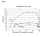
- FIG. 4 is a Tx diagram for the liquid-liquid equilibrium line for three systems composed of 1,3-propanediol + [bmim][PF 6 ], 1,3-propanediol + [bmim][BF 4 ], and 1,3-propanediol + [emim][BF 4 ] each plotted on the same figure.
- the Tx data for the solubility results are summarized in Examples 2-4.
- each trend line separates the region wherein the 1,3-propanediol and ionic liquid form one liquid phase from the region wherein the 1,3-propanediol and ionic liquid form two liquid phases.
- at temperatures inside the two-phase region i.e.
- the lower phase of the two-phase mixture is the ionic liquid-rich phase and the upper phase of the two-phase mixture is the 1,3-propanediol-rich phase.
- the upper critical solution temperature (UCST) for each composition is at the apex of each trend line. Depending on the composition, the UCST varied from 25°C to almost 85°C.
- a polyol such as 1,3,-propanediol (PDO)
- PDO 1,3,-propanediol
- An ionic liquid may be chosen such that, at the temperature of use, the energy transfer composition formed from that ionic liquid and a polyol preferably remains in the 1-phase region above the equilibrium bounday, and more preferably is above the UCST.
Landscapes
- Engineering & Computer Science (AREA)
- Chemical & Material Sciences (AREA)
- Thermal Sciences (AREA)
- Physics & Mathematics (AREA)
- Materials Engineering (AREA)
- Combustion & Propulsion (AREA)
- Chemical Kinetics & Catalysis (AREA)
- Organic Chemistry (AREA)
- Mechanical Engineering (AREA)
- General Engineering & Computer Science (AREA)
- Organic Low-Molecular-Weight Compounds And Preparation Thereof (AREA)
- Sorption Type Refrigeration Machines (AREA)
- Polyurethanes Or Polyureas (AREA)
Description
- This invention relates to thermal energy transfer systems wherein a mixture containing an ionic liquid is used as a thermal energy transfer composition.
- As a new type of solvent with immeasurable vapor pressure, roomtemperature ionic liquids are being studied for diverse applications, such as chemical separations and as unique reaction media. Several processes utilizing ionic liquids have been commercialized, such as the BASIL™ acid scavenging technology from BASF (Ludwigshafen, Germany).
- Thermal properties such as heat capacity, thermal conductivity, density, thermal stability, vapor pressure, and melting points have been measured for several ionic liquids (see, for example, Van Valkenburg et al, "Thermochemistry of Ionic Liquid Heat-Transfer Fluids", Thermochimica Acta, 2005, 181-188). One disadvantage of ionic liquids, however, is that the viscosity of most of them is relatively high, which reduces the opportunity to use them as thermal energy transfer fluids.
- A need thus remains for systems and methods by which ionic liquids may be used for thermal energy transfer purposes.
WO 2005/113702 andWO 2006/124776 disclose combinations of ionic liquids with working fluids; however, we have found that mixtures of polyols, such as 1,3-propanediol, with ionic liquids are suitable for use as thermal energy transfer compositions. - This invention relates to a thermal energy transfer composition that includes an ionic liquid and a polyol, and to methods and apparatus for thermal energy transfer that employ such composition.
- In one embodiment, the thermal energy transfer composition may be a mixture including 1,3-propanediol as the polyol and at least one ionic liquid. In another embodiment, the thermal energy transfer composition may be a mixture that may include 1,3-propanediol as the polyol and at least one ionic liquid, wherein the ionic liquid comprises a cation selected from the group consisting of pyridinium, pyridazinium, pyrimidinium, pyrazinium, imidazolium, pyrazolium, thiazolium, oxazolium and triazolium as described herein. The thermal energy transfer composition can act as a primary coolant or secondary coolant. In addition to a polyol, the thermal energy transfer composition may include additional coolants, or additives such as corrosion inhibitors and lubricants.
- A further embodiment of this invention includes an apparatus for thermal energy transfer that includes a thermal energy transfer composition that includes in admixture a polyol and at least one ionic liquid.
- In another embodiment, this invention provides a thermal energy transfer apparatus that includes a first chamber into and out of which flows a fluid, and a second chamber into and out of which flows a thermal energy transfer composition, wherein each chamber has one or more walls, the fluid and the thermal energy transfer composition are separated by a wall of one of the chambers or a wall that is common to both chambers, the respective temperatures of the fluid and the thermal energy transfer composition are not equal, and the thermal energy transfer composition comprises a polyol and an ionic liquid.
- In a further embodiment, this invention provides a method of transferring thermal energy by contacting a solid object, a fluid, or a chamber that contains the fluid with a thermal energy transfer composition, wherein the solid object or fluid has a first temperature, the thermal energy transfer composition has a second temperature, the first and second temperatures are not equal, and the thermal energy transfer composition comprises a polyol and an ionic liquid.
- In the embodiments described above, a suitable polyol for use therein is 1,3-propane diol.
- Yet another embodiment of this invention provides an apparatus for temperature adjustment that includes (a) an absorber that forms a mixture of a refrigerant and an absorbent; (b) a generator that receives the mixture from the absorber and heats the mixture to separate refrigerant, in vapor form, from the absorbent, and increases the pressure of the refrigerant vapor; (c) a condenser that receives the vapor from the generator and condenses the vapor under pressure to a liquid; (d) a pressure reduction device through which the liquid refrigerant leaving the condenser passes to reduce the pressure of the liquid to form a mixture of liquid and vapor refrigerant; (e) an evaporator that receives the mixture of liquid and vapor refrigerant that passes through the pressure reduction device to evaporate the remaining liquid to form refrigerant vapor; and (f) a conduit that passes the refrigerant vapor leaving the evaporator back to the absorber.
- Such an apparatus may be used for heating by locating the condenser in proximity to an object, medium or space to be heated, or the apparatus may be used for cooling by locating the evaporator in proximity to an object, medium or space to be cooled.
- In a further embodiment, this invention provides a process for adjusting the temperature of an object, medium or a space by (a) absorbing refrigerant vapor with an absorbent to form a mixture; (b) heating the mixture to separate refrigerant, in vapor form, from the absorbent and increase the pressure of the refrigerant vapor; (c) condensing the refrigerant vapor under pressure to a liquid; (d) reducing the pressure of the liquid refrigerant, and evaporating the refrigerant to form refrigerant vapor; and (e) repeating step (a) to re-absorb, with the absorbent, the refrigerant vapor.
- In the embodiment of the above described process, the temperature adjustment performed by the process may be an increase in temperature, and for that purpose refrigerant vapor is condensed to a liquid in proximity to an object, medium or space to be heated; or the temperature adjustment performed by the process may be a decrease in temperature, and for that purpose liquid refrigerant is evaporated in proximity to an object, medium or space to be cooled.
- In the embodiments such as described above, a polyol, such as 1,3-propane diol, may be used as the refrigerant, and an ionic liquid may be used as the absorbent.
-
-
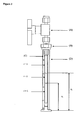
Figure 1 contains a schematic diagram of (a) the components of an apparatus or device for the performance of a simple absorption refrigeration cycle, and (b) the process steps in such cycle. -
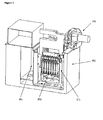
Figure 2 contains a schematic diagram of the testing apparatus used in the examples to determine vapor/liquid equilibrium ("VLE") or vapor/liquid/liquid equilibrium ("VLLE"), in which: i =1, lower liquid phase; i = 2, upper liquid phase, i = 3, vapor phase; h 1, height of lower liquid phase; h 2 height of upper liquid phase; (A) is Swagelok® valve, (B) is Swagelok® compression fitting; (C) is Teflon® fluoropolymer o-ring; and (D) outer tube is polycarbonate shield, inner tube is borosilicate glass. -
Figure 3 contains a schematic diagram of a sample holder and mixing apparatus used in the examples to determine VLE or VLLE for a group of samples; the apparatus is in upright position in constant temperature bath, and (A) is motor drive for rocking motion; (B) is constant temperature bath; (C) is rocking sample tube holder; (D) is sample tubes; (E) is viewing window. -
Figure 4 shows temperature-composition phase diagrams for 1,3-propanediol + [bmim][PF6]; 1,3-propanediol + [bmim][BF4]; and 1,3-propanediol + [emim][BF4]. Lines: trend lines. Diamonds: VLLE measurements for 1,3-propanediol + [bmim][PF6]; Squares: VLLE measurements for 1,3-propanediol + [emim][BF4]; Triangles: VLLE measurements for [bmim][BF4]. - This invention relates to a thermal energy transfer composition that includes an ionic liquid and a polyol, and to methods and apparatus for thermal energy transfer that employ such composition.
- In the description of this invention, the following definitional structure is provided for certain terminology as employed in various locations in the specification:
- "Alkane" refers to a saturated hydrocarbon having the general formula CnH2n+2, which may be a straight-chain, branched or cyclic. A cyclic compound requires a minimum of three carbons.
- "Alkene" refers to an unsaturated hydrocarbon that contains one or more C=C double bonds and that may be a straight-chain, branched or cyclic. An alkene requires a minimum of two carbons. A cyclic compound requires a minimum of three carbons.
- "Aromatic" refers to benzene and compounds that resemble benzene in chemical behavior.
- "Fluorinated ionic liquid" is defined as an ionic liquid having at least one fluorine on either the cation or the anion. A "fluorinated cation" or "fluorinated anion" is a cation or anion, respectively, comprising at least one fluorine.
- "Heteroaryl" refers to an alkyl group having a heteroatom.
- A "heteroatom" is an atom other than carbon in the structure of an alkanyl, alkenyl, cyclic or aromatic compound.
- An "ionic liquid" is defined as an organic salt that is fluid at or below about 100 °C.
- A "refrigerant" is a fluidic substance such as a polyol (e.g. 1,3-propanediol) that may be used as a thermal energy transfer vehicle. A refrigerant, when it changes phase from liquid to vapor (evaporates), removes heat from the surroundings; and when it changes phase from vapor to liquid (condenses), adds heat to the surroundings. Although the term refrigerant may carry the connotation of a substance used only for cooling, the term is used herein in the generic sense of a thermal energy transfer vehicle or substance that is applicable for use in a system or apparatus that may be used for heating or cooling.
- "Refrigerant pair", "refrigerant/absorbent pair" and "refrigerant/ionic liquid pair" are used interchangeably, and refer to a mixture suitable for use in the operation of an absorption cycle, which requires the presence of both a refrigerant and an absorbent, where the absorbent absorbs the refrigerant. As noted elsewhere, the absorbent herein may be an ionic liquid. A "refrigerant pair composition" is a composition comprising a refrigerant pair, a refrigerant/absorbent pair, or a refrigerant/ionic liquid pair.
- "Vacuum" refers to pressures less than about 1 bar but greater than about 10-4 bar for practical use in absorption cycles.
- This invention provides a system for thermal energy transfer that utilizes as a thermal energy transfer composition a composition that includes a polyol and at least one ionic liquid. A thermal energy transfer system provides a device, apparatus and/or equipment that facilitates the transfer of thermal energy between one object, medium and/or space that has a first temperature and another that has a second, different temperature. A thermal energy transfer system may thus be used either for heating or for cooling.
- Thermal energy may be transferred in a thermal energy transfer system, for example, by conductive and/or convective processes. In an industrial application using a heat exchanger, for example, two fluids at different temperatures are placed in contact with a conductive barrier (such as a tube wall) between them, and thermal energy is transferred from the fluid with the higher temperature through the conductive barrier to the fluid with the lower temperature until they reach the same temperature level.
- The driving force for thermal energy transfer is the difference in temperature between one object, medium or space and another, and the greater the difference in temperature the higher the rate at which the thermal energy will flow between them. Another factor of importance is the size of area over which one object, medium or space is enabled to contact another, or a common barrier between them, and the greater the size of the area the larger the amount of thermal energy that will flow in a given time with a given temperature difference. Yet another factor affecting thermal energy flow is the rate at which thermal energy will flow into or out from each object, medium or space. A high resistance to thermal energy flow in either object, medium or space will produce a slow overall rate of transfer. Yet another factor that will affect thermal energy flow is the rate at which thermal energy tends to flow through whatever conductive barrier (such as a metal tube or plate) as may exist between one object, medium and space and another, as influenced by the selection of material from which that conductive barrier is made.
- Representative forms that a thermal energy transfer system in this invention may take include a tube-and-shell heat exchanger and a plate heat exchanger. In a tube-and-shell heat exchanger, as the name implies, one or more tubes is installed within a cylindrical canister, and a fluid at one temperature flows into and out from the tube and another fluid at a second temperature flows into and out of the canister and in doing so surrounds the tube(s). One chamber may thus be installed within another. Thermal energy flows across the conductive barrier represented by the tube casing from the higher temperature fluid to the lower, and the thermal energy composition will adjust the temperature of the other fluid (the "other fluid"). Either the fluid in the canister or the fluid in the tube may be a thermal energy transfer composition according to this invention.
- Where a thermal energy transfer composition flows into and out from a tube such as in a tube-and-shell heat exchanger, resistance to thermal energy flow through the wall of the tube may be reduced by generating turbulence in the tube such as by incorporating therein saddles, twisted wires, tube deformations or other static mixers to disrupt the boundary layer of the flowing composition.
- In a plate heat exchanger, plates are arranged in such a way that there are formed channels of hot and cold liquid alternately, wherein the channels are adjacent to each other. Due to corrugations in the plate, high turbulent flow increases the thermal energy transfer rate. The plate produces an extremely large surface area, which allows for the fastest possible thermal energy transfer. Making each chamber thin ensures that the majority of the volume of the liquid contacts the plate, again aiding thermal energy exchange. A thermal energy transfer composition according to this invention may be used in either channel.
- Both types of heat exchangers as described above thus have chambers into and out from which a fluid flows - the tube, the shell and the channels, respectively; and each chamber has one or more walls that form the enclosure thereof. Whether flowing in the tube, the canister or one of the channels, the target fluid and the thermal energy transfer composition are separated by a wall of one of the chambers, e.g. the wall of a tube, or a wall that is common to both chambers, e.g. the wall between adjacent channels. The direction of flow of the target fluid may be parallel to, opposite to or across the direction of flow of the thermal energy transfer composition.
- Other aspects of thermal energy transfer systems and thermal energy transfer theory useful herein are described in "Heat Transfer" in Kirk-Othmer Encyclopedia of Chemical Technology, 5th Edition [Volume 13, pages 242-281 (2005) John Wiley & Sons, Inc., Hoboken, NJ] and Shah, R.K. and Mueller, A.C.; and "Heat Exchange" in Ullmann's Encyclopedia of Industrial Chemistry, Sixth Edition (pages 167-280, Wiley-VCH Verlag GmbH & CoA, Weinheim, Germany).
- This invention also provides a method for thermal energy transfer or for temperature adjustment, either cooling or heating, using a mixture that includes a polyol and at least one ionic liquid as a thermal energy transfer composition. A thermal energy transfer composition is used to transfer thermal energy between one object, medium and/or space that has a first temperature and another that has a second, different temperature. Such a method involves contacting a solid object, a target fluid, or a chamber that contains the target fluid with a thermal energy transfer composition, wherein the solid object or target fluid has a first temperature, the thermal energy transfer composition has a second temperature, the first and second temperatures are not equal, and the thermal energy transfer composition comprises a polyol and an ionic liquid. Where the thermal energy transfer composition is, for example, located in the tube of a tube-and-shell heat exchanger, the annulus of the canister formed by the exterior wall of the canister and the wall of the tube within the canister may be regarded as a chamber that contains the target fluid, and the thermal energy transfer composition contacts that chamber as it passes through the tube. Conversely, the target fluid may be in the tube and the thermal energy transfer composition may be in the shell.
- In the embodiments described above, either the fluid or the thermal energy transfer composition hereof may have the higher or lower temperature. The fluid may be a liquid or a gas, and when it is a gas, it may be contacted with the thermal energy transfer composition hereof by being bubbled through it. 1,3-Propane diol is a preferred polyol for use in the thermal energy transfer composition.
- An ionic liquid suitable for use herein is an ionic liquid with which, at least to some extent, a polyol is miscible, or in which, at least to some extent, a polyol is soluble. The energy efficiency of thermal energy transfer will increase in direct proportion to the extent to which the polyol is miscible with or soluble in at least one ionic liquid.
- The choice of ionic liquid will affect the freezing point of the thermal energy transfer composition. 1-Butyl-3-methylimidazolium hexafluorophosphate has a freezing point at 10°C, whereas 1-ethyl-3-methyl bis(trifluoromethylsulfonyl)imide has a freezing point at -20°C. Alternatively, an ionic liquid having a freezing point less than -20°C could be selected. In any event, the choice of ionic liquid can lead to freezing point depression of the thermal energy transfer composition. The freezing point for 1,3-propanediol, for example, is -27°C. When 1,3-propane diol is used as the poyol, if an ionic liquid is chosen that has a freezing point below -27°C, the freezing point of the composition will likely be lowered relative to that of the 1,3-propanediol alone. Other ionic liquids or combinations thereof, when mixed with 1,3-propanediol, will also result in a lowering of the freezing point beyond that of either the ionic liquid or 1,3-propanediol alone. Acetates, formates and succinates, for example, are known to reduce the freezing point of thermal energy transfer fluids, and ionic liquids having acetates, formates or succinates as or in the anion will thus also be suitable candidates to reduce the freezing point of thermal energy transfer fluids including mixtures comprising polyols such as 1,3-propanediol. Freezing points of ionic liquids can be found in the literature, or can be readily measured using melting point determinations.
- It is preferred in general that a thermal energy transfer composition formed from an ionic liquid and a polyol, such as 1,3-propane diol, have a single liquid phase, and not be present as two or more liquid phases. In a more specific embodiment, it is preferred that the composition be at a temperature that is, for that composition, outside of the liquid-liquid equilibrium boundary line between the 1-phase and the 2-phase systems. The liquid-liquid equilibrium boundary is the temperature at which, for a composition having a particular relative content of ionic liquid and polyol, the composition changes from 1 liquid phase to 2 liquid phases as temperature is decreasing, or from 2 liquid phases to 1 liquid phase as temperature is increasing. This boundary may be represented as a line on a chart that plots temperature on the Y axis and compositional content on the X axis. An example of three such boundary lines may be seen in
Figure 4 . For a composition having a selected content of its components, when the composition is at a temperature outside the boundary, or above the boundary line on the chart, the composition will have only a single liquid phase, and at a temperature inside the boundary, or below the boundary line on the chart, the composition will have two liquid phases. In the 2-phase region, the lower phase will be the ionic liquid-rich phase and the upper phase will be the 1,3-propanediol-rich phase. In a more specific embodiment, a thermal energy transfer composition, for a selected compositional content, may be at a temperature that is higher than the upper critical solution temperature (UCST), which is the temperature at the apex of the boundary line as shown on the chart. InFigure 4 , for example, the UCST for the bmimPF6 composition is at about 84°C. The UCST is the temperature above which a mixture is miscible. - A further embodiment of the use of a composition as provided by this invention for thermal energy transfer purposes involves the use of a mixture of a polyol and an ionic liquid as a refrigerant pair in an absorption cooling or heating cycle. There is thus further provided herein an absorption cooling or heating system that utilizes a refrigerant pair comprising a polyol as a refrigerant and at least one ionic liquid as an absorbent. This invention also provides a process for temperature adjustment, either cooling or heating, utilizing a mixture of a polyol as the refrigerant and at least one ionic liquid as the absorbent in an absorption cooling or heating system.
- A schematic diagram for a simple absorption cycle, and the apparatus by which it is run, is shown in
Figure 1 . The system is composed of condenser and evaporator units with an expansion valve similar to an ordinary vapor compression cycle, but an absorber-generator solution circuit replaces the compressor. The circuit may be composed of an absorber, a generator, a heat exchanger, a pressure control device and a pump for circulating the solution. In some embodiments, the thermal energy released by the absorber upon the absorption of the refrigerant by the absorbent may be used to heat a mixture of refrigerant and absorbent in the generator to separate the refrigerant in vapor form from the absorbent. - As shown in
Figure 1 , a typical apparatus for operating an absorption cycle may include components such as an absorber-generator solution circuit as shown on the left side of the drawing, which by the outflow and inflow of thermal energy increases the pressure of refrigerant vapor as a compressor does mechanically, where the circuit may be composed of an absorber, a generator, a heat exchanger, a pressure control device and a pump for circulating the solution. The apparatus also is composed of condenser and evaporator units with an expansion valve, as shown on the right side of the drawing. - In the apparatus as shown in
Figure 1 , mixture of a refrigerant and an absorbent is formed in the absorber; the mixture is passed to a generator where the mixture is heated to separate refrigerant, in vapor form, from the absorbent, and the pressure of the refrigerant vapor is increased; the refrigerant vapor is passed to a condenser where the vapor is condensed under pressure to a liquid; the liquid refrigerant is passed to an expansion device where the pressure of the liquid refrigerant is reduced to form a mixture of liquid and vapor refrigerant; the mixture of liquid and vapor refrigerant is passed to an evaporator where the remaining liquid is evaporated to form refrigerant vapor; the refrigerant vapor leaving the evaporator is passed to the absorber to repeat step (a) and re-form a mixture of the refrigerant vapor and the absorbent. - An apparatus as shown in
Figure 1 , and the apparatus as disclosed herein is capable of executing an absorption cycle using a polyol as the refrigerant and any one or more ionic liquids as described herein as the absorbent. The apparatus hereof is also capable of executing any one or more of the processes as described herein. Yet another embodiment of this invention is an apparatus substantially as shown or described inFigure 1 . - The absorber side of the absorption cycle will consist primarily of the ionic liquid. In one embodiment, the concentration of ionic liquid on the absorber side is greater than about 50% by weight of that of the ionic liquid plus the polyol. In an alternative embodiment, the concentration of ionic liquid on the absorber side is greater than about 70% by weight of that of the ionic liquid plus the polyol. The generator side of the absorption cycle will consist primarily of the polyol, with the concentration of the polyol being as high as 99 weight percent or greater relative to the weight of the ionic liquid plus the polyol.
- This invention also provides an apparatus for heating an object, medium or space that includes (a) an absorber that forms a mixture of a refrigerant and an absorbent; (b) a generator that receives the mixture from the absorber and heats the mixture to separate refrigerant, in vapor form, from the absorbent, and increases the pressure of the refrigerant vapor; (c) a condenser, located in proximity to the object, medium or space to be heated, that receives the vapor from the generator and condenses the vapor under pressure to a liquid; (d) a pressure reduction device through which the liquid refrigerant leaving the condenser passes to reduce the pressure of the liquid to form a mixture of liquid and vapor refrigerant; (e) an evaporator that receives the mixture of liquid and vapor refrigerant that passes through the pressure reduction device to evaporate the remaining liquid to form refrigerant vapor; and (f) a conduit that passes the refrigerant vapor leaving the evaporator to the absorber.
- This invention also provides an apparatus for cooling an object, medium or space that includes (a) an absorber that forms a mixture of a refrigerant and an absorbent; (b) a generator that receives the mixture from the absorber and heats the mixture to separate refrigerant, in vapor form, from the absorbent, and increases the pressure of the refrigerant vapor; (c) a condenser that receives the vapor from the generator and condenses the vapor under pressure to a liquid; (d) a pressure reduction device through which the liquid refrigerant leaving the condenser passes to reduce the pressure of the liquid to form a mixture of liquid and vapor refrigerant; (e) an evaporator, located in proximity to the object, medium or space to be cooled, that receives the mixture of liquid and vapor refrigerant that passes through the pressure reduction device to evaporate the remaining liquid to form refrigerant vapor; and (f) a conduit that passes the refrigerant vapor leaving the evaporator to the absorber.
- This invention also provides a process for heating an object, medium or a space comprising (a) absorbing refrigerant vapor with an absorbent to form a mixture; (b) heating the mixture to separate refrigerant, in vapor form, from the absorbent and increase the pressure of the refrigerant vapor; (c) condensing the refrigerant vapor under pressure to a liquid in proximity to the object, medium or space to be heated; (d) reducing the pressure of the liquid refrigerant, and evaporating the refrigerant to form refrigerant vapor; and (e) repeating step (a) to re-absorb, with the absorbent, the refrigerant vapor.
- This invention also provides a process for cooling an object, medium or a space comprising (a) absorbing refrigerant vapor with an absorbent to form a mixture; (b) heating the mixture to separate refrigerant, in vapor form, from the absorbent and increase the pressure of the refrigerant vapor; (c) condensing the refrigerant vapor under pressure to a liquid; (d) reducing the pressure of the liquid refrigerant, and evaporating the refrigerant, in proximity to the object, medium or space to be cooled, to form refrigerant vapor; and (e) repeating step (a) to re-absorb, with the absorbent, the refrigerant vapor.
- This invention also provides a process for heating an object, medium or a space in an apparatus that executes an absorption cycle by (a) forming in an absorber a mixture of a refrigerant and an absorbent; (b) passing the mixture to a generator where the mixture is heated to separate refrigerant, in vapor form, from the absorbent, and the pressure of the refrigerant vapor is increased; (c) passing the refrigerant vapor to a condenser in proximity to the object, medium or space to be heated where the vapor is condensed under pressure to a liquid; (d) passing the liquid refrigerant to an expansion device where the pressure of the liquid refrigerant is reduced to form a mixture of liquid and vapor refrigerant; (e) passing the mixture of liquid and vapor refrigerant to an evaporator where the remaining liquid is evaporated to form refrigerant vapor; and (f) passing the refrigerant vapor leaving the evaporator to the absorber to repeat step (a) and re-form a mixture of the refrigerant vapor and the absorbent.
- This invention also provides a process for cooling an object, medium or a space in an apparatus that executes an absorption cycle by (a) forming in an absorber a mixture of a refrigerant and an absorbent; (b) passing the mixture to a generator where the mixture is heated to separate refrigerant, in vapor form, from the absorbent, and the pressure of the refrigerant vapor is increased; (c) passing the refrigerant vapor to a condenser where the vapor is condensed under pressure to a liquid; (d) passing the liquid refrigerant to an expansion device where the pressure of the liquid refrigerant is reduced to form a mixture of liquid and vapor refrigerant; (e) passing the mixture of liquid and vapor refrigerant to an evaporator in proximity to the object, medium or space to be cooled where the remaining liquid is evaporated to form refrigerant vapor; and (f) passing the refrigerant vapor leaving the evaporator to the absorber to repeat step (a) and re-form a mixture of the refrigerant vapor and the absorbent.
- In any process as described above, the absorbent separated from refrigerant in step (b) may be recirculated for use in a later step.
- Mixtures of ionic liquids may also be used herein as the absorbent, and such mixtures may be desirable, for example, for achieving proper absorption behavior. 1,3-propane diol is a preferred polyol for use as the refrigerant in an absorption cycle.
- An absorption cycle, and systems in which they are run, are also described in Application Guide for Absorption Cooling/Refrigeration Using Recovered Heat [Dorgan et al (American Society of Heating, Refrigeration and Air Conditioning Engineers, Inc., 1995, Atlanta GA, Chapter 5)], and Haaf et al in "Refrigeration Technology" (Ullmann's Encyclopedia of Industrial Chemistry, Sixth Edition, Wiley-VCH Verlag GmbH, Weinheim, Germany, Volume 31, pages 269-312).
- When 1,3-propanediol, for example, is used as the polyol herein, it would in general be expected to be more miscible with or soluble in ionic liquids that are hydrophilic to some extent, and ionic liquids having cations having at least one alcohol side chain, or those comprising anions having at least one acetate or sulfate group, would thus be desirable choices for use in various embodiments of this invention. 1,3-Propanediol would in such case also preferably be miscible with or soluble in an ionic liquid as used herein over the temperature range of the operation of the absorption system, particularly from that of the evaporator to that of the generator. Evaporator temperatures can be as low as about 5°C. Single effect generator temperatures can be as high as about 150°C, while double effect generator temperatures can be as high as about 200°C. As a consequence, over a temperature range of from about 5°C to about 200°C, a variety of different levels of the relative content of the refrigerant and absorbent in an absorption cycle are suitable, and the concentration of either 1,3-propanediol or an ionic liquid in a composition formed therefrom may be in the range of from about 1% to about 99% by weight of the combined weight of the ionic liquid and 1,3-propanediol therein.
- A thermal energy transfer system as provided by this invention, such as a heat exchanger, may function, for example, as a condenser, heater, cooler or chiller. In such systems, a mixture of a polyol and an ionic liquid can be used as primary thermal energy transfer compositions (or primary coolants or refrigerants), wherein, for example, a body at one temperature is in contact with a second body at a higher temperature that is being cooled. Mixtures of a polyol and an ionic liquid can also be used as secondary thermal energy transfer compositions (or secondary coolants or refrigerants). Chilling is used to cool secondary thermal energy transfer compositions in order to remove thermal energy from other bodies. The use of secondary thermal energy transfer compositions is suitable when chilled fluid is to be distributed to several consumer locations or when contact between primary coolant and product resulting from leaks must be avoided. Examples of such systems include industrial air conditioning systems, food-cooling systems in grocery stores, and ice-skating rinks.
- As noted above, a thermal energy transfer system as provided by this invention may also operate to provide heating or cooling by employing an absorption refrigeration cycle (such as described in
US 2006/197,053 ), or by employing a hybrid vapor compression-absorption refrigeration cycle (such as described inUS 2007/019,708 ). - Any of the thermal energy transfer systems as described above may be deployed for use in, or fabricated or operated as, a refrigerator, a freezer, an ice machine, an air conditioner, an industrial cooling system, refrigeration system for cold room used for the preservation of foodstuffs of plant or animal origin, heater or heat pump. Each of these instruments may be situated in a residential, commercial or industrial setting, or may be incorporated into a mobilized device such as a car, truck, bus, train, airplane, or other device for transportation, or may be incorporated into a piece of equipment such as a medical instrument.
- In this invention, a thermal energy transfer composition is formed from one or more polyols and one or more ionic liquids. Ionic liquids are organic compounds that are liquid at room temperature (approximately 25°C). They differ from most salts in that they have very low melting points, and they tend to be liquid over a wide temperature range. Many of them are not soluble in non-polar hydrocarbons; are immiscible with water, depending on the anion; and many of them are highly ionizing (but have a low dielectric strength). Ionic liquids have essentially no vapor pressure, most are air and water stable, and they can either be neutral, acidic or basic.
- A cation or anion of an ionic liquid useful herein can in principle be any cation or anion such that the cation and anion together form an organic salt that is liquid at or below about 100°C. The properties of an ionic liquid can, however, be tailored by varying the identity of the cation and/or anion. For example, the acidity of an ionic liquid can be adjusted by varying the molar equivalents and type and combinations of Lewis acids used.
- Many ionic liquids are formed by reacting a nitrogen-containing heterocyclic ring, preferably a heteroaromatic ring, with an alkylating agent (for example, an alkyl halide) to form a quaternary ammonium salt, and performing ion exchange or other suitable reactions with various Lewis acids or their conjugate bases to form the ionic liquid. Examples of suitable heteroaromatic rings include substituted pyridines, imidazole, substituted imidazole, pyrrole and substituted pyrroles. These rings can be alkylated with virtually any straight, branched or cyclic C1-20 alkyl group, but preferably, the alkyl groups are C1-16 groups, since groups larger than this may produce low melting solids rather than ionic liquids. Various triarylphosphines, thioethers and cyclic and non-cyclic quaternary ammonium salts may also been used for this purpose. Counterions that may be used include chloroaluminate, bromoaluminate, gallium chloride, tetrafluoroborate, tetrachloroborate, hexafluorophosphate, nitrate, trifluoromethane sulfonate, methylsulfonate, p-toluenesulfonate, hexafluoroantimonate, hexafluoroarsenate, tetrachloroaluminate, tetrabromoaluminate, perchlorate, hydroxide anion, copper dichloride anion, iron trichloride anion, zinc trichloride anion, as well as various lanthanum, potassium, lithium, nickel, cobalt, manganese, and other metal-containing anions.
- Ionic liquids may also be synthesized by salt metathesis, by an acid-base neutralization reaction or by quaternizing a selected nitrogen-containing compound; or they may be obtained commercially from several companies such as Merck (Darmstadt, Germany) or BASF (Mount Olive, NJ).
- Representative examples of useful ionic liquids are described in sources such as J. Chem. Tech. Biotechnol., 68:351-356 (1997); Chem. Ind., 68:249-263 (1996); J. Phys. Condensed Matter, 5: (supp 34B):B99-B106 (1993); Chemical and Engineering News, Mar. 30, 1998, 32-37; J. Mater. Chem., 8:2627-2636 (1998); Chem. Rev., 99:2071-2084 (1999); and
US 2004/0133058 . In one embodiment hereof, a library, i.e. a combinatorial library, of ionic liquids may be prepared, for example, by preparing various alkyl derivatives of the quaternary ammonium cation, and varying the associated anions. - In one embodiment of this invention, ionic liquids suitable for use herein include those having cations represented by one or more of the following formulae:


- (i) H;
- (ii) halogen;
- (iii) -CH3, -C2H5, or C3 to C25 straight-chain, branched or cyclic alkane or alkene, optionally substituted with at least one member selected from the group consisting of Cl, Br, F, I, OH, NH2 and SH;
- (iv) -CH3, -C2H5, or C3 to C25 straight-chain, branched or cyclic alkane or alkene comprising one to three heteroatoms selected from the group consisting of O, N, Si and S, and optionally substituted with at least one member selected from the group consisting of Cl, Br, F, I, OH, NH2 and SH;
- (v) C6 to C20 unsubstituted aryl, or C3 to C25 unsubstituted heteroaryl having one to three heteroatoms independently selected from the group consisting of O, N, Si and S; and
- (vi) C6 to C25 substituted aryl, or C3 to C25 substituted heteroaryl having one to three heteroatoms independently selected from the group consisting of O, N, Si and S; and wherein the substituted aryl or substituted heteroaryl has one to three substituents independently selected from the group consisting of:
- (1) -CH3, -C2H5, or C3 to C25 straight-chain, branched or cyclic alkane or alkene, optionally substituted with at least one member selected from the group consisting of Cl, Br, F I, OH, NH2 and SH,
- (2) OH,
- (3) NH2, and
- (4) SH;
- (vii) -CH3, -C2H5, or C3 to C25 straight-chain, branched or cyclic alkane or alkene, optionally substituted with at least one member selected from the group consisting of Cl, Br, F, I, OH, NH2 and SH;
- (viii) -CH3, -C2H5, or C3 to C25 straight-chain, branched or cyclic alkane or alkene comprising one to three heteroatoms selected from the group consisting of O, N, Si and S, and optionally substituted with at least one member selected from the group consisting of Cl, Br, F, I, OH, NH2 and SH;
- (ix) C6 to C25 unsubstituted aryl, or C3 to C25 unsubstituted heteroaryl having one to three heteroatoms independently selected from the group consisting of O, N, Si and S; and
- (x) C6 to C25 substituted aryl, or C3 to C25 substituted heteroaryl having one to three heteroatoms independently selected from the group consisting of O, N, Si and S; and wherein the substituted aryl or substituted heteroaryl has one to three substituents independently selected from the group consisting of:
- (1) -CH3, -C2H5, or C3 to C25 straight-chain, branched or cyclic alkane or alkene, optionally substituted with at least one member selected from the group consisting of Cl, Br, F, I, OH, NH2 and SH,
- (2) OH,
- (3) NH2,and
- (4) SH; and
- In another embodiment, ionic liquids useful for the invention comprise fluorinated cations wherein at least one member selected from R1, R2, R3, R4, R5, R6, R7, R8, R9 and R10 comprises F-.
- In another embodiment, ionic liquids useful for the invention comprise imidazolium, such as 1-ethyl-3-methylimidazolium and 1-butyl-3-methylimidazolium.
- In one embodiment, ionic liquids useful herein have anions selected from the group consisting of [CH3CO2]-, [HSO4]-, [CH3OSO3]-, [C2H5OSO3]-, [AlCl4]-, [CO3]2-, [HCO3]-, [NO2]-, [NO3]-, [SO4]2-, [PO4]3-, [HPO4]2-, [H2PO4]-, [HSO3]-, [CuCl2]-, Cl-, Br-, I-, SCN-; and any fluorinated anion. Fluorinated anions useful herein include [BF4]-, [PF6]-, [SbF6]-, [CF3SO3]-, [HCF2CF2SO3]-, [CF3HFCCF2SO3]-, [HCClFCF2SO3]-, [(CF3SO2)2N]-, [(CF3CF2SO2)2N]-, [(CF3SO2)3C]-, [CF3CO2]-, [CF3OCFHCF2SO3]-, [CF3CF2OCFHCF2SO3]-, [CF3CFHOCF2CF2SO3]-, [CF2HCF2OCF2CF2SO3]-, [CF2ICF2OCF2CF2SO3]-, [CF3CF2OCF2CF2SO3]-, [(CF2HCF2SO2)2N]-, [(CF3CFHCF2SO2)2N]-; and F-.
- In a more specific embodiment, ionic liquids suitable for use herein may have a cation selected from the group consisting of pyridinium, pyridazinium, pyrimidinium, pyrazinium, imidazolium, pyrazolium, thiazolium, oxazolium, triazolium, phosphonium, and ammonium as defined above; and an anion selected from the group consisting of [CH3CO2]-, [HSO4]-, [CH3OSO3]-, [C2H5OSO3]-, [AlCl4]-, [CO3]2-, [HCO3]-, [NO2]-, [NO3]-, [SO4]2-, [PO4]3-, [HPO4]2-, [H2PO4]-, [HSO3]-, [CuCl2]-, Cl-, Br-, I-, SCN-, and any fluorinated anion. In yet another embodiment, ionic liquids suitable for use herein may have a cation selected from the group consisting of pyridinium, pyridazinium, pyrimidinium, pyrazinium, imidazolium, pyrazolium, thiazolium, oxazolium, triazolium, phosphonium, and ammonium as defined above; and an anion selected from the group consisting of [BF4]-, [PF6]-, [SbF6]-, [CF3SO3]-, [HCF2CF2SO3]-, [CF3HFCCF2SO3]-, [HCClFCF2SO3]-, [(CF3SO2)2N]-, [(CF3CF2SO2)2N]-, [(CF3SO2)3C]-, [CF3CO2]-, [CF3OCFHCF2SO3]-, [CF3CF2OCFHCF2SO3]-, [CF3CFHOCF2CF2SO3]-, [CF2HCF2OCF2CF2SO3]-, [CF2ICF2OCF2CF2SO3]-, [CF3CF2OCF2CF2SO3]-, [(CF2HCF2SO2)2N]-, [(CF3CFHCF2SO2)N]-, and F-.
- In still another embodiment, ionic liquids suitable for use herein may have a cation selected from the group consisting of pyridinium, pyridazinium, pyrimidinium, pyrazinium, imidazolium, pyrazolium, thiazolium, oxazolium, triazolium, phosphonium, and ammonium as defined above, wherein at least one member selected from R1, R2, R3, R4, R5, R6, R7, R8, R9 and R10 comprises F-; and an anion selected from the group consisting of [CH3CO2]-, [HSO4]-, [CH3OSO3]-, [C2H5OSO3]-, [AlCl4]-, [CO3]2-, [HCO3]-, [NO2]-, [NO3]-, [SO4]2-, [PO4]3-, [HPO4]2-, [H2PO4]-, [HSO3]-, [CuCl2]-, Cl-, Br-, I-, SCN-, and any fluorinated anion. In still another embodiment, ionic liquids suitable for use herein may have a cation selected from the group consisting of pyridinium, pyridazinium, pyrimidinium, pyrazinium, imidazolium, pyrazolium, thiazolium, oxazolium, triazolium, phosphonium, and ammonium as defined above, wherein at least one member selected from R1, R2, R3, R4, R5, R6, R7, R8, R9 and R10 comprises F-; and an anion selected from the group consisting of [BF4]-, [PF6]-, [SbF6]-, [CF3SO3]-, [HCF2CF2SO3]-, [CF3HFCCF2SO3]-, [HCClFCF2SO3]-, [(CF3SO2)2N]-, [(CF3CF2SO2)2N]-, [(CF3SO2)3C]-, [CF3CO2]-, [CF3OCFHCF2SO3]-, [CF3CF2OCFHCF2SO3]-, [CF3CFHOCF2CF2SO3]-, [CF2HCF2OCF2CF2SO3]-, [CF2ICF2OCF2CF2SO3]-, [CF3CF2OCF2CF2SO3]-, [(CF2HCF2SO2)2N]-, [(CF3CFHCF2SO2)2N]-, and F-.
- In one embodiment, the ionic liquid comprises imidazolium as the cation and [BF4]- or [PF6]- as the anion. In a more specific embodiment, the ionic liquid comprises 1-ethyl-3-methylimidazolium or 1-butyl-3-methylimidazolium as the cation, and [BF4]- or [PF6]- as the anion.
- The thermal energy transfer compositions provided by this invention, being mixtures of one or more polyols and one or more ionic liquids, are well suited for use for thermal energy transfer purposes because of their low viscosity, low density, high specific heat, high thermal conductivity, and high latent heat. In addition to 1,3-propane diol, polyols that may be selected for use herein in admixture with an ionic liquid to form the thermal energy transfer composition include ethylene glycol, 1,2-propane diol, 1,2,3-propane triol, and Cn linear or cyclic alkanes, where n = 4 to 8 (e.g. butane, pentane, hexane, heptane and octane), that are substituted with m hydroxyl groups, where m = 2 to n. Various polyols suitable for use herein may be made by processes known in the art, or are available commercially from suppliers such as Alfa Aesar (Ward Hill, Massachusetts), City Chemical (West Haven, Connecticut), Fisher Scientific (Fairlawn, New Jersey), Sigma-Aldrich (St. Louis, Missouri) or Stanford Materials (Aliso Viejo, California).
- 1,3-Propanediol suitable for use herein is available commercially. 1,3-Propanediol can be produced via a "hydroformylation route" by contacting ethylene oxide over a catalyst in the presence of phosphine, water, carbon monoxide, hydrogen and an acid. Alternatively, biologically-produced 1,3-propanediol (currently available from DuPont as Bio-PDO™ propane diol) can be provided for this invention by fermentation. Biologically-produced 1,3-propanediol is obtained by fermenting sugars, optionally obtained from renewable resources such as cellulosic biomass, to 1,3-propanediol. Such fermentation processes are know from and described in sources such as
U.S. Patents 5,686,276 and7,135,309 andUS 2006/0286653 . - In addition to a polyol, the thermal energy transfer compositions useful for the invention can also comprise additional coolants, such as water, or water admixed with lithium bromide as is commonly used in absorption technology. Additives, such as lubricants, corrosion inhibitors, stabilizers, dyes, and other appropriate materials may also be added to the thermal energy transfer mixtures useful for the invention for a variety of purposes provided they do not have an undesirable influence on the extent to which the polyol is soluble in an ionic liquid. The mixtures useful for the invention may be prepared by any convenient method, including mixing or combining the desired amounts of each component in an appropriate container using, for example, known types of stirrers having rotating mixing elements.
- In various embodiments of this invention, an ionic liquid formed by selecting any of the individual cations described or disclosed herein, and by selecting any of the individual anions described or disclosed herein with which to pair the cation, may be used as an absorbent in an absorption heating or cooling cycle, or as a component in a thermal energy transfer composition. Correspondingly, in yet other embodiments, a subgroup of ionic liquids formed by selecting (i) a subgroup of any size of cations, taken from the total group of cations described and disclosed herein in all the various different combinations of the individual members of that total group, and (ii) a subgroup of any size of anions, taken from the total group of anions described and disclosed herein in all the various different combinations of the individual members of that total group, may be used as an absorbent, or as a component in a thermal energy transfer composition. In forming an ionic liquid, or a subgroup of ionic liquids, by making selections as aforesaid, the ionic liquid or subgroup will be used in the absence of the members of the group of cations and/or anions that are omitted from the total group thereof to make the selection, and, if desirable, the selection may thus be made in terms of the members of the total group that are omitted from use rather than the members of the group that are included for use.
- In one embodiment of this invention, such as the absorption refrigeration cycle, the operation of a composition of a polyol and an ionic liquid as a thermal energy transfer composition, and in particular the operation of a polyol as a refrigerant and an ionic liquid as an absorbent, may be described in terms of thermodynamic property charts such as temperature-pressure-concentration (TPX) and enthalpy-temperature (HT) diagrams. These charts correspond to the familiar PH (pressure-enthalpy) or TS (temperature-entropy) diagram in analysis of the conventional vapor compression cycle. However; the use of these charts is adapted to the particular case of an absorption cycle since vapor compression uses a compressor, where the compression process is theoretically a single isentropic path, while the absorption cycle employs the so-called generator-absorber solution circuit, and several thermodynamic processes are involved.
- The PH or TS diagram in the vapor compression cycle is constructed using equations of state (EOS), and the cycle performance and all thermodynamic properties can be calculated. The thermodynamic charts for the absorption cycle are usually made by empirical correlation equations, which are fitted to experimental solubility and heat capacity data for solution properties, while the vapor phase properties are calculated with the refrigerant EOS. The solubility data may in certain instances be correlated using theoretical solution (often called "activity") models (Nezu et al, "Thermodynamic Properties of Working-Fluid Pairs with R-134a for Absorption Refrigeration System", Natural Working Fluids 2002, IIR Gustav Lorentzen Conf. 5th. China, (Sept. 17-20, 2002, 446-453); Fatouh, M. and Murthy, S. S. [Renewable Energy, 1993, 3:31-37]; Bhatt, M. S., et al [Heat Recovery System & CHP, 1992, 12:225-233]; Ness, H. C. V. and Abbott, M. M. [Classical Thermodynamics of Nonelectrolyte Solutions with Applications to Phase Equilibria, 1982, McGraw-Hill, New York]). However, such models may be limited in their use to temperatures well below the refrigerant critical temperature, and modeling solutions at high generator temperatures may become invalid. The combined use of empirical fitting equations or partially correct equations with the gas phase EOS may thus not always be completely consistent, and it is desirable to model the absorption cycle process with thermodynamically sound EOS. By the use of EOS, even above the critical temperature of refrigerants, thermodynamic properties can be correctly calculated.
- Although modeling refrigerant mixtures with EOS is familiar, refrigerant and non-volatile compound mixtures are traditionally treated with empirical correlation models by air conditioning and refrigeration engineers: e.g., refrigerant-lubricant oil solubility. Although one of the difficult problems in using EOS for such mixtures is determining how to set up EOS parameters for non-volatile compounds without much information about the critical parameters and vapor pressure data, EOS models have been successfully applied to refrigerant lubricant oil solubility data as more fully described in Yokozeki, A. [ Proc. Intl. Compressor Eng. Conf. at Purdue, 1994, 1:335-340]; Yokozeki, A. [Intl. J. Thermophys., 2001, 22:1057-1071]; and Yokozeki, A. [Applied Energy, 2005, 80:383-399]. Similar EOS models can therefore be used herein to calculate all thermodynamic properties consistently for use as an indicator of the utility of the refrigerants and ionic liquids disclosed herein as new absorption cycle fluid pairs (Tillner-Roth R and Friend DG [J. Phys. Chem. Ref. Data, 1998, 27, 63-96]).
- To model a refrigerant/ionic liquid composition, a generic Redlich-Kwong (RK) type of cubic equation of state (EOS) may be employed as follows:


The temperature-dependent part of the a parameter in the EOS for pure compounds is modeled by the following empirical form (Yokozeki, A. [Intl. J. Thermophys., 2001, 22:1057-1071]; Yokozeki, A. [Applied Energy, 2005, 80:383-399]; Shiflett, M. B. and Yokozeki, A. [Ind. Eng. Chem. Res. 2005, 44:4453-4464]):
The coefficients, β k , are determined so as to reproduce the vapor pressure of each pure compound. - For absorbents, however, vapor pressure data are usually not available, or vapor pressures are practically zero at application temperatures, and furthermore, no data for the critical parameters (Tc and Pc ) exist. The critical parameters of absorbents can, nevertheless, be estimated in various ways (Reid RC, et al., The Properties of Gases & Liquids, 4th edn. [McGraw-Hill, New York 1987]). As discussed by Yokozeki (Int. J. Thermophys., 2001, 22, 1057-1071), estimates of critical parameters for high boiling-point compounds are sufficient for correlating solubility (PTx) data. The temperature-dependent part of the a parameter for absorbents is significant however when the PTx data of refrigerant-absorbent mixtures are correlated, although the vapor pressure of absorbents is essentially zero at the temperature of interest. Here, α(T) for an absorbent is modeled by only two terms in
eq 4, as applied for the case of refrigerant-lubricant oil mixtures (Yokozeki A, 2001, supra).

The coefficient β 1 ineq 6 will be treated as an adjustable fitting parameter. - Then, the a and b parameters for general N-component mixtures are modeled in terms of binary interaction parameters (Yokozeki A [Applied Energy, 2005, 80, 383-399]; and Shiflett MB and Yokozeki A, supra), which may be regarded as a modified van der Waals-Berthelot mixing formula.


- Tci : critical temperature of i-th species.
- Pci : critical pressure of i-th species.
- xi : mole fraction of i-th species.
- For phase equilibrium (solubility) calculations, the fugacity coefficient φi for each compound is needed and derived for the present mixing rule:

where b'i and a'i are given by:

- A thermodynamically derived function relevant to the present study is an enthalpy (H), which is given, in a general form, by:

where C is an arbitrary constant, which can be any value of choice but must be the same constant for any component mixtures within the system in question. The ideal-gas heat capacity for each compoundin eq 13 is modeled with a polynomial form:

- Theoretical cycle performances for the absorption heating or cooling cycle as shown in
Figure 1 are modeled as follows. The overall energy balance gives:
From the material balance in the absorber or generator:
this provides a mass-flow-rate ratio, f, as defined by:
where x is a mass fraction of an absorbent in solution, the subscripts a and g stand for the absorber and generator solutions, and mr and ms are mass flow rates of gaseous refrigerant and absorber-exit solution (or solution pumping rate), respectively. - When a heat transfer efficiency of unity in the heat exchanger unit is assumed, the energy balance equation becomes:

where H is an enthalpy, and the subscript numbers (1, 2, 3, and 4) correspond to the locations shown inFigure 1 . From eq 18, the generator-inlet enthalpy, H 1, can be obtained:
From the energy balance around the generator, the generator heat input, Qg, is given by,
By eliminating H 1 from this equation with eq 19, eq 20 can be written as:
Similarly, the heat rejection in the absorber, Qa, is given by,
Condenser and evaporator heats per unit mass flow, respectively, are:

Then, the system performance is defined by a heat ratio, η, (output power divided by input power):
However, the solution pumping power, Wp , is usually much smaller than Q g, and it is customary to use a COP (coefficient of performance) defined as:
This can be expressed in terms of H and f:
Enthalpies at all locations and solubility in the absorber and generator units are calculated in a thermodynamically consistent way by use of the EOS model discussed above. - The pure component EOS constants for refrigerants have been taken from Yokozeki A (2001, supra), Yokozeki A (Proc. Int. Congress of Refrigeration, Washington, D.C. 2003), and EcoLibrium™ (2004, 3, 20-24). As for selected absorbents in this study, the critical parameters have been estimated from group contribution methods (Reid RC et al, supra). The accuracy in critical parameters for these high boiling-point materials is less important for correlating solubility data (Yokozeki A, 2001, supra). However, as mentioned earlier, the β 1 parameter in
eq 6 can be important, and will be treated as an adjustable parameter in the analysis of binary solubility data. - In order to calculate thermal properties with EOS, the ideal gas heat capacity for each pure compound is needed as a function of temperature: see eq 14. The coefficients for eq 14 have all been estimated from group contribution methods (Reid, RC, et al, supra).
- Next, the solubility (vapor-liquid equilibrium) data of fluorocarbon/ionic liquid binary mixtures is analyzed in order to determine the EOS parameters for mixtures. The four binary interaction parameters, lij , lji, mij, and τij , and the absorbent β 1 parameter for each binary pair have been determined by non-linear least squares analyses with an object function of relative pressure differences.
- Evaluation of the theoretical performance of an absorption heating or cooling cycle is based on a simple ideal cycle shown in
Figure 1 , and the present theoretical model. Here, the pumping power Wp is neglected, since it is usually insignificant with respect to other thermal powers. In addition, several assumptions are made: - (1) There is no pressure drop in connecting lines.
- (2) The refrigerant expansion process from the condenser to the evaporator is iso-enthalpic, as is usually done in vapor compression cycle calculations. The condition at
Point 7 inFigure 1 (exit of evaporator) is a pure refrigerant dew point with T = Teva. - (3) The condition at
Point 6 is a refrigerant bubble point, and there is no subcooled liquid. The condition at Point 5 (inlet to condenser) is a superheated state of a pure refrigerant with P = Pcon and T = Tg. - (4) Pressures in the condenser and the generator (Pcon and Pg) are the same, and evaporator and absorber pressures (Peva and Pa ) are similarly equal.
- (5) The condition at Point 3 (solution inlet to the absorber) is a solution's bubble point specified with the absorber pressure (Pa) and a solution concentration of the generator (xg ).
- (6) Temperatures in the generator (Tg ), absorber (Ta ), condenser (Tcon ), and evaporator (Teva ) are specified as a given cycle condition.
- (7) The refrigerant gas flow rate (mr ) is set to be 1 kg· s-1, without loss of generality, and the absorbent vapor is neglected.
- The first step of cycle calculations is to obtain Peva and Pcon as saturated vapor pressures of a pure refrigerant at given temperatures: Bubble-Point P routine (Ness, HCV et al, supra). Then, using a usual TP (Temperature-Pressure) Flash routine (Ness, HCV et al, supra), absorbent compositions, xg and xa, in the generator and absorber units are calculated. This provides f (flow rate ratio) in eq 17. The thermodynamic properties at
Point 3 are determined from the assumption (5): Bubble-Point T routine (Ness, HCV et al, supra). The enthalpy atPoint 1 is obtained from eq 19. Enthalpies at all other points are easily calculated with known T, P and compositions. Thus, the necessary quantities for the performance evaluation can be obtained using the listed equations. Cycle performances for the present binary systems are summarized in Example 1, Table 1 with selected thermodynamic quantities, where the specified temperatures for the cycle condition are: Tg / Tcon / Ta /Teva = 100 / 40 / 30 /10°C, and mr = 1 kg·s-1. - The well-known refrigerant-absorbent pairs, NH3/H2O and H2O/LiBr, have also been calculated and are shown in Example 1, Table 1 for comparison. In the case of NH3/H2O, the absorbent H2O has a non-negligible vapor pressure at the generator exit, and in practical applications a rectifier (distillation) unit is required in order to separate the refrigerant from absorbent water. The effect of vapor pressure and extra power requirement due to the rectifier have been ignored; thus, the calculated COP is over-estimated for the present performance comparison. For H2O/LiBr, the EOS model was not developed. Instead, empirical correlation diagrams for the thermodynamic properties were employed (temperature-pressure-concentration diagram and enthalpy-temperature diagram in Stoecker and Jones, Refrigeration and Air Conditioning [McGraw-Hill, New York, 1982, 328-350]).
- Cycle calculations for an absorption refrigeration cycle may be readily made using the EOS as described herein, but analysis of the results benefits from a different approach than used in the case of an ordinary vapor compression cycle. In the latter case, a high pressure/temperature refrigerant gas is produced by a vapor compressor, where the thermodynamic process is theoretically a single isentropic step: inlet and exit enthalpies of the compressor are sufficient for describing the compressor work. In the absorption cycle, however, the process of generating the corresponding high pressure/temperature gas is more complicated, and it is useful to know enthalpies at several different locations as well as refrigerant-absorbent solubility differences at the absorber and generator units (related to the f value), as seen in eqs. 17, 21 and 22.
- The condenser and evaporator performance is the same for both cycles at given temperatures, and may be understood based on the latent heat of vaporization (or condensation). In general, the refrigerating effect is the latent heat at the evaporator, which increases with an increase in the temperature difference between Tc and Teva. Thus, at a given. Teva , the latent heat is larger for a refrigerant with a higher Tc. In addition, the molar latent heat (J/mol) is generally not so much different among refrigerants at their boiling point (or far away from Tc ), while the specific latent heat (J/kg) can be significantly different due to a large difference in molar masses. These factors can explain large differences in the calculated refrigerating power Qe.
- An absorbent as used in an absorption heating or cooling cycle is desirably a compound that has high solubility for a refrigerant (e.g. 1,3-propanediol) and also a very high boiling point relative to the refrigerant. Example 1, Table 1 exemplifies the system of 1,3-propanediol + [bmim][BF4], which has COP/f values of 0.40/22.6.
- The following examples are presented to illustrate the advantages of the present invention and to assist one of ordinary skill in making and using the same. They illustrate the particular situation where 1,3-propane diol has been selected as the polyol. These examples are not intended in any way, however, to limit the scope of the disclosure and the appended claims.
- The following abbreviations are used: MPa is mega Pascal; kPA is kilo Pascal; K is Kelvin, °C is degrees Centigrade; mm is millimeter; cm is centimeter; kW is kilowatt; PDO is 1,3-propanediol; and mol is mole.
- 1-Butyl-3-methylimidazolium hexafluorophosphate ([bmim][PF6], C8H15N2F6P, molecular weight 284.18 g mol-1), 1-butyl-3-methylimidazolium tetrafluoroborate ([bmim][BF4], C8H15N2F4B, molecular weight 226.13 g mol-1), 1-ethyl-3-methylimidazolium tetrafluoroborate ([emim][BF4], C6H11N2F4B, molecular weight 197.98 g mol-1), were obtained from Fluka Chemika (may be obtained from Sigma-Aldrich, St. Louis, Missouri) with a purity of >97%. 1,3-propanediol (C3H8O2, molecular weight 76.1 g mol-1) and methyl alcohol were obtained from Sigma-Aldrich with a minimum purity of 99.6 %.
- The syntheses of the following anions are described in
U.S. 2007/0131535 : (potassium 1,1,2,2-tetrafluoroethanesulfonate, potassium-1,1,2-trifluoro-2-(perfluoroethoxy)ethanesulfonate, potassium-1,1,2-trifluoro-2-(trifluoromethoxy)ethanesulfonate, and sodium 1,1,2,3,3,3-hexafluoropropanesulfonate) and ionic liquids (1-butyl-2,3-dimethylimidazolium 1,1,2,2-tetrafluoroethanesulfonate, 1-butyl-methylimidazolium 1,1,2,2-tetrafluoroethanesulfonate, 1-ethyl-3-methylimidazolium 1,1,2,2-tetrafluoroethane sulfonate, 1-ethyl-3-methylimidazolium 1,1,2,3,3,3-hexafluoropropanesulfonate, 1-hexyl-3-methylimidazolium 1,1,2,2-tetrafluoroethanesulfonate, 1-dodecyl-3-methylimidazolium 1,1,2,2-tetrafluoroethanesulfonate, -hexadecyl-3-methylimidazolium 1,1,2,2-tetrafluoroethanesulfonate, 1-octadecyl-3-methylimidazolium 1,1,2,2-tetrafluoroethaneulfonate, 1-propyl-3-(1,1,2,2-TFES) imidazolium 1,1,2,2-tetrafluoroethanesulfonate, 1-butyl-3-methylimidazolium 1,1,2,3,3,3-hexafluoropropanesulfonate, 1-butyl-3-methylimidazolium 1,1,2-trifluoro-2-(trifluoromethoxy)ethanesulfonate, 1-butyl-3-methylimidazolium 1,1,2-trifluoro-2-(perfluoroethoxy)ethanesulfonate, tetradecyl(tri-n-butyl)phosphonium 1,1,2,3,3,3-hexafluoropropanesulfonate, tetradecyl(tri-n-hexyl)phosphonium 1,1,2-trifluoro-2-(perfluoroethoxy)ethanesulfonate, tetradecyl(tri-n-hexyl)phosphonium 1,1,2-trifluoro-2-(trifluoromethoxy)ethanesulfonate, 1-ethyl-3-methylimidazolium 1,1,2,2-tetrafluoro-2-(pentafluoroethoxy)sulfonate, and tetrabutylphosphonium 1,1,2-trifluoro-2-(perfluoroethoxy)ethanesulfonate). - For a composition of a polyol, such as 1,3-propanediol, and an ionic liquid to be useful as a thermal energy transfer composition, the polyol should be soluble in the ionic liquid at least to some extent. The thermal energy transfer composition will also preferably remain single phase, and not separate into two liquid phases, at the temperature of use. In order to measure the vapor-liquid-liquid equilibria ("VLLE") for mixtures of 1,3-propanediol with various ionic liquids, low-pressure sample containers were fabricated from borosilicate glass tubing with an outside diameter of 12.69 mm, an inside diameter of 7.94 mm, and an overall length of 15.5 cm. The glass tubing was sealed with a torch on one end and open on the other. A Swagelok® stainless steel (Swagelok Co., Solon, OH; SS316) cap and plug with Teflon® polymer ferrules was used to seal the open end of the glass tubing. When tightening the cap, the ferrules must seal against the glass tubing, but care must be taken so that over-tightening does not crack the glass.
- The volume of each liquid layer was obtained by measuring the liquid height from the bottom of the glass tubing as illustrated in
Figure 2 using an electronic caliper (Mitutoyo America Corp., Aurora, IL; model no. CD-6" CS, code no. 500-196) with an accuracy of ±0.01 mm. The volume (v) versus the height (h) was calibrated experimentally, and an excellent linear relation, v = a + bh, was obtained. The a and b parameters were obtained for each tube using methyl alcohol as a reference sample at 293.15 K. - When a binary system exhibits a liquid-liquid separation (or VLLE), it is a univariant state according to the Gibbs phase rule; the thermodynamic freedom is one. For example, if a system temperature T is fixed, then all other thermodynamic intensive variables (pressure, compositions and molar volumes in each phase) are uniquely determined, regardless of any given overall-feed compositions. The overall feed composition only changes the physical volume in each liquid phase and gas phase, but the composition and molar volume in each phase remain constant as long as the three phases exist at the fixed T.
- This unique VLLE state of a binary system can be determined experimentally using a simple apparatus, shown schematically in
Figure 2 , by mass-and-volume measurements alone without using any analytical method for analysis of the composition. The principle of the present method is based on the thermodynamic constraint, the univariant state (Gibbs phase rule), and the mass balance, as described in Shiflett, M.B. and Yokozeki, A. (Vapor-liquid-liquid equilibria of pentafluoroethane and ionic liquid [bmim][PF6] mixtures studied with the volumetric method, J. Phys. Chem. B (2006) 110:14436-14443) and Shiflett, M.B. and Yokozeki, A. (Vapor-liquid-liquid equilibria of hydrofluorocarbons + 1-butyl-3-methylimidazolium hexafluorophosphate, J. Chem. & Eng. Data (2006) 51:1931-1939). - To establish the thermodynamic equilibrium, sufficient time and mixing were required. A custom-made mixing apparatus, which can hold 14 sample containers, was designed for rocking the tubes back and forth in a constant temperature bath (Tamson Instruments b.v., Zoetermeer, The Netherlands; model no. TV4000LT) with a viewing window as shown in
Figure 3 . The bath was filled with Dow Coming silicon oil (Dow Coming, Midland, MI; model no. 5010) with a recommended use range of (233.15 < T < 403.15) K. The bath had excellent temperature control with a uniformity of ±0.02 K. Before height measurements were taken, the sample holder was positioned upright below the liquid level of the tank for 6 to 12 h. The mixing and measurement procedure was repeated each day and the heights plotted as a function of time until no further change in the heights was detected. Using this procedure required 5 days to reach equilibrium at each temperature. -
Figure 4 is a Tx diagram for the liquid-liquid equilibrium line for three systems composed of 1,3-propanediol + [bmim][PF6], 1,3-propanediol + [bmim][BF4], and 1,3-propanediol + [emim][BF4] each plotted on the same figure. The Tx data for the solubility results are summarized in Examples 2-4. InFigure 4 , each trend line separates the region wherein the 1,3-propanediol and ionic liquid form one liquid phase from the region wherein the 1,3-propanediol and ionic liquid form two liquid phases. For a particular composition, at temperatures inside the two-phase region (i.e. below the trend line on the diagram), the lower phase of the two-phase mixture is the ionic liquid-rich phase and the upper phase of the two-phase mixture is the 1,3-propanediol-rich phase. The upper critical solution temperature (UCST) for each composition is at the apex of each trend line. Depending on the composition, the UCST varied from 25°C to almost 85°C. - If a polyol; such as 1,3,-propanediol (PDO), is mixed with an ionic liquid for use as a thermal energy transfer composition, avoiding the formation of two liquid phases is preferred. An ionic liquid may be chosen such that, at the temperature of use, the energy transfer composition formed from that ionic liquid and a polyol preferably remains in the 1-phase region above the equilibrium bounday, and more preferably is above the UCST.
- For the systems tested, it was found, for example, that the following compositions: compositions less than 10 mol% PDO in [bmim][PF6]; compositions greater than 99.5 mol% PDO in [bmim][PF6]; compositions less than 35 mol% PDO in [bmim][BF4]; compositions greater than 96 mol% PDO in [bmim][BF4]; compositions less than 23 mol% PDO in [emim][BF4]; and compositions greater than 98 mol% PDO in [emim][BF4] all had the desirable property that they remained single phase at temperatures as low as 10°C; these
-
Table 1. Comparisons of Theoretical Cycle Performances.(a) PDO; 1,3-propanediol Binary Systems (1)/(2) Pcon, Pg kPa Peva, Pa kPa f xg Mass % xa mass % Qe kW COP PDO/[bmim][BF4] 0.0211 0.0013 22.6 98.5 94.1 1212 0.400 NH3/H2O 1548 615 2.54 59.5 36.1 1112 0.646 H2O/LiBr 7.38 1.23 4.08 66.3 50.0 2502 0.833 (a)Cycle conditions: Tg / Tcon / Ta / Teva = 100 / 40 / 30 /10 °C, and mr = 1 kg·s-1. - Experimental solubility (Tx) data for 1,3-propanediol in 1-butyl-3-methylimidazolium hexafluorophosphate ([bmim][PF6]) are summarized in Table 2.
Table 2. 1,3-Propanediol (1) + [bmim][PF6] (2) system T/K mol% PDO lower phase mol% PDO upper phase 286.6 ± 0.2 10.9 ± 1.7 99.4 ± 0.1 287.8 ± 0.2 11.4 ± 2.3 99.4 ± 0.1 288.2 ± 0.2 11.8 ± 1.6 99.4 ± 0.1 291.9 ± 0.2 13.3±1.9 99.1 ± 0.1 298.3 ± 0.2 15.0 ± 2.4 99.0 ± 0.1 303.3 ± 0.2 15.5 ± 1.5 98.8 ± 0.1 313.5 ± 0.2 19.0 ± 1.9 98.5 ± 0.1 323.4 ± 0.2 24.3±1.5 97.8 ± 0.1 - Experimental solubility (Tx) data for 1,3-propanediol in 1-butyl-3-methylimidazolium tetrafluoroborate ([bmim][BF4]) are summarized in Table 3.
Table 3. 1,3-Propanediol (1) + [bmim][BF4] (2) system T/K mol% PDO lower phase mol% PDO upper phase 286.7 ± 0.2 36.8 ± 0.2 95.8 ± 0.8 287.9 ± 0.2 38.4 ± 0.4 95.2 ± 0.2 289.1 ± 0.2 39.7 ± 0.4 94.9 ± 0.2 291.9 ± 0.2 47.0 ± 0.5 93.1 ± 0.1 - Experimental solubility (Tx) data for 1,3-propanediol in 1-ethyl-3-methylimidazolium tetrafluoroborate ([emim][BF4]) are summarized in Table 4.
Table 4. 1,3-Propanediol (1) + [emim][BF4] (2) system T/K mol% PDO lower phase mol% PDO upper phase 286.6 ± 0.2 23.8 ± 0.5 97.0 ± 0.2 287.8 ± 0.2 24.5 ± 0.5 97.0 ± 0.2 288.2 ± 0.2 24.9 ± 0.4 96.8 ± 0.2 291.9 ± 0.2 30.9 ± 0.4 95.8 ± 0.2 298.3 ± 0.2 35.8 ± 0.4 94.5 ± 0.2 303.3 ± 0.2 43.5 ± 0.3 92.2 ± 0.1 - In this specification, unless explicitly stated otherwise or indicated to the contrary by the context of usage, where an embodiment of the subject matter hereof is stated or described as comprising, including, containing, having, being composed of or being constituted by or of certain features or elements, one or more features or elements in addition to those explicitly stated or described may be present in the embodiment. An alternative embodiment of the subject matter hereof, however, may be stated or described as consisting essentially of certain features or elements, in which embodiment features or elements that would materially alter the principle of operation or the distinguishing characteristics of the embodiment are not present therein. A further alternative embodiment of the subject matter hereof may be stated or described as consisting of certain features or elements, in which embodiment, or in insubstantial variations thereof, only the features or elements specifically stated or described are present.
- In this specification, unless explicitly stated otherwise or indicated to the contrary by the context of usage,
- (a) use of the indefinite article "a" or "an" with respect to a statement or description of the presence of an element or feature of this invention, does not limit the presence of the element or feature to one in number; and
- (b) the words "include", "includes" and "including" are to be read and interpreted as if they were followed by the phrase "without limitation" if in fact that is not the case.
Claims (14)
- An apparatus for thermal energy transfer comprising a thermal energy transfer composition that comprises in admixture a polyol and at least one ionic liquid.
- An apparatus according to Claim 1 wherein the composition has a single liquid phase.
- An apparatus according to Claim 1 wherein the polyol comprises 1,3-propane diol.
- An apparatus according to Claim 1 that comprises a first chamber into and out of which flows a fluid, and a second chamber into and out of which flows the thermal energy transfer composition, wherein each chamber has one or more walls, the fluid and the thermal energy transfer composition are separated by a wall of one of the chambers or a wall that is common to both chambers, and the respective temperatures of the fluid and the thermal energy transfer composition are not equal.
- An apparatus according to Claim 4 wherein one of the chambers is located within the other, or the chambers are adjacent to each other.
- An apparatus according to Claim 4 wherein the direction of flow of the fluid is parallel to, opposite to or across the direction of flow of the composition.
- An apparatus for temperature adjustment comprising (a) an absorber that forms a mixture of a refrigerant and an absorbent; (b) a generator that receives the mixture from the absorber and heats the mixture to separate refrigerant, in vapor form, from the absorbent, and increases the pressure of the refrigerant vapor; (c) a condenser that receives the vapor from the generator and condenses the vapor under pressure to a liquid; (d) a pressure reduction device through which the liquid refrigerant leaving the condenser passes to reduce the pressure of the liquid to form a mixture of liquid and vapor refrigerant; (e) an evaporator that receives the mixture of liquid and vapor refrigerant that passes through the pressure reduction device to evaporate the remaining liquid to form refrigerant vapor; and (f) a conduit that passes the refrigerant vapor leaving the evaporator back to the absorber; wherein the absorbent comprises an ionic liquid, and the refrigerant comprises a polyol.
- An apparatus according to Claim 7 wherein the polyol comprises 1,3-propane diol.
- An apparatus according to Claim 7 wherein the condenser is located in proximity to an object, medium or space to be heated, or the evaporator is located in proximity to an object, medium or space to be cooled.
- A method of transferring thermal energy comprising contacting a solid object, a fluid, or a chamber that contains the fluid with a thermal energy transfer composition, wherein the solid object or fluid has a first temperature, the thermal energy transfer composition has a second temperature, the first and second temperatures are not equal, and the thermal energy transfer composition comprises a polyol and an ionic liquid.
- A method according to Claim 10 wherein the fluid comprises a gas, and the gas is bubbled through the composition.
- A method according to Claim 10 wherein the first temperature is higher than the second, or the first temperature is lower than the second.
- A method according to Claim 10 comprising providing a flow of the fluid and a flow of the composition, wherein the direction of flow of the fluid is parallel to, opposite to or across the direction of flow of the composition.
- A method according to Claim 10 wherein the polyol comprises 1,3-propane diol, and the method further comprises a step of providing the 1,3-propane diol by fermentation.
Applications Claiming Priority (2)
| Application Number | Priority Date | Filing Date | Title |
|---|---|---|---|
| US92158507P | 2007-04-03 | 2007-04-03 | |
| PCT/US2008/004436 WO2008124087A1 (en) | 2007-04-03 | 2008-04-03 | Heat transfer systems using mixtures of polyols and ionic liquids |
Publications (2)
| Publication Number | Publication Date |
|---|---|
| EP2129737A1 EP2129737A1 (en) | 2009-12-09 |
| EP2129737B1 true EP2129737B1 (en) | 2012-10-17 |
Family
ID=39639042
Family Applications (1)
| Application Number | Title | Priority Date | Filing Date |
|---|---|---|---|
| EP08742585A Not-in-force EP2129737B1 (en) | 2007-04-03 | 2008-04-03 | Heat transfer systems using mixtures of polyols and ionic liquids |
Country Status (6)
| Country | Link |
|---|---|
| US (1) | US20100132384A1 (en) |
| EP (1) | EP2129737B1 (en) |
| JP (1) | JP5343068B2 (en) |
| KR (1) | KR20100016135A (en) |
| CN (1) | CN101657515B (en) |
| WO (1) | WO2008124087A1 (en) |
Families Citing this family (23)
| Publication number | Priority date | Publication date | Assignee | Title |
|---|---|---|---|---|
| US8463441B2 (en) | 2002-12-09 | 2013-06-11 | Hudson Technologies, Inc. | Method and apparatus for optimizing refrigeration systems |
| US8715521B2 (en) * | 2005-02-04 | 2014-05-06 | E I Du Pont De Nemours And Company | Absorption cycle utilizing ionic liquid as working fluid |
| EP2190488A1 (en) * | 2007-09-28 | 2010-06-02 | E. I. du Pont de Nemours and Company | Ionic liquid stabilizer compositions |
| AU2011235567B2 (en) * | 2010-04-01 | 2015-02-05 | Enermotion Inc. | A system and method for storing thermal energy as auxiliary power in a vehicle |
| DE102010022408B4 (en) * | 2010-06-01 | 2016-11-24 | Man Truck & Bus Ag | Method and apparatus for operating a steam cycle with lubricated expander |
| CA2802840A1 (en) * | 2010-06-17 | 2011-12-22 | Tomas Abyhammar | A method in treating solvent containing gas |
| CA2817264C (en) * | 2010-11-08 | 2016-12-13 | Evonik Degussa Gmbh | Working medium for absorption heat pumps |
| CN104080880B (en) * | 2012-02-02 | 2017-07-25 | 普罗伊奥尼克有限公司 | For the ionic liquid cooled down in hot environment |
| WO2013192162A1 (en) * | 2012-06-20 | 2013-12-27 | E. I. Du Pont De Nemours And Company | Low temperature heat transfer fluid and system |
| CA2798036C (en) * | 2012-12-05 | 2020-01-21 | Nova Chemicals Corporation | Reduction of fouling in high pressure reactors |
| CN103673374A (en) * | 2013-11-22 | 2014-03-26 | 清华大学 | Working medium pair suitable for absorbing type energy storage circulation |
| DE102014001499A1 (en) * | 2014-02-06 | 2015-08-06 | Api Schmidt-Bretten Gmbh & Co. Kg | For heat and / or mass transfer suitable plate apparatus |
| CN104046334A (en) * | 2014-06-23 | 2014-09-17 | 西安交通大学 | Functional group modified phase-change heat-storing ionic liquid |
| US10808970B2 (en) | 2015-09-28 | 2020-10-20 | University Of Florida Research Foundation, Incorporated | Ionic liquid-based absorption cooling system with high coefficient of performance |
| US10168080B2 (en) * | 2016-05-26 | 2019-01-01 | Yazaki Corporation | Eutectic mixtures of ionic liquids in absorption chillers |
| US10465950B2 (en) | 2016-05-26 | 2019-11-05 | Yazaki Corporation | Guanidinium-based ionic liquids in absorption chillers |
| CN106753271B (en) * | 2016-12-29 | 2019-11-15 | 山东省科学院能源研究所 | Organic refrigerating/heat-conducting medium and preparation method thereof |
| WO2018208308A1 (en) * | 2017-05-11 | 2018-11-15 | General Electric Company | Cooling systems and related method |
| CN107543332A (en) * | 2017-10-09 | 2018-01-05 | 广州市香港科大霍英东研究院 | A kind of close-coupled absorbing refrigeration system |
| US11796229B2 (en) | 2019-03-22 | 2023-10-24 | Solvcor Technologies. Llc | Systems and methods for high energy density heat transfer |
| MX2020007857A (en) * | 2018-01-26 | 2021-01-20 | Ethan J Novek | Systems and methods for active cloud point adjustment and refrigeration cycles. |
| EP3886854A4 (en) | 2018-11-30 | 2022-07-06 | Nuvation Bio Inc. | Pyrrole and pyrazole compounds and methods of use thereof |
| WO2020198100A1 (en) * | 2019-03-22 | 2020-10-01 | Novek Ethan J | Refrigeration cycle with liquid-liquid phase transitions |
Family Cites Families (25)
| Publication number | Priority date | Publication date | Assignee | Title |
|---|---|---|---|---|
| DE1642833A1 (en) * | 1967-03-16 | 1971-04-29 | Yves Henderyckx | Method and device for separating one or more components from a solution |
| NL7412102A (en) * | 1974-09-12 | 1976-03-16 | Lucius Hendrikus Dominicus Jos | Shell and tube heat exchanger - with static mixer elements mounted between tubes to improve shell side coefficient |
| JPS60125203A (en) * | 1983-12-13 | 1985-07-04 | Nitto Electric Ind Co Ltd | Thermo-pervaporation apparatus |
| JPS6112782A (en) * | 1985-05-17 | 1986-01-21 | Toray Ind Inc | Method for using absorption type heat pump |
| US5686276A (en) * | 1995-05-12 | 1997-11-11 | E. I. Du Pont De Nemours And Company | Bioconversion of a fermentable carbon source to 1,3-propanediol by a single microorganism |
| IL136407A0 (en) * | 1997-12-02 | 2001-06-14 | Du Pont | Method for the production of glycerol by recombinant organisms |
| US5894883A (en) * | 1998-03-25 | 1999-04-20 | Phillips Petroleum Company | Shell and tube heat exchanger |
| JP3553833B2 (en) * | 1998-10-12 | 2004-08-11 | 本田技研工業株式会社 | Absorption refrigerator |
| US7109241B1 (en) * | 2000-10-02 | 2006-09-19 | Ecolab, Inc. | Antimicrobial compositions formulated for use in cold temperature conditions and methods of use thereof |
| WO2002074718A2 (en) * | 2001-03-20 | 2002-09-26 | Basf Aktiengesellschaft | Ionic liquids as selective additives for the separation of close-boiling or azeotropic mixtures |
| DE10316418A1 (en) * | 2003-04-10 | 2004-10-21 | Basf Ag | Use an ionic liquid |
| JP4814794B2 (en) * | 2003-05-06 | 2011-11-16 | イー・アイ・デュポン・ドウ・ヌムール・アンド・カンパニー | Purification of biologically produced 1,3-propanediol |
| CN102876754A (en) * | 2004-01-16 | 2013-01-16 | 诺维信股份有限公司 | Methods for degrading lignocellulosic materials |
| DE102004024967A1 (en) * | 2004-05-21 | 2005-12-08 | Basf Ag | New absorption media for absorption heat pumps, absorption chillers and heat transformers |
| US20060139426A1 (en) * | 2004-12-28 | 2006-06-29 | Fuji Xerox Co., Ltd. | Ink, ink set, processing solution, recording method, recording medium, ink tank, and recording device |
| US7313926B2 (en) * | 2005-01-18 | 2008-01-01 | Rexorce Thermionics, Inc. | High efficiency absorption heat pump and methods of use |
| WO2006084285A2 (en) * | 2005-01-31 | 2006-08-10 | Exxonmobil Chemical Patents Inc. | Olefin oligomerization and biodegradable compositions therefrom |
| US8715521B2 (en) * | 2005-02-04 | 2014-05-06 | E I Du Pont De Nemours And Company | Absorption cycle utilizing ionic liquid as working fluid |
| US7765823B2 (en) * | 2005-05-18 | 2010-08-03 | E.I. Du Pont De Nemours And Company | Hybrid vapor compression-absorption cycle |
| JP4942069B2 (en) * | 2005-09-06 | 2012-05-30 | 日本カーリット株式会社 | Conductivity imparting agent and conductive material |
| AR058054A1 (en) * | 2005-09-22 | 2008-01-23 | Du Pont | USE OF IONIC LIQUIDS FOR THE SEPARATION OF HYDROFLUOROCARBURES |
| DE602006006861D1 (en) * | 2005-09-22 | 2009-06-25 | Du Pont | PREPARATION OF POLYTRIMETHYLENETHERGLYCOL AND COPOLYMERS THEREOF |
| US8506839B2 (en) * | 2005-12-14 | 2013-08-13 | E I Du Pont De Nemours And Company | Absorption cycle utilizing ionic liquids and water as working fluids |
| JP5371747B2 (en) * | 2006-05-31 | 2013-12-18 | イー・アイ・デュポン・ドウ・ヌムール・アンド・カンパニー | Vapor compression using ionic liquid as compressor lubricant |
| US20080153697A1 (en) * | 2006-12-22 | 2008-06-26 | E. I. Dupont De Nemours And Company | Mixtures of ammonia and ionic liquids |
-
2008
- 2008-04-03 JP JP2010502145A patent/JP5343068B2/en not_active Expired - Fee Related
- 2008-04-03 WO PCT/US2008/004436 patent/WO2008124087A1/en active Application Filing
- 2008-04-03 KR KR1020097022889A patent/KR20100016135A/en not_active Application Discontinuation
- 2008-04-03 US US12/594,247 patent/US20100132384A1/en not_active Abandoned
- 2008-04-03 CN CN200880011088XA patent/CN101657515B/en not_active Expired - Fee Related
- 2008-04-03 EP EP08742585A patent/EP2129737B1/en not_active Not-in-force
Also Published As
| Publication number | Publication date |
|---|---|
| WO2008124087A8 (en) | 2009-04-30 |
| CN101657515A (en) | 2010-02-24 |
| WO2008124087A1 (en) | 2008-10-16 |
| US20100132384A1 (en) | 2010-06-03 |
| EP2129737A1 (en) | 2009-12-09 |
| KR20100016135A (en) | 2010-02-12 |
| CN101657515B (en) | 2013-04-17 |
| JP2010523931A (en) | 2010-07-15 |
| JP5343068B2 (en) | 2013-11-13 |
Similar Documents
| Publication | Publication Date | Title |
|---|---|---|
| EP2129737B1 (en) | Heat transfer systems using mixtures of polyols and ionic liquids | |
| US8506839B2 (en) | Absorption cycle utilizing ionic liquids and water as working fluids | |
| US9039922B2 (en) | Low-temperature and average-temperature refrigeration | |
| US8069687B2 (en) | Working media for refrigeration processes | |
| EP2258787A2 (en) | Absorption cycle utilizing ionic liquid as working fluid | |
| CN100557343C (en) | Mixed vapour compression-absorption circulation | |
| US20140286849A1 (en) | Mixtures of Ammonia and Ionic Liquids | |
| Sabil et al. | Estimations of enthalpies of dissociation of simple and mixed carbon dioxide hydrates from phase equilibrium data | |
| Chen et al. | Investigation on vapor–liquid equilibria for binary systems of metal ion-containing ionic liquid [bmim] Zn2Cl5/NH3 by experiment and modified UNIFAC model | |
| WO2014193857A1 (en) | Refrigeration system with dual refrigerants and liquid working fluids | |
| Oliveira et al. | Flow boiling of hydrocarbons and their zeotropic binary mixtures under pre-and post-dryout conditions | |
| de Araújo et al. | Thermodynamic performance analysis of a single-effect absorption refrigeration system operating with water and 1-ethyl-3-methylimidazolium-based ionic liquids mixtures | |
| US4793940A (en) | Absorbent composition for refrigeration and heating systems | |
| Esaki et al. | Experimental absorption solubility and rate of hydrofluoroolefin refrigerant in ionic liquids for absorption chiller cycles | |
| Guo et al. | The performance of [Emim] Br/H2O as a working pair in the absorption refrigeration system | |
| MX2008007557A (en) | Absorption cycle utilizing ionic liquids and water as working fluids |
Legal Events
| Date | Code | Title | Description |
|---|---|---|---|
| PUAI | Public reference made under article 153(3) epc to a published international application that has entered the european phase |
Free format text: ORIGINAL CODE: 0009012 |
|
| 17P | Request for examination filed |
Effective date: 20090918 |
|
| AK | Designated contracting states |
Kind code of ref document: A1 Designated state(s): AT BE BG CH CY CZ DE DK EE ES FI FR GB GR HR HU IE IS IT LI LT LU LV MC MT NL NO PL PT RO SE SI SK TR |
|
| 17Q | First examination report despatched |
Effective date: 20100401 |
|
| DAX | Request for extension of the european patent (deleted) | ||
| GRAP | Despatch of communication of intention to grant a patent |
Free format text: ORIGINAL CODE: EPIDOSNIGR1 |
|
| RIC1 | Information provided on ipc code assigned before grant |
Ipc: C09K 5/04 20060101AFI20120402BHEP Ipc: F25B 15/02 20060101ALI20120402BHEP |
|
| GRAS | Grant fee paid |
Free format text: ORIGINAL CODE: EPIDOSNIGR3 |
|
| GRAA | (expected) grant |
Free format text: ORIGINAL CODE: 0009210 |
|
| AK | Designated contracting states |
Kind code of ref document: B1 Designated state(s): AT BE BG CH CY CZ DE DK EE ES FI FR GB GR HR HU IE IS IT LI LT LU LV MC MT NL NO PL PT RO SE SI SK TR |
|
| REG | Reference to a national code |
Ref country code: GB Ref legal event code: FG4D |
|
| REG | Reference to a national code |
Ref country code: CH Ref legal event code: EP |
|
| REG | Reference to a national code |
Ref country code: IE Ref legal event code: FG4D |
|
| REG | Reference to a national code |
Ref country code: AT Ref legal event code: REF Ref document number: 579919 Country of ref document: AT Kind code of ref document: T Effective date: 20121115 |
|
| REG | Reference to a national code |
Ref country code: DE Ref legal event code: R096 Ref document number: 602008019449 Country of ref document: DE Effective date: 20121213 |
|
| REG | Reference to a national code |
Ref country code: AT Ref legal event code: MK05 Ref document number: 579919 Country of ref document: AT Kind code of ref document: T Effective date: 20121017 |
|
| REG | Reference to a national code |
Ref country code: NL Ref legal event code: VDEP Effective date: 20121017 |
|
| REG | Reference to a national code |
Ref country code: LT Ref legal event code: MG4D |
|
| PG25 | Lapsed in a contracting state [announced via postgrant information from national office to epo] |
Ref country code: ES Free format text: LAPSE BECAUSE OF FAILURE TO SUBMIT A TRANSLATION OF THE DESCRIPTION OR TO PAY THE FEE WITHIN THE PRESCRIBED TIME-LIMIT Effective date: 20130128 Ref country code: IS Free format text: LAPSE BECAUSE OF FAILURE TO SUBMIT A TRANSLATION OF THE DESCRIPTION OR TO PAY THE FEE WITHIN THE PRESCRIBED TIME-LIMIT Effective date: 20130217 Ref country code: LT Free format text: LAPSE BECAUSE OF FAILURE TO SUBMIT A TRANSLATION OF THE DESCRIPTION OR TO PAY THE FEE WITHIN THE PRESCRIBED TIME-LIMIT Effective date: 20121017 Ref country code: SE Free format text: LAPSE BECAUSE OF FAILURE TO SUBMIT A TRANSLATION OF THE DESCRIPTION OR TO PAY THE FEE WITHIN THE PRESCRIBED TIME-LIMIT Effective date: 20121017 Ref country code: NL Free format text: LAPSE BECAUSE OF FAILURE TO SUBMIT A TRANSLATION OF THE DESCRIPTION OR TO PAY THE FEE WITHIN THE PRESCRIBED TIME-LIMIT Effective date: 20121017 Ref country code: HR Free format text: LAPSE BECAUSE OF FAILURE TO SUBMIT A TRANSLATION OF THE DESCRIPTION OR TO PAY THE FEE WITHIN THE PRESCRIBED TIME-LIMIT Effective date: 20121017 Ref country code: NO Free format text: LAPSE BECAUSE OF FAILURE TO SUBMIT A TRANSLATION OF THE DESCRIPTION OR TO PAY THE FEE WITHIN THE PRESCRIBED TIME-LIMIT Effective date: 20130117 Ref country code: FI Free format text: LAPSE BECAUSE OF FAILURE TO SUBMIT A TRANSLATION OF THE DESCRIPTION OR TO PAY THE FEE WITHIN THE PRESCRIBED TIME-LIMIT Effective date: 20121017 |
|
| PG25 | Lapsed in a contracting state [announced via postgrant information from national office to epo] |
Ref country code: GR Free format text: LAPSE BECAUSE OF FAILURE TO SUBMIT A TRANSLATION OF THE DESCRIPTION OR TO PAY THE FEE WITHIN THE PRESCRIBED TIME-LIMIT Effective date: 20130118 Ref country code: CY Free format text: LAPSE BECAUSE OF FAILURE TO SUBMIT A TRANSLATION OF THE DESCRIPTION OR TO PAY THE FEE WITHIN THE PRESCRIBED TIME-LIMIT Effective date: 20121017 Ref country code: SI Free format text: LAPSE BECAUSE OF FAILURE TO SUBMIT A TRANSLATION OF THE DESCRIPTION OR TO PAY THE FEE WITHIN THE PRESCRIBED TIME-LIMIT Effective date: 20121017 Ref country code: LV Free format text: LAPSE BECAUSE OF FAILURE TO SUBMIT A TRANSLATION OF THE DESCRIPTION OR TO PAY THE FEE WITHIN THE PRESCRIBED TIME-LIMIT Effective date: 20121017 Ref country code: PL Free format text: LAPSE BECAUSE OF FAILURE TO SUBMIT A TRANSLATION OF THE DESCRIPTION OR TO PAY THE FEE WITHIN THE PRESCRIBED TIME-LIMIT Effective date: 20121017 Ref country code: BE Free format text: LAPSE BECAUSE OF FAILURE TO SUBMIT A TRANSLATION OF THE DESCRIPTION OR TO PAY THE FEE WITHIN THE PRESCRIBED TIME-LIMIT Effective date: 20121017 Ref country code: PT Free format text: LAPSE BECAUSE OF FAILURE TO SUBMIT A TRANSLATION OF THE DESCRIPTION OR TO PAY THE FEE WITHIN THE PRESCRIBED TIME-LIMIT Effective date: 20130218 |
|
| PG25 | Lapsed in a contracting state [announced via postgrant information from national office to epo] |
Ref country code: AT Free format text: LAPSE BECAUSE OF FAILURE TO SUBMIT A TRANSLATION OF THE DESCRIPTION OR TO PAY THE FEE WITHIN THE PRESCRIBED TIME-LIMIT Effective date: 20121017 |
|
| PG25 | Lapsed in a contracting state [announced via postgrant information from national office to epo] |
Ref country code: BG Free format text: LAPSE BECAUSE OF FAILURE TO SUBMIT A TRANSLATION OF THE DESCRIPTION OR TO PAY THE FEE WITHIN THE PRESCRIBED TIME-LIMIT Effective date: 20130117 Ref country code: CZ Free format text: LAPSE BECAUSE OF FAILURE TO SUBMIT A TRANSLATION OF THE DESCRIPTION OR TO PAY THE FEE WITHIN THE PRESCRIBED TIME-LIMIT Effective date: 20121017 Ref country code: DK Free format text: LAPSE BECAUSE OF FAILURE TO SUBMIT A TRANSLATION OF THE DESCRIPTION OR TO PAY THE FEE WITHIN THE PRESCRIBED TIME-LIMIT Effective date: 20121017 Ref country code: SK Free format text: LAPSE BECAUSE OF FAILURE TO SUBMIT A TRANSLATION OF THE DESCRIPTION OR TO PAY THE FEE WITHIN THE PRESCRIBED TIME-LIMIT Effective date: 20121017 Ref country code: EE Free format text: LAPSE BECAUSE OF FAILURE TO SUBMIT A TRANSLATION OF THE DESCRIPTION OR TO PAY THE FEE WITHIN THE PRESCRIBED TIME-LIMIT Effective date: 20121017 |
|
| PGFP | Annual fee paid to national office [announced via postgrant information from national office to epo] |
Ref country code: GB Payment date: 20130403 Year of fee payment: 6 Ref country code: DE Payment date: 20130327 Year of fee payment: 6 |
|
| PLBE | No opposition filed within time limit |
Free format text: ORIGINAL CODE: 0009261 |
|
| STAA | Information on the status of an ep patent application or granted ep patent |
Free format text: STATUS: NO OPPOSITION FILED WITHIN TIME LIMIT |
|
| PG25 | Lapsed in a contracting state [announced via postgrant information from national office to epo] |
Ref country code: RO Free format text: LAPSE BECAUSE OF FAILURE TO SUBMIT A TRANSLATION OF THE DESCRIPTION OR TO PAY THE FEE WITHIN THE PRESCRIBED TIME-LIMIT Effective date: 20121017 Ref country code: IT Free format text: LAPSE BECAUSE OF FAILURE TO SUBMIT A TRANSLATION OF THE DESCRIPTION OR TO PAY THE FEE WITHIN THE PRESCRIBED TIME-LIMIT Effective date: 20121017 |
|
| 26N | No opposition filed |
Effective date: 20130718 |
|
| REG | Reference to a national code |
Ref country code: DE Ref legal event code: R097 Ref document number: 602008019449 Country of ref document: DE Effective date: 20130718 |
|
| PG25 | Lapsed in a contracting state [announced via postgrant information from national office to epo] |
Ref country code: MC Free format text: LAPSE BECAUSE OF FAILURE TO SUBMIT A TRANSLATION OF THE DESCRIPTION OR TO PAY THE FEE WITHIN THE PRESCRIBED TIME-LIMIT Effective date: 20121017 |
|
| REG | Reference to a national code |
Ref country code: CH Ref legal event code: PL |
|
| REG | Reference to a national code |
Ref country code: IE Ref legal event code: MM4A |
|
| PG25 | Lapsed in a contracting state [announced via postgrant information from national office to epo] |
Ref country code: LI Free format text: LAPSE BECAUSE OF NON-PAYMENT OF DUE FEES Effective date: 20130430 Ref country code: CH Free format text: LAPSE BECAUSE OF NON-PAYMENT OF DUE FEES Effective date: 20130430 |
|
| REG | Reference to a national code |
Ref country code: FR Ref legal event code: ST Effective date: 20131231 |
|
| PG25 | Lapsed in a contracting state [announced via postgrant information from national office to epo] |
Ref country code: FR Free format text: LAPSE BECAUSE OF NON-PAYMENT OF DUE FEES Effective date: 20130430 |
|
| PG25 | Lapsed in a contracting state [announced via postgrant information from national office to epo] |
Ref country code: IE Free format text: LAPSE BECAUSE OF NON-PAYMENT OF DUE FEES Effective date: 20130403 |
|
| REG | Reference to a national code |
Ref country code: DE Ref legal event code: R119 Ref document number: 602008019449 Country of ref document: DE |
|
| GBPC | Gb: european patent ceased through non-payment of renewal fee |
Effective date: 20140403 |
|
| PG25 | Lapsed in a contracting state [announced via postgrant information from national office to epo] |
Ref country code: DE Free format text: LAPSE BECAUSE OF NON-PAYMENT OF DUE FEES Effective date: 20141101 Ref country code: GB Free format text: LAPSE BECAUSE OF NON-PAYMENT OF DUE FEES Effective date: 20140403 |
|
| REG | Reference to a national code |
Ref country code: DE Ref legal event code: R119 Ref document number: 602008019449 Country of ref document: DE Effective date: 20141101 |
|
| PG25 | Lapsed in a contracting state [announced via postgrant information from national office to epo] |
Ref country code: MT Free format text: LAPSE BECAUSE OF FAILURE TO SUBMIT A TRANSLATION OF THE DESCRIPTION OR TO PAY THE FEE WITHIN THE PRESCRIBED TIME-LIMIT Effective date: 20121017 |
|
| PG25 | Lapsed in a contracting state [announced via postgrant information from national office to epo] |
Ref country code: TR Free format text: LAPSE BECAUSE OF FAILURE TO SUBMIT A TRANSLATION OF THE DESCRIPTION OR TO PAY THE FEE WITHIN THE PRESCRIBED TIME-LIMIT Effective date: 20121017 |
|
| PG25 | Lapsed in a contracting state [announced via postgrant information from national office to epo] |
Ref country code: LU Free format text: LAPSE BECAUSE OF NON-PAYMENT OF DUE FEES Effective date: 20130403 Ref country code: HU Free format text: LAPSE BECAUSE OF FAILURE TO SUBMIT A TRANSLATION OF THE DESCRIPTION OR TO PAY THE FEE WITHIN THE PRESCRIBED TIME-LIMIT; INVALID AB INITIO Effective date: 20080403 |