EP2129348B1 - Abgestufter mikrokeratom-schaufelhalter - Google Patents
Abgestufter mikrokeratom-schaufelhalter Download PDFInfo
- Publication number
- EP2129348B1 EP2129348B1 EP08744713.2A EP08744713A EP2129348B1 EP 2129348 B1 EP2129348 B1 EP 2129348B1 EP 08744713 A EP08744713 A EP 08744713A EP 2129348 B1 EP2129348 B1 EP 2129348B1
- Authority
- EP
- European Patent Office
- Prior art keywords
- drive
- pin
- blade holder
- blade
- top surface
- Prior art date
- Legal status (The legal status is an assumption and is not a legal conclusion. Google has not performed a legal analysis and makes no representation as to the accuracy of the status listed.)
- Not-in-force
Links
- 230000010355 oscillation Effects 0.000 claims description 4
- 230000000630 rising effect Effects 0.000 claims 3
- 210000004087 cornea Anatomy 0.000 description 7
- 238000001356 surgical procedure Methods 0.000 description 6
- 230000000712 assembly Effects 0.000 description 4
- 238000000429 assembly Methods 0.000 description 4
- 210000003128 head Anatomy 0.000 description 2
- 238000003780 insertion Methods 0.000 description 2
- 230000037431 insertion Effects 0.000 description 2
- 230000015572 biosynthetic process Effects 0.000 description 1
- 239000000919 ceramic Substances 0.000 description 1
- 239000000463 material Substances 0.000 description 1
- 230000013011 mating Effects 0.000 description 1
- 239000002184 metal Substances 0.000 description 1
- 238000000034 method Methods 0.000 description 1
- 239000004033 plastic Substances 0.000 description 1
Images


Classifications
-
- A—HUMAN NECESSITIES
- A61—MEDICAL OR VETERINARY SCIENCE; HYGIENE
- A61B—DIAGNOSIS; SURGERY; IDENTIFICATION
- A61B17/00—Surgical instruments, devices or methods
- A61B17/32—Surgical cutting instruments
- A61B17/326—Circumcision apparatus
-
- A—HUMAN NECESSITIES
- A61—MEDICAL OR VETERINARY SCIENCE; HYGIENE
- A61F—FILTERS IMPLANTABLE INTO BLOOD VESSELS; PROSTHESES; DEVICES PROVIDING PATENCY TO, OR PREVENTING COLLAPSING OF, TUBULAR STRUCTURES OF THE BODY, e.g. STENTS; ORTHOPAEDIC, NURSING OR CONTRACEPTIVE DEVICES; FOMENTATION; TREATMENT OR PROTECTION OF EYES OR EARS; BANDAGES, DRESSINGS OR ABSORBENT PADS; FIRST-AID KITS
- A61F9/00—Methods or devices for treatment of the eyes; Devices for putting in contact-lenses; Devices to correct squinting; Apparatus to guide the blind; Protective devices for the eyes, carried on the body or in the hand
- A61F9/007—Methods or devices for eye surgery
- A61F9/013—Instruments for compensation of ocular refraction ; Instruments for use in cornea removal, for reshaping or performing incisions in the cornea
Definitions
- the present invention is related to microkeratome blade holders and blade assemblies for use in microkeratomes. More specifically, the present invention is directed to a stepped blade holder for more easily assuring that a microkeratome blade assembly is properly loaded into a microkeratome before use during surgery.
- Microkeratomes and their associated blade assemblies and blade holders are well-known in the art.
- Microkeratomes include the HansatomeTM and the XP MicrokeratomeTM both, of which are sold by Bausch & Lomb Incorporated, the assignee of the present invention.
- U.S. Patent No. 6,051,009 entitled Automatic Surgical Device for Cutting a Cornea and a Cutting Blade Assembly and Control Assembly and U.S. Patent Publication No. 2004/0236358 entitled Bar-Link Drive System for a Microkeratome both describe microkeratomes and related microkeratome blade assemblies.
- Blade holders are typically a structure attached to a metal, ceramic, or plastic cutting blade.
- the blade holder and the attached cutting blade form a blade assembly that fits within mating structure of the microkeratome.
- the blade holder typically cooperates with an eccentric drive-pin via a drive slot formed in the blade holder.
- the drive-pin properly positioned within the drive slot, then oscillates the blade assembly during operation of the microkeratome, as it is passed across the cornea of a patient's eye during surgery, to form a corneal flap, such as for LASIK surgery.
- the oscillation of the blade during movement of the blade assembly across the cornea of a patient's eye is important in order to effectively and efficiently cut the cornea of the patient's eye; therefore, the seating or placement of the eccentric drive-pin in the drive slot of the blade holder is particularly important to ensure that the blade is oscillated.
- Prior art blade assemblies described in the above-referenced patents and in other known microkeratomes are effective in oscillating the blade assembly and safely and efficiently cutting a cornea during surgery, if the microkeratome blade assembly is properly placed within the microkeratome and the drive slot is properly engaged with the drive-pin of the microkeratome.
- the blade assembly may not be properly loaded into the microkeratome, and a user through inattention or some other mistake may not fully place the blade assembly within the microkeratome. This may prevent the drive-pin from being engaged with the drive slot of the blade holder. If this occurs, serious complications could result and an improper flap may be formed or other damage not intended could be done to a patient's cornea.
- U.S. patent 6,165,189 entitled Microkeratome for Performing LASIK Surgery discloses a conical counter sink in an upper surface of a sled. This counter sink may allow for easier engagement with an eccentric drive-pin but the sled must still be placed well into the microkeratome before the counter sink would be effective.
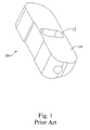
- FIG. 1 shows a perspective view of a prior art blade holder 10 having a drive slot 12 and an essentially top surface 14.
- the present invention improves on the prior art of FIG. 1 by forming a series of steps on a top surface. These steps cooperate with the rotation of a drive-pin to ensure that as the eccentric drive-pin of the microkeratome is rotated, the steps cooperate with the drive-pin to ensure that the drive-pin engages with the drive slot of a blade holder.
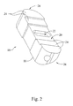
- FIG. 2 shows a perspective view of a blade holder 16 for attachment to a microkeratome blade, in accordance with the present invention.
- Blade holder 16 includes a bottom surface 18. Bottom surface 18 is shown at the line 18, but cannot be seen in the perspective view.
- a drive slot 22 is formed in top surface 20 and is for engagement with the drive-pin for allowing oscillation of blade holder 16.
- a plurality of steps 24 are formed in the top surface 20, and rise from the drive slot 22 toward at least one side, shown generally at 26, of the blade holder 16.
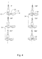
- a width of each step 24 is less than a diameter of rotation of the drive-pin for ensuring that the drive-pin is directed toward the drive slot 22.
- This relationship between the width of the step and the rotation of the drive-pin is shown more explicitly below with regard to FIG. 4 .
- the formation of the three steps 24 in blade holder 16 ensures that the drive-pin will be engaged in the drive slot 22 within three revolutions of the drive-pin after the drive-pin contacts the top surface 20.
- a plurality of steps should be formed toward at least one side of the blade holder; but depending on the design of the microkeratome, it may be desirable for the steps to be formed from the drive slot 22 toward opposing sides of the blade holder 16, as shown in FIG. 2 .
- Such a symmetrical step configuration as shown in FIG. 2 is particularly desirable in microkeratomes designed to allow for blade assembly insertion from either of opposing sides.
- Other microkeratomes may be designed to only allow blade assembly insertion from one side and therefore, it would only require steps to be formed on one side of the blade holder.
- more or fewer than the three steps formed from the drive slot toward the sides of blade holder 16 may be formed, depending on the diameter of rotation of the drive-pin to be used in conjunction with the blade assembly.
- FIG. 3 shows a microkeratome blade assembly 28 with a cutting blade 30 attached to blade holder 16. Bottom surface 18 is attached to the blade 30. Top surface 20 interfaces with a drive-pin of a microkeratome, as described in detail below. A drive slot 22 is formed in the top surface 20 for engagement with the drive-pin. As in FIG. 2 , a plurality of steps are formed in the top surface 20 and rise from the drive slot 22 towards opposing sides 26 of the blade holder 16.
- FIG. 4 shows a series of drawings depicting how the inventive blade holder 16 cooperates with an eccentric drive-pin 32, to ensure that drive-pin 32 is engaged in drive slot 22 within three revolutions.
- the series of drawings of FIG. 4 depict the drive-pin 32 and blade holder 16; though in operation those skilled in the art will appreciate, the drive-pin 32 is contained within the microkeratome and blade holder 16 is attached to a cutting blade 30, which has at least partially been loaded into a microkeratome. In the example used, blade holder 16 is only partially engaged within a microkeratome, such as shown in the drawing at 0°.
- eccentric pin 32 When eccentric pin 32 starts to rotate and reaches 180°, because pin 32 is typically spring loaded and the width of steps 24 are each less than the diameter of revolution of drive-pin 32, between 180° and 360° of revolution, blade holder 16 will be pulled within the microkeratome a distance, as indicated by dashed line 34. As drive-pin 32 continues to rotate past 360°, pin 32 will then engage with the lowest step 24, as indicated at 540°. Between 540° and 720° blade holder 16 will be further pulled within the microkeratome, as indicated by dashed line 36. Finally by 900°, pin 32 will become engaged with drive slot 22 of blade holder 16, thus ensuring proper oscillation of the blade assembly and a safe and effective cut of a patient's cornea during a procedure.
- conical counter sinks with a drive slot.
- These conical counter sinks provide a larger area in which to engage the drive-pin, to allow the drive-pin to more quickly become engaged with the drive slot.
- the present invention is distinctly different from such a conical counter sink.
- the conical counter sinks do not span virtually the entire width from the drive slot to at least one side of the blade holder, as the present invention does. Therefore, the prior art requires the blade holder or blade assembly to be almost completely inserted within the microkeratome to ensure that the drive-pin is engaged with the counter sink hole.
- the present inventors found that simply providing an inclined surface from the side of a blade holder to the drive slot would not ensure that the drive-pin engages with the drive slot. Because the incline is so slight, the drive-pin can actually simply spin on an inclined top surface of a blade holder. Therefore, the steps 24 of the present invention ensure that the drive-pin engages with the side of each step in order to effectively and quickly direct the drive-pin towards the drive slot, and engage the blade holder with the drive-pin within three revolutions of the drive-pin. Of course, depending on the design of the drive-pin and the blade holder and blade slot, more or fewer than three steps 24 may be desirable.
- FIG. 5 shows a microkeratome system 38, in accordance with the present invention.
- Microkeratome 38 is similar to the microkeratome fully described and incorporated by reference above with respect to U.S. Patent Publication No. 2004/0236358 .
- System 38 includes a drive-pin 32 which extends down within head assembly 40, but is not seen in this view.
- Cutting blade assembly 28 is also held within head assembly 40.
- cutting blade assembly 28 includes a cutting blade 30 and blade holder 16 attached to the cutting blade.
- the blade holder 16 includes a bottom surface 18 attached to the blade 30, a top surface 20 for interfacing with the drive-pin 32, and a drive slot 22 formed in the top surface 20 for engagement with the drive-pin for oscillating the cutting blade assembly 28.
- a plurality of steps 24 are formed in the top surface 20 and rise from the drive slot 22 toward at least one side 26 of the blade holder 16.
- a motor for rotating the drive-pin 32 is contained within the housing 42 of FIG. 5 .
- the microkeratome system 38 will be energized and will rotate the drive-pin many times before engagement with the patient's eye and therefore, by ensuring that the blade holder is engaged with the drive-pin within three revolutions of the drive-pin, safe operation of the microkeratome 38 can be assured.
- blade holder 16 may be formed of any suitable material and may be molded or machined, depending on the cost and design requirements.
Landscapes
- Health & Medical Sciences (AREA)
- Ophthalmology & Optometry (AREA)
- Life Sciences & Earth Sciences (AREA)
- Surgery (AREA)
- Engineering & Computer Science (AREA)
- Biomedical Technology (AREA)
- Heart & Thoracic Surgery (AREA)
- Nuclear Medicine, Radiotherapy & Molecular Imaging (AREA)
- Animal Behavior & Ethology (AREA)
- General Health & Medical Sciences (AREA)
- Public Health (AREA)
- Veterinary Medicine (AREA)
- Vascular Medicine (AREA)
- Medical Informatics (AREA)
- Molecular Biology (AREA)
- Surgical Instruments (AREA)
Claims (17)
- Klingenhalter (16), der dafür vorgesehen ist, an einer Mikrokeratomklinge befestigt zu werden, mit:einer Unterseite (18), die dafür vorgesehen ist, an der Klinge befestigt zu werden;einer Oberseite (20) für einen Kontakt mit einem Antriebsstift eines Mikrokeratoms;einem in der Oberseite ausgebildeten Antriebsschlitz (22) für einen Eingriff mit dem Antriebsstift zum Ermöglichen einer Oszillationsbewegung des Klingenhalters; undmehreren auf der Oberseite (20) ausgebildeten und vom Antriebsschlitz (22) zu mindestens einer Seite des Klingenhalters hin ansteigenden Stufen (24).
- Klingenhalter nach Anspruch 1, wobei die Breite jeder Stufe (24) kleiner ist als der Durchmesser einer Drehbewegung des Antriebsstifts, um zu gewährleisten, dass der Antriebsstift zum Antriebsschlitz hin gerichtet wird.
- Klingenhalter nach Anspruch 2, wobei die Stufenbreiten gewährleisten, dass der Antriebsstift innerhalb von drei Umdrehungen des Antriebsstifts mit dem Antriebsschlitz in Eingriff kommt, nachdem der Antriebsstift mit der Oberseite in Kontakt gekommen ist.
- Klingenhalter nach Anspruch 2, wobei drei Stufen (24) vom Antriebsschlitz zu mindestens einer Seite des Klingenhalters hin ausgebildet sind.
- Klingenhalter nach Anspruch 1, wobei die mehreren Stufen (24) vom ' Antriebsschlitz zu gegenüberliegenden Seiten des Klingenhalters hin ausgebildet sind.
- Klingenhalter nach Anspruch 5, wobei die Stufenbreiten gewährleisten, dass der Antriebsstift innerhalb von drei Umdrehungen des Antriebsstifts mit dem Antriebsschlitz in Eingriff kommt, nachdem der Antriebsstift mit der Oberseite in Kontakt gekommen ist.
- Klingenhalter nach Anspruch 5, wobei drei Stufen vom Antriebsschlitz zu jeder der gegenüberliegenden Seiten des Klingenhalters hin ausgebildet sind.
- Mikrokeratomschneidklingenanordnung mit:einer Schneidklinge (30); undeinem an der Schneidklinge befestigten Klingenhalter (16),wobei der Klingenhalter (16) aufweist:eine an der Klinge befestigte Unterseite (18);eine Oberseite (20) für einen Kontakt mit einem Antriebsstift eines Mikrokeratoms;einen in der Oberseite ausgebildeten Antriebsschlitz (22) für einen Eingriff mit dem Antriebsstift; undmehrere Stufen (24), die die Oberseite bilden und vom Antriebsschlitz zu gegenüberliegenden Seiten des Klingenhalters hin ansteigen.
- Klingenanordnung nach Anspruch 8, wobei die Stufenbreiten gewährleisten, dass der Antriebsstift innerhalb von drei Umdrehungen des Antriebsstifts mit dem Antriebsschlitz in Eingriff kommt, nachdem der Antriebsstift mit der Oberseite in Kontakt gekommen ist.
- Klingenanordnung nach Anspruch 8, wobei jeweils drei Stufen vom Antriebsschlitz zu gegenüberliegenden Seiten des Klingenhalters hin ausgebildet sind.
- Mikrokeratomsystem mit:einem Antriebsstift (32) mit einem Drehbewegungsdurchmesser;einer im Mikrokeratom gehaltenen Schneidklingenanordnung (28) mit:einer Schneidklinge (30); undeinem an der Schneidklinge befestigten Klingenhalter (16),wobei der Klingenhalter aufweist:eine an der Klinge befestigte Unterseite (18);eine Oberseite (20) für einen Kontakt mit dem Antriebsstift;einen in der Oberseite ausgebildeten Antriebsschlitz (22) für einen Eingriff mit dem Antriebsstift zum Erzeugen einer Oszillationsbewegung der Schneidklingenanordnung; undmehrere auf der Oberseite ausgebildete und vom Antriebsschlitz zu mindestens einer Seite des Klingenhalters hin ansteigenden Stufen (24); undmit einem Motor zum Drehen des Antriebsstifts.
- System nach Anspruch 11, wobei eine Breite jeder Stufe kleiner ist als ein Durchmesser der Drehbewegung des Antriebsstifts, um zu gewährleisten, dass der Antriebsstift zum Antriebsschlitz hin gerichtet wird.
- System nach Anspruch 12, wobei die Stufenbreiten gewährleisten, dass der Antriebsstift innerhalb von drei Umdrehungen des Antriebsstifts mit dem Antriebsschlitz in Eingriff kommt, nachdem der Antriebsstift mit der Oberseite in Kontakt gekommen ist.
- System nach Anspruch 12, wobei drei Stufen vom Antriebsschlitz zu der mindestens einen Seite des Klingenhalters hin ausgebildet sind.
- System nach Anspruch 11, wobei die mehreren Stufen vom Antriebsschlitz zu gegenüberliegenden Seiten des Klingenhalters hin ausgebildet sind.
- System nach Anspruch 15, wobei die Stufenbreiten gewährleisten, dass der Antriebsstift innerhalb von drei Umdrehungen des Antriebsstifts mit dem Antriebsschlitz in Eingriff kommt, nachdem der Antriebsstift mit der Oberseite in Kontakt gekommen ist.
- System nach Anspruch 15, wobei jeweils drei Stufen vom Antriebsschlitz zu gegenüberliegenden Seiten des Klingenhalters hin ausgebildet sind.
Applications Claiming Priority (2)
| Application Number | Priority Date | Filing Date | Title |
|---|---|---|---|
| US11/729,465 US7922736B2 (en) | 2007-03-29 | 2007-03-29 | Stepped microkeratome blade holder |
| PCT/US2008/058817 WO2008121918A1 (en) | 2007-03-29 | 2008-03-31 | A stepped microkeratome blade holder |
Publications (2)
| Publication Number | Publication Date |
|---|---|
| EP2129348A1 EP2129348A1 (de) | 2009-12-09 |
| EP2129348B1 true EP2129348B1 (de) | 2015-03-25 |
Family
ID=39551527
Family Applications (1)
| Application Number | Title | Priority Date | Filing Date |
|---|---|---|---|
| EP08744713.2A Not-in-force EP2129348B1 (de) | 2007-03-29 | 2008-03-31 | Abgestufter mikrokeratom-schaufelhalter |
Country Status (6)
| Country | Link |
|---|---|
| US (1) | US7922736B2 (de) |
| EP (1) | EP2129348B1 (de) |
| KR (1) | KR101355272B1 (de) |
| CN (1) | CN101801320B (de) |
| CA (1) | CA2682075C (de) |
| WO (1) | WO2008121918A1 (de) |
Families Citing this family (1)
| Publication number | Priority date | Publication date | Assignee | Title |
|---|---|---|---|---|
| CN107041775B (zh) * | 2017-02-04 | 2023-12-26 | 芜湖商环科技有限公司 | 一种内置式电动包皮环切器 |
Family Cites Families (7)
| Publication number | Priority date | Publication date | Assignee | Title |
|---|---|---|---|---|
| EP0607279A4 (de) * | 1991-10-11 | 1995-08-09 | Clarence E Giraud | Verbesserte sektionsvorrichtung für die lamellenchirurgie. |
| US6051009A (en) * | 1996-02-07 | 2000-04-18 | Hellenkamp; Johann F. | Automatic surgical device for cutting a cornea and a cutting blade assembly and control assembly |
| US6165189A (en) | 1999-02-10 | 2000-12-26 | Sis, Ltd. | Microkeratome for performing lasik surgery |
| ATE508717T1 (de) | 2000-09-01 | 2011-05-15 | Alexander Dybbs | Ophthalmisches chirurgisches system |
| US20040127923A1 (en) * | 2002-12-30 | 2004-07-01 | Powell Ian A. | Microkeratome cutting blade assembly and method for making the same |
| CA2521738C (en) | 2003-04-07 | 2010-09-14 | Bausch & Lomb Incorporated | Bar-link drive system for a microkeratome |
| EP1752120B1 (de) | 2005-08-12 | 2008-12-10 | Wavelight Laser Technologie AG | Vorrichtung zum Bestücken eines Schneidklingenhalters eines mikrochirurgischen Schneidinstruments, mit einer Schneidklingeneinheit |
-
2007
- 2007-03-29 US US11/729,465 patent/US7922736B2/en not_active Expired - Fee Related
-
2008
- 2008-03-31 EP EP08744713.2A patent/EP2129348B1/de not_active Not-in-force
- 2008-03-31 CN CN2008800105881A patent/CN101801320B/zh not_active Expired - Fee Related
- 2008-03-31 KR KR1020097020184A patent/KR101355272B1/ko not_active Expired - Fee Related
- 2008-03-31 CA CA2682075A patent/CA2682075C/en not_active Expired - Fee Related
- 2008-03-31 WO PCT/US2008/058817 patent/WO2008121918A1/en not_active Ceased
Also Published As
| Publication number | Publication date |
|---|---|
| KR20100014623A (ko) | 2010-02-10 |
| CA2682075A1 (en) | 2008-10-09 |
| KR101355272B1 (ko) | 2014-01-27 |
| CN101801320B (zh) | 2012-02-22 |
| CN101801320A (zh) | 2010-08-11 |
| CA2682075C (en) | 2014-11-25 |
| US7922736B2 (en) | 2011-04-12 |
| WO2008121918A1 (en) | 2008-10-09 |
| EP2129348A1 (de) | 2009-12-09 |
| US20080243155A1 (en) | 2008-10-02 |
Similar Documents
| Publication | Publication Date | Title |
|---|---|---|
| US5261923A (en) | Method and apparatus for continuous circular capsulorehexis | |
| CA2311244C (en) | Flow regulating implant, method of manufacturing, and delivery device | |
| CN103781445B (zh) | 手术用器具 | |
| EP0957949A1 (de) | Intraokulares implantat, einführgerät sowie implantierungsverfahren | |
| CN111110440B (zh) | 用于进行巩膜手术操作的装置 | |
| JP6271024B2 (ja) | 前嚢切開装置 | |
| CN1160031C (zh) | 用于切割角膜的改进自动手术设备和控制组件 | |
| WO2001097729A1 (en) | Cutting blade and cutting blade assembly for ophthalmic procedures | |
| US7922736B2 (en) | Stepped microkeratome blade holder | |
| AU2004251094B2 (en) | Ceramic microkeratome blade assembly | |
| US20050131435A1 (en) | Microkeratome cutting-head for use with a single-bevel cutting-blade assembly | |
| US20040267295A1 (en) | Reduced shear force microkeratome blade assembly | |
| US10806631B2 (en) | Surgical tool for forming incisions in ocular tissue with tip providing visibility and related apparatus and method | |
| CA2220355C (en) | Intraocular implant, delivery device, and method of implantation |
Legal Events
| Date | Code | Title | Description |
|---|---|---|---|
| PUAI | Public reference made under article 153(3) epc to a published international application that has entered the european phase |
Free format text: ORIGINAL CODE: 0009012 |
|
| 17P | Request for examination filed |
Effective date: 20091020 |
|
| AK | Designated contracting states |
Kind code of ref document: A1 Designated state(s): AT BE BG CH CY CZ DE DK EE ES FI FR GB GR HR HU IE IS IT LI LT LU LV MC MT NL NO PL PT RO SE SI SK TR |
|
| DAX | Request for extension of the european patent (deleted) | ||
| GRAP | Despatch of communication of intention to grant a patent |
Free format text: ORIGINAL CODE: EPIDOSNIGR1 |
|
| INTG | Intention to grant announced |
Effective date: 20141008 |
|
| GRAS | Grant fee paid |
Free format text: ORIGINAL CODE: EPIDOSNIGR3 |
|
| GRAA | (expected) grant |
Free format text: ORIGINAL CODE: 0009210 |
|
| AK | Designated contracting states |
Kind code of ref document: B1 Designated state(s): AT BE BG CH CY CZ DE DK EE ES FI FR GB GR HR HU IE IS IT LI LT LU LV MC MT NL NO PL PT RO SE SI SK TR |
|
| RAP1 | Party data changed (applicant data changed or rights of an application transferred) |
Owner name: TECHNOLAS PERFECT VISION GMBH |
|
| REG | Reference to a national code |
Ref country code: GB Ref legal event code: FG4D Ref country code: FR Ref legal event code: PLFP Year of fee payment: 8 |
|
| REG | Reference to a national code |
Ref country code: CH Ref legal event code: EP |
|
| REG | Reference to a national code |
Ref country code: IE Ref legal event code: FG4D |
|
| REG | Reference to a national code |
Ref country code: DE Ref legal event code: R096 Ref document number: 602008037320 Country of ref document: DE Effective date: 20150507 |
|
| REG | Reference to a national code |
Ref country code: AT Ref legal event code: REF Ref document number: 717409 Country of ref document: AT Kind code of ref document: T Effective date: 20150515 |
|
| PG25 | Lapsed in a contracting state [announced via postgrant information from national office to epo] |
Ref country code: HR Free format text: LAPSE BECAUSE OF FAILURE TO SUBMIT A TRANSLATION OF THE DESCRIPTION OR TO PAY THE FEE WITHIN THE PRESCRIBED TIME-LIMIT Effective date: 20150325 Ref country code: LT Free format text: LAPSE BECAUSE OF FAILURE TO SUBMIT A TRANSLATION OF THE DESCRIPTION OR TO PAY THE FEE WITHIN THE PRESCRIBED TIME-LIMIT Effective date: 20150325 Ref country code: FI Free format text: LAPSE BECAUSE OF FAILURE TO SUBMIT A TRANSLATION OF THE DESCRIPTION OR TO PAY THE FEE WITHIN THE PRESCRIBED TIME-LIMIT Effective date: 20150325 Ref country code: SE Free format text: LAPSE BECAUSE OF FAILURE TO SUBMIT A TRANSLATION OF THE DESCRIPTION OR TO PAY THE FEE WITHIN THE PRESCRIBED TIME-LIMIT Effective date: 20150325 |
|
| PGFP | Annual fee paid to national office [announced via postgrant information from national office to epo] |
Ref country code: GB Payment date: 20150424 Year of fee payment: 8 Ref country code: DE Payment date: 20150407 Year of fee payment: 8 Ref country code: ES Payment date: 20150410 Year of fee payment: 8 |
|
| REG | Reference to a national code |
Ref country code: AT Ref legal event code: MK05 Ref document number: 717409 Country of ref document: AT Kind code of ref document: T Effective date: 20150325 |
|
| REG | Reference to a national code |
Ref country code: LT Ref legal event code: MG4D |
|
| PG25 | Lapsed in a contracting state [announced via postgrant information from national office to epo] |
Ref country code: LV Free format text: LAPSE BECAUSE OF FAILURE TO SUBMIT A TRANSLATION OF THE DESCRIPTION OR TO PAY THE FEE WITHIN THE PRESCRIBED TIME-LIMIT Effective date: 20150325 Ref country code: GR Free format text: LAPSE BECAUSE OF FAILURE TO SUBMIT A TRANSLATION OF THE DESCRIPTION OR TO PAY THE FEE WITHIN THE PRESCRIBED TIME-LIMIT Effective date: 20150626 |
|
| PGFP | Annual fee paid to national office [announced via postgrant information from national office to epo] |
Ref country code: FR Payment date: 20150325 Year of fee payment: 8 |
|
| PG25 | Lapsed in a contracting state [announced via postgrant information from national office to epo] |
Ref country code: NL Free format text: LAPSE BECAUSE OF FAILURE TO SUBMIT A TRANSLATION OF THE DESCRIPTION OR TO PAY THE FEE WITHIN THE PRESCRIBED TIME-LIMIT Effective date: 20150325 |
|
| PG25 | Lapsed in a contracting state [announced via postgrant information from national office to epo] |
Ref country code: ES Free format text: LAPSE BECAUSE OF FAILURE TO SUBMIT A TRANSLATION OF THE DESCRIPTION OR TO PAY THE FEE WITHIN THE PRESCRIBED TIME-LIMIT Effective date: 20150325 Ref country code: EE Free format text: LAPSE BECAUSE OF FAILURE TO SUBMIT A TRANSLATION OF THE DESCRIPTION OR TO PAY THE FEE WITHIN THE PRESCRIBED TIME-LIMIT Effective date: 20150325 Ref country code: SK Free format text: LAPSE BECAUSE OF FAILURE TO SUBMIT A TRANSLATION OF THE DESCRIPTION OR TO PAY THE FEE WITHIN THE PRESCRIBED TIME-LIMIT Effective date: 20150325 Ref country code: RO Free format text: LAPSE BECAUSE OF FAILURE TO SUBMIT A TRANSLATION OF THE DESCRIPTION OR TO PAY THE FEE WITHIN THE PRESCRIBED TIME-LIMIT Effective date: 20150325 Ref country code: CZ Free format text: LAPSE BECAUSE OF FAILURE TO SUBMIT A TRANSLATION OF THE DESCRIPTION OR TO PAY THE FEE WITHIN THE PRESCRIBED TIME-LIMIT Effective date: 20150325 Ref country code: PT Free format text: LAPSE BECAUSE OF FAILURE TO SUBMIT A TRANSLATION OF THE DESCRIPTION OR TO PAY THE FEE WITHIN THE PRESCRIBED TIME-LIMIT Effective date: 20150727 |
|
| REG | Reference to a national code |
Ref country code: CH Ref legal event code: PL |
|
| PG25 | Lapsed in a contracting state [announced via postgrant information from national office to epo] |
Ref country code: IS Free format text: LAPSE BECAUSE OF FAILURE TO SUBMIT A TRANSLATION OF THE DESCRIPTION OR TO PAY THE FEE WITHIN THE PRESCRIBED TIME-LIMIT Effective date: 20150725 Ref country code: AT Free format text: LAPSE BECAUSE OF FAILURE TO SUBMIT A TRANSLATION OF THE DESCRIPTION OR TO PAY THE FEE WITHIN THE PRESCRIBED TIME-LIMIT Effective date: 20150325 Ref country code: PL Free format text: LAPSE BECAUSE OF FAILURE TO SUBMIT A TRANSLATION OF THE DESCRIPTION OR TO PAY THE FEE WITHIN THE PRESCRIBED TIME-LIMIT Effective date: 20150325 |
|
| PG25 | Lapsed in a contracting state [announced via postgrant information from national office to epo] |
Ref country code: IT Free format text: LAPSE BECAUSE OF FAILURE TO SUBMIT A TRANSLATION OF THE DESCRIPTION OR TO PAY THE FEE WITHIN THE PRESCRIBED TIME-LIMIT Effective date: 20150325 |
|
| REG | Reference to a national code |
Ref country code: DE Ref legal event code: R097 Ref document number: 602008037320 Country of ref document: DE |
|
| REG | Reference to a national code |
Ref country code: IE Ref legal event code: MM4A |
|
| PG25 | Lapsed in a contracting state [announced via postgrant information from national office to epo] |
Ref country code: MC Free format text: LAPSE BECAUSE OF FAILURE TO SUBMIT A TRANSLATION OF THE DESCRIPTION OR TO PAY THE FEE WITHIN THE PRESCRIBED TIME-LIMIT Effective date: 20150325 Ref country code: DK Free format text: LAPSE BECAUSE OF FAILURE TO SUBMIT A TRANSLATION OF THE DESCRIPTION OR TO PAY THE FEE WITHIN THE PRESCRIBED TIME-LIMIT Effective date: 20150325 Ref country code: LI Free format text: LAPSE BECAUSE OF NON-PAYMENT OF DUE FEES Effective date: 20150331 Ref country code: IE Free format text: LAPSE BECAUSE OF NON-PAYMENT OF DUE FEES Effective date: 20150331 Ref country code: CH Free format text: LAPSE BECAUSE OF NON-PAYMENT OF DUE FEES Effective date: 20150331 |
|
| PLBE | No opposition filed within time limit |
Free format text: ORIGINAL CODE: 0009261 |
|
| STAA | Information on the status of an ep patent application or granted ep patent |
Free format text: STATUS: NO OPPOSITION FILED WITHIN TIME LIMIT |
|
| 26N | No opposition filed |
Effective date: 20160105 |
|
| PG25 | Lapsed in a contracting state [announced via postgrant information from national office to epo] |
Ref country code: SI Free format text: LAPSE BECAUSE OF FAILURE TO SUBMIT A TRANSLATION OF THE DESCRIPTION OR TO PAY THE FEE WITHIN THE PRESCRIBED TIME-LIMIT Effective date: 20150325 |
|
| PG25 | Lapsed in a contracting state [announced via postgrant information from national office to epo] |
Ref country code: BE Free format text: LAPSE BECAUSE OF FAILURE TO SUBMIT A TRANSLATION OF THE DESCRIPTION OR TO PAY THE FEE WITHIN THE PRESCRIBED TIME-LIMIT Effective date: 20150325 |
|
| REG | Reference to a national code |
Ref country code: DE Ref legal event code: R119 Ref document number: 602008037320 Country of ref document: DE |
|
| GBPC | Gb: european patent ceased through non-payment of renewal fee |
Effective date: 20160331 |
|
| PG25 | Lapsed in a contracting state [announced via postgrant information from national office to epo] |
Ref country code: MT Free format text: LAPSE BECAUSE OF FAILURE TO SUBMIT A TRANSLATION OF THE DESCRIPTION OR TO PAY THE FEE WITHIN THE PRESCRIBED TIME-LIMIT Effective date: 20150325 |
|
| REG | Reference to a national code |
Ref country code: FR Ref legal event code: ST Effective date: 20161130 |
|
| PG25 | Lapsed in a contracting state [announced via postgrant information from national office to epo] |
Ref country code: DE Free format text: LAPSE BECAUSE OF NON-PAYMENT OF DUE FEES Effective date: 20161001 Ref country code: GB Free format text: LAPSE BECAUSE OF NON-PAYMENT OF DUE FEES Effective date: 20160331 Ref country code: FR Free format text: LAPSE BECAUSE OF NON-PAYMENT OF DUE FEES Effective date: 20160331 |
|
| PG25 | Lapsed in a contracting state [announced via postgrant information from national office to epo] |
Ref country code: NO Free format text: LAPSE BECAUSE OF FAILURE TO SUBMIT A TRANSLATION OF THE DESCRIPTION OR TO PAY THE FEE WITHIN THE PRESCRIBED TIME-LIMIT Effective date: 20150625 Ref country code: BG Free format text: LAPSE BECAUSE OF FAILURE TO SUBMIT A TRANSLATION OF THE DESCRIPTION OR TO PAY THE FEE WITHIN THE PRESCRIBED TIME-LIMIT Effective date: 20150325 Ref country code: HU Free format text: LAPSE BECAUSE OF FAILURE TO SUBMIT A TRANSLATION OF THE DESCRIPTION OR TO PAY THE FEE WITHIN THE PRESCRIBED TIME-LIMIT; INVALID AB INITIO Effective date: 20080331 |
|
| PG25 | Lapsed in a contracting state [announced via postgrant information from national office to epo] |
Ref country code: CY Free format text: LAPSE BECAUSE OF FAILURE TO SUBMIT A TRANSLATION OF THE DESCRIPTION OR TO PAY THE FEE WITHIN THE PRESCRIBED TIME-LIMIT Effective date: 20150325 |
|
| PG25 | Lapsed in a contracting state [announced via postgrant information from national office to epo] |
Ref country code: TR Free format text: LAPSE BECAUSE OF FAILURE TO SUBMIT A TRANSLATION OF THE DESCRIPTION OR TO PAY THE FEE WITHIN THE PRESCRIBED TIME-LIMIT Effective date: 20150325 |
|
| PG25 | Lapsed in a contracting state [announced via postgrant information from national office to epo] |
Ref country code: LU Free format text: LAPSE BECAUSE OF NON-PAYMENT OF DUE FEES Effective date: 20150331 |