EP2129276B1 - Laryngoskopklinge - Google Patents
Laryngoskopklinge Download PDFInfo
- Publication number
- EP2129276B1 EP2129276B1 EP08732501.5A EP08732501A EP2129276B1 EP 2129276 B1 EP2129276 B1 EP 2129276B1 EP 08732501 A EP08732501 A EP 08732501A EP 2129276 B1 EP2129276 B1 EP 2129276B1
- Authority
- EP
- European Patent Office
- Prior art keywords
- laryngoscope
- base
- blade
- laryngoscope blade
- base half
- Prior art date
- Legal status (The legal status is an assumption and is not a legal conclusion. Google has not performed a legal analysis and makes no representation as to the accuracy of the status listed.)
- Not-in-force
Links
- 239000000463 material Substances 0.000 claims description 14
- 210000003437 trachea Anatomy 0.000 claims description 14
- 210000002409 epiglottis Anatomy 0.000 claims description 12
- 238000003780 insertion Methods 0.000 claims description 7
- 230000037431 insertion Effects 0.000 claims description 7
- 239000004677 Nylon Substances 0.000 claims description 6
- 229920001778 nylon Polymers 0.000 claims description 6
- 239000011521 glass Substances 0.000 claims description 4
- 238000003466 welding Methods 0.000 claims description 4
- 239000012858 resilient material Substances 0.000 claims description 2
- 230000003287 optical effect Effects 0.000 claims 2
- 238000000034 method Methods 0.000 description 6
- 238000002627 tracheal intubation Methods 0.000 description 5
- 239000002184 metal Substances 0.000 description 4
- 239000000835 fiber Substances 0.000 description 2
- 238000004519 manufacturing process Methods 0.000 description 2
- 210000000214 mouth Anatomy 0.000 description 2
- 239000010963 304 stainless steel Substances 0.000 description 1
- 229910000589 SAE 304 stainless steel Inorganic materials 0.000 description 1
- QVGXLLKOCUKJST-UHFFFAOYSA-N atomic oxygen Chemical compound [O] QVGXLLKOCUKJST-UHFFFAOYSA-N 0.000 description 1
- 238000009826 distribution Methods 0.000 description 1
- 208000014674 injury Diseases 0.000 description 1
- 230000001788 irregular Effects 0.000 description 1
- 229910052760 oxygen Inorganic materials 0.000 description 1
- 239000001301 oxygen Substances 0.000 description 1
- 230000000750 progressive effect Effects 0.000 description 1
- 229910001220 stainless steel Inorganic materials 0.000 description 1
- 239000010935 stainless steel Substances 0.000 description 1
- 238000001356 surgical procedure Methods 0.000 description 1
- 230000008733 trauma Effects 0.000 description 1
- 238000012800 visualization Methods 0.000 description 1
Images


Classifications
-
- A—HUMAN NECESSITIES
- A61—MEDICAL OR VETERINARY SCIENCE; HYGIENE
- A61B—DIAGNOSIS; SURGERY; IDENTIFICATION
- A61B1/00—Instruments for performing medical examinations of the interior of cavities or tubes of the body by visual or photographical inspection, e.g. endoscopes; Illuminating arrangements therefor
- A61B1/267—Instruments for performing medical examinations of the interior of cavities or tubes of the body by visual or photographical inspection, e.g. endoscopes; Illuminating arrangements therefor for the respiratory tract, e.g. laryngoscopes, bronchoscopes
-
- A—HUMAN NECESSITIES
- A61—MEDICAL OR VETERINARY SCIENCE; HYGIENE
- A61B—DIAGNOSIS; SURGERY; IDENTIFICATION
- A61B1/00—Instruments for performing medical examinations of the interior of cavities or tubes of the body by visual or photographical inspection, e.g. endoscopes; Illuminating arrangements therefor
- A61B1/00064—Constructional details of the endoscope body
- A61B1/00071—Insertion part of the endoscope body
- A61B1/0008—Insertion part of the endoscope body characterised by distal tip features
- A61B1/00101—Insertion part of the endoscope body characterised by distal tip features the distal tip features being detachable
-
- A—HUMAN NECESSITIES
- A61—MEDICAL OR VETERINARY SCIENCE; HYGIENE
- A61B—DIAGNOSIS; SURGERY; IDENTIFICATION
- A61B1/00—Instruments for performing medical examinations of the interior of cavities or tubes of the body by visual or photographical inspection, e.g. endoscopes; Illuminating arrangements therefor
- A61B1/00064—Constructional details of the endoscope body
- A61B1/00105—Constructional details of the endoscope body characterised by modular construction
-
- A—HUMAN NECESSITIES
- A61—MEDICAL OR VETERINARY SCIENCE; HYGIENE
- A61B—DIAGNOSIS; SURGERY; IDENTIFICATION
- A61B1/00—Instruments for performing medical examinations of the interior of cavities or tubes of the body by visual or photographical inspection, e.g. endoscopes; Illuminating arrangements therefor
- A61B1/06—Instruments for performing medical examinations of the interior of cavities or tubes of the body by visual or photographical inspection, e.g. endoscopes; Illuminating arrangements therefor with illuminating arrangements
- A61B1/07—Instruments for performing medical examinations of the interior of cavities or tubes of the body by visual or photographical inspection, e.g. endoscopes; Illuminating arrangements therefor with illuminating arrangements using light-conductive means, e.g. optical fibres
Definitions
- This invention relates generally to a laryngoscope blade and more particularly relates to a disposable laryngoscope blade particularly useful with laryngoscope handles commonly referred to as Fiber Illuminated System or Green System Handles. More particularly, this invention relates to a disposable laryngoscope blade of a reduced number of component parts with attendant reduced assembly and manufacturing costs.
- Laryngoscope blades are known to the art for examining and visualizing a patient's upper airway and for aiding in placement of an endotracheal tube during intubations.
- an endotracheal tube is inserted into a patient's trachea to supply oxygen to the patient during a surgical procedure.
- a patient's trachea, or wind pipe is covered by the tongue and the epiglottis which is attached to the base of the tongue at the back of the patient's mouth.
- the tongue and epiglottis must be lifted to expose the trachea for endotracheal tube insertion.
- the typical laryngoscope used for this procedure includes a laryngoscope blade mounted to a laryngoscope handle.
- the laryngoscope blade is inserted under the patient's tongue and upon appropriate movement of the laryngoscope handle the laryngoscope blade lifts the patient's tongue and epiglottis exposing the trachea.
- the laryngoscope blade is provided with an inclined slot which mounts to a hinge pin provided at the upper end of the laryngoscope handle and about which hinge pin the laryngoscope blade pivots to latch into an operating position at the upper end of the laryngoscope handle.
- the laryngoscope blade engages a switch member which closes an energization circuit in the laryngoscope handle causing a light source in the handle to emit light which is transmitted to and through an optic light pipe mounted on the laryngoscope blade to provide light to the end of the laryngoscope blade and to illuminate a patient's exposed trachea to facilitate visualization and insertion of the endotracheal tube into the trachea.
- a laryngoscope blade of the type noted above is disclosed in the U.S. Pat. No. 7,128,710 B1 , patented Oct. 31, 2006, entitled DISPOSABLE LARYNGOSCOPE BLADES, George D. Cranton, et al.
- the disclosed laryngoscope blade as will be noted from FIGS. 1-3 of this patent includes nine separate parts, namely, the blade 26, the heel portion 28, the light rod 34, ball poppets 46, 48 and 42 each of which poppet includes a ball and a springs for a total of the nine component parts.
- These component parts, particularly the poppets including the balls and springs require considerable manual labor assembly with attendant unwanted assembly costs and expense.
- a laryngoscope blade satisfying such need and embodying the present invention includes a laryngoscope blade for being mounted removably to an upper end of a laryngoscope handle comprising a blade portion, a base portion and an optic light pipe, the blade portion including a proximal end and a distal end provided with an optic window, the base portion including two base halves mounted to each other and to the proximal end of the blade portion, with the proximal end of the blade portion captured between the base halves, one of the base halves being made of a material that is more flexible than the material of which said other of the base halves is made, said base half providing a resilient cantilever latch pin and the other of the base halves providing a rigid hook, and the light pipe including a proximal end mounted between the two base halves and a distal end extending through the optic window, wherein a first inclined slot is provided by the resilient cantilever latch pin having a first width and a second inclined slot is provided by the rigid hook having a
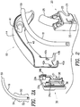
- FIG. 1 An embodiment of the laryngoscope blade of the present invention is shown in FIG. 1 and indicated by general numerical designation 10, and as indicated by the irregular line 11, is for being mounted removably to the laryngoscope handle indicated by general numerical designation 12 in FIG. 1 .
- the laryngoscope blade 10 includes a blade portion indicated by general numerical designation 14, a base portion indicted by general numerical designation 16 and an optic light pipe 18.
- the laryngoscope handle 12 may be any suitable laryngoscope handle known to the art and may be, for example, a laryngoscope handle of the type commonly referred to as Fiber Illuminated System or Green System Handles and, by way of further example, may be the laryngoscope handle available from Vital Signs, Inc., 20 Campus Road, Totowa, New Jersey, and sold under the trademark Greenlight II. Solely for purposes of illustration of the use of the laryngoscope blade 10 of the present invention, it will be assumed that the laryngoscope handle 12 of FIG. 1 is the Greenlight II laryngoscope handle, model number 4558GSP, available from Vital Signs, Inc.
- the laryngoscope handle 12 includes an upper end 12A including a hinge pin 12B and a depressible cylindrical switch element 12C, note FIG. 1A .
- the laryngoscope blade 10 is mounted removably, as described in detail below, to the handle 12 by hooking or latching the laryngoscope blade base 16 to the hinge pin 12 which is received within the inclined opening 17 provided in the base 16.
- the hinge pin 12B being received within the inclined opening 17 the laryngoscope blade 10 is pivoted into engagement with the upper end 12A of the laryngoscope handle 12 and locked into the operating or on position by engagement of the resilient ball detent 23 provided on the base portion 16 with the locking slot or detent 12F ( FIG.
- the base 16 of the laryngoscope blade 10 engages and depresses the circular depressible switch element 12C which then closes an energization circuit (not shown) in the handle 12 to illuminate a light source (not shown) in the handle which emits light which is transmitted through the circular switch element 12C and to and through the optic light pipe 18 to the distal end 19 of the laryngoscope blade to illuminate the opening to a patient's trachea.
- the blade portion 14 is made or formed from a suitable blank of 304 stainless steel using progressive dies of the type known to the art for stainless steel forming.
- the base portion 16, FIG. 1 is comprised of two base halves as shown in FIG. 2 , one base half is indicated by general numerical designation 20 and the other base half is indicated by general numerical designation 30.
- the base halves are made of ultrasonically weldable material and are ultrasonically welded together by suitable ultrasonic welding apparatus to mount the base halves to each other and to the proximal end 15, FIG. 1 , of the blade portion 14.
- the base half 20 is made of a more rigid material than the material of which the base half 30 is made and conversely, that the base half 30 is made of a more resilient material than the material of which the base half 20 is made.
- the base half 20 was made of relatively rigid glass-filled or glass reinforced nylon and the base half 30 was made of relatively resilient un-reinforced nylon; these materials are known ultrasonically weldable materials.
- the base half 20 made of such glass-filled nylon, includes a rigid hook 21 providing an inclined opening 22, a cantilever ball detent 23 surrounded by a generally U-shaped opening 24 extending through the base half 20, and a curved optic cover 25.
- the base half 20 is provided with inwardly extending alignment sockets 27a and 27b, inwardly extending tang sockets 28a and 28b, inwardly extending weld sockets 29a and 29b and an inwardly extending contoured optic channel 20a.
- the base half 30, made of such un-reinforced nylon includes a resilient cantilever latch pin 31 providing an inclined opening 32 and, as shown in FIGS. 9 and 10 , the inner surface of the base half 30 is provided with a pair of outwardly extending alignment and weld pins 33a and 33b, outwardly extending weld ribs 34a and 34b and an outwardly extending member 36 providing an inwardly extending semi-circular straight optic channel 38.
- the blade portion 14 of the laryngoscope blade 10 is shown in detail in FIGS. 12-15 with FIG. 11 being the same showing of the laryngoscope blade 10 of the present invention shown at the top of FIG. 1 but shown again for convenience of reference.
- the metal blade portion 14 includes a medial wall 40 in which an optic window 41 is formed and in which a pair of blade portion attachment thru holes 42a and 42b are formed.
- the proximal end 15 of the metal blade portion 14 is provided with a pair of perpendicularly, outwardly extending mode distribution and mounting tangs 43a and 43b. As best shown in FIG.
- the metal blade portion 14 includes a flange 44 extending outwardly perpendicularly from the medial portion 40 and which provides the distal end 19 of the laryngoscope blade 10 and which, as will be understood from FIG. 15 , provides a tongue engagement surface 45 which provides the distal end 19 of the laryngoscope blade 10 of FIG. 1 .
- the distal portion of the flange 44 is spoon-shaped to reduce the possibility of trauma to the patient's oral cavity from the intubation process upon the laryngoscope blade 10 of the present invention being utilized to insert an endotracheal tube into a patient's trachea.
- the optic light pipe 18 includes a contoured proximal portion 50 which includes a straight proximal end portion 52 and a curved distally adjacent portion 54.
- the contoured optic channel 20a, FIG. 5 , formed in the base half 20 is complimentary in shape to and for receiving the outer side, as viewed in FIG. 2 , of the contoured proximal end portion 50 of the optic light pipe 18.
- the straight optic channel 38, FIG. 10 of the base at 30, is complimentary in shape to and for receiving the inner side, as viewed in FIG. 2 , of the straight proximal end section 52 of the optic light pipe 18.
- the outer side of the contoured proximal portion 50 ( FIG. 2A ) of the light pipe 18 is inserted into the contoured optic channel 20a ( FIG. 5 ) of the base half 20, the distal end 55 of the optic light pipe 18 is inserted through the optic window 41 formed in the blade portion 14 and the tangs 43a and 43b of the blade portion 14 are inserted into the tang sockets 28a and 28b ( FIG.
- the alignment and ultrasonic weld pins 33a and 33b provided on the base half 30 are inserted through the thru holes 42a and 42b formed in the proximal end 15 of the blade portion 15 and into the weld sockets 27a and 27b ( FIG. 5 ) formed in the base half 30, and the weld ribs 34a and 34b formed on the base half 30 are inserted on to the weld sockets 29a and 29b( FIG. 5 ) formed in the base half 20.
- the inner half, as viewed in FIG. 2 the straight distal end 52 ( FIG. 2A ) of the optic light pipe 18 is received in the straight optic channel 38 formed in the base half 30.
- the base halves 20 and 30 are ultrasonically welded to each other thereby mounting the base half to each other and to the distal end 15 of the metal blade portion 14 which is captured between the ultrasonically welded base halves. Insertion of the alignment and weld pins 33a and 33b formed on the base half 30 into the weld sockets 27a and 27b formed in the base half 20, and the insertion of the weld ribs 34a and 34b formed on the base half 30 into the weld sockets 29a and 29b formed in the base half 20, align the base halves and the distal end of the blade portion 14 with respect to each other and facilitate ultrasonic welding together of the base halves.
- the curved optic cover 25 of the base half 20 covers the proximal end of the optic light pipe 18 on three sides, the outer three sides as viewed in FIG. 2 , and that the medial wall 40 of the blade portion 14 covers the fourth or inner side, as viewed in FIG. 2 , of the proximal end of the optic light pipe and hence upon light being transmitted through the optic light pipe 18 to its distal end 55 to illuminate a patient's trachea, the coverage of the distal end of the optic light pipe 18 by the optic cover 25 and the medial wall 40 of the blade portion prevents light from entering, and possibly at least partially blinding, the eyes of the laryngoscope blade 10 user during the patient intubation process.
- the diameter of the hinge pin 12B at the upper end of the handle 12 is 4.5 mm, and for the resilient cantilever latch pin 31 ( FIG.
- the width W1 of the inclined slot 32 provided by the resilient cantilever latch pin 31 is 4.0 mm, 0.5 mm smaller than the diameter of the hinge pin 12B, and as shown in FIG. 19 , the width W2 of the inclined slot 22 provided by the rigid hook 21 is 4.7 mm, 0.2 mm larger than the diameter of the hinge pin 12B, which difference causes the rigid hook 21 to loosely engage the hinge pin 12B so as not to inhibit pivoting movement between the blade 10 and handle 12 and yet permit the rigid hook 21 to engage the hinge pin 12B and withstand the force and load noted above.
- FIGS. 16 and 16A this loading and force is illustrated in FIGS. 16 and 16A .
- the laryngoscope blade 10 For insertion of an endotracheal tube (not shown) into the trachea of the patient, the laryngoscope blade 10 ( FIG. 16 ) is inserted under the patient's tongue with the distal end 19 engaging the angled area at which the epiglottis is formed at the back of the tongue, and upon the laryngoscope user, such as a physician, rotating the laryngoscope handle 12 in the direction indicated by the curved arrow 60, the laryngoscope blade 10 lifts the tongue and epiglottis of the patient to expose the trachea for the intubation process.
- the tongue exerts a force, a reaction force, F1 on the laryngoscope blade 10 and a force, a reaction force F2 (better seen in FIG. 16A ) is applied to the base 16 of the laryngoscope blade 10.
- F1 reaction force
- F2 reaction force
- it is the rigid hook 21 formed on the base half 20 that withstands the forces F1 and F2 and withstands the load applied to the laryngoscope blade 10 by such forces.
Landscapes
- Health & Medical Sciences (AREA)
- Life Sciences & Earth Sciences (AREA)
- Surgery (AREA)
- Biomedical Technology (AREA)
- Medical Informatics (AREA)
- Optics & Photonics (AREA)
- Pathology (AREA)
- Radiology & Medical Imaging (AREA)
- Biophysics (AREA)
- Engineering & Computer Science (AREA)
- Physics & Mathematics (AREA)
- Heart & Thoracic Surgery (AREA)
- Nuclear Medicine, Radiotherapy & Molecular Imaging (AREA)
- Molecular Biology (AREA)
- Animal Behavior & Ethology (AREA)
- General Health & Medical Sciences (AREA)
- Public Health (AREA)
- Veterinary Medicine (AREA)
- Otolaryngology (AREA)
- Physiology (AREA)
- Pulmonology (AREA)
- Endoscopes (AREA)
Claims (12)
- Laryngoskop-Spatel zur abnehmbaren Anbringung an einem oberen Ende eines Laryngoskop-Handgriffs (12), aufweisend einen Scharnierstift (12b), den Laryngoskop-Spatel mit einem Spatelabschnitt (14), einem Basisabschnitt (16) und einem optischen Lichtleiter (18), wobei der Spatelabschnitt ein proximales Ende (15) und ein mit einem optischen Fenster (41) versehenes distales Ende (19) aufweist, wobei der Basisabschnitt zwei Basishälften (20, 30) aufweist, die aneinander und am proximalen Ende (15) des Spatelabschnitts angebracht sind, wobei das proximale Ende (15) des Spatelabschnitts zwischen den Basishälften gefasst ist, wobei eine der Basishälften (30) aus einem Material besteht, das flexibler ist als das Material, aus dem die andere der Basishälften (20) besteht, wobei die eine Basishälfte (30) eine nachgiebigen vorkragenden Rastzapfen (31) und die andere Basishälfte (20) einen starren Haken (21) bereitstellt, und der Lichtleiter ein proximales Ende (50), das zwischen den zwei Basishälften angebracht ist, und ein distales Ende (55) aufweist, das sich durch das optische Fenster (41) erstreckt, wobei eine erste Schrägnut (32), die durch den nachgiebigen vorkragenden Rastzapfen (31) bereitgestellt ist, eine erste Breite (W1) hat, eine zweite Schrägnut (22), die durch den starren Haken (21) bereitgestellt ist, eine zweite Breite (W2) hat, die größer als die erste Breite (W1) ist, wobei die erste Breite (W1) kleiner als ein Durchmesser des Scharnierstifts (12B) und die zweite Breite (W2) größer als der Durchmesser des Scharnierstifts (12B) ist, wobei dieser Unterschied den starren Haken (21) lose am Scharnierstift (12B) angreifen lässt, um eine Schwenkbewegung zwischen dem Spatel (10) und dem Handgriff (12) nicht zu behindern und dennoch den starren Haken (21) am Scharnierstift (12B) angreifen zu lassen.
- Laryngoskop-Spatel nach Anspruch 1, wobei die andere Basishälfte (20) mit einer vorkragenden Kugelarretierung (23) versehen ist.
- Laryngoskop-Spatel nach Anspruch 1, wobei die Basishälften (20, 30) aus einem durch Ultraschall schweißbaren Material bestehen und die Basishälften mittels Ultraschall miteinander verschweißt sind.
- Laryngoskop-Spatel nach Anspruch 3, wobei die eine Basishälfte (30) aus nicht verstärktem Nylon und die andere Basishälfte (20) aus mit Glasfasern versetztem Nylon besteht.
- Laryngoskop-Spatel nach Anspruch 3, wobei die eine Basishälfte (30) eine Innenoberfläche aufweist, die mit mehreren sich nach außen erstreckenden Schweißstiften (33a, 33b) versehen ist, wobei das proximale Ende (15) des Spatelabschnitts mit mehreren Durchgangsöffnungen (42a, 42b) versehen ist, wobei die andere Basishälfte (20) eine Innenoberfläche aufweist, die mit mehreren sich nach innen erstreckenden Ausrichtaufnahmen (27a, 27b) versehen ist, und wobei die mehreren sich nach außen erstreckenden Schweißstifte sich durch die mehreren Durchgangsöffnungen hindurch in die mehreren Ausrichtaufnahmen erstrecken, um die Basishälften und das proximale Ende des Spatelabschnitts in Bezug zueinander auszurichten.
- Laryngoskop-Spatel nach Anspruch 5, wobei die Innenoberfläche der einen Basishälfte (30) mit mehreren sich nach außen erstreckenden Schweißrippen (34a, 34b) versehen ist, die Innenoberfläche der anderen Basishälfte (20) mit mehreren sich nach innen erstreckenden Schweißausnehmungen (29a, 29b) versehen ist, und wobei die sich nach außen erstreckenden Schweißrippen in die sich nach innen erstreckenden Schweißausnehmungen eingeführt werden, um die Ultraschallverschweißung der Basishälften zu verstärken.
- Laryngoskop-Spatel nach Anspruch 5, wobei das proximale Ende (15) des Spatelabschnitts mit mehreren sich nach außen erstreckenden Laschen (43a, 43b) versehen ist, wobei die Innenoberfläche der anderen Basishälfte (20) mit mehreren sich nach innen erstreckenden Ausrichtaufnahmen (28a, 28b) versehen ist, um die mehreren sich nach außen erstreckenden Laschen aufzunehmen, um zusätzlich das proximale Ende des Spatelabschnitts der anderen Basishälfte auszurichten.
- Laryngoskop-Spatel nach Anspruch 7, wobei das proximale Ende (50) des Lichtleiters eine konturierter Abschnitt mit einem geradlinigen proximalen Endabschnitt (52) und einem gekrümmten, distal angrenzenden Abschnitt (54) ist, wobei die Innenoberfläche der einen Basishälfte (30) mit einem sich nach außen erstreckenden Element versehen ist, das einen halbkreisförmigen, sich nach innen erstreckenden und geradlinigen optischen Kanal (38) zur Aufnahme einer Seite des geradlinigen proximalen Endes (52) des optischen Lichtleiters bereitstellt, und wobei die Innenoberfläche der anderen Basishälfte (20) mit einem sich nach innen erstreckenden, konturierten optischen Kanal (20a) zur Aufnahme der anderen Seite des geradlinigen proximalen Endabschnitts und einer Seite des gekrümmten, distal angrenzenden Abschnitts des konturierten Abschnitts des proximalen Endes des optischen Lichtleiters versehen ist.
- Laryngoskop-Spatel nach Anspruch 8, wobei eine Außenoberfläche der anderen Basishälfte (20) mit einer sich nach außen erstreckenden, gekrümmten optischen Abdeckung (25) zum Bedecken eines Abschnitts des proximalen Endes des optischen Lichtleiters versehen ist.
- Laryngoskop-Spatel nach Anspruch 1, wobei das distale Ende (19) des Spatelabschnitts eine löffelförmige Spitze aufweist.
- Laryngoskop-Spatel nach Anspruch 1, wobei der Laryngoskop-Spatel zum Anheben der Zunge und des Kehldeckels einer Person eine sich nach innen erstreckende Arretiernut (12f) aufweist,
wobei die eine Basishälfte (30) aus einem ausreichend nachgiebigen Material besteht, um einen nachgiebigen vorkragenden Rastzapfen (31) bereitzustellen, der in klemmender und lösbarer Weise am Scharnierstift (12b) angreift und ein Verschwenken zwischen dem Laryngoskop-Spatel und dem Laryngoskop-Handgriff ermöglicht, wobei die andere Basishälfte (20) aus einem ausreichend starren Material besteht, um einen starren Haken (21) bereitzustellen, der lose am Scharnierstift (12b) angreift und einer auf den Laryngoskop-Spatel beim Anheben der Zunge und des Kehldeckels einer Person aufgebrachten Belastung widersteht, und wobei die andere Basishälfte (20) mit einer vorkragenden Kugelarretierung (23) zum klemmenden Angriff an der Arretiernut versehen ist, um den Laryngoskop-Spatel am oberen Ende des Laryngoskop-Handgriffs zu arretieren. - Laryngoskop-Spatel nach Anspruch 1, wobei der Laryngoskop-Spatel eine sich nach innen erstreckende Arretiernut (12f) aufweist, wobei der Laryngoskop-Spatel zur Anbringung an und zum Schwenken um den Scharnierstift in Eingriff mit einem niederdrückbaren Element (12c) bestimmt ist, das am oberen Ende des Laryngoskop-Handgriffs vorgesehen ist, um einen Stromversorgungskreis für eine Lichtquelle zu schließen, die Licht aussendet, wobei auf den Laryngoskop-Spatel beim Verschwenken des Laryngoskop-Handgriffs zum Anheben der Zunge und des Kehldeckels einer Person zur Freilegung der Luftröhre der Person zum Einführen eines Endotrachealtubus eine Kraft ausgeübt wird,
wobei die eine Basishälfte(30) aus einem nachgiebigen Material besteht, um einen nachgiebigen vorkragenden Rastzapfen (31) zum klemmenden Angriff am Scharnierstift (12b) bereitzustellen, um den Laryngoskop-Spatel lösbar und schwenkbar am Scharnierstift anzubringen, wobei die andere Basishälfte (20) aus einem ausreichend starren Material besteht, um einen starren Haken (21) bereitzustellen, der eine Schrägnut (22) zur Aufnahme des Scharnierstifts und zum nicht zu straffen Angriff an demselben bereitstellt, wobei der starre Haken dazu dient, der Kraft zu widerstehen, die beim Anheben der Zunge und des Kehldeckels einer Person auf den Laryngoskop-Spatel aufgebracht wird, wobei die andere Basishälfte (20) eine vorkragende Kugelarretierung (23) zum klemmenden Angriff an der Arretiernut bereitstellt, um den Laryngoskop-Spatel in einer Betriebsposition am oberen Ende des Laryngoskop-Handgriffs zu arretieren.
Applications Claiming Priority (2)
| Application Number | Priority Date | Filing Date | Title |
|---|---|---|---|
| US11/726,689 US7611459B2 (en) | 2007-03-22 | 2007-03-22 | Laryngoscope blade |
| PCT/US2008/057549 WO2008118719A1 (en) | 2007-03-22 | 2008-03-19 | Laryngoscope blade |
Publications (3)
| Publication Number | Publication Date |
|---|---|
| EP2129276A1 EP2129276A1 (de) | 2009-12-09 |
| EP2129276A4 EP2129276A4 (de) | 2013-04-03 |
| EP2129276B1 true EP2129276B1 (de) | 2017-12-13 |
Family
ID=39775439
Family Applications (1)
| Application Number | Title | Priority Date | Filing Date |
|---|---|---|---|
| EP08732501.5A Not-in-force EP2129276B1 (de) | 2007-03-22 | 2008-03-19 | Laryngoskopklinge |
Country Status (4)
| Country | Link |
|---|---|
| US (3) | US7611459B2 (de) |
| EP (1) | EP2129276B1 (de) |
| ES (1) | ES2662075T3 (de) |
| WO (1) | WO2008118719A1 (de) |
Families Citing this family (25)
| Publication number | Priority date | Publication date | Assignee | Title |
|---|---|---|---|---|
| GB0718268D0 (en) | 2007-09-19 | 2008-10-08 | Ayrshire And Arran Health Board | Retractor with integrated light source |
| US20100217085A1 (en) * | 2009-02-20 | 2010-08-26 | Hartwell Medical Corporation | Laryngoscope Blade |
| USD634008S1 (en) * | 2009-12-21 | 2011-03-08 | Intubrite, Llc | Laryngoscope blade |
| USD630739S1 (en) * | 2009-12-21 | 2011-01-11 | Intubrite, Llc | Laryngoscope blade |
| US9289114B2 (en) * | 2010-07-30 | 2016-03-22 | Nilesh R. Vasan | Disposable, self-contained laryngoscope and method of using same |
| USD739017S1 (en) * | 2011-09-20 | 2015-09-15 | Karl Storz Gmbh & Co. Kg | Laryngoscope blade with handle |
| USD738501S1 (en) * | 2011-09-20 | 2015-09-08 | Karl Storz Gmbh & Co. Kg | Laryngoscope blade with handle |
| PT106730A (pt) * | 2013-01-10 | 2014-07-10 | Univ Do Porto | Laringoscópio digital |
| WO2015033334A1 (en) * | 2013-09-03 | 2015-03-12 | Truphatek International Ltd | Single use laryngoscope handle |
| WO2015156818A1 (en) * | 2014-04-11 | 2015-10-15 | Nissan North America, Inc. | Autonomous vehicle control system |
| USD767758S1 (en) * | 2014-07-03 | 2016-09-27 | Evgeny Pecherer | Laryngoscope |
| USD766431S1 (en) * | 2014-07-07 | 2016-09-13 | Evgeny Pecherer | Laryngoscope handle |
| GB2532239A (en) | 2014-11-12 | 2016-05-18 | Clear Surgical Ltd | Retractor with improved light source, and light source for an improved retractor |
| CN105231984A (zh) * | 2015-11-02 | 2016-01-13 | 西安索格医疗科技有限公司 | 一次性使用的喉镜镜片 |
| US10334687B2 (en) * | 2017-04-20 | 2019-06-25 | Ngok Wing Jimmy Kwok | Multispectral switch fiber optic lighting laryngoscope |
| USD863555S1 (en) | 2018-07-30 | 2019-10-15 | Teleflex Medical Incorporated | Laryngoscope blade |
| USD862696S1 (en) | 2018-07-30 | 2019-10-08 | Teleflex Medical Incorporated | Laryngoscope blade |
| CN112930134B (zh) * | 2018-07-30 | 2025-10-28 | 泰利福医疗公司 | 带光导的喉镜刀片 |
| USD876625S1 (en) | 2018-08-07 | 2020-02-25 | Adroit Surgical, Llc | Laryngoscope |
| CN119488268A (zh) | 2019-03-14 | 2025-02-21 | 泰利福医疗公司 | 通用喉镜窥视片 |
| USD950054S1 (en) * | 2019-04-03 | 2022-04-26 | Flexicare (Group) Limited | Laryngoscope blade |
| USD950724S1 (en) * | 2019-04-03 | 2022-05-03 | Flexicare (Group) Limited | Laryngoscope blade |
| USD930157S1 (en) * | 2020-02-07 | 2021-09-07 | Tien-Sheng Chen | Laryngoscope blade |
| USD940314S1 (en) * | 2020-06-16 | 2022-01-04 | Tien-Sheng Chen | Laryngoscope blade |
| US20240366081A1 (en) * | 2023-05-05 | 2024-11-07 | Children's National Medical Center | Laryngoscope and uses thereof |
Family Cites Families (38)
| Publication number | Priority date | Publication date | Assignee | Title |
|---|---|---|---|---|
| US2354471A (en) | 1943-08-18 | 1944-07-25 | Foregger Company Inc | Laryngoscope |
| US3760798A (en) * | 1971-11-24 | 1973-09-25 | L Edinger | Self-illuminating tongue depressor and the like |
| US4344419A (en) * | 1979-12-20 | 1982-08-17 | Kermit Burgin | Acrylooptic tongue depressor and handle therefor |
| US4570614A (en) * | 1983-05-06 | 1986-02-18 | Jack Bauman | Laryngoscope with disposable blade and light conductor |
| US4565187A (en) * | 1984-09-04 | 1986-01-21 | Soloway David J | Laryngoscope |
| US4607623A (en) * | 1984-11-08 | 1986-08-26 | Jack Bauman | Unitary insert support frame for the handle of an examining device |
| US4681094A (en) * | 1985-11-27 | 1987-07-21 | American Medical And Emergency Research Corporation | Balloon laryngoscope |
| US4958624A (en) * | 1989-03-31 | 1990-09-25 | Welch Allyn, Inc. | Interchangeable laryngeal blade |
| US5065738A (en) * | 1990-01-16 | 1991-11-19 | Dam David J Van | Laryngoscope blade sheath |
| US5060633A (en) * | 1990-08-31 | 1991-10-29 | Gibson Michael S | Laryngoscope blade |
| US5367440A (en) * | 1992-08-14 | 1994-11-22 | Eastman Kodak Company | Flexible fiber optic illuminator and method |
| US5318009A (en) * | 1993-03-03 | 1994-06-07 | Scientific Medical Programs, Inc. | Illuminated tongue depressor |
| IL107594A (en) | 1993-11-12 | 1997-06-10 | Truphatek Int Ltd | Laryngoscope |
| US5645519A (en) * | 1994-03-18 | 1997-07-08 | Jai S. Lee | Endoscopic instrument for controlled introduction of tubular members in the body and methods therefor |
| US5651760A (en) * | 1995-03-20 | 1997-07-29 | Upsher Laryngoscope Corporation | Laryngoscope including means for locking the blade in an operative position |
| US5702351A (en) | 1995-08-23 | 1997-12-30 | Bar-Or; David | Laryngoscope and disposable blade therefor |
| US6013020A (en) * | 1996-09-23 | 2000-01-11 | Novoste Corporation | Intraluminal radiation treatment system |
| US6013026A (en) | 1999-02-25 | 2000-01-11 | Welch Allyn, Inc. | Releasable laryngeal blade assembly and set of laryngoscopes |
| US6890298B2 (en) * | 1999-10-14 | 2005-05-10 | Karl Storz Gmbh & Co. Kg | Video laryngoscope with detachable light and image guides |
| US6213937B1 (en) | 2000-07-21 | 2001-04-10 | Welch Allyn, Inc. | Toolless light pipe mount for laryngoscope and method for releasably attaching |
| US6623425B2 (en) * | 2001-07-23 | 2003-09-23 | Cartledge Medical Products, Llc | Modified laryngoscope blade to reduce dental injuries during intubation |
| FR2828263B1 (fr) * | 2001-08-03 | 2007-05-11 | Philipp Bonhoeffer | Dispositif d'implantation d'un implant et procede d'implantation du dispositif |
| IL146569A0 (en) * | 2001-11-19 | 2002-07-25 | Truphatek Int Ltd | Light guide assembly for use with a laryngoscope |
| US6626829B1 (en) * | 2002-03-05 | 2003-09-30 | Eddie W. Skaggs | Laryngoscope and method |
| USD491267S1 (en) | 2002-06-28 | 2004-06-08 | Hilbro Instruments Pvt (Ltd.) | Laryngoscope blade |
| USD512778S1 (en) | 2002-12-06 | 2005-12-13 | Hilbro Instruments (Pvt) Ltd. | Laryngoscope blade |
| US7608040B1 (en) * | 2003-02-24 | 2009-10-27 | City Of Hope | Device to aid in placing tracheal tubes |
| US7399315B2 (en) * | 2003-03-18 | 2008-07-15 | Edwards Lifescience Corporation | Minimally-invasive heart valve with cusp positioners |
| US7128710B1 (en) | 2003-08-08 | 2006-10-31 | Azimuth Corporation | Disposable laryngoscope blades |
| US7748389B2 (en) * | 2003-12-23 | 2010-07-06 | Sadra Medical, Inc. | Leaflet engagement elements and methods for use thereof |
| US20050137686A1 (en) * | 2003-12-23 | 2005-06-23 | Sadra Medical, A Delaware Corporation | Externally expandable heart valve anchor and method |
| US8828078B2 (en) * | 2003-12-23 | 2014-09-09 | Sadra Medical, Inc. | Methods and apparatus for endovascular heart valve replacement comprising tissue grasping elements |
| US7736304B2 (en) * | 2004-02-29 | 2010-06-15 | Truphatek International Ltd. | Metal laryngoscope blade |
| US7153260B1 (en) | 2004-03-01 | 2006-12-26 | Magdy S Girgis | Laryngoscope for simultaneously facilitating the illuminating of a throat pathway and inserting an intubation tube |
| US20070213813A1 (en) * | 2005-12-22 | 2007-09-13 | Symetis Sa | Stent-valves for valve replacement and associated methods and systems for surgery |
| US8052750B2 (en) * | 2006-09-19 | 2011-11-08 | Medtronic Ventor Technologies Ltd | Valve prosthesis fixation techniques using sandwiching |
| US7695433B2 (en) * | 2007-01-24 | 2010-04-13 | Zeppelin Designs, Inc. | Laryngoscope with disposable blade cover |
| US9138315B2 (en) * | 2007-04-13 | 2015-09-22 | Jenavalve Technology Gmbh | Medical device for treating a heart valve insufficiency or stenosis |
-
2007
- 2007-03-22 US US11/726,689 patent/US7611459B2/en not_active Expired - Fee Related
-
2008
- 2008-03-19 WO PCT/US2008/057549 patent/WO2008118719A1/en not_active Ceased
- 2008-03-19 ES ES08732501.5T patent/ES2662075T3/es active Active
- 2008-03-19 EP EP08732501.5A patent/EP2129276B1/de not_active Not-in-force
-
2009
- 2009-10-05 US US12/573,190 patent/US8702598B2/en active Active
-
2014
- 2014-04-21 US US14/257,979 patent/US9510745B2/en active Active
Non-Patent Citations (1)
| Title |
|---|
| None * |
Also Published As
| Publication number | Publication date |
|---|---|
| US7611459B2 (en) | 2009-11-03 |
| US8702598B2 (en) | 2014-04-22 |
| US20100022842A1 (en) | 2010-01-28 |
| WO2008118719A1 (en) | 2008-10-02 |
| EP2129276A4 (de) | 2013-04-03 |
| EP2129276A1 (de) | 2009-12-09 |
| US9510745B2 (en) | 2016-12-06 |
| ES2662075T3 (es) | 2018-04-05 |
| US20140221755A1 (en) | 2014-08-07 |
| US20080234549A1 (en) | 2008-09-25 |
Similar Documents
| Publication | Publication Date | Title |
|---|---|---|
| EP2129276B1 (de) | Laryngoskopklinge | |
| US12569126B2 (en) | Disposable, self-contained laryngoscope and method of using same | |
| US11510563B2 (en) | Laryngoscope insertion section structure | |
| US6213937B1 (en) | Toolless light pipe mount for laryngoscope and method for releasably attaching | |
| JP5596127B2 (ja) | 喉頭鏡 | |
| US6248061B1 (en) | Suctioning laryngoscope blade | |
| CN109475268B (zh) | 喉镜 | |
| US7044909B2 (en) | Video laryngoscope with detachable light and image guides | |
| EP3554604B1 (de) | Vorrichtung zum einführen eines endotrachealtubus | |
| US4573451A (en) | Laryngoscope blade with a bendable tip | |
| EP1738789A1 (de) | Endotracheale Videovorrichtung | |
| US20200275830A1 (en) | Medical device with an airway insertion member | |
| US7153260B1 (en) | Laryngoscope for simultaneously facilitating the illuminating of a throat pathway and inserting an intubation tube | |
| US20100004514A1 (en) | Intubation laryngoscope with two-sided blade | |
| US9386915B2 (en) | Disposable, self-contained laryngoscope and method of using same | |
| EP3806941A1 (de) | Einsetzvorrichtung für endotrachealtubus | |
| US20060183978A1 (en) | Laryngoscope | |
| JP2009160224A (ja) | 分離型内視鏡 | |
| WO2022259549A1 (ja) | 先端カバーおよび内視鏡装置 | |
| RU229152U1 (ru) | Видеоларингоскоп | |
| JP2003116778A (ja) | 挿管用内視鏡 |
Legal Events
| Date | Code | Title | Description |
|---|---|---|---|
| PUAI | Public reference made under article 153(3) epc to a published international application that has entered the european phase |
Free format text: ORIGINAL CODE: 0009012 |
|
| 17P | Request for examination filed |
Effective date: 20091022 |
|
| AK | Designated contracting states |
Kind code of ref document: A1 Designated state(s): AT BE BG CH CY CZ DE DK EE ES FI FR GB GR HR HU IE IS IT LI LT LU LV MC MT NL NO PL PT RO SE SI SK TR |
|
| DAX | Request for extension of the european patent (deleted) | ||
| A4 | Supplementary search report drawn up and despatched |
Effective date: 20130306 |
|
| RIC1 | Information provided on ipc code assigned before grant |
Ipc: A61B 1/07 20060101ALI20130228BHEP Ipc: A61B 1/267 20060101AFI20130228BHEP Ipc: A61B 1/273 20060101ALI20130228BHEP Ipc: A61B 1/00 20060101ALI20130228BHEP |
|
| 17Q | First examination report despatched |
Effective date: 20160519 |
|
| GRAP | Despatch of communication of intention to grant a patent |
Free format text: ORIGINAL CODE: EPIDOSNIGR1 |
|
| INTG | Intention to grant announced |
Effective date: 20170704 |
|
| GRAS | Grant fee paid |
Free format text: ORIGINAL CODE: EPIDOSNIGR3 |
|
| GRAA | (expected) grant |
Free format text: ORIGINAL CODE: 0009210 |
|
| AK | Designated contracting states |
Kind code of ref document: B1 Designated state(s): AT BE BG CH CY CZ DE DK EE ES FI FR GB GR HR HU IE IS IT LI LT LU LV MC MT NL NO PL PT RO SE SI SK TR |
|
| REG | Reference to a national code |
Ref country code: GB Ref legal event code: FG4D |
|
| REG | Reference to a national code |
Ref country code: AT Ref legal event code: REF Ref document number: 953586 Country of ref document: AT Kind code of ref document: T Effective date: 20171215 Ref country code: CH Ref legal event code: EP |
|
| REG | Reference to a national code |
Ref country code: IE Ref legal event code: FG4D |
|
| REG | Reference to a national code |
Ref country code: DE Ref legal event code: R096 Ref document number: 602008053330 Country of ref document: DE |
|
| REG | Reference to a national code |
Ref country code: FR Ref legal event code: PLFP Year of fee payment: 11 |
|
| REG | Reference to a national code |
Ref country code: ES Ref legal event code: FG2A Ref document number: 2662075 Country of ref document: ES Kind code of ref document: T3 Effective date: 20180405 |
|
| REG | Reference to a national code |
Ref country code: NL Ref legal event code: MP Effective date: 20171213 |
|
| REG | Reference to a national code |
Ref country code: LT Ref legal event code: MG4D |
|
| PG25 | Lapsed in a contracting state [announced via postgrant information from national office to epo] |
Ref country code: LT Free format text: LAPSE BECAUSE OF FAILURE TO SUBMIT A TRANSLATION OF THE DESCRIPTION OR TO PAY THE FEE WITHIN THE PRESCRIBED TIME-LIMIT Effective date: 20171213 Ref country code: SE Free format text: LAPSE BECAUSE OF FAILURE TO SUBMIT A TRANSLATION OF THE DESCRIPTION OR TO PAY THE FEE WITHIN THE PRESCRIBED TIME-LIMIT Effective date: 20171213 Ref country code: NO Free format text: LAPSE BECAUSE OF FAILURE TO SUBMIT A TRANSLATION OF THE DESCRIPTION OR TO PAY THE FEE WITHIN THE PRESCRIBED TIME-LIMIT Effective date: 20180313 Ref country code: FI Free format text: LAPSE BECAUSE OF FAILURE TO SUBMIT A TRANSLATION OF THE DESCRIPTION OR TO PAY THE FEE WITHIN THE PRESCRIBED TIME-LIMIT Effective date: 20171213 |
|
| REG | Reference to a national code |
Ref country code: AT Ref legal event code: MK05 Ref document number: 953586 Country of ref document: AT Kind code of ref document: T Effective date: 20171213 |
|
| PG25 | Lapsed in a contracting state [announced via postgrant information from national office to epo] |
Ref country code: GR Free format text: LAPSE BECAUSE OF FAILURE TO SUBMIT A TRANSLATION OF THE DESCRIPTION OR TO PAY THE FEE WITHIN THE PRESCRIBED TIME-LIMIT Effective date: 20180314 Ref country code: HR Free format text: LAPSE BECAUSE OF FAILURE TO SUBMIT A TRANSLATION OF THE DESCRIPTION OR TO PAY THE FEE WITHIN THE PRESCRIBED TIME-LIMIT Effective date: 20171213 Ref country code: LV Free format text: LAPSE BECAUSE OF FAILURE TO SUBMIT A TRANSLATION OF THE DESCRIPTION OR TO PAY THE FEE WITHIN THE PRESCRIBED TIME-LIMIT Effective date: 20171213 Ref country code: BG Free format text: LAPSE BECAUSE OF FAILURE TO SUBMIT A TRANSLATION OF THE DESCRIPTION OR TO PAY THE FEE WITHIN THE PRESCRIBED TIME-LIMIT Effective date: 20180313 |
|
| PG25 | Lapsed in a contracting state [announced via postgrant information from national office to epo] |
Ref country code: NL Free format text: LAPSE BECAUSE OF FAILURE TO SUBMIT A TRANSLATION OF THE DESCRIPTION OR TO PAY THE FEE WITHIN THE PRESCRIBED TIME-LIMIT Effective date: 20171213 |
|
| PG25 | Lapsed in a contracting state [announced via postgrant information from national office to epo] |
Ref country code: SK Free format text: LAPSE BECAUSE OF FAILURE TO SUBMIT A TRANSLATION OF THE DESCRIPTION OR TO PAY THE FEE WITHIN THE PRESCRIBED TIME-LIMIT Effective date: 20171213 Ref country code: CZ Free format text: LAPSE BECAUSE OF FAILURE TO SUBMIT A TRANSLATION OF THE DESCRIPTION OR TO PAY THE FEE WITHIN THE PRESCRIBED TIME-LIMIT Effective date: 20171213 Ref country code: CY Free format text: LAPSE BECAUSE OF FAILURE TO SUBMIT A TRANSLATION OF THE DESCRIPTION OR TO PAY THE FEE WITHIN THE PRESCRIBED TIME-LIMIT Effective date: 20171213 Ref country code: EE Free format text: LAPSE BECAUSE OF FAILURE TO SUBMIT A TRANSLATION OF THE DESCRIPTION OR TO PAY THE FEE WITHIN THE PRESCRIBED TIME-LIMIT Effective date: 20171213 |
|
| PG25 | Lapsed in a contracting state [announced via postgrant information from national office to epo] |
Ref country code: PL Free format text: LAPSE BECAUSE OF FAILURE TO SUBMIT A TRANSLATION OF THE DESCRIPTION OR TO PAY THE FEE WITHIN THE PRESCRIBED TIME-LIMIT Effective date: 20171213 Ref country code: IS Free format text: LAPSE BECAUSE OF FAILURE TO SUBMIT A TRANSLATION OF THE DESCRIPTION OR TO PAY THE FEE WITHIN THE PRESCRIBED TIME-LIMIT Effective date: 20180413 Ref country code: RO Free format text: LAPSE BECAUSE OF FAILURE TO SUBMIT A TRANSLATION OF THE DESCRIPTION OR TO PAY THE FEE WITHIN THE PRESCRIBED TIME-LIMIT Effective date: 20171213 Ref country code: AT Free format text: LAPSE BECAUSE OF FAILURE TO SUBMIT A TRANSLATION OF THE DESCRIPTION OR TO PAY THE FEE WITHIN THE PRESCRIBED TIME-LIMIT Effective date: 20171213 |
|
| REG | Reference to a national code |
Ref country code: DE Ref legal event code: R097 Ref document number: 602008053330 Country of ref document: DE |
|
| PLBE | No opposition filed within time limit |
Free format text: ORIGINAL CODE: 0009261 |
|
| STAA | Information on the status of an ep patent application or granted ep patent |
Free format text: STATUS: NO OPPOSITION FILED WITHIN TIME LIMIT |
|
| REG | Reference to a national code |
Ref country code: CH Ref legal event code: PL |
|
| 26N | No opposition filed |
Effective date: 20180914 |
|
| PG25 | Lapsed in a contracting state [announced via postgrant information from national office to epo] |
Ref country code: MC Free format text: LAPSE BECAUSE OF FAILURE TO SUBMIT A TRANSLATION OF THE DESCRIPTION OR TO PAY THE FEE WITHIN THE PRESCRIBED TIME-LIMIT Effective date: 20171213 Ref country code: DK Free format text: LAPSE BECAUSE OF FAILURE TO SUBMIT A TRANSLATION OF THE DESCRIPTION OR TO PAY THE FEE WITHIN THE PRESCRIBED TIME-LIMIT Effective date: 20171213 |
|
| REG | Reference to a national code |
Ref country code: BE Ref legal event code: MM Effective date: 20180331 |
|
| REG | Reference to a national code |
Ref country code: IE Ref legal event code: MM4A |
|
| PG25 | Lapsed in a contracting state [announced via postgrant information from national office to epo] |
Ref country code: LU Free format text: LAPSE BECAUSE OF NON-PAYMENT OF DUE FEES Effective date: 20180319 |
|
| PG25 | Lapsed in a contracting state [announced via postgrant information from national office to epo] |
Ref country code: IE Free format text: LAPSE BECAUSE OF NON-PAYMENT OF DUE FEES Effective date: 20180319 |
|
| PG25 | Lapsed in a contracting state [announced via postgrant information from national office to epo] |
Ref country code: BE Free format text: LAPSE BECAUSE OF NON-PAYMENT OF DUE FEES Effective date: 20180331 Ref country code: SI Free format text: LAPSE BECAUSE OF FAILURE TO SUBMIT A TRANSLATION OF THE DESCRIPTION OR TO PAY THE FEE WITHIN THE PRESCRIBED TIME-LIMIT Effective date: 20171213 Ref country code: LI Free format text: LAPSE BECAUSE OF NON-PAYMENT OF DUE FEES Effective date: 20180331 Ref country code: CH Free format text: LAPSE BECAUSE OF NON-PAYMENT OF DUE FEES Effective date: 20180331 |
|
| PG25 | Lapsed in a contracting state [announced via postgrant information from national office to epo] |
Ref country code: MT Free format text: LAPSE BECAUSE OF NON-PAYMENT OF DUE FEES Effective date: 20180319 |
|
| PG25 | Lapsed in a contracting state [announced via postgrant information from national office to epo] |
Ref country code: TR Free format text: LAPSE BECAUSE OF FAILURE TO SUBMIT A TRANSLATION OF THE DESCRIPTION OR TO PAY THE FEE WITHIN THE PRESCRIBED TIME-LIMIT Effective date: 20171213 |
|
| PGFP | Annual fee paid to national office [announced via postgrant information from national office to epo] |
Ref country code: DE Payment date: 20200218 Year of fee payment: 13 Ref country code: GB Payment date: 20200221 Year of fee payment: 13 Ref country code: IT Payment date: 20200218 Year of fee payment: 13 |
|
| PG25 | Lapsed in a contracting state [announced via postgrant information from national office to epo] |
Ref country code: HU Free format text: LAPSE BECAUSE OF FAILURE TO SUBMIT A TRANSLATION OF THE DESCRIPTION OR TO PAY THE FEE WITHIN THE PRESCRIBED TIME-LIMIT; INVALID AB INITIO Effective date: 20080319 Ref country code: PT Free format text: LAPSE BECAUSE OF FAILURE TO SUBMIT A TRANSLATION OF THE DESCRIPTION OR TO PAY THE FEE WITHIN THE PRESCRIBED TIME-LIMIT Effective date: 20171213 |
|
| PGFP | Annual fee paid to national office [announced via postgrant information from national office to epo] |
Ref country code: FR Payment date: 20200220 Year of fee payment: 13 |
|
| PGFP | Annual fee paid to national office [announced via postgrant information from national office to epo] |
Ref country code: ES Payment date: 20200401 Year of fee payment: 13 |
|
| REG | Reference to a national code |
Ref country code: DE Ref legal event code: R119 Ref document number: 602008053330 Country of ref document: DE |
|
| GBPC | Gb: european patent ceased through non-payment of renewal fee |
Effective date: 20210319 |
|
| PG25 | Lapsed in a contracting state [announced via postgrant information from national office to epo] |
Ref country code: DE Free format text: LAPSE BECAUSE OF NON-PAYMENT OF DUE FEES Effective date: 20211001 Ref country code: FR Free format text: LAPSE BECAUSE OF NON-PAYMENT OF DUE FEES Effective date: 20210331 Ref country code: GB Free format text: LAPSE BECAUSE OF NON-PAYMENT OF DUE FEES Effective date: 20210319 |
|
| PG25 | Lapsed in a contracting state [announced via postgrant information from national office to epo] |
Ref country code: IT Free format text: LAPSE BECAUSE OF NON-PAYMENT OF DUE FEES Effective date: 20210319 |
|
| REG | Reference to a national code |
Ref country code: ES Ref legal event code: FD2A Effective date: 20220523 |
|
| PG25 | Lapsed in a contracting state [announced via postgrant information from national office to epo] |
Ref country code: ES Free format text: LAPSE BECAUSE OF NON-PAYMENT OF DUE FEES Effective date: 20210320 |