EP2129206A2 - High frequency unit - Google Patents
High frequency unit Download PDFInfo
- Publication number
- EP2129206A2 EP2129206A2 EP09006974A EP09006974A EP2129206A2 EP 2129206 A2 EP2129206 A2 EP 2129206A2 EP 09006974 A EP09006974 A EP 09006974A EP 09006974 A EP09006974 A EP 09006974A EP 2129206 A2 EP2129206 A2 EP 2129206A2
- Authority
- EP
- European Patent Office
- Prior art keywords
- mounting plate
- circuit board
- high frequency
- coaxial connector
- shield case
- Prior art date
- Legal status (The legal status is an assumption and is not a legal conclusion. Google has not performed a legal analysis and makes no representation as to the accuracy of the status listed.)
- Withdrawn
Links
- 238000005192 partition Methods 0.000 claims abstract description 27
- 239000002184 metal Substances 0.000 claims abstract description 26
- 230000002093 peripheral effect Effects 0.000 claims abstract description 17
- 238000000638 solvent extraction Methods 0.000 claims abstract description 5
- 238000003825 pressing Methods 0.000 claims description 8
- 230000000694 effects Effects 0.000 description 6
- 230000003014 reinforcing effect Effects 0.000 description 3
- 230000000717 retained effect Effects 0.000 description 3
- 238000000034 method Methods 0.000 description 2
- 238000005452 bending Methods 0.000 description 1
- 239000004020 conductor Substances 0.000 description 1
- 238000004519 manufacturing process Methods 0.000 description 1
- 238000012986 modification Methods 0.000 description 1
- 230000004048 modification Effects 0.000 description 1
- 230000000149 penetrating effect Effects 0.000 description 1
Images

Classifications
-
- H—ELECTRICITY
- H05—ELECTRIC TECHNIQUES NOT OTHERWISE PROVIDED FOR
- H05K—PRINTED CIRCUITS; CASINGS OR CONSTRUCTIONAL DETAILS OF ELECTRIC APPARATUS; MANUFACTURE OF ASSEMBLAGES OF ELECTRICAL COMPONENTS
- H05K9/00—Screening of apparatus or components against electric or magnetic fields
- H05K9/0007—Casings
- H05K9/002—Casings with localised screening
- H05K9/0022—Casings with localised screening of components mounted on printed circuit boards [PCB]
Definitions
- the present invention contains subject matter related to Japanese Patent Application No. 2008-142782 filed in the Japanese Patent Office on May 30, 2008, the entire contents of which being incorporated herein by reference.
- the present invention relates to a high frequency unit in which a coaxial connector is fixed to a mounting plate that is supported by side walls of a shield case enclosing a circuit board to face the circuit board, and the coaxial connector being attached to or detached from an external connector.
- an outer edge of a mounting plate extending from side walls of a shield case along a circuit board is supported by the side walls or a partition wall, so that a coaxial connector fixed to the mounting plate is stably supported.
- the partition wall is a metal plate partitioning a space on the circuit board and fixed to the side walls of the shield case.
- a high frequency circuit unit such as a tuner circuit is formed on the circuit board, and a core extending from the coaxial connector toward the circuit board is soldered to a connection land of the high frequency circuit unit (for example, refer to Japanese Patent No. 4020743 ).
- a longitudinal dimension of the mounting plate is the same as a longitudinal dimension of a longer side of the side wall of the shield case, so that the area of the mounting plate is large.
- a high frequency unit having a configuration in which a coaxial connector is fixed to a mounting plate with a relatively smaller area has been widely used.
- an outer edge of the mounting plate is supported by one or two adjacent side walls of a shield case and a partition wall, and thus the mounting plate has a narrow width that is slightly greater than an outer diameter of the coaxial connector.
- an open end of the shield case at which the mounting plate is disposed is generally covered by a sheet metal cover provided with a through-hole through which a coaxial connector penetrates.
- the sheet metal cover covers the shield case while overlapping with the mounting plate and is fitted to the side walls of the shield case.
- peripheral portions that are easily deformed exist at the outer edge of the mounting plate. Therefore, there was a concern that, when attaching or detaching the external connector, the mounting plate is deformed and the junction of the core of the coaxial connector and the circuit board may be broken down.
- a high frequency unit including: a shield case having a frame shape enclosing a circuit board with a plurality of side walls; a partition wall for partitioning a space on the circuit board; a mounting plate made of a metal sheet supported by the partition wall and the side walls of the shield case; and a coaxial connector fixed to the mounting plate to protrude outward, wherein a core extending from the coaxial connector toward the circuit board is connected to a high frequency circuit unit of the circuit board, and a side plate extends from a peripheral portion, which is not supported by the side walls and the partition wall, of an outer edge of the mounting plate, to be bent toward the circuit board.
- three peripheral portions of the rectangular mounting plate may be supported by the two adjacent side walls of the shield case and the partition wall, and the side plate may extend from the remaining one peripheral portion of the mounting plate. Therefore, mechanical strength of the mounting plate can be enhanced, and the mounting plate is hardly deformed, which is preferable.
- the side plate of the mounting plate may have a leg portion, and the leg portion may be soldered to a ground circuit unit of the circuit board. Accordingly, the side plate is retained by the circuit board with the leg portion interposed therebetween, so that the mounting plate is hardly deformed. In addition, the side plate is electrically connected to the ground circuit unit with the leg portion interposed therebetween, and a shield effect on the core can further be increased.
- a sheet metal cover which has a through-hole through which the coaxial connector penetrates, and overlaps with the mounting plate to cover an open end of the shield case may further be included, wherein the sheet metal cover is provided with a jetty portion extending from a periphery of the through-hole to be bent toward the mounting plate such that the jetty portion comes in pressing contact with the mounting plate Therefore, a risk that internal high frequency waves and harmonic waves thereof leak through the through-hole and may affect the coaxial connector is small, and mechanical strength of the sheet metal cover can be enhanced due to the jetty portion.
- the mounting plate is hardly deformed, which means that the jetty portion comes in pressing contact with the mounting plate by being taken into the mounting plate.
- the side plate extending from the peripheral portion, which is not supported by the side walls of the shield case and the partition wall, of the outer edge of the mounting plate, functions as a reinforcing rib, so that the coaxial connector can be fixed to the mounting plate which has a relatively smaller area and is hardly deformed. Accordingly, at low cost, it is possible to effectively suppress deformation of the mounting plate which needs to be concerned when attaching or detaching an external connector, and reliability of a connection between the core of the coaxial connector and the circuit board can be increased.
- the core of the coaxial connector can be enclosed by the side plate of the mounting plate, the side walls of the shield case, and the partition wall. Therefore, a shield effect on the core can be enhanced, and an RF signal is not easily influenced by noises.
- Fig. 1 is a plan view illustrating a main part of a high frequency unit according to a first embodiment of the invention, where a sheet metal cover is omitted.
- Fig. 2 is a cross-sectional view taken along line A-A of Fig. 1.
- Fig. 3 is a cross-sectional view taken along line B-B of Fig. 1 .
- the high frequency unit illustrated in Figs. 1 to 3 schematically includes a circuit board 1 on which a high frequency circuit unit such as a tuner circuit is formed, a shield case 2 having a frame shape enclosing the circuit board 1 with four side walls 2a (here, one of the side walls is not shown), a partition wall 3 for partitioning a space on the circuit board 1, a mounting plate 4 which faces the circuit board 1 and of which an outer edge is supported by the side walls 2a or the partition wall 3, a coaxial connector 5 fixed to the mounting plate 4 to protrude outward, a sheet metal cover 6 covering an upper open end of the shield case 2, and a lower cover 7 covering a lower open end of the shield case 2.
- the shield case 2, the sheet metal cover 6, and the lower cover 7 are formed by pressing metal sheets, and constitute a housing almost completely covering the circuit board 1.
- the partition wall 3 is a metal plate fixed to the shield case 2, and a plurality of the partition walls 3 are provided on the circuit board 1.
- the mounting plate 4 is a rectangular metal sheet extending from one of the side walls 2a of the shield case 2 along the circuit board 1, and three peripheral portions of the outer edge thereof are supported by the two adjacent side walls 2a and the partition wall 3.
- a side plate 4a made of a metal piece bent toward the circuit board 1 extends from the one remaining peripheral portion of the mounting plate 4.
- a core 5a of the coaxial connector 5 fixed to the mounting plate 4 extends toward the circuit board 1 to be soldered to a connection land of the high frequency circuit unit.
- an external conductor of the coaxial connector 5 is soldered to the mounting plate 4.
- An external connector not shown is mounted to the coaxial connector 5.
- the sheet metal cover 6 is provided with a through-hole 6a through which the coaxial connector 5 penetrates, a jetty portion 6b which extends from a periphery of the through-hole 6a to be bent toward the mounting plate 4, and a plurality of engagement protrusions 6c to be engaged with the side wall 2a of the shield case 2.
- the engagement protrusion 6c is engaged with the side wall 2a such that the sheet metal cover 6 is fitted to the shield case 2, and the upper open end of the shield case 2 is covered by the sheet metal cover 6 overlapping with the mounting plate 4.
- the jetty portion 6b comes in pressing contact with the mounting plate 4.
- the remaining peripheral portion which is not supported by the two side walls 2a and the partition wall 3 is provided with the bent side plate 4a, and the side plate 4a functions as a reinforcing rib, so that the coaxial connector 5 can be fixed to the mounting plate 4 which has a relatively smaller area and is hardly deformed. Accordingly, it is possible to effectively suppress deformation of the mounting plate 4 which needs to be concerned when the external connector is attached to or detached from the coaxial connector 5, and reliability of a connection between the core 5a of the coaxial connector 5 and the high frequency circuit unit of the circuit board 1 can be increased.
- the side plate 4a it is possible to easily form the side plate 4a at the peripheral portion of the mounting plate 4 by pressing, so that there is no concern about an increase in manufacturing costs.
- the core 5a of the coaxial connector 5 can be enclosed by the side plate 4a, the two side walls 2a, and the partition wall 3a. Therefore, a shield effect on the core 5a can be enhanced, and an RF signal is not easily influenced by noises.
- the jetty portion 6b extends from the periphery of the through-hole 6a of the sheet metal cover 6 covering the upper open end of the shield case 2, and the jetty portion 6b comes in pressing contact with the mounting plate 4. Therefore, a risk that internal high frequency waves and harmonic waves thereof leak through the through-hole 6a and may affect the coaxial connector 5 is small, and mechanical strength of the sheet metal cover 6 can be enhanced due to the jetty portion 6b.
- the mounting plate 4 is hardly deformed, which means that the jetty portion 6b comes in pressing contact with the mounting plate 4 by being taken into the mounting plate 4.
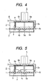
- Fig. 4 is a cross-sectional view illustrating a main part of a high frequency unit according to a second embodiment of the invention. Like elements corresponding to Fig. 2 are denoted by like reference numerals, so that a detailed description thereof is omitted.
- the second embodiment is significantly different from the above-mentioned first embodiment in that a linear leg portion 4b penetrating the circuit board 1 is provided to the side plate 4a extending from the peripheral portion of the mounting plate 4 to protrude, and the leg portion 4b is soldered to a ground circuit unit formed on a lower surface of the circuit board 1. Accordingly, the side plate 4a is retained by the circuit board 1 with the leg portion 4b interposed therebetween, so that the mounting plate 4 is hardly deformed.
- the side plate 4a of the mounting plate 4 is electrically connected to the ground circuit unit with the leg portion 4b of the mounting plate 4 interposed therebetween, and the shield effect on the core 5a can further be increased.
- Fig. 5 is a cross-sectional view illustrating a main part of a high frequency unit according to a third embodiment of the invention.
- Like elements corresponding to Figs. 2 and 4 are denoted by like reference numerals, so that a detailed description thereof is omitted.
- the third embodiment is different from the above-mentioned second embodiment in that an L-shaped leg portion 4c mounted on the circuit board 1 is provided to the side plate 4a extending from the peripheral portion of the mounting plate 4 to protrude, and the leg portion 4c is soldered to the ground circuit unit formed on an upper surface of the circuit board 1. Therefore, in the third embodiment, since the side plate 4a of the mounting plate 4 is retained by the circuit board 1 with the leg portion 4c interposed therebetween, the mounting plate 4 is hardly deformed. In addition, since the side plate 4a is electrically connected to the ground circuit unit with the leg portion 4c interposed therebetween, the shield effect on the core 5a can further be enhanced.
Landscapes
- Engineering & Computer Science (AREA)
- Microelectronics & Electronic Packaging (AREA)
- Shielding Devices Or Components To Electric Or Magnetic Fields (AREA)
- Coupling Device And Connection With Printed Circuit (AREA)
Abstract
Description
- The present invention contains subject matter related to Japanese Patent Application No.
2008-142782 - The present invention relates to a high frequency unit in which a coaxial connector is fixed to a mounting plate that is supported by side walls of a shield case enclosing a circuit board to face the circuit board, and the coaxial connector being attached to or detached from an external connector.
- In this type of high frequency unit, an outer edge of a mounting plate extending from side walls of a shield case along a circuit board is supported by the side walls or a partition wall, so that a coaxial connector fixed to the mounting plate is stably supported. The partition wall is a metal plate partitioning a space on the circuit board and fixed to the side walls of the shield case. In addition, a high frequency circuit unit such as a tuner circuit is formed on the circuit board, and a core extending from the coaxial connector toward the circuit board is soldered to a connection land of the high frequency circuit unit (for example, refer to Japanese Patent No.
4020743 - In a technique disclosed in Japanese Patent No.
4020743 - Besides, a high frequency unit having a configuration in which a coaxial connector is fixed to a mounting plate with a relatively smaller area has been widely used. In this configuration, an outer edge of the mounting plate is supported by one or two adjacent side walls of a shield case and a partition wall, and thus the mounting plate has a narrow width that is slightly greater than an outer diameter of the coaxial connector.
- In addition, an open end of the shield case at which the mounting plate is disposed is generally covered by a sheet metal cover provided with a through-hole through which a coaxial connector penetrates. The sheet metal cover covers the shield case while overlapping with the mounting plate and is fitted to the side walls of the shield case.
- However, in this type of high frequency unit, when an external connector is attached to or detached from the coaxial connector fixed to the mounting plate, a relatively high bending stress is exerted on the mounting plate. In the technique disclosed in Japanese Patent No.
4020743 - In addition, in the case of the existing high frequency unit in which the outer edge of the mounting plate is supported by one or two adjacent side walls of the shield case and the partition wall, peripheral portions that are easily deformed exist at the outer edge of the mounting plate. Therefore, there was a concern that, when attaching or detaching the external connector, the mounting plate is deformed and the junction of the core of the coaxial connector and the circuit board may be broken down.
- It is desirable to provide a high frequency unit capable of suppressing deformation of a mounting plate which needs to be concerned when attaching or detaching an external connector, at low costs and high reliability of a connection between a core of a coaxial connector and a circuit board.
- According to an aspect of the invention, there is provided a high frequency unit including: a shield case having a frame shape enclosing a circuit board with a plurality of side walls; a partition wall for partitioning a space on the circuit board; a mounting plate made of a metal sheet supported by the partition wall and the side walls of the shield case; and a coaxial connector fixed to the mounting plate to protrude outward, wherein a core extending from the coaxial connector toward the circuit board is connected to a high frequency circuit unit of the circuit board, and a side plate extends from a peripheral portion, which is not supported by the side walls and the partition wall, of an outer edge of the mounting plate, to be bent toward the circuit board.
- In the high frequency unit having the above-mentioned configuration, the side plate extending from the peripheral portion, which is not supported by the side walls of the shield case and the partition wall, of the outer edge of the mounting plate, functions as a reinforcing rib, so that the coaxial connector can be fixed to the mounting plate which has a relatively smaller area and is hardly deformed. Accordingly, at low cost, it is possible to effectively suppress deformation of the mounting plate which needs to be concerned when attaching or detaching an external connector, and reliability of a connection between the core of the coaxial connector and the circuit board can be increased. Moreover, due to the side plate provided to the mounting plate, the core of the coaxial connector can be enclosed by the side plate, the side walls of the shield case, and the partition wall. Therefore, a shield effect on the core can be enhanced, and an RF signal is not easily influenced by noises.
- In the high frequency unit having the above-mentioned configuration, three peripheral portions of the rectangular mounting plate may be supported by the two adjacent side walls of the shield case and the partition wall, and the side plate may extend from the remaining one peripheral portion of the mounting plate. Therefore, mechanical strength of the mounting plate can be enhanced, and the mounting plate is hardly deformed, which is preferable.
- In addition, in the high frequency unit having the above-mentioned configuration, the side plate of the mounting plate may have a leg portion, and the leg portion may be soldered to a ground circuit unit of the circuit board. Accordingly, the side plate is retained by the circuit board with the leg portion interposed therebetween, so that the mounting plate is hardly deformed. In addition, the side plate is electrically connected to the ground circuit unit with the leg portion interposed therebetween, and a shield effect on the core can further be increased.
- In addition, in the high frequency unit having the above-mentioned configuration, a sheet metal cover which has a through-hole through which the coaxial connector penetrates, and overlaps with the mounting plate to cover an open end of the shield case may further be included, wherein the sheet metal cover is provided with a jetty portion extending from a periphery of the through-hole to be bent toward the mounting plate such that the jetty portion comes in pressing contact with the mounting plate Therefore, a risk that internal high frequency waves and harmonic waves thereof leak through the through-hole and may affect the coaxial connector is small, and mechanical strength of the sheet metal cover can be enhanced due to the jetty portion. In addition, the mounting plate is hardly deformed, which means that the jetty portion comes in pressing contact with the mounting plate by being taken into the mounting plate.
- In the high frequency unit according to the aspect of the invention, the side plate extending from the peripheral portion, which is not supported by the side walls of the shield case and the partition wall, of the outer edge of the mounting plate, functions as a reinforcing rib, so that the coaxial connector can be fixed to the mounting plate which has a relatively smaller area and is hardly deformed. Accordingly, at low cost, it is possible to effectively suppress deformation of the mounting plate which needs to be concerned when attaching or detaching an external connector, and reliability of a connection between the core of the coaxial connector and the circuit board can be increased. In addition, the core of the coaxial connector can be enclosed by the side plate of the mounting plate, the side walls of the shield case, and the partition wall. Therefore, a shield effect on the core can be enhanced, and an RF signal is not easily influenced by noises.
-
-
Fig. 1 is a plan view illustrating a main part of a high frequency unit according to a first embodiment of the invention, where a sheet metal cover is omitted. -
Fig. 2 is a cross-sectional view taken along line A-A ofFig. 1 . -
Fig. 3 is a cross-sectional view taken along line B-B ofFig. 1 . -
Fig. 4 is a cross-sectional view illustrating a main part of a high frequency unit according to a second embodiment of the invention. -
Fig. 5 is a cross-sectional view illustrating a main part of a high frequency unit according to a third embodiment of the invention. - Exemplary embodiments of the invention will be described with reference to the accompanying drawings.
Fig. 1 is a plan view illustrating a main part of a high frequency unit according to a first embodiment of the invention, where a sheet metal cover is omitted.Fig. 2 is a cross-sectional view taken along line A-A ofFig. 1. Fig. 3 is a cross-sectional view taken along line B-B ofFig. 1 . - The high frequency unit illustrated in
Figs. 1 to 3 , schematically includes acircuit board 1 on which a high frequency circuit unit such as a tuner circuit is formed, ashield case 2 having a frame shape enclosing thecircuit board 1 with fourside walls 2a (here, one of the side walls is not shown), apartition wall 3 for partitioning a space on thecircuit board 1, amounting plate 4 which faces thecircuit board 1 and of which an outer edge is supported by theside walls 2a or thepartition wall 3, acoaxial connector 5 fixed to themounting plate 4 to protrude outward, asheet metal cover 6 covering an upper open end of theshield case 2, and alower cover 7 covering a lower open end of theshield case 2. - The
shield case 2, thesheet metal cover 6, and thelower cover 7 are formed by pressing metal sheets, and constitute a housing almost completely covering thecircuit board 1. Thepartition wall 3 is a metal plate fixed to theshield case 2, and a plurality of thepartition walls 3 are provided on thecircuit board 1. - The
mounting plate 4 is a rectangular metal sheet extending from one of theside walls 2a of theshield case 2 along thecircuit board 1, and three peripheral portions of the outer edge thereof are supported by the twoadjacent side walls 2a and thepartition wall 3. In addition, aside plate 4a made of a metal piece bent toward thecircuit board 1 extends from the one remaining peripheral portion of themounting plate 4. - A
core 5a of thecoaxial connector 5 fixed to themounting plate 4 extends toward thecircuit board 1 to be soldered to a connection land of the high frequency circuit unit. In addition, an external conductor of thecoaxial connector 5 is soldered to themounting plate 4. An external connector not shown is mounted to thecoaxial connector 5. - The
sheet metal cover 6 is provided with a through-hole 6a through which thecoaxial connector 5 penetrates, ajetty portion 6b which extends from a periphery of the through-hole 6a to be bent toward themounting plate 4, and a plurality ofengagement protrusions 6c to be engaged with theside wall 2a of theshield case 2. Theengagement protrusion 6c is engaged with theside wall 2a such that thesheet metal cover 6 is fitted to theshield case 2, and the upper open end of theshield case 2 is covered by thesheet metal cover 6 overlapping with themounting plate 4. In addition, when thesheet metal cover 6 is fitted to theshield case 2 as described above, thejetty portion 6b comes in pressing contact with themounting plate 4. - In the high frequency unit according to this embodiment, of the outer edge (four sides) of the
rectangular mounting plate 4, the remaining peripheral portion which is not supported by the twoside walls 2a and thepartition wall 3 is provided with thebent side plate 4a, and theside plate 4a functions as a reinforcing rib, so that thecoaxial connector 5 can be fixed to themounting plate 4 which has a relatively smaller area and is hardly deformed. Accordingly, it is possible to effectively suppress deformation of themounting plate 4 which needs to be concerned when the external connector is attached to or detached from thecoaxial connector 5, and reliability of a connection between thecore 5a of thecoaxial connector 5 and the high frequency circuit unit of thecircuit board 1 can be increased. In addition, it is possible to easily form theside plate 4a at the peripheral portion of themounting plate 4 by pressing, so that there is no concern about an increase in manufacturing costs. Moreover, when theside plate 4a extends from the mountingplate 4 as described above, thecore 5a of thecoaxial connector 5 can be enclosed by theside plate 4a, the twoside walls 2a, and the partition wall 3a. Therefore, a shield effect on thecore 5a can be enhanced, and an RF signal is not easily influenced by noises. - In addition, in the high frequency unit according to this embodiment, the
jetty portion 6b extends from the periphery of the through-hole 6a of thesheet metal cover 6 covering the upper open end of theshield case 2, and thejetty portion 6b comes in pressing contact with the mountingplate 4. Therefore, a risk that internal high frequency waves and harmonic waves thereof leak through the through-hole 6a and may affect thecoaxial connector 5 is small, and mechanical strength of thesheet metal cover 6 can be enhanced due to thejetty portion 6b. In addition, as described above, the mountingplate 4 is hardly deformed, which means that thejetty portion 6b comes in pressing contact with the mountingplate 4 by being taken into the mountingplate 4. -
Fig. 4 is a cross-sectional view illustrating a main part of a high frequency unit according to a second embodiment of the invention. Like elements corresponding toFig. 2 are denoted by like reference numerals, so that a detailed description thereof is omitted. - The second embodiment is significantly different from the above-mentioned first embodiment in that a
linear leg portion 4b penetrating thecircuit board 1 is provided to theside plate 4a extending from the peripheral portion of the mountingplate 4 to protrude, and theleg portion 4b is soldered to a ground circuit unit formed on a lower surface of thecircuit board 1. Accordingly, theside plate 4a is retained by thecircuit board 1 with theleg portion 4b interposed therebetween, so that the mountingplate 4 is hardly deformed. In addition, theside plate 4a of the mountingplate 4 is electrically connected to the ground circuit unit with theleg portion 4b of the mountingplate 4 interposed therebetween, and the shield effect on thecore 5a can further be increased. -
Fig. 5 is a cross-sectional view illustrating a main part of a high frequency unit according to a third embodiment of the invention. Like elements corresponding toFigs. 2 and4 are denoted by like reference numerals, so that a detailed description thereof is omitted. - The third embodiment is different from the above-mentioned second embodiment in that an L-shaped
leg portion 4c mounted on thecircuit board 1 is provided to theside plate 4a extending from the peripheral portion of the mountingplate 4 to protrude, and theleg portion 4c is soldered to the ground circuit unit formed on an upper surface of thecircuit board 1. Therefore, in the third embodiment, since theside plate 4a of the mountingplate 4 is retained by thecircuit board 1 with theleg portion 4c interposed therebetween, the mountingplate 4 is hardly deformed. In addition, since theside plate 4a is electrically connected to the ground circuit unit with theleg portion 4c interposed therebetween, the shield effect on thecore 5a can further be enhanced. - It should be understood by those skilled in the art that various modifications, combinations, sub-combinations and alternations may occur depending on design requirements and other factors insofar as they are within the scope of the appended claims of the equivalents thereof.
Claims (4)
- A high frequency unit comprising:a shield case (2) having a frame shape enclosing a circuit board (1) with a plurality of side walls (2a);a partition wall (3) for partitioning a space on the circuit board (1);a mounting plate (4) made of a metal sheet supported by the partition wall (3) and the side walls (2a) of the shield case (2); anda coaxial connector (5) fixed to the mounting plate (4) to protrude outward,wherein a core (5a) extending from the coaxial connector (5) toward the circuit board (1) is connected to a high frequency circuit unit of the circuit board (1), and
a side plate (4a) extends from a peripheral portion, which is not supported by the side walls (2a) and the partition wall (3), of an outer edge of the mounting plate (4), to be bent toward the circuit board (1). - The high frequency unit according to claim 1, wherein three peripheral portions of the rectangular mounting plate (4) are supported by the two adjacent side walls (2a) of the shield case (2) and the partition wall (3), and the side plate (4a) extends from the remaining one peripheral portion of the mounting plate (4).
- The high frequency unit according to claim 1 or 2,
wherein the side plate (4a) of the mounting plate (4) has a leg portion (4b,4c), and the leg portion (4b,4c) is soldered to a ground circuit unit of the circuit board (1). - The high frequency unit according to any one of claims 1 to 3, further comprising a sheet metal cover (6) which has a through-hole (6a) through which the coaxial connector (5) penetrates, and overlaps with the mounting plate (4) to cover an open end of the shield case (2),
wherein the sheet metal cover (6) is provided with a jetty portion (6b) extending from a periphery of the through-hole (6a) to be bent toward the mounting plate (4) such that the jetty portion (6b) comes in pressing contact with the mounting plate (4).
Applications Claiming Priority (1)
| Application Number | Priority Date | Filing Date | Title |
|---|---|---|---|
| JP2008142782A JP2009290085A (en) | 2008-05-30 | 2008-05-30 | High-frequency unit |
Publications (2)
| Publication Number | Publication Date |
|---|---|
| EP2129206A2 true EP2129206A2 (en) | 2009-12-02 |
| EP2129206A3 EP2129206A3 (en) | 2010-09-01 |
Family
ID=41016923
Family Applications (1)
| Application Number | Title | Priority Date | Filing Date |
|---|---|---|---|
| EP09006974A Withdrawn EP2129206A3 (en) | 2008-05-30 | 2009-05-25 | High frequency unit |
Country Status (3)
| Country | Link |
|---|---|
| US (1) | US7749017B2 (en) |
| EP (1) | EP2129206A3 (en) |
| JP (1) | JP2009290085A (en) |
Families Citing this family (4)
| Publication number | Priority date | Publication date | Assignee | Title |
|---|---|---|---|---|
| JP2010200129A (en) | 2009-02-26 | 2010-09-09 | Hitachi Media Electoronics Co Ltd | Tuner |
| EP2526749B1 (en) | 2010-01-21 | 2020-05-06 | InterDigital Madison Patent Holdings | Rf interference suppressor |
| US9948039B2 (en) * | 2016-03-24 | 2018-04-17 | Thomson Licensing | Apparatus for a shielded F-connector |
| CN111373664B (en) * | 2017-11-28 | 2022-07-29 | 索尼半导体解决方案公司 | Tuner module and receiving apparatus |
Citations (2)
| Publication number | Priority date | Publication date | Assignee | Title |
|---|---|---|---|---|
| JPH0420743B2 (en) | 1986-03-07 | 1992-04-06 | Mazda Motor | |
| JP2008142782A (en) | 2006-12-06 | 2008-06-26 | Okamoto Machine Tool Works Ltd | Flattening device of hydrostatic bearing |
Family Cites Families (9)
| Publication number | Priority date | Publication date | Assignee | Title |
|---|---|---|---|---|
| DE2932015C2 (en) * | 1978-08-07 | 1983-12-29 | Mitsumi Electric Co., Ltd., Tokyo | Shielding device for high frequency circuits |
| JPS60106379U (en) * | 1983-12-26 | 1985-07-19 | アルプス電気株式会社 | case for electronic equipment |
| JP3362269B2 (en) * | 1994-07-20 | 2003-01-07 | マスプロ電工株式会社 | Electronic equipment circuit unit |
| TW443717U (en) * | 1996-06-28 | 2001-06-23 | Sharp Kk | Tuner structure and cable modem tuner using the same |
| JP3729708B2 (en) * | 2000-06-19 | 2005-12-21 | シャープ株式会社 | Electronics |
| JP2002271080A (en) * | 2001-03-09 | 2002-09-20 | Toshiba Corp | High frequency device |
| JP3926576B2 (en) * | 2001-03-22 | 2007-06-06 | アルプス電気株式会社 | Tuner |
| JP4020743B2 (en) * | 2002-10-08 | 2007-12-12 | シャープ株式会社 | Digital broadcast receiving unit |
| JP4703104B2 (en) * | 2003-06-06 | 2011-06-15 | 株式会社東芝 | Communication terminal device |
-
2008
- 2008-05-30 JP JP2008142782A patent/JP2009290085A/en active Pending
-
2009
- 2009-05-25 EP EP09006974A patent/EP2129206A3/en not_active Withdrawn
- 2009-05-27 US US12/472,658 patent/US7749017B2/en not_active Expired - Fee Related
Patent Citations (2)
| Publication number | Priority date | Publication date | Assignee | Title |
|---|---|---|---|---|
| JPH0420743B2 (en) | 1986-03-07 | 1992-04-06 | Mazda Motor | |
| JP2008142782A (en) | 2006-12-06 | 2008-06-26 | Okamoto Machine Tool Works Ltd | Flattening device of hydrostatic bearing |
Also Published As
| Publication number | Publication date |
|---|---|
| US20090298329A1 (en) | 2009-12-03 |
| US7749017B2 (en) | 2010-07-06 |
| EP2129206A3 (en) | 2010-09-01 |
| JP2009290085A (en) | 2009-12-10 |
Similar Documents
| Publication | Publication Date | Title |
|---|---|---|
| EP3937316B1 (en) | Shielded PCB-to-PCB connector | |
| US7815467B2 (en) | Connector device | |
| US7458822B2 (en) | Electrical connector and combination connector having the same | |
| JP5006140B2 (en) | Connector and connector unit | |
| US8172613B1 (en) | Coaxial cable end connector | |
| JP4301414B2 (en) | Circuit board electrical connector | |
| CN110088978B (en) | Resonator and communication device | |
| JP5835491B2 (en) | Coaxial connector | |
| JP2011258508A (en) | Connector | |
| US7749017B2 (en) | High frequency unit with improved mounting plate | |
| EP2712030A1 (en) | Electric connector for circuit board and electric connector assembly including the same | |
| JP2006165201A (en) | Circuit module device | |
| JP4890400B2 (en) | Electronic circuit module | |
| CN215647732U (en) | Electronic device | |
| CN1220418C (en) | Shielded enclosure | |
| CN218959382U (en) | Shielding cover and electronic equipment | |
| CN108513522B (en) | Assembly component and assembly method thereof | |
| JP2008130263A (en) | Electrical connector for flat cable | |
| CN210489982U (en) | An improved board connector | |
| JP4159488B2 (en) | Communication equipment | |
| JP2013211249A (en) | Shield plate and connector mounted with the shield plate | |
| US20100245248A1 (en) | Mouse | |
| JP2006286456A (en) | Flexible board connector | |
| US20110149531A1 (en) | Electronic apparatus | |
| JP4659625B2 (en) | Electronics |
Legal Events
| Date | Code | Title | Description |
|---|---|---|---|
| PUAI | Public reference made under article 153(3) epc to a published international application that has entered the european phase |
Free format text: ORIGINAL CODE: 0009012 |
|
| AK | Designated contracting states |
Kind code of ref document: A2 Designated state(s): AT BE BG CH CY CZ DE DK EE ES FI FR GB GR HR HU IE IS IT LI LT LU LV MC MK MT NL NO PL PT RO SE SI SK TR |
|
| PUAL | Search report despatched |
Free format text: ORIGINAL CODE: 0009013 |
|
| AK | Designated contracting states |
Kind code of ref document: A3 Designated state(s): AT BE BG CH CY CZ DE DK EE ES FI FR GB GR HR HU IE IS IT LI LT LU LV MC MK MT NL NO PL PT RO SE SI SK TR |
|
| AX | Request for extension of the european patent |
Extension state: AL BA RS |
|
| 17P | Request for examination filed |
Effective date: 20110216 |
|
| GRAP | Despatch of communication of intention to grant a patent |
Free format text: ORIGINAL CODE: EPIDOSNIGR1 |
|
| STAA | Information on the status of an ep patent application or granted ep patent |
Free format text: STATUS: THE APPLICATION IS DEEMED TO BE WITHDRAWN |
|
| 18D | Application deemed to be withdrawn |
Effective date: 20130515 |