EP2129175B1 - Verfahren zum Erkennen eines Funkzellenausfalls - Google Patents
Verfahren zum Erkennen eines Funkzellenausfalls Download PDFInfo
- Publication number
- EP2129175B1 EP2129175B1 EP08290491A EP08290491A EP2129175B1 EP 2129175 B1 EP2129175 B1 EP 2129175B1 EP 08290491 A EP08290491 A EP 08290491A EP 08290491 A EP08290491 A EP 08290491A EP 2129175 B1 EP2129175 B1 EP 2129175B1
- Authority
- EP
- European Patent Office
- Prior art keywords
- base station
- cell
- radio
- outage
- radio cell
- Prior art date
- Legal status (The legal status is an assumption and is not a legal conclusion. Google has not performed a legal analysis and makes no representation as to the accuracy of the status listed.)
- Not-in-force
Links
Images

Classifications
-
- H—ELECTRICITY
- H04—ELECTRIC COMMUNICATION TECHNIQUE
- H04W—WIRELESS COMMUNICATION NETWORKS
- H04W24/00—Supervisory, monitoring or testing arrangements
-
- H—ELECTRICITY
- H04—ELECTRIC COMMUNICATION TECHNIQUE
- H04W—WIRELESS COMMUNICATION NETWORKS
- H04W88/00—Devices specially adapted for wireless communication networks, e.g. terminals, base stations or access point devices
- H04W88/08—Access point devices
Definitions
- the present invention relates to a method of detecting an outage of a radio cell, and a base station to execute said method.
- LTE Long Term Evolution
- eNB E-UTRAN Node B
- RF radio frequency
- OMC Operations & Maintenance Centre
- US 6,438,374 presents a method for control message processing should one of the application processors (serving a cell base station) fail.
- UE mobile terminals
- UE user equipment
- the object of the present invention is achieved by a method of detecting an outage of a radio cell in a wireless telecommunication network comprising a plurality of radio cells and two or more base stations, each radio cell associated with a base station providing telecommunication service to at least one user terminal inside the radio cell, the method comprising: monitoring, by at least one of said base stations, call control messages associated with at least one of the user terminals; providing, from the monitored call control messages, one or more indications; comparing said one or more indications with respective references; if an indication differs from the respective reference in excess of a predefined threshold, generating a respective trigger event; and indicating, dependent on one or more of said respective trigger events, that one or more radio cells are affected by an outage.
- a base station for detecting an outage of a radio cell in a wireless telecommunication network comprising a plurality of radio cells, said base station, and one or more other base stations, each radio cell associated with a base station providing telecommunication service to at least one user terminal inside the radio cell, the base station comprising a control unit adapted to monitor call control messages associated with at least one of the user terminals; provide, from the monitored call control messages, one or more indications; compare said one or more indications with respective references; if an indication differs from the respective reference in excess of a predefined threshold, generate a respective trigger event; and indicate, dependent on one or more of said respective trigger events, that one or more radio cells are affected by an outage.
- a base station may serve one or more radio cells.
- a radio cell served by a base station is said to be associated with this base station. Every radio cell is associated with a base station.
- a user terminal located in a radio cell is provided with telecommunication service by the base station serving said radio cell. If the base station or a part of the base station (e.g. sector antenna) stops its service, e.g., due to a power outage, the radio cell associated with the base station or the part of the base station ceases to exist.
- the wireless telecommunication network comprises at least two radio cells and at least two base stations.
- a radio cell associated with a first base station may have one or more neighbouring radio cells associated with one or more second base stations.
- the second base stations are called neighbouring/surrounding base stations with respect to the first base station.
- the present invention allows a first base station neighbouring a second base station to detect an outage of a radio cell associated with the second base station and inform the OMC, possibly in addition to the second base station.
- a report of a cell outage towards the OMC is no longer dependent on the base station affected by the cell outage, only. Instead, also a base station neighbouring the affected base station may detect a cell outage of a radio cell associated with the affected base station and inform the OMC. This means that the detection of a cell outage is faster and more reliable.
- the OMC In case of a total outage of a base station, e.g., due to electrical power outage, the OMC is informed by neighbouring base stations.
- An automatic adjustment of base station parameters and configuration, e.g., the orientation of the antennas, can be initiated to enhance the coverage in case an outage was detected by neighbouring base stations.
- the present invention provides a better opportunity for the operator to maintain radio services in case of a cell outage, e.g., by a faster reaction time in advance of and instead of complaints of the subscribers.
- the present invention is particularly useful in case of normal or high traffic, e.g., during rush hour, In the case of "normal” or “high” traffic a cell outage of a neighbouring radio cell may be detected immediately by surrounding base stations if as sufficient large number of mobile terminals (UE) are affected. However, the present invention is also useful in the case of low traffic, e.g., during night.
- the at least one base station monitors call control messages of one or more of the following types: the random access attempts performed by the at least one user terminal; handover reports sent by the at least one user terminal.
- Call control messages comprise messages that are sent to control a telecommunication call, e.g., signalling data.
- a call control message comprises data that are not media data.
- Random Access attemps During normal operation, the UEs are performing a Random Access procedure based on:
- the UEs In the case of a cell outage the UEs will detect that the radio link is no longer available and will start the "radio link failure" procedure. In this case the UE will contact surrounding radio cells via the Random Access procedure. In 3GPP RAN2 it was decided that in LTE the UE in case of radio link failure will signal the old cell ID (i.e. the ID of cell affected by the outage) to the new radio cell, while for other radio access technologies the UE might not report the old cell ID.
- the old cell ID i.e. the ID of cell affected by the outage
- Handover During mobility the UEs are moving from one radio cell to other radio cells by means of handover, which follows a specified HO procedure. In case of a cell outage. HO from the outage radio cell to surrounding cells of the same or other base stations will no longer occur. Additionally, no UE will leave the currently still active radio cells into the outage radio cell anymore. Normally the UEs report an "addition event" as soon as a new radio cell is within the reachability of the UE. In case of a cell outage, no UE in the still active cells will report the addition event of the outage cell any longer.
- an analysis of the random access attempts (A), and the HO processes (E) is performed:
- An extended trigger "A” includes a specification of the affected radio cell, e.g., a cell ID. It is possible that the UEs which are located in a radio cell affected by an outage, in case of a radio link failure, signal the "old" cell ID, i.e., the cell ID of the radio cell affected by the outage, when the UEs send a Random Access message.
- the "old" cell ID may be included in a Random Access message.
- a base station receiving a Random Access message receives the "old" cell ID, too. If a base station notices a peak of Random Access attempts, the base station may deduce that a cell outage has occurred. If the Random Access messages associated with the Random Access attempts comprise the cell ID of the radio cell affected by the outage, the base station also knows in which radio cell the cell outage has occurred.
- one of said indications is provided by averaging the number of said random access attempts over a predefined time period.
- the base station extracts, from a monitored random access attempt message, a cell ID.
- Said cell ID is an identification of the radio cell the reporting user terminal has been associated with. It is possible that the user terminal is still associated with this radio cell but now wants to leave it, looking for another serving radio cell by means of performing a regular handover. It is also possible that the user terminal is no longer associated with this radio cell because of an outage of the radio cell. In this case, the user terminal looks for another serving radio cell as a substitute by means of performing a random access attempt towards another radio cell within the radio link failure procedure.
- the cell ID is used as one of the one or more indications.
- the base station performs said extractions of the cell IDs from the monitored random access attempt messages over a pre-defined time period.
- the base station generates a statistics of the reported cell IDs by counting how often each cell ID is reported in the monitored random access attempt messages. The number of times a cell ID has been reported in a pre-defined time period is called the frequency of the cell ID.
- the base station compares, for each of the reported cell IDs, the frequency of a reported cell ID with a respective reference, e.g., a cell ID frequency typical for the network when no radio cell outage has occurred, If the frequency of a reported cell ID differs from the respective reference in excess of a predefined threshold specific for the cell ID, the base station generates a respective trigger event.
- a respective reference e.g., a cell ID frequency typical for the network when no radio cell outage has occurred
- the base station provides one of said indications by analysing said handover reports over a predefined time period. If a radio cell is no longer reported in said handover reports over a predefined time period, the base station generates a respective trigger event.
- the base station analyses said handover reports. Based on this analysis, the base station generates a list of neighbouring radio cells neighbouring said base station, i.e., radio cells which are neighbouring one or more of the radio cells associated with said base station.
- the base station correlates two or more of said indications to identify the one or more radio cells affected by an outage.
- a correlation can be made between two or more indications gained from the same radio cell. It is also possible that a correlation is made between one or more indications gained from different radio cells.
- topological data is provided wherein said topological data specifies neighbouring radio cells of said plurality of radio cells and/or neighbouring base stations of the wireless telecommunication network.
- the topological data specifies neighbour relationships among the base stations, preferably also among the radio cells of the wireless telecommunication network.
- the neighbour relationships may be included in neighbourhood information. Neighbourhood information is basically required for radio resource management, for self-configuration and self-optimisation of radio access networks, e.g. for coverage optimisation and interference co-ordination.
- the (updated) neighbourhood relations may be stored in the base station node the new radio cell(s) belongs to or in the neighbouring base stations/radio cells or In OMC databases.
- said topological data is provided by the network operator. From said topological data a list is generated, the list specifying the base stations neighbouring the at least one base station. Preferably, the list also specifies the radio cells neighbouring the at least one radio cell associated with the at least one base station. Preferably, said list is generated by the at least one base station.
- the at least one base station monitors call control messages, and at least one of said neighbouring base stations neighbouring the at least one base station monitors call control messages.
- the at least one base station provides, from the monitored call control messages, at least one indication.
- the at least one neighbouring base station provides, from the monitored call control messages, at least one indication.
- the at least one base station compares the at least one indication provided by the at least one base station with respective references.
- the at least one neighbouring base station compares the at least one indication provided by the at least one neighbouring base station with respective references. If the at least one indication provided by the at least one base station differs from the respective reference in excess of a predefined threshold, the at least one base station generates a respective trigger event. If the at least one indication provided by the at least one neighbouring base station differs from the respective reference in excess of a predefined threshold, the at least one neighbouring base station generates a respective trigger event.
- the at least one base station indicates, dependent on one or more of said respective trigger events, that one or more radio cells are affected by an outage.
- the at least one neighbouring base station indicates, dependent on one or more of said respective trigger events, that one or more radio cells are affected by an outage.
- the at least one base station correlates said at least one indication provided by the at least one base station and said at least one indication provided by the at least one neighbouring base station, preferably in combination with said topological data, for identification of the one or more radio cells affected by an outage.
- said topological data is provided by the network operator. From said topological data a list is generated, the list specifying the base stations neighbouring the at least one base station. Preferably, the list also specifies the radio cells neighbouring the at least one radio cell associated with the at least one base station. Preferably, said list is generated by the at least one base station.
- An advantage of this aforementioned preferred embodiment is that the information gathered by at least two different base stations is merged in the OMC or by communication among the base stations so that a better localisation of the radio cell affected by the outage is possible.
- the at least one base station receives said at least one indication provided by the at least one neighbouring base station via a communication connection between the at least one base station and the at least one neighbouring base station, e.g., a wire-line connection.
- a communication connection between the at least one base station and the at least one neighbouring base station, e.g., a wire-line connection.
- a deviation of the statistics of internal and external (UE information) values available in the base stations is used for the detection of a cell outage. From this deviation a base station can either deduce an enlargement of the size of one of its radio cells, or a rearrangement of its border towards other cells. In the first case, the base station can deduce that one of its neighbouring cells is in outage, although the base station does not know which of its neighbouring radio cells. In the second case, the base station can deduce that a certain neighbouring radio cell is in outage, i.e. the base station is able to identify the neighbouring radio cell in outage.
- Convenient internal and external UE information values are:
- an analysis of the CQI values (B), the TA values (C), and the power headroom values (D) is performed:
- At least one of said indications is provided by averaging the determined values of one of said RF-signal related parameters over a predefined time period.
- a base station provides one of said indications by averaging the determined values of one of said RF-signal related parameters over a predefined time period.
- the predefined time period may be chosen from about several hundred milliseconds to several minutes.
- a report is sent from the at least one base station to the OMC, Said report indicates that one or more neighbouring radio cells neighbouring the at least one radio cell associated with the at least one base station are affected by an outage.
- the use of the call control messages and the RF-signal related parameters for detecting an outage of a radio cell makes use of the following relationships. Shortly after a cell outage, the random access attempts per time reach a peak in the radio cells surrounding/neighbouring the affected radio cell. In case of an outage of a radio cell, the channel quality information CQI decreases for UEs previously located in the affected radio cell, and increases for UEs in a neighbouring radio cell. In case of an outage of a radio cell, the timing advance TA must be increased (by the base station serving these UEs) for UEs previously located in the affected radio cell. With regard to the power headroom, the percentage of UEs with low power headroom is increased in case of an outage of a radio cell. The handover pattern in an affected radio cell and in its neighbouring radio cells changes in case of an outage of a radio cell.
- the decision that a cell outage in a radio cell has occurred can either be based on trigger values B and/or C and/or D, or a combination of the trigger values B to D. In this case only a report of a cell outage without detailed information about the cell ID can be generated towards the OMC.
- the decision that a cell outage in a radio cell has occurred can either be based on trigger value A, with the supporting triggers B and/or C and/or D, or a combination of the trigger values A to D. In this case only a report of a cell outage without detailed information about the cell ID may be generated towards the OMC.
- the affected radio cell With the extended trigger A and/or the trigger E, the affected radio cell can be identified and a report containing, e.g., the cell ID of the affected radio cell can be generated and sent to the OMC.
- a combination of trigger E together with A and/or B and/or C or a combination of the trigger values A to E may initiate a generation of the message to the OMC
- the mean number of Random Access attempts per interval (trigger A), and the triggers B, C, D may be based on mean values defined on, e.g., daily basis or on configurable intervals (e.g. 07:00h to 08:00h, 08:00h to 9:00h, etc.).
- the base station analysing the more RF-signal related parameters and/or the call control messages may use mathematical algorithms specific for analysing and correlating the statistical behaviour.
- the application of the algorithm may result in a correlation coefficient which is a measure for a similarity of two data sets.
- a report is sent from the at least one base station to the OMC.
- Said report indicates that one or more radio cells are affected by an outage. It is possible that said report indicates that one or more neighbouring radio cells neighbouring the at least one radio cell associated with the at least one base station are affected by an outage.
- the control unit of the base station generates the report, and the report is sent from the at least one base station to the OMC. By means of sending a report, a communication between a base station and the OMC is enabled.
- a report is sent from the at least one base station to at least one other base station.
- Said report indicates that one or more radio cells are affected by an outage. It is possible that the report indicates that one or more neighbouring radio cells neighbouring the at least one radio cell associated with the at least one base station are affected by an outage.
- the control unit of the base station generates the report, and the report is sent from the at least one base station to at least one other base station. By means of sending a report, a communication among base stations is enabled.
- the step of indicating, dependent on one or more of said respective trigger events, that one or more radio cells are affected by an outage comprises sending a report from the at least one base station to the OMC and/or to at least one other base station.
- the report with the cell ID of the affected radio cell will be sent to other surrounding cells.
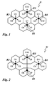
- Fig. 1 shows a wireless telecommunication network N, e.g., a UMTS LTE network, comprising four base stations B1 to B4.
- the base stations B1 to B4 may be a LTE eNB.
- Each of the base stations B1 to B4 has three antennas. Each of these antennas covers a respective sector forming one of the radio cells C1 to C12.
- the three antennas of base station B1 serve the three radio cells C1, C6, and C7.
- the three antennas of base station B2 serve the three radio cells C2, C8, and C9.
- the three antennas of base station B3 serve the three radio cells C3, C5. and C10.
- the three antennas of base station B4 serve the three radio cells C4, C11, and C12.
- Users with user terminals may move around in the wireless telecommunication network N.
- a user terminal located in the area of a radio cell is served by the associated base station.
- a user terminal located in the area of the radio cell C1 will be served by the upper antenna of base station B1.
- the radio cell C1 ceases to exist.
- the user terminals located in the area of the former radio cell C1 have to be served by radio cells neighbouring the former radio cell C1. Accordingly, the areas of the radio cells C2 to C7 neighbouring the former radio cell C 1 increase.
- Fig. 2 shows a state of the wireless telecommunication network N when the radio cells C2 to C7 have segmented the area of the former radio cell C1 among them.
- Fig. 3 shows the base station B2 and its associated, extended radio cell C2 after a part of the area of the affected radio cell C1 has been integrated into the radio cell C2.
- the area of the extended radio cell C2 shown in Fig. 3 corresponds to the area of the radio cell C2 shown in Fig. 2 .
- the extended radio cell C2 comprises an original area 20 and an additional area 21.
- the original area 20 - and the additional area 21 - may dynamically change (increase or decrease), e.g., dependent on the workload of its associated base station or the workload of neighbouring base stations.
- the original area 20 corresponds to the area of the radio cell C2 shown in Fig. 1 .
- the additional area 21 is a part of the area of the former radio cell C1.
- the additional area 21 may consist from one or more parts of one or more other cells.
- the base station B2 is composed of one or several inter-linked computers, i.e., a hardware platform, a software platform basing on the hardware platform and several application programs executed by the system platform formed by the software and hardware platform.
- the functionality of the base station B2 are provided by the execution of these application programs.
- the application programs or a selected part of these application programs constitute a computer software product providing a call control service as described in the following, when executed on the system platform. Further, such computer software product is constituted by a storage medium storing these application programs or said selected part of application programs.
- the base station B2 provides telecommunication service to a plurality of user terminals inside the radio cell C2. For sake of clarity only two user terminals UE1, UE2 are shown in Fig. 3 .
- a first user terminal UE1 is located in the original area 20, and a second user terminal UE2 is located in the additional area 21.
- the first user terminal UE1 exchanges data information with the base station B2 via a radio air interface downlink connection DL1 and an uplink connection UL1.
- the second user terminal UE2 exchanges data information with the base station B2 via a radio air interface downlink connection DL2 and an uplink connection UL2.
- the first user terminal UE1 and the second user terminal UE2 are moving between neighbouring radio cells.
- the user terminals UE1, UE2 perform a handover procedure and send UE handover reports towards the base station B2 of the source radio cell C2.
- these handover reports include the cell ID of the target radio cell.
- the affected radio cell is no longer reported by the UEs UE1.
- UE2 as possible handover targets, while other radio cells are still reported as possible handover targets.
- the base station B2 generates - according to the 3GPP handover procedure - a list of "foreign" surrounding radio cells surrounding the radio cell C2.
- the term “foreign” is meant to denote that the neighbouring radio cells C1, C3, C6 are not associated with the base station B2 detecting the outage.
- the list comprises the radio cells C1, C3, C6. It is also possible that the base station B2 receives this list of surrounding radio cells from a higher ranking entity of the network N, e.g.. from a network operator of the network N.
- the base station B2 monitors the handover reports from the two user terminals UE1, UE2 over a certain time interval.
- the control unit 33 provides, from the monitored handover messages of the two user terminals UE1, UE2, an indication. This indication may be, e.g., the cell IDs of the radio cells which are reported during the time interval.
- the control unit 33 compares said indication with a respective reference, e.g., the cell IDs of the radio cells that are on the list of the "foreign" surrounding radio cells surrounding the radio cell C2.
- the base station B2 detects a deviation of the list of reported handover targets from the list of all surrounding radio cells over a pre-defined time period, i.e., the base station B2 detects that the radio cell C1 has not been reported during the entire time period.
- the predefined threshold in the case of the handover reports may be set to zero: that means a deviation whatsoever results in the generation of a trigger event "E". If a radio cell is not reported over the pre-defined time period, the control unit 33 generates a respective trigger event "E" specific for the handover process. Triggered by the trigger "E", the control unit 33 generates a message to the OMC that the "foreign" neighbouring radio cell C1 neighbouring the radio cell C2 associated with the base station 82 is affected by an outage.
Landscapes
- Engineering & Computer Science (AREA)
- Computer Networks & Wireless Communication (AREA)
- Signal Processing (AREA)
- Mobile Radio Communication Systems (AREA)
- Investigating Or Analysing Biological Materials (AREA)
Claims (12)
- Ein Verfahren zum Erkennen eines Ausfalls einer Funkzelle (C1) in einem drahtlosen Telekommunikationsnetzwerk (N) mit einer Mehrzahl von Funkzellen (C1 bis C12) und zwei oder mehreren Basisstation(en) (B1 bis B4), wobei jede Funkzelle (C1 bis C12), die mit einer Basisstation (B1 bis B4) assoziiert ist, einen Telekommunikationsdienst an mindestens ein Benutzerendgerät (UE1, UE2) innerhalb der Funkzelle (C1 bis C12) bereitstellt, wobei das Verfahren umfasst:Überwachen, durch mindestens eine der besagten Basisstationen (B1 bis B4), von Rufsteuerungsnachrichten, welche mit mindestens einem der Benutzerendgeräte (UE1, UE2) assoziiert sind;Bereitstellen, aus den überwachten Rufsteuerungsnachrichten, einer oder mehrerer Angabe(n);Vergleichen der besagten einen oder mehreren Angabe(n) mit entsprechenden Referenzen;wenn eine Angabe von der entsprechenden Referenz über einen vorgegebenen Grenzwert hinaus abweicht, Erzeugen eines entsprechenden Triggerereignisses; undAnzeigen, in Abhängigkeit von einem oder mehreren der besagten entsprechenden Triggerereignisse, dass eine oder mehrere Funkzelle(n) (C1) von einem Ausfall betroffen ist/sind.
- Das Verfahren nach Anspruch 1,
dadurch gekennzeichnet,
dass das Verfahren weiterhin umfasst:Überwachen, durch die mindestens eine Basisstation (B1 bis B4), von Rufsteuerungsnachrichten eines oder mehrerer der folgenden Typen:• Ein wahlfreier Zugriffsversuch, durchgeführt von dem mindestens einen Benutzerendgerät (UE1, UE2);• eine Handover-Meldung, gesendet von dem mindestens einen Benutzerendgerät (UE1, UE2). - Das Verfahren nach Anspruch 2,
dadurch gekennzeichnet,
dass das Verfahren weiterhin umfasst:Mitteln der Anzahl der besagten wahlfreien Zugriffsversuche über eine vorgegebene Zeitspanne; undBereitstellen der besagten gemittelten Anzahl als eine der besagten Angaben. - Das Verfahren nach Anspruch 2,
dadurch gekennzeichnet,
dass das Verfahren weiterhin umfasst:Extrahieren, aus einer überwachten Nachricht über einen wahlfreien Zugriffsversuch, einer Zellen-ID als eine der einen oder mehreren Angaben, wobei die besagte Zellen-ID die Funkzelle, mit welcher das Benutzerendgerät (UE1, UE2), welches die Nachricht über den wahlfreien Zugriffsversuch sendet, assoziiert worden ist, anzeigt;Durchführen der besagten Extrahierung über eine vorgegebene Zeitspanne, und Erzeugen einer Statistik der angezeigten Zellen-IDs;Vergleichen, für eine jede der angezeigten Zellen-IDs, der Frequenz einer angezeigten Zellen-ID mit einer entsprechenden Referenz; undwenn die Frequenz einer angezeigten Zellen-ID über einen entsprechenden vorgegebenen Grenzwert hinaus von der entsprechenden Referenz abweicht, Erzeugen eines entsprechenden Triggerereignisses. - Das Verfahren nach Anspruch 2,
dadurch gekennzeichnet,
dass das Verfahren weiterhin umfasst:Bereitstellen der besagten Angaben durch Analysieren der besagten Handover-Meldungen über eine vorgegebene Zeitspanne; undwenn eine Funkzelle (C1) über eine vorgegebene Zeitspanne nicht mehr in den besagten Handover-Meldungen angezeigt wird, Erzeugen eines entsprechenden Triggerereignisses. - Das Verfahren nach Anspruch 5,
dadurch gekennzeichnet,
dass das Verfahren weiterhin umfasst:Erzeugen, auf der Basis der besagten Handover-Meldungen, einer Liste von benachbarten Funkzellen, welche mit der besagten mindestens einen Basisstation (B1 bis B4) benachbart sind. - Das Verfahren nach Anspruch 1,
dadurch gekennzeichnet,
dass das Verfahren weiterhin umfasst:Korrelieren von zwei oder mehr Angaben, um die eine oder mehreren von einem Ausfall betroffene(n) Funkzelle(n) zu identifizieren. - Das Verfahren nach Anspruch 1,
dadurch gekennzeichnet,
dass das Verfahren weiterhin umfasst:Bestimmen, durch die mindestens eine Basisstation (B1 bis B4), für mindestens eine der mit der mindestens einen Basisstation (B1 bis B4) assoziierten Funkzellen, von Werten eines oder mehrerer RF-signalbezogenen Parameter(s), welche(r) mit dem mindestens einen Benutzerendgerät (UE1, UE2) innerhalb der mindestens einen Funkzelle assoziiert ist/sind; undBereitstellen, aus den bestimmten Werten des einen oder mehrerer der RF-signalbezogenen Parameter, einer oder mehrerer Angabe(n), welche dem einen oder mehreren RF-signalbezogenen Parameter(n) entsprichtlentsprechen. - Das Verfahren nach Anspruch 8,
dadurch gekennzeichnet,
dass das Verfahren weiterhin umfasst:Bestimmen, durch die mindestens eine Basisstation (B1 bis B4), für die mindestens eine mit der mindestens einen Basisstation (81 bis 84) assoziierte Funkzelle, von Werten eines oder mehrerer der folgenden RF-signalbezogenen Parameter:• der Kanalqualitätsindikator, welcher von dem mindestens einen Benutzerendgerät (UE1, UE2) innerhalb der mindestens einen Funkzelle angezeigt wird;• die Zeitvorverlegung, welche dem mindestens einen Benutzerendgerät (UE1, UE2) innerhalb der mindestens einen Funkzelle zugewiesen wird;• die verfügbare Sendeleistungsdifferenz, welche von dem mindestens einen Benutzerendgerät (UE1, UE2) innerhalb der mindestens einen Funkzelle signalisiert wird. - Das Verfahren nach Anspruch 1,
dadurch gekennzeichnet,
dass das Verfahren weiterhin die folgenden Schritte umfasst:Senden einer Meldung an eine OMC, dass eine oder mehrere benachbarte Funkzelle(n), welche mit der mindestens einen mit der mindestens einen Basisstation assoziierten Funkzelle benachbart ist/sind, von einem Ausfall betroffen ist/sind. - Das Verfahren nach Anspruch 1,
dadurch gekennzeichnet,
dass das Verfahren weiterhin die folgenden Schritte umfasst:Senden einer Meldung an die mindestens eine andere Basisstation, dass eine oder mehrere benachbarte Funkzelle(n), welche mit der mindestens einen mit der mindestens einen Basisstation assoziierten Funkzelle benachbart ist/sind, von einem Ausfall betroffen ist/sind. - Eine Basisstation (B1 bis B4) zum Erkennen eines Ausfalls einer Funkzelle (C1) in einem drahtlosen Telekommunikationsnetzwerk (N) mit einer Mehrzahl von Funkzellen (C1 bis C12), der besagten Basisstation (B1 bis B4) und einer oder mehreren anderen Basisstation(en) (B1 bis B4), wobei jede Funkzelle (C1 bis C12), die mit einer Basisstation (B1 bis B4) assoziiert ist, einen Telekommunikationsdienst an mindestens ein Benutzerendgerät (UE1, UE2) innerhalb der Funkzelle (C1 bis C12) bereitstellt, wobei die Basisstation eine Steuereinheit umfasst, welche dazu ausgelegt ist, mit mindestens einem der Benutzerendgeräte (UE1, UE2) assoziierte Rufsteuerungsnachrichten zu überwachen; aus den überwachten Rufsteuerungsnachrichten eine oder mehrere Angabe(n) bereitzustellen; die besagte(n) eine oder mehreren Angabe(n) mit entsprechenden Referenzen zu vergleichen; wenn eine Angabe von der entsprechenden Referenz über einen vorgegebenen Grenzwert hinaus abweicht, ein entsprechendes Triggerereignis zu erzeugen; und in Abhängigkeit von einem oder mehreren der besagten Triggerereignisse anzuzeigen, dass eine oder mehrere Funkzelle(n) (C1) von einem Ausfall betroffen ist/sind.
Priority Applications (3)
| Application Number | Priority Date | Filing Date | Title |
|---|---|---|---|
| EP08290491A EP2129175B1 (de) | 2008-05-28 | 2008-05-28 | Verfahren zum Erkennen eines Funkzellenausfalls |
| AT08290491T ATE492999T1 (de) | 2008-05-28 | 2008-05-28 | Verfahren zum erkennen eines funkzellenausfalls |
| DE602008004115T DE602008004115D1 (de) | 2008-05-28 | 2008-05-28 | Verfahren zum Erkennen eines Funkzellenausfalls |
Applications Claiming Priority (1)
| Application Number | Priority Date | Filing Date | Title |
|---|---|---|---|
| EP08290491A EP2129175B1 (de) | 2008-05-28 | 2008-05-28 | Verfahren zum Erkennen eines Funkzellenausfalls |
Publications (2)
| Publication Number | Publication Date |
|---|---|
| EP2129175A1 EP2129175A1 (de) | 2009-12-02 |
| EP2129175B1 true EP2129175B1 (de) | 2010-12-22 |
Family
ID=39951651
Family Applications (1)
| Application Number | Title | Priority Date | Filing Date |
|---|---|---|---|
| EP08290491A Not-in-force EP2129175B1 (de) | 2008-05-28 | 2008-05-28 | Verfahren zum Erkennen eines Funkzellenausfalls |
Country Status (3)
| Country | Link |
|---|---|
| EP (1) | EP2129175B1 (de) |
| AT (1) | ATE492999T1 (de) |
| DE (1) | DE602008004115D1 (de) |
Cited By (6)
| Publication number | Priority date | Publication date | Assignee | Title |
|---|---|---|---|---|
| US8509762B2 (en) | 2011-05-20 | 2013-08-13 | ReVerb Networks, Inc. | Methods and apparatus for underperforming cell detection and recovery in a wireless network |
| US8665835B2 (en) | 2009-10-16 | 2014-03-04 | Reverb Networks | Self-optimizing wireless network |
| US9008722B2 (en) | 2012-02-17 | 2015-04-14 | ReVerb Networks, Inc. | Methods and apparatus for coordination in multi-mode networks |
| US9113353B1 (en) | 2015-02-27 | 2015-08-18 | ReVerb Networks, Inc. | Methods and apparatus for improving coverage and capacity in a wireless network |
| US9258719B2 (en) | 2011-11-08 | 2016-02-09 | Viavi Solutions Inc. | Methods and apparatus for partitioning wireless network cells into time-based clusters |
| US9369886B2 (en) | 2011-09-09 | 2016-06-14 | Viavi Solutions Inc. | Methods and apparatus for implementing a self optimizing-organizing network manager |
Families Citing this family (6)
| Publication number | Priority date | Publication date | Assignee | Title |
|---|---|---|---|---|
| US8498207B2 (en) | 2008-06-26 | 2013-07-30 | Reverb Networks | Dynamic load balancing |
| US9826416B2 (en) | 2009-10-16 | 2017-11-21 | Viavi Solutions, Inc. | Self-optimizing wireless network |
| US8385900B2 (en) | 2009-12-09 | 2013-02-26 | Reverb Networks | Self-optimizing networks for fixed wireless access |
| US10225752B2 (en) * | 2014-10-28 | 2019-03-05 | Telefonaktiebolaget Lm Ericsson (Publ) | First network node, method therein, computer program and computer-readable medium comprising the computer program for detecting outage of a radio cell |
| US11323958B2 (en) | 2016-03-22 | 2022-05-03 | British Telecommunications Public Limited Company | Transmitter outage reporting |
| GB2548805B (en) * | 2016-03-22 | 2020-02-19 | British Telecomm | Transmitter outage detection |
Family Cites Families (2)
| Publication number | Priority date | Publication date | Assignee | Title |
|---|---|---|---|---|
| US6862447B1 (en) * | 1999-02-16 | 2005-03-01 | Lucent Technologies Inc. | Method of making downlink operational measurements in a wireless communication system |
| US6438374B1 (en) * | 1999-05-26 | 2002-08-20 | Lucent Technologies Inc. | Dynamic multi-step overload control for message processing in wireless communication service network |
-
2008
- 2008-05-28 AT AT08290491T patent/ATE492999T1/de not_active IP Right Cessation
- 2008-05-28 EP EP08290491A patent/EP2129175B1/de not_active Not-in-force
- 2008-05-28 DE DE602008004115T patent/DE602008004115D1/de active Active
Cited By (8)
| Publication number | Priority date | Publication date | Assignee | Title |
|---|---|---|---|---|
| US8665835B2 (en) | 2009-10-16 | 2014-03-04 | Reverb Networks | Self-optimizing wireless network |
| US9226178B2 (en) | 2009-10-16 | 2015-12-29 | Reverb Networks | Self-optimizing wireless network |
| US8509762B2 (en) | 2011-05-20 | 2013-08-13 | ReVerb Networks, Inc. | Methods and apparatus for underperforming cell detection and recovery in a wireless network |
| US9369886B2 (en) | 2011-09-09 | 2016-06-14 | Viavi Solutions Inc. | Methods and apparatus for implementing a self optimizing-organizing network manager |
| US9258719B2 (en) | 2011-11-08 | 2016-02-09 | Viavi Solutions Inc. | Methods and apparatus for partitioning wireless network cells into time-based clusters |
| US10003981B2 (en) | 2011-11-08 | 2018-06-19 | Viavi Solutions Inc. | Methods and apparatus for partitioning wireless network cells into time-based clusters |
| US9008722B2 (en) | 2012-02-17 | 2015-04-14 | ReVerb Networks, Inc. | Methods and apparatus for coordination in multi-mode networks |
| US9113353B1 (en) | 2015-02-27 | 2015-08-18 | ReVerb Networks, Inc. | Methods and apparatus for improving coverage and capacity in a wireless network |
Also Published As
| Publication number | Publication date |
|---|---|
| ATE492999T1 (de) | 2011-01-15 |
| EP2129175A1 (de) | 2009-12-02 |
| DE602008004115D1 (de) | 2011-02-03 |
Similar Documents
| Publication | Publication Date | Title |
|---|---|---|
| EP2129175B1 (de) | Verfahren zum Erkennen eines Funkzellenausfalls | |
| RU2470491C1 (ru) | Способ и устройство оповещения об информации для указания отказа переключения | |
| EP2591625B1 (de) | Verfahren und funkbasisstationen zur bestimmung des leistungsstatus einer zelle | |
| CN102308625B (zh) | 电信系统中的锚定载波选择技术 | |
| CN105517023B (zh) | 评估网络性能的方法和装置 | |
| EP2139278B1 (de) | Verfahren zum Erkennen eines Funkzellenausfalls | |
| JP2016509801A (ja) | ロング・ターム・エボリューション(lte)ネットワークの妨害器検出及び回避の方法 | |
| EP2509353B1 (de) | Verfahren und system zur verwaltung von nachbarzelleninformation | |
| KR20110020398A (ko) | 광대역 무선통신 시스템에서 핸드오버 최적화를 위한 장치 및 방법 | |
| EP2330850B1 (de) | Weiterleitungssteuerung | |
| US20130279357A1 (en) | Method and System for Implementing Drive Test | |
| EP2767118B1 (de) | Messkonfigurationskarte für messereignisberichterstattung in mobilfunknetzen | |
| CN102461242A (zh) | 在无线通信系统中发送测量报告的方法 | |
| KR20100104022A (ko) | 이동통신시스템에서 무선링크 실패로 인한 호 절단을 개선하기 위한 방법 및 시스템 | |
| JP2013522987A (ja) | 隣接セル情報の報告を実現する方法及びシステム | |
| US20100035654A1 (en) | Base station, user device, and tracking area setting method | |
| CN101932014A (zh) | 载波聚合中测量配置的处理方法 | |
| CN101938774A (zh) | 载波聚合中测量和上报的方法 | |
| US20060240829A1 (en) | Discovery of neighbour cell beacon frequencies in mobile networks | |
| US8504049B2 (en) | Mobile communication system, base station, access gateway, and tracking area setting method | |
| CN102045756A (zh) | 载波聚合中的测量方法及用户设备 | |
| US10880017B2 (en) | Detecting a pulsed signal | |
| US11716656B2 (en) | System and method for handover management in mobile networks | |
| CN106937338B (zh) | 链路重建方法和系统 | |
| US9918246B2 (en) | Enhancing the usage of resources related to the transmission of environment-related information between a user equipment and a mobile communication network |
Legal Events
| Date | Code | Title | Description |
|---|---|---|---|
| PUAI | Public reference made under article 153(3) epc to a published international application that has entered the european phase |
Free format text: ORIGINAL CODE: 0009012 |
|
| AK | Designated contracting states |
Kind code of ref document: A1 Designated state(s): AT BE BG CH CY CZ DE DK EE ES FI FR GB GR HR HU IE IS IT LI LT LU LV MC MT NL NO PL PT RO SE SI SK TR |
|
| AX | Request for extension of the european patent |
Extension state: AL BA MK RS |
|
| 17P | Request for examination filed |
Effective date: 20100527 |
|
| GRAP | Despatch of communication of intention to grant a patent |
Free format text: ORIGINAL CODE: EPIDOSNIGR1 |
|
| AKX | Designation fees paid |
Designated state(s): AT BE BG CH CY CZ DE DK EE ES FI FR GB GR HR HU IE IS IT LI LT LU LV MC MT NL NO PL PT RO SE SI SK TR |
|
| GRAS | Grant fee paid |
Free format text: ORIGINAL CODE: EPIDOSNIGR3 |
|
| RIN1 | Information on inventor provided before grant (corrected) |
Inventor name: KAMINSKI, STEPHEN Inventor name: BAKKER, HAJO Inventor name: WEBER, ANDREAS |
|
| GRAA | (expected) grant |
Free format text: ORIGINAL CODE: 0009210 |
|
| AK | Designated contracting states |
Kind code of ref document: B1 Designated state(s): AT BE BG CH CY CZ DE DK EE ES FI FR GB GR HR HU IE IS IT LI LT LU LV MC MT NL NO PL PT RO SE SI SK TR |
|
| REG | Reference to a national code |
Ref country code: GB Ref legal event code: FG4D |
|
| REG | Reference to a national code |
Ref country code: CH Ref legal event code: EP |
|
| REG | Reference to a national code |
Ref country code: IE Ref legal event code: FG4D |
|
| REF | Corresponds to: |
Ref document number: 602008004115 Country of ref document: DE Date of ref document: 20110203 Kind code of ref document: P |
|
| REG | Reference to a national code |
Ref country code: DE Ref legal event code: R096 Ref document number: 602008004115 Country of ref document: DE Effective date: 20110203 |
|
| REG | Reference to a national code |
Ref country code: NL Ref legal event code: VDEP Effective date: 20101222 |
|
| PG25 | Lapsed in a contracting state [announced via postgrant information from national office to epo] |
Ref country code: LT Free format text: LAPSE BECAUSE OF FAILURE TO SUBMIT A TRANSLATION OF THE DESCRIPTION OR TO PAY THE FEE WITHIN THE PRESCRIBED TIME-LIMIT Effective date: 20101222 |
|
| LTIE | Lt: invalidation of european patent or patent extension |
Effective date: 20101222 |
|
| PG25 | Lapsed in a contracting state [announced via postgrant information from national office to epo] |
Ref country code: FI Free format text: LAPSE BECAUSE OF FAILURE TO SUBMIT A TRANSLATION OF THE DESCRIPTION OR TO PAY THE FEE WITHIN THE PRESCRIBED TIME-LIMIT Effective date: 20101222 Ref country code: AT Free format text: LAPSE BECAUSE OF FAILURE TO SUBMIT A TRANSLATION OF THE DESCRIPTION OR TO PAY THE FEE WITHIN THE PRESCRIBED TIME-LIMIT Effective date: 20101222 Ref country code: SI Free format text: LAPSE BECAUSE OF FAILURE TO SUBMIT A TRANSLATION OF THE DESCRIPTION OR TO PAY THE FEE WITHIN THE PRESCRIBED TIME-LIMIT Effective date: 20101222 Ref country code: SE Free format text: LAPSE BECAUSE OF FAILURE TO SUBMIT A TRANSLATION OF THE DESCRIPTION OR TO PAY THE FEE WITHIN THE PRESCRIBED TIME-LIMIT Effective date: 20101222 Ref country code: HR Free format text: LAPSE BECAUSE OF FAILURE TO SUBMIT A TRANSLATION OF THE DESCRIPTION OR TO PAY THE FEE WITHIN THE PRESCRIBED TIME-LIMIT Effective date: 20101222 Ref country code: LV Free format text: LAPSE BECAUSE OF FAILURE TO SUBMIT A TRANSLATION OF THE DESCRIPTION OR TO PAY THE FEE WITHIN THE PRESCRIBED TIME-LIMIT Effective date: 20101222 Ref country code: CY Free format text: LAPSE BECAUSE OF FAILURE TO SUBMIT A TRANSLATION OF THE DESCRIPTION OR TO PAY THE FEE WITHIN THE PRESCRIBED TIME-LIMIT Effective date: 20101222 Ref country code: BG Free format text: LAPSE BECAUSE OF FAILURE TO SUBMIT A TRANSLATION OF THE DESCRIPTION OR TO PAY THE FEE WITHIN THE PRESCRIBED TIME-LIMIT Effective date: 20110322 |
|
| PG25 | Lapsed in a contracting state [announced via postgrant information from national office to epo] |
Ref country code: EE Free format text: LAPSE BECAUSE OF FAILURE TO SUBMIT A TRANSLATION OF THE DESCRIPTION OR TO PAY THE FEE WITHIN THE PRESCRIBED TIME-LIMIT Effective date: 20101222 Ref country code: PT Free format text: LAPSE BECAUSE OF FAILURE TO SUBMIT A TRANSLATION OF THE DESCRIPTION OR TO PAY THE FEE WITHIN THE PRESCRIBED TIME-LIMIT Effective date: 20110422 Ref country code: GR Free format text: LAPSE BECAUSE OF FAILURE TO SUBMIT A TRANSLATION OF THE DESCRIPTION OR TO PAY THE FEE WITHIN THE PRESCRIBED TIME-LIMIT Effective date: 20110323 Ref country code: BE Free format text: LAPSE BECAUSE OF FAILURE TO SUBMIT A TRANSLATION OF THE DESCRIPTION OR TO PAY THE FEE WITHIN THE PRESCRIBED TIME-LIMIT Effective date: 20101222 Ref country code: CZ Free format text: LAPSE BECAUSE OF FAILURE TO SUBMIT A TRANSLATION OF THE DESCRIPTION OR TO PAY THE FEE WITHIN THE PRESCRIBED TIME-LIMIT Effective date: 20101222 Ref country code: NO Free format text: LAPSE BECAUSE OF FAILURE TO SUBMIT A TRANSLATION OF THE DESCRIPTION OR TO PAY THE FEE WITHIN THE PRESCRIBED TIME-LIMIT Effective date: 20110322 Ref country code: ES Free format text: LAPSE BECAUSE OF FAILURE TO SUBMIT A TRANSLATION OF THE DESCRIPTION OR TO PAY THE FEE WITHIN THE PRESCRIBED TIME-LIMIT Effective date: 20110402 Ref country code: IS Free format text: LAPSE BECAUSE OF FAILURE TO SUBMIT A TRANSLATION OF THE DESCRIPTION OR TO PAY THE FEE WITHIN THE PRESCRIBED TIME-LIMIT Effective date: 20110422 |
|
| PG25 | Lapsed in a contracting state [announced via postgrant information from national office to epo] |
Ref country code: PL Free format text: LAPSE BECAUSE OF FAILURE TO SUBMIT A TRANSLATION OF THE DESCRIPTION OR TO PAY THE FEE WITHIN THE PRESCRIBED TIME-LIMIT Effective date: 20101222 Ref country code: RO Free format text: LAPSE BECAUSE OF FAILURE TO SUBMIT A TRANSLATION OF THE DESCRIPTION OR TO PAY THE FEE WITHIN THE PRESCRIBED TIME-LIMIT Effective date: 20101222 Ref country code: NL Free format text: LAPSE BECAUSE OF FAILURE TO SUBMIT A TRANSLATION OF THE DESCRIPTION OR TO PAY THE FEE WITHIN THE PRESCRIBED TIME-LIMIT Effective date: 20101222 Ref country code: SK Free format text: LAPSE BECAUSE OF FAILURE TO SUBMIT A TRANSLATION OF THE DESCRIPTION OR TO PAY THE FEE WITHIN THE PRESCRIBED TIME-LIMIT Effective date: 20101222 |
|
| PLBE | No opposition filed within time limit |
Free format text: ORIGINAL CODE: 0009261 |
|
| STAA | Information on the status of an ep patent application or granted ep patent |
Free format text: STATUS: NO OPPOSITION FILED WITHIN TIME LIMIT |
|
| PG25 | Lapsed in a contracting state [announced via postgrant information from national office to epo] |
Ref country code: DK Free format text: LAPSE BECAUSE OF FAILURE TO SUBMIT A TRANSLATION OF THE DESCRIPTION OR TO PAY THE FEE WITHIN THE PRESCRIBED TIME-LIMIT Effective date: 20101222 |
|
| 26N | No opposition filed |
Effective date: 20110923 |
|
| PG25 | Lapsed in a contracting state [announced via postgrant information from national office to epo] |
Ref country code: MC Free format text: LAPSE BECAUSE OF NON-PAYMENT OF DUE FEES Effective date: 20110531 Ref country code: IT Free format text: LAPSE BECAUSE OF FAILURE TO SUBMIT A TRANSLATION OF THE DESCRIPTION OR TO PAY THE FEE WITHIN THE PRESCRIBED TIME-LIMIT Effective date: 20101222 Ref country code: MT Free format text: LAPSE BECAUSE OF FAILURE TO SUBMIT A TRANSLATION OF THE DESCRIPTION OR TO PAY THE FEE WITHIN THE PRESCRIBED TIME-LIMIT Effective date: 20101222 |
|
| REG | Reference to a national code |
Ref country code: DE Ref legal event code: R097 Ref document number: 602008004115 Country of ref document: DE Effective date: 20110923 |
|
| REG | Reference to a national code |
Ref country code: CH Ref legal event code: PCOW Free format text: ALCATEL LUCENT;3, AVENUE OCTAVE GREARD;75007 PARIS (FR) Ref country code: IE Ref legal event code: MM4A |
|
| PG25 | Lapsed in a contracting state [announced via postgrant information from national office to epo] |
Ref country code: IE Free format text: LAPSE BECAUSE OF NON-PAYMENT OF DUE FEES Effective date: 20110528 |
|
| REG | Reference to a national code |
Ref country code: CH Ref legal event code: PL |
|
| PG25 | Lapsed in a contracting state [announced via postgrant information from national office to epo] |
Ref country code: CH Free format text: LAPSE BECAUSE OF NON-PAYMENT OF DUE FEES Effective date: 20120531 Ref country code: LI Free format text: LAPSE BECAUSE OF NON-PAYMENT OF DUE FEES Effective date: 20120531 |
|
| PG25 | Lapsed in a contracting state [announced via postgrant information from national office to epo] |
Ref country code: LU Free format text: LAPSE BECAUSE OF NON-PAYMENT OF DUE FEES Effective date: 20110528 |
|
| PG25 | Lapsed in a contracting state [announced via postgrant information from national office to epo] |
Ref country code: TR Free format text: LAPSE BECAUSE OF FAILURE TO SUBMIT A TRANSLATION OF THE DESCRIPTION OR TO PAY THE FEE WITHIN THE PRESCRIBED TIME-LIMIT Effective date: 20101222 |
|
| PG25 | Lapsed in a contracting state [announced via postgrant information from national office to epo] |
Ref country code: HU Free format text: LAPSE BECAUSE OF FAILURE TO SUBMIT A TRANSLATION OF THE DESCRIPTION OR TO PAY THE FEE WITHIN THE PRESCRIBED TIME-LIMIT Effective date: 20101222 |
|
| REG | Reference to a national code |
Ref country code: FR Ref legal event code: GC Effective date: 20131018 |
|
| REG | Reference to a national code |
Ref country code: FR Ref legal event code: RG Effective date: 20141016 |
|
| REG | Reference to a national code |
Ref country code: FR Ref legal event code: PLFP Year of fee payment: 8 |
|
| REG | Reference to a national code |
Ref country code: FR Ref legal event code: CA Effective date: 20150521 |
|
| REG | Reference to a national code |
Ref country code: FR Ref legal event code: CA Effective date: 20150521 |
|
| REG | Reference to a national code |
Ref country code: FR Ref legal event code: PLFP Year of fee payment: 9 |
|
| REG | Reference to a national code |
Ref country code: FR Ref legal event code: PLFP Year of fee payment: 10 |
|
| REG | Reference to a national code |
Ref country code: FR Ref legal event code: PLFP Year of fee payment: 11 |
|
| PGFP | Annual fee paid to national office [announced via postgrant information from national office to epo] |
Ref country code: FR Payment date: 20210412 Year of fee payment: 14 Ref country code: DE Payment date: 20210505 Year of fee payment: 14 |
|
| PGFP | Annual fee paid to national office [announced via postgrant information from national office to epo] |
Ref country code: GB Payment date: 20210505 Year of fee payment: 14 |
|
| REG | Reference to a national code |
Ref country code: DE Ref legal event code: R119 Ref document number: 602008004115 Country of ref document: DE |
|
| GBPC | Gb: european patent ceased through non-payment of renewal fee |
Effective date: 20220528 |
|
| PG25 | Lapsed in a contracting state [announced via postgrant information from national office to epo] |
Ref country code: FR Free format text: LAPSE BECAUSE OF NON-PAYMENT OF DUE FEES Effective date: 20220531 |
|
| PG25 | Lapsed in a contracting state [announced via postgrant information from national office to epo] |
Ref country code: GB Free format text: LAPSE BECAUSE OF NON-PAYMENT OF DUE FEES Effective date: 20220528 Ref country code: DE Free format text: LAPSE BECAUSE OF NON-PAYMENT OF DUE FEES Effective date: 20221201 |