EP2128044A1 - Modular lashing system for the securing of loading units, Method for securing loading units in closed containers - Google Patents
Modular lashing system for the securing of loading units, Method for securing loading units in closed containers Download PDFInfo
- Publication number
- EP2128044A1 EP2128044A1 EP09006674A EP09006674A EP2128044A1 EP 2128044 A1 EP2128044 A1 EP 2128044A1 EP 09006674 A EP09006674 A EP 09006674A EP 09006674 A EP09006674 A EP 09006674A EP 2128044 A1 EP2128044 A1 EP 2128044A1
- Authority
- EP
- European Patent Office
- Prior art keywords
- lashing
- container
- lashings
- lashing system
- horizontal
- Prior art date
- Legal status (The legal status is an assumption and is not a legal conclusion. Google has not performed a legal analysis and makes no representation as to the accuracy of the status listed.)
- Granted
Links
Images


Classifications
-
- B—PERFORMING OPERATIONS; TRANSPORTING
- B65—CONVEYING; PACKING; STORING; HANDLING THIN OR FILAMENTARY MATERIAL
- B65D—CONTAINERS FOR STORAGE OR TRANSPORT OF ARTICLES OR MATERIALS, e.g. BAGS, BARRELS, BOTTLES, BOXES, CANS, CARTONS, CRATES, DRUMS, JARS, TANKS, HOPPERS, FORWARDING CONTAINERS; ACCESSORIES, CLOSURES, OR FITTINGS THEREFOR; PACKAGING ELEMENTS; PACKAGES
- B65D90/00—Component parts, details or accessories for large containers
- B65D90/004—Contents retaining means
- B65D90/0053—Contents retaining means fixed on the side wall of the container
-
- B—PERFORMING OPERATIONS; TRANSPORTING
- B60—VEHICLES IN GENERAL
- B60P—VEHICLES ADAPTED FOR LOAD TRANSPORTATION OR TO TRANSPORT, TO CARRY, OR TO COMPRISE SPECIAL LOADS OR OBJECTS
- B60P7/00—Securing or covering of load on vehicles
- B60P7/06—Securing of load
- B60P7/08—Securing to the vehicle floor or sides
- B60P7/0823—Straps; Tighteners
-
- B—PERFORMING OPERATIONS; TRANSPORTING
- B63—SHIPS OR OTHER WATERBORNE VESSELS; RELATED EQUIPMENT
- B63B—SHIPS OR OTHER WATERBORNE VESSELS; EQUIPMENT FOR SHIPPING
- B63B25/00—Load-accommodating arrangements, e.g. stowing, trimming; Vessels characterised thereby
- B63B25/24—Means for preventing unwanted cargo movement, e.g. dunnage
-
- B—PERFORMING OPERATIONS; TRANSPORTING
- B65—CONVEYING; PACKING; STORING; HANDLING THIN OR FILAMENTARY MATERIAL
- B65D—CONTAINERS FOR STORAGE OR TRANSPORT OF ARTICLES OR MATERIALS, e.g. BAGS, BARRELS, BOTTLES, BOXES, CANS, CARTONS, CRATES, DRUMS, JARS, TANKS, HOPPERS, FORWARDING CONTAINERS; ACCESSORIES, CLOSURES, OR FITTINGS THEREFOR; PACKAGING ELEMENTS; PACKAGES
- B65D2590/00—Component parts, details or accessories for large containers
- B65D2590/0041—Contents retaining means
- B65D2590/005—Contents retaining means adaptable to the size of the transport goods
Abstract
Description
Die Erfindung betrifft ein Verzurrsystem zum Schrägverzurren von Ladeeinheiten in Containern mit Hilfe von Lashings (Verzurrbändern und/oder Gurten).The invention relates to a lashing system for schrägverzurren loading units in containers by means of lashings (lashing straps and / or straps).
Ladeeinheiten sind Verpackungen von festen, staubförmigen, gasförmigen oder flüssigen Gütern jeglicher Art oder diese Güter selbst. Ladeeinheiten können sowohl lose, z.B. als kleine Kartons oder Kunststoffbehälter, aber auch als Palettenware oder Kisten oder große Maschinenteile oder den Container komplett ausfüllende Kunststoffsäcke (Inliner) vorliegen.Loading units are packages of solid, dusty, gaseous or liquid goods of any kind or these goods themselves. Loading units can be both loose, e.g. as small boxes or plastic containers, but also as pallets or boxes or large machine parts or the container completely filling plastic bags (inliner) are present.
Um Container mit ungleichen Frachtgütern möglichst vollständig zu beladen, beschreibt die
Transportbedingte Belastungen durch Bewegungen von Transportgütern auf Lastkraftwagen, Flugzeugen, Bahn oder Schiff führen immer wieder zu hohen Schäden an Gütern, wenn diese nicht oder nicht ausreichend gesichert werden. Vielfach werden diese Container mit Gütern beladen und ohne Sicherung versandt.Transport-related loads due to movements of goods on trucks, airplanes, trains or ships repeatedly lead to high damage to goods if they are not or not adequately secured. In many cases, these containers are loaded with goods and shipped without security.
Vor allem die auf Übersee-Containern und damit auf die darin befindlichen Güter einwirkenden Transportbelastungen werden von den Beladenden vielfach unterschätzt. Von den Versicherern werden hohe Schadenssummen genannt, die jährlich auf Fehler im Bereich der Verladung und Ladungssicherung in Übersee-Containern zurückzuführen sind. Während fehlende oder fehlerhafte Ladungssicherung auf einem LKW bei extremen Fahrsituationen, wie zum Beispiel Notbremsung, eventuell durch den Fahrer entdeckt und nachgebessert werden kann, ist dies in einem Übersee-Container auf einem Containerschiff nicht möglich. Vom Zeitpunkt des Schließens der Containertür bis zum Öffnen der Tür am Zielort muss die Ladungssicherung also allen Transportbelastungen genügen.Above all, the transport loads acting on overseas containers and thus on the goods contained therein are often underestimated by the loaders. Insurers cite high levels of damage annually due to loading and oversight errors in overseas containers. While missing or faulty load securing on a truck in extreme driving situations, such as emergency braking, may be discovered and repaired by the driver, this is not possible in an overseas container on a container ship. From the time of closing the container door until the door is opened at the destination, the load securing must therefore meet all transport loads.
Übliche Sicherungen sind u.a. Holzkonstruktionen, Sperrstangen, Airbags, Netze, Folien und Verzurrbänder unterschiedlicher Konsistenz. Diese Materialien werden entsprechend der Ladungssicherungsaufgabe beim Verladevorgang vorbereitet und dann verarbeitet. Beispiele: Holzbalken werden an die Bedürfnisse der Aufgabe angepasst und in die Sicken der Container eingeschlagen. Airbags werden in Ladelücken positioniert und aufgeblasen. Netze werden montiert und gespannt, Ladeeinheiten mit Folien umhüllt und gesichert, Spanngurte und Bandmaterialien nach Bedarf auf Länge geschnitten, angebracht und verspannt.Typical fuses include wooden structures, barrier rods, airbags, nets, foils and lashing straps of varying consistency. These materials are prepared according to the load securing task during the loading process and then processed. Examples: be wooden beams adapted to the needs of the task and wrapped in the beads of the container. Airbags are positioned in cargo gaps and inflated. Nets are mounted and tensioned, loading units wrapped with films and secured, tension straps and tape materials cut to length as required, attached and braced.
Alle Ladungssicherungsmittel die im Container Verwendung finden, sind bis auf wenige Ausnahmen nur für diesen einen Transportvorgang im Einsatz. Eine Wiederverwendung der Mittel scheitert wegen hoher Rücktransportkosten, denn Container sind weltweit im Einsatz. Alle bekannten Hilfsmittel für die Ladungssicherung im Container sind deshalb Einwegsicherungen. Im Gegensatz zu Mehrweg-Produkten sollten diese deshalb kostengünstig sein, die ungleich schwierige Ladungssicherungsaufgabe im Container jedoch erfüllen und dann auch sicher und kostengünstig entsorgt werden können.All load securing devices that are used in the container are, with few exceptions, only for this one transport operation in use. A reuse of funds fails because of high return transport costs, because containers are in use worldwide. All known tools for load securing in the container are therefore disposable. In contrast to reusable products, these should therefore be cost-effective, but they must fulfill the unequal difficult load securing task in the container and then be safely and cost-effectively disposed of.
Es gibt keine technisch eindeutig begründbaren Vorgaben von Seiten der Behörden oder anderen branchenspezifischen Fachorganisationen, wie und mit welchen Mitteln Ladungssicherung im Übersee-Container auszuführen ist. Einige Publikationen erläutern" Empfehlungen" für Ladungssicherungstechniken, die sich in der Vergangenheit bewährt haben. Allen Empfehlungen ist gemein, dass rechnerische Nachweise der Ladungssicherungstechnik für zu sichernde Ladeeinheiten im Container nicht bekannt sind.There are no technically unambiguous requirements on the part of the authorities or other sector-specific specialist organizations, how and with what means load securing in the overseas container is to be carried out. Some publications explain "recommendations" for load securing techniques that have worked well in the past. All recommendations have in common that mathematical proofs of the load securing technology for securing load units in the container are not known.
Ziel jeder Ladungssicherung ist im Allgemeinen die Bildung von Gruppen oder Blöcken, die zusammengefasst eine Bewegung des Ladegutes verhindern sollen. Dies gelingt im Container nur schwer, weil Formschluss mit den geometrisch vorgegebenen Wänden des Containers nicht immer erzielt werden kann und damit Bewegungen einer ganzen Gruppe von Ladeeinheiten möglich sind. Zwar gibt es Ladungssicherungsmittel wie z. B. Airbags, mit denen Lücken im Container ausgefüllt werden können. Welche Ladungssicherungswirkung damit zu erzielen ist, kann rechnerisch jedoch nicht effektiv genug nachgewiesen werden.The aim of any load securing is generally the formation of groups or blocks, which should together prevent movement of the load. This is difficult to achieve in the container, because positive fit with the geometrically predetermined walls of the container can not always be achieved and thus movements of a whole group of loading units are possible. Although there are load securing means such. As airbags with which gaps in the container can be filled. However, which load-securing effect can be achieved can not be demonstrated with sufficient efficiency.
Auch bei der Verwendung von handelsüblichen Verzurrmaterialien sind rechnerische Nachweise über die Qualität der Ladungssicherung bezogen auf die zu sichernden Ladeeinheiten unter Einfluss des geometrischen Verlaufs der Verzurrung und unter Berücksichtigung der zulässigen Belastungen der Verzurrösen im Container nicht bekannt.Even with the use of commercially available lashing materials computational evidence on the quality of the load securing based on the load units to be secured under the influence of the geometric course of the lashing and taking into account the permissible loads of lashing eyes in the container are not known.
Bewegung der Ladeeinheiten im Container bedeuten während des Transports auf einem Containerschiff immer wiederkehrende Belastungen der Güter (dynamische Kraftwirkungen beim Stampfen und Rollen eines Container-Schiffs). Bewegungen der Ladeeinheiten während der Verladung der Container vom Pier in das Schiff bedeuten vielfach hohe Stoßbelastungen, die bis zu einem Mehrfachen des Gewichts der Güter reichen können.Movement of the loading units in the container mean during transport on a container ship recurring loads on the goods (dynamic force effects during pounding and rolling a container ship). Movements of the loading units during the loading of the containers from the pier into the ship often mean high impact loads, which can reach up to a multiple of the weight of the goods.
Ein Verzurrsystem muss in der Lage sein, die Ladeeinheiten im Container während des kompletten Transportverlaufs so zu sichern, dass entstehende Kraftwirkungen keine Schäden an der Ware, am Container und in der Umwelt verursachen können. Ein Verzurrsystem für Übersee-Container soll deshalb produktspezifisch bzw. dem Ladegut entsprechend angepasst werden können.A lashing system must be able to secure the load units in the container during the entire course of the transport so that the effects of force can not cause damage to the goods, the container and the environment. A lashing system for overseas containers should therefore be able to be adapted product-specifically or to the load accordingly.
Die Ladungssicherung auf Straßenfahrzeugen wird in DIN EN 12640 und in der FVDI Richtlinie VDI 2700 beschrieben. Die Ladungssicherung im Übersee-Container wird u.a. in der CTU Packrichtlinie des LIS der BAM und im Containerhandbuch des GDV beschrieben.Load securing on road vehicles is described in DIN EN 12640 and in the FVDI guideline VDI 2700. The load securing in the overseas container is u.a. in the CTU packing guideline of the LIS of the BAM and in the container manual of the GDV.
Es ist Aufgabe der vorliegenden Erfindung ein neues Verzurrsystem zur Sicherung von Ladungen in geschlossenen Ladungsträgern, wie beispielsweise Containern, zur Verfügung zu stellen, das die im Rahmen des Transportvorgangs auftretende Kräfte - im Rahmen einer überschaubaren plastischen und elastischen Verformung des Systems - ableiten kann.It is an object of the present invention to provide a new lashing system for securing loads in closed load carriers, such as containers, which can derive the forces occurring during the transport process - within the scope of a manageable plastic and elastic deformation of the system.
Es wurde ein Verzurrsystem zur Sicherung von Ladungen in Containern mit Hilfe von Lashings gefunden, das dadurch gekennzeichnet ist, dass die Ladung über schräg gespannte Lashings mit dem Container verbunden ist, wobei die Lashings durch senkrechte Abstandhalter fixiert werden, und das System modular aufgebaut ist.A lashing system was found for securing loads in containers with the help of lashings, which is characterized that the load is connected to the container via obliquely stretched lashings, whereby the lashings are fixed by vertical spacers, and the system has a modular structure.
Mit Hilfe des erfindungsgemäßen Verzurrsystems können die im Rahmen eines Transportvorgangs auftretenden Kräfte in mathematisch reproduzierbarer Weise an die starken Konstruktionsteile des Containers abgeleitet werden.With the help of the lashing system according to the invention, the forces occurring in the context of a transport process can be derived in a mathematically reproducible manner to the strong construction parts of the container.
Vorzugsweise handelt es sich bei den Containern um Transportvorrichtungen für Ladegut, bei denen die Ladung mittels Verzurrbändern in geeigneten Bereichen, beispielsweise am Boden, im oberen Rahmen oder an sonstigen starken Konstruktionsteilen des Containers befestigt werden kann. Bevorzugte Container können beispielsweise Transportvorrichtungen sein, bei denen die Verzurrbänder an Befestigungspunkten, z. B. an Ösen befestigt werden können und so das Ladegut sichern.The containers are preferably transport devices for load, in which the load can be fastened by means of lashing straps in suitable areas, for example on the floor, in the upper frame or on other strong construction parts of the container. Preferred containers may for example be transport devices in which the lashing straps at attachment points, for. B. can be attached to eyelets and secure the load.
Bevorzugte Container im Rahmen der vorliegenden Erfindung können Lastwagen, Container und Ladeflächen in Flugzeugen oder Schiffen sein.Preferred containers in the context of the present invention may be lorries, containers and loading areas in aircraft or ships.
Die Befestigungspunkte sind in der Regel symmetrisch im Container angebracht, so dass sich die auf die Ladung wirkenden Kräfte gleichmäßig verteilen. Zur Sicherung des Ladegutes sind in der Regel mindesten vier Befestigungspunkte pro Verzurrsystem erforderlich. Befestigungspunkte können beispielsweise Ösen sein. Eine aus der Praxis bekannte Art von Containern, die insbesondere zum Transport von in Kanistern, Fässern oder ähnlichen Behältnissen aufgenommenen chemischen Produkten dient, weist an den Seitenwänden des Containers nahe des Bodens und nahe der Decke jeweils eine Reihe von fünf Ösen in jeweils gleichen Abständen auf. Die Ösen sind dabei so angeordnet, dass sich jeweils paarweise an Boden und Decke des Containers Ösen gegenüberliegen. Diese Anordnung ermöglicht es auf einfache Weise, zwischen diesen sich paarweise gegenüberliegenden Ösen senkrechte Abstandshalter anzubringen.The attachment points are usually mounted symmetrically in the container, so that distribute the forces acting on the charge evenly. To secure the cargo usually at least four attachment points per lashing system are required. Attachment points can be eyelets, for example. A known from the field of containers, which is used in particular for the transport of chemical products contained in cans, barrels or similar containers, has on the side walls of the container near the bottom and near the ceiling each have a series of five eyelets at equal intervals , The eyelets are arranged so that in pairs opposite to the bottom and top of the container eyelets. This arrangement makes it easy to install vertical spacers between these pairs of opposed eyelets.
Die senkrechten Abstandshalter weisen vorzugsweise eine Mehrzahl von zueinander beanstandeten Öffnungen auf, die zur Aufnahme der Lashings dienen. Hierdurch wird es vorteilhaft möglich, auf flexible Weise Lashings in unterschiedlicher Höhe an den senkrechten Abstandshaltern zu befestigen. Somit kann eine Verzurrung von Ladeeinheiten in dem Container flexibel an die Geometrie der jeweiligen Ladungsanordnung angepasst werden.The vertical spacers preferably have a plurality of mutually spaced openings which serve to receive the lashings. This makes it advantageously possible to attach lashings in different heights to the vertical spacers in a flexible manner. Thus, a lashing of loading units in the container can be flexibly adapted to the geometry of the respective charge arrangement.
In einer bevorzugten Ausführungsform sind die senkrechten Abstandshalter dazu aus einem Gewebeband ausgebildet, das in regelmäßigen, relativ kleinen Abständen Öffnungen aufweist, durch welche Lashings hindurchgefädelt werden können. Zweckmäßig sind die Öffnungen dabei so ausgebildet, dass Fasern des Gewebebands nicht durch die Öffnungen aufgetrennt werden. Dies kann beispielsweise dadurch erreicht werden, dass die Öffnungen nicht nachträglich in ein fertiges Gewebeband beispielsweise durch Schneiden eingebracht werden, sondern dass bei der Erstellung des Gewebebands durch Aufteilung der Kettfäden in regelmäßigen Abständen Schlaufen in dem Gewebeband erzeugt werden. Durch diese Webtechnik können Öffnungen in dem Gewebeband erzeugt werden, die eine besonders hohe Festigkeit aufweisen. Ein Ausreißen der Öffnungen bei hoher Kraftbeanspruchung der Lashings kann dadurch vorteilhaft vermieden werden. Es versteht sich, dass die Öffnungen der senkrechten Abstandshalter jedoch auch durch Schneiden erzeugt werden können, wobei zusätzlich eine jeweilige Randverstärkung der entstandenen Öffnung vorgesehen sein kann. Dies ermöglicht eine kostengünstige Erstellung der senkrechten Abstandshalter. Alternativ können die Öffnungen auch Aufnähen weiterer Gewebeabschnitte oder das Vernähen zweier Gurtbänder parallel zueinander erzeugt werden. Es versteht sich weiter, dass die senkrechten Abstandshalter statt aus einem flexiblen Gewebeband auch aus einem starren Material, beispielsweise einem Metall, gefertigt sein können.In a preferred embodiment, the vertical spacers for this purpose are formed from a fabric band which has openings at regular, relatively small intervals, through which lashings can be threaded through. Suitably, the openings are formed so that fibers of the tissue band are not separated by the openings. This can be achieved, for example, that the openings are not subsequently introduced into a finished fabric tape, for example by cutting, but that are generated in the creation of the fabric tape by dividing the warp threads at regular intervals loops in the fabric tape. By this weaving technique openings can be produced in the fabric tape, which have a particularly high strength. A tearing of the openings under high load of the lashings can be advantageously avoided. It is understood, however, that the openings of the vertical spacers can also be produced by cutting, wherein in addition a respective edge reinforcement of the resulting opening can be provided. This allows a cost-effective creation of vertical spacers. Alternatively, the openings can also be produced by sewing on further fabric sections or sewing two belt straps parallel to one another. It is further understood that the vertical spacers instead of a flexible fabric tape can also be made of a rigid material, such as a metal.
Zweckmäßig ist die Länge der senkrechten Abstandshalter auf den Abstand zweier sich gegenüberliegender Befestigungspunkte abgestimmt. Eine Befestigung der senkrechten Abstandshalter an den Befestigungspunkten kann dabei vorzugsweise durch Haken, beispielsweise Karabinerhaken, an als Ösen ausgebildeten Befestigungspunkten erfolgen.Suitably, the length of the vertical spacer is matched to the distance between two opposing attachment points. A Attachment of the vertical spacers at the attachment points can preferably be effected by hooks, for example snap hooks, on attachment points designed as eyelets.
Als Ladung seien homogen und inhomogen gestapelte Bestandteile auch unterschiedlicher Zusammensetzung genannt. Bevorzugte Ladungen sind Fässer und Kisten unterschiedlicher Größe.As charge homogeneous and inhomogeneously stacked components are also called different composition. Preferred loads are barrels and boxes of different sizes.
Die als Lashings bezeichneten Haltegurte können aus Kunststoffasern und/oder Baumwolle sein. Es kommen hierbei handelsübliche und gegebenenfalls neu entwickelte Gurtbandqualitäten zum Einsatz. Insbesondere bei der Verwendung der Lashings in zum Hochseetransport bestimmten Containern ergeben sich hohe Anforderungen an die Festigkeit und die elastischen Eigenschaften der Lashings, da die typischen, sich in kurzen Zeitabständen wiederholenden Kraftbelastungen durch dauerhafte, plastische Verformung der Lashings zu einem Lockern der Verzurrung führen können. Entsprechend weisen die verwendeten Lashings vorzugsweise eine hohe Elastizität und eine nur sehr geringe oder gar keine plastische Verformbarkeit auf.The tethers called lashings can be made of synthetic fibers and / or cotton. Commercially available and possibly newly developed webbing qualities are used here. Particularly when using the lashings in containers intended for ocean transport, high demands are placed on the strength and the elastic properties of the lashings, since the typical, repeated at short intervals force loads by permanent plastic deformation of the lashings can lead to a loosening of the lashing. Accordingly, the lashings used preferably have a high elasticity and only very little or no plastic deformability.
Die Gurtbänder können in an sich bekannter Weise, z. B. durch Weben unter Verwendung von an sich bekannten Fasern und einer üblichen Nachbehandlung, beispielsweise durch Erhitzung, hergestellt werden.The straps can in a conventional manner, for. B. by weaving using fibers known per se and a conventional post-treatment, for example by heating, are produced.
In einer bevorzugten Anordnung zur Sicherung von Ladung in einem Container sind nahe der Ecken des Containers an den langen Seitenwänden jeweils senkrechte Abstandshalter angeordnet. Vorzugsweise werden die senkrechten Abstandshalter dabei jeweils zwischen sich gegenüberliegenden Befestigungspunkten nahe des Bodens und der Decke des Containers gespannt. Weiter werden etwa in der Mitte der Seitenwände nahe des Bodens oder der Decke des Containers Lashings befestigt, welche durch Öffnungen der senkrechten Abstandshalter geführt werden. Dabei kann der Winkel, den die Lashings dabei mit dem Boden bzw. der Decke des Containers einschließen, durch die Wahl von Öffnungen des senkrechten Abstandshalters in unterschiedlicher Höhe flexibel eingestellt werden. Ein besonders kleiner Winkel zwischen den Lashings und dem Boden bzw. der Decke des Containers ist dabei bevorzugt, da somit horizontal auf die Ladung einwirkende Kräfte besonders gut durch die Lashings aufgenommen werden kann, ohne dass die Gefahr eines Abrutschens der Lashings von der Ladung besteht.In a preferred arrangement for securing cargo in a container, vertical spacers are respectively disposed near the corners of the container on the long side walls. Preferably, the vertical spacers are each stretched between opposite attachment points near the bottom and the ceiling of the container. Further, lashings are fixed about in the middle of the side walls near the bottom or the ceiling of the container, which are passed through openings of the vertical spacers. The angle which the lashings include with the floor or the ceiling of the container, be set flexible by the choice of openings of the vertical spacer in different heights. A particularly small angle between the lashings and the floor or the ceiling of the container is preferred because horizontally acting on the load forces can be particularly well absorbed by the lashings, without the risk of slipping of the lashings from the charge.
Die Befestigung der Ladung mit dem Containerboden bzw. dem Containerdach erfolgt durch schräg gespannte Lashings. Die Lashings sind in einem Winkel zwischen Containerboden bzw. dem Containerdach und Lashing von höchstens etwa 35°, bevorzugt 1 bis 20°, im Besonderen bevorzugt 5 bis 15°, mit dem jeweiligen Befestigungspunkt des Containers verbunden. Im Rahmen der vorliegenden Erfindung ist es besonders vorteilhaft, wenn, soweit technisch möglich, der Befestigungswinkel möglichst klein ist.The attachment of the load with the container floor or the container roof is carried out by obliquely stretched lashings. The lashings are connected at an angle between the container floor or the container roof and lashing of at most about 35 °, preferably 1 to 20 °, in particular preferably 5 to 15 °, with the respective attachment point of the container. In the context of the present invention, it is particularly advantageous if, as far as is technically possible, the mounting angle is as small as possible.
Eine besondere Ausführungsform der vorliegenden Erfindung ist dadurch gekennzeichnet, dass alle Module des Verzurrsystems aus Materialien aus der Gruppe der Vollkunststoffe PP, PE oder PET, Kunststofffasern, Naturfasern, Folien, faserverstärkte Folien, Gewebefolien, Kunststoff-, Hanf- oder Stahlseilen oder Stahlbänder hergestellt sind.A particular embodiment of the present invention is characterized in that all modules of the lashing system are made of materials from the group of solid plastics PP, PE or PET, plastic fibers, natural fibers, films, fiber-reinforced films, fabric films, plastic, hemp or steel cables or steel bands ,
Eine besondere Ausführungsform der vorliegenden Erfindung ist dadurch gekennzeichnet, dass Lashings mit einer Bandbreite im Bereich von 15 bis 500 mm und für Bruchfestigkeiten bis 8.000 daN eingesetzt sind (wobei 1 daN = 10 N = 10 Newton).A particular embodiment of the present invention is characterized in that lashings are used with a bandwidth in the range of 15 to 500 mm and for breaking strengths up to 8,000 daN (where 1 daN = 10 N = 10 Newton).
Eine besondere Ausführungsform der vorliegenden Erfindung ist dadurch gekennzeichnet, dass als Lashings Folien mit Folienbreiten im Bereich von 100 bis 2.000 mm und für Belastungen bis 5.000 daN eingesetzt werden.A particular embodiment of the present invention is characterized in that films with film widths in the range of 100 to 2,000 mm and for loads of up to 5,000 daN are used as lashings.
Eine besondere Ausführungsform der vorliegenden Erfindung ist dadurch gekennzeichnet, dass als Lashings Stahlbänder mit einer Bandbreiten von ¾" (19mm) bis 2" (51 mm) und für Belastungen bis 5.000 daN eingesetzt werden.A particular embodiment of the present invention is characterized in that lashings steel strips with a bandwidth of ¾ "(19mm) to 2" (51 mm) and for loads up to 5,000 daN are used.
Eine besondere Ausführungsform der vorliegenden Erfindung ist dadurch gekennzeichnet, dass als Lashing faserverstärkte Folien, Gewebefolien, Kunststoff-, Hanf- oder Stahlseile für Systembelastungen bis 10.000 daN eingesetzt werden.A particular embodiment of the present invention is characterized in that lashing fiber-reinforced films, fabric films, plastic, hemp or steel cables for system loads up to 10,000 daN are used.
Eine besondere Ausführungsform der vorliegenden Erfindung ist dadurch gekennzeichnet, dass als Lashing Gurtbänder aus Kunststofffasern mit einer Bandbreite von 15 bis 500 mm und einer Bruchfestigkeit im Bereich von ca. 3.000 bis 8.000 daN betragen, bei einer Bruchdehnung von ca. 7 bis 8% eingesetzt werden.A particular embodiment of the present invention is characterized in that the lashing straps made of plastic fibers with a bandwidth of 15 to 500 mm and a breaking strength in the range of about 3,000 to 8,000 daN be used at an elongation at break of about 7 to 8% ,
Eine besondere Ausführungsform der vorliegenden Erfindung ist dadurch gekennzeichnet, dass es als Module Horizontallashing, Abstandshalter, Toplashing, Blocklashing, Backlashing und/oder Bodenlashing enthält.A particular embodiment of the present invention is characterized in that it contains as modules horizontal lashing, spacers, top lashing, block lashing, back lashing and / or bottom lashing.
Eine besondere Ausführungsform der vorliegenden Erfindung ist dadurch gekennzeichnet, dass der Horizontallashing aus Gurtband und Containerhaken besteht.A particular embodiment of the present invention is characterized in that the horizontal lashing consists of webbing and container hooks.
Eine besondere Ausführungsform der vorliegenden Erfindung ist dadurch gekennzeichnet, dass die Einzelstränge des Moduls Horizontallashing unterschiedlich sind und aus einem der Ladeinheit im Container anzupassendem Verzurrmaterial, Abmessung, Anzahl der Gurtstränge, Festigkeit und Dehnung besteht.A particular embodiment of the present invention is characterized in that the individual strands of the module horizontal lashing are different and consists of a charging unit to be adapted in the container lashing material, dimension, number of Gurtstränge, strength and elongation.
Eine besondere Ausführungsform der vorliegenden Erfindung ist dadurch gekennzeichnet, dass das Gurtband für den Horizontallashing durch einen Containerhaken durchgeführt wird, somit zwei Gurtstränge bildet und am Containerhaken vernäht wird.A particular embodiment of the present invention is characterized in that the webbing for horizontal lashing is performed by a container hook, thus forming two webbing strands and sewn to the container hook.
Eine besondere Ausführungsform der vorliegenden Erfindung ist dadurch gekennzeichnet, dass das Gurtband für den Horizontallashing durch einen Containerhaken durchgeführt wird, somit zwei Gurtstränge bildet und am Containerhaken nicht vernäht wird.A particular embodiment of the present invention is characterized in that the webbing for horizontal lashing by a Container hook is performed, thus forming two Gurtstränge and not sewn on the container hook.
Eine besondere Ausführungsform der vorliegenden Erfindung ist dadurch gekennzeichnet, dass die durch den Containerhaken durchgeführten zwei Gurtstränge gleiche oder unterschiedliche Länge haben.A particular embodiment of the present invention is characterized in that the two Gurtstraaken performed by the container hooks have the same or different lengths.
Eine besondere Ausführungsform der vorliegenden Erfindung ist dadurch gekennzeichnet, dass an einem Containerhaken 1 bis 6 Gurtstränge mit gleicher oder unterschiedlicher Länge, vernäht oder nicht vernäht angebracht sind.A particular embodiment of the present invention is characterized in that attached to a container hook 1 to 6 Gurtstränge with the same or different lengths, sewn or not sewn.
Eine besondere Ausführungsform der vorliegenden Erfindung ist, dadurch gekennzeichnet, dass das Gurtband für den Horizontallashing durch den Containerhaken durchgeführt wird, somit zwei Gurtstränge bildet und am Containerhaken mit Schnallen oder Klammern positioniert ist.A particular embodiment of the present invention is characterized in that the webbing for horizontal lashing is performed by the container hook, thus forming two webbing strands and positioned on the container hook with buckles or staples.
Eine besondere Ausführungsform der vorliegenden Erfindung ist dadurch gekennzeichnet, dass der Horizontallashing mit zwei Gurtsträngen, als durchlaufendes Band und mit auf dem Gurtband angebrachten, in Längsrichtung verschiebbaren Kantenschutzschlauch im Umlenkbereich der Containeröse und ohne Containerhaken ausgeführt ist.A particular embodiment of the present invention is characterized in that the horizontal lashing is carried out with two belt strands, as a continuous belt and attached to the webbing, longitudinally displaceable edge protection hose in the deflection of the container eye and without container hooks.
Eine besondere Ausführungsform der vorliegenden Erfindung ist dadurch gekennzeichnet, dass der Horizontallashing gegebenenfalls in allen Ösen des Containers ab Öse 3 eingesetzt ist.A particular embodiment of the present invention is characterized in that the horizontal lashing is optionally used in all eyelets of the container from
Eine besondere Ausführungsform der vorliegenden Erfindung ist dadurch gekennzeichnet, dass die seitliche Höhenposition der Horizontallashings über Abstandshalter gebildet ist.A particular embodiment of the present invention is characterized in that the lateral height position of the horizontal baskets is formed by spacers.
Eine besondere Ausführungsform der vorliegenden Erfindung ist dadurch gekennzeichnet, dass die horizontale Umlenkung aller Gurtstränge der Horizontallashings über Abstandshalter gebildet ist.A particular embodiment of the present invention is characterized in that the horizontal deflection of all Gurtstränge the horizontal baskets is formed by spacers.
Eine besondere Ausführungsform der vorliegenden Erfindung ist dadurch gekennzeichnet, dass ein Abstandshalter mit Containerhaken ausgeführt ist und die Länge des Lochbandes der inneren Höhe des Containers entspricht.A particular embodiment of the present invention is characterized in that a spacer is designed with container hooks and the length of the perforated strip corresponds to the inner height of the container.
Eine besondere Ausführungsform der vorliegenden Erfindung ist dadurch gekennzeichnet, dass der Abstandshalter in einer der Ösen der oberen Dachlängsträger des Containers positioniert wird, die dem Ladungsende am nächsten kommen.A particular embodiment of the present invention is characterized in that the spacer is positioned in one of the eyelets of the upper roof rails of the container, which come closest to the cargo end.
Eine besondere Ausführungsform der vorliegenden Erfindung ist dadurch gekennzeichnet, dass der Abstandshalter aus Gurtbändern, Stahlbändern, Kunststoff-, Hanf- oder Stahlseilen, Rohren aus Stahl, Aluminium oder Balken aus Holz gebildet sind.A particular embodiment of the present invention is characterized in that the spacers are formed of straps, steel straps, plastic, hemp or steel cables, tubes of steel, aluminum or wood beams.
Eine besondere Ausführungsform der vorliegenden Erfindung ist dadurch gekennzeichnet, dass ein Abstandshalter als Lochband mit 10 mm bis 50 mm Breite und mit Lochabständen von etwa 60 bis 500 mm ausgeführt ist.A particular embodiment of the present invention is characterized in that a spacer is designed as a perforated belt with a width of 10 mm to 50 mm and with hole spacings of about 60 to 500 mm.
Eine besondere Ausführungsform der vorliegenden Erfindung ist dadurch gekennzeichnet, dass ein Abstandshalter als Gurtband mit angenähten Schlaufen in Abständen von etwa 60 mm bis 2.000 mm ausgeführt ist.A particular embodiment of the present invention is characterized in that a spacer is designed as a webbing with stitched loops at intervals of about 60 mm to 2,000 mm.
Eine besondere Ausführungsform der vorliegenden Erfindung ist dadurch gekennzeichnet, dass ein Abstandshalter als Gurtband mit angenähten Metall- oder Kunststoffteilen in Lochabständen von ca. 60 mm bis 2.000 mm ausgeführt ist.A particular embodiment of the present invention is characterized in that a spacer is designed as a webbing with sewed metal or plastic parts in hole spacings of about 60 mm to 2,000 mm.
Eine besondere Ausführungsform der vorliegenden Erfindung ist dadurch gekennzeichnet, dass die Metall- oder Kunststoffteile als Zapfen, Stifte, rechteckige Ösen oder Ringe ausgeführt sind.A particular embodiment of the present invention is characterized in that the metal or plastic parts are designed as pins, pins, rectangular lugs or rings.
Eine besondere Ausführungsform der vorliegenden Erfindung ist dadurch gekennzeichnet, dass ein Abstandshalter ohne Containerhaken für den Einsatz mit Toplashings ausgeführt ist und die Länge des Lochbandes etwa der Höhe der Ladung im Container entspricht.A particular embodiment of the present invention is characterized in that a spacer without container hook is designed for use with top lashings and the length of the perforated belt corresponds approximately to the height of the load in the container.
Eine besondere Ausführungsform der vorliegenden Erfindung ist dadurch gekennzeichnet, dass zwei senkrecht positionierte Abstandshalter im mittleren Frontbereich jedes Ladungsteils einen Toplashing und/oder die oberen Horizontallashings und/oder einen Blocklashing und/oder die unteren Horizontallashings und/oder einen Bodenlashing in Position halten.A particular embodiment of the present invention is characterized in that two vertically positioned spacers in the central front region of each charge part hold a top-lashing and / or the upper horizontal-hashes and / or a block-lashing and / or the lower horizontal-hashes and / or a bottom-lashing in position.
Es wurde auch ein Verfahren zur Sicherung von Ladungen in Containern mit Hilfe von Lashings gefunden, das dadurch gekennzeichnet ist, dass die Ladung über schräg gespannte Lashings mit dem Containers verbunden wird und das System modular aufgebaut wird, wobei die Lashings durch senkrechte Abstandhalter fixiert werden.A method has also been found for securing loads in containers by means of lashings, which is characterized in that the load is connected to the container via obliquely tensioned lashings and the system is modularly constructed, the lashings being fixed by vertical spacers.
Entsprechend der Anforderungen der Ladung werden die einzelnen Module Horizontallashing, Abstandshalter, Toplashing, Blocklashing, Backlashing und/oder Bodenlashing eingesetzt.Depending on the requirements of the load, the individual modules horizontal lashing, spacers, top lashing, block lashing, backlashing and / or floor lapping are used.
Bei dem Verfahren gemäß der Erfindung ist bevorzugt, dass die Befestigung der Bänder mit dem Containerboden bzw. dem Containerdach gemäß der vorliegenden Erfindung durch schräg gespannte Lashings erfolgt. Die Lashings sind in einem Winkel zwischen Containerboden bzw. dem Containerdach und Lashing von höchstens etwa 35°, bevorzugt 1 bis 20°, im besonderen bevorzugt 5 bis 15°, mit dem jeweiligen Befestigungspunkt des Containers verbunden. Im Rahmen der vorliegenden Erfindung ist es besonders vorteilhaft, wenn, soweit technisch möglich, der Befestigungswinkel möglichst klein ist.In the method according to the invention, it is preferred that the fastening of the strips to the container floor or the container roof according to the present invention is effected by obliquely stretched lashings. The lashings are connected at an angle between the container floor or the container roof and lashing of at most about 35 °, preferably 1 to 20 °, in particular preferably 5 to 15 °, with the respective attachment point of the container. In the context of the present invention, it is particularly advantageous if, as far as is technically possible, the mounting angle is as small as possible.
Die Erfindung kann durch die
- In
Figur 1 wird ein handelsüblicher Container (1) beschrieben. Der Container (1) besteht aus einem Containerboden (2), dem Containerdach (5), der Tür (3) und der Stirnwand (4). Der Rahmen des Containers (1) setzt sich aus den Bodenlängsträgern (6), den Dachlängsträgern (7), der Türecksäule (8) und der Ecksäule an der Stirnwand (9) zusammen. An den Bodenlängsträgern (6) und dem Dachlängsträgern (7) sind (hier nicht sichtbar) Verzurrösen angebracht. -
Figur 2 zeigt einen neuen Containerhaken (11) mit einer Sicherung, für den Einsatz an Verzurrösen (10) im Container (1). Der Containerhaken (11) mit dem Lashing (12) wird immer mit seiner Spitze in Richtung der Containerseitenwand eingesetzt. Damit ist eine eventuelle Beschädigung des Ladegutes durch die Containerhakenspitze weitgehend ausgeschlossen. Da die Verzurrösen immer innerhalb einer Sicke der Containerseitenwand angeschweißt sind, gibt es keine in den Ladebereich eines Containers (1) hinein ragende Metallteile. Vor allem im Bereich des Bodenlängsträgers sind Beschädigungen von Ladeeinheiten durch früher eingesetzte, aus der Containersicke vorstehende Haken (11) nicht mehr gegeben.
- In
FIG. 1 a commercial container (1) is described. The container (1) consists of a container floor (2), the container roof (5), the door (3) and the end wall (4). The frame of the container (1) consists of the bottom side rails (6), the roof side rails (7), the Türecksäule (8) and the corner column on the end wall (9) together. On the bottom side rails (6) and the roof side rails (7) (not visible here) lashing eyes are attached. -
FIG. 2 shows a new container hook (11) with a fuse, for use on lashing eyes (10) in the container (1). The container hook (11) with the lashing (12) is always used with its tip in the direction of the container side wall. For a possible damage to the load through the container hook tip is largely excluded. Since the lashing eyes are always welded within a bead of the container side wall, there are no protruding into the loading area of a container (1) into metal parts. Especially in the area of the bottom longitudinal member, damage to loading units due to previously inserted hooks (11) projecting from the container bead is no longer present.
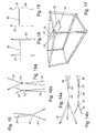
Die folgenden Figuren sind Anwendungsbeispiele für das Modul Horizontallashing:
-
Figur 3 -
Figur 4 -
Figur 5 -
Figur 6 -
Figur 7 -
Figur 8
-
FIG. 3 shows the exemplary arrangement of a Horizontallashing pair, each with two single strands (15) in a preferred embodiment of the lashing system positioned in eyelet no. 3 (14) of the two inner bottom rails in a container with not shown charge. The single strands (15) are connected to a buckle (16). -
FIG. 4 shows the construction of a horizontal bashing with two single strands (15) and container hooks (11). The length of the single strands is between 3 and 12 m. The total length of a required for two single strands webbing is between 6 and 24 m. For a preferred Execution of the lashing system is the length of a single strand 5 m. The total length of a webbing required for two single strands of this design is 10 m. This design is provided in the deflection of the strap on the container hook with a sewing seam. -
FIG. 5 shows the exemplary arrangement of a Horizontallashing pair each with two single strands (17) in a preferred embodiment of the lashing system positioned in eyelet no. 3 of the two roof rails (13) of a container (1) with not shown charge. -
FIG. 6 shows the construction of a horizontal sagging, each with three single strands (18) and container hooks (11), the length of the single strands is between 3 and 12 m. For a preferred embodiment of the lashing system, the length of a single strand is 5 m. -
FIG. 7 shows the exemplary arrangement of a Horizontallashing pair, each with a single strand (18) in a preferred embodiment of the lashing system positioned in eyelet no. 3 of the two roof rails (13) of a container with not shown charge. The single strands (18) are connected to a belt lock (16). -
FIG. 8 shows the construction of a horizontal bashing, each with a single strand (19) and container hook (11). The length of the single strand is between 3 and 12 m. For a preferred embodiment of the lashing system, the length of a single strand is 5 m.
Die folgenden Figuren sind Anwendungsbeispiele für das Modul Abstandshalter:
-
Figur 9 -
Figur 10mit Lochgrößen von 5bis 6 cm undLochabständen von 5bis 6 cm. Die Löcher des Lochbandes werden mittels eines speziellen Verfahrens durch geregeltes Ein- und Ausschalten des Schussfadens im Fertigungsprozess (Weben) hergestellt. Das Gurtband wird in der Position eines Loches zweigeteilt. -
Figur 11 -
Figur 12
-
FIG. 9 shows the exemplary arrangement of a spacer pair (20) in a preferred embodiment with hooks of lashing system positioned in eyelet no. 1 of the side members (13 and 14) of a container (1) with not shown charge. -
FIG. 10 shows the construction of a spacer, each with a single strand (20) and container hook (11). The length of the single strand (20) is between 1 and 2.50 m. For a preferred embodiment of the lashing system, the length of a single strand is 2.20 m. The spacer is usually a commercially available perforated tape with hole sizes of 5 to 6 cm and hole spacing of 5 to 6 cm. The holes of the perforated belt are produced by a special process by controlled switching on and off of the weft thread in the manufacturing process (weaving). The webbing is bisected in the position of a hole. -
FIG. 11 shows the exemplary arrangement of a spacer (20) with inserted into the perforated belt (21) horizontal lashing (17). -
FIG. 12 shows the exemplary arrangement of the modules of a Horizontallashing pair, each with two single strands (15) in a preferred embodiment of the lashing system positioned in eyelet no. 3 of the two bottom rails (14), a horizontal lapel pair, each with a single strand (18) in a preferred Design of the lashing system positioned in eyelet No. 3 of the two roof side members (13), and a spacer pair (20) in a preferred embodiment with hooks of the lashing system positioned in eyelet No. 1 of the roof rails (13) of a container with not shown charge. The single strands (15 and 18) are connected to a buckle (16).
Im Status der Vorbereitung des Verzurrsystems wird jeder Strang der Horizontallashings durch eines der Löcher der Abstandshalter geführt und somit die Höhenposition der Horizontallashings bestimmt.In the condition of preparing the lashing system, each strand of horizontal sagging is guided through one of the holes of the spacers and thus determines the height position of the horizontal saggings.
Die folgenden Figuren sind Anwendungsbeispiele für das Modul Toplashing:
-
Figur 13
-
FIG. 13 shows the exemplary arrangement of a top stranding with a single strand (24) in a preferred embodiment of the lashing system positioned in eyelet no. 4 of the two roof rails (13) of a container with a load, not shown.
Der Einzelstrang (24) ist über die Stegschnalle (23) in zwei Einzelstränge verzweigt und mit dem inneren Dachlängsträger (13) verbunden. Auf der anderen Seite teilt sich der Einzelstrang (24) über die Verzweigung (25) in zwei Einzelstränge (26), die mit den Gurtschlössern (16) mit anderen Lashings verbunden sind.
-
Figur 14a zeigt die Konstruktion eines Toplashings mit jeweils einem Hakenstrang (22) und Containerhaken auf beiden Seiten. Über eine Stegschnalle (23) wird ein Einzelstrang (24) zu einer Verzweigung (25) geführt, von der zwei Einzelstränge (26) ausgehen, die mit den Gurtschlössern (16) mit anderen Lashings verbunden sind. Für eine bevorzugte Ausführung des Verzurrsystems beträgt die Länge eines Toplashings zwischen 3 m und 7 m. -
Figur 14b zeigt die Konstruktion eines Toplashings mit jeweils einem Hakenstrang (22) und Containerhaken auf beiden Seiten. Über eine Stegschnalle (23) und eine Nähnaht wird eine Verzweigung (26) der Einzelstränge durchgeführt. Für eine bevorzugte Ausführung des Verzurrsystems beträgt die Länge eines Toplashings zwischen 3 m und 7 m. -
Figur 15
Für eine bevorzugte Ausführung des Verzurrsystems beträgt die Länge eines Toplashings zwischen 3 m und 7 m. -
Figur 16a zeigt die Konstruktion eines Toplashings mit jeweils einem Hakenstrang (22) und Containerhaken von oben. Über eine Stegschnalle (23) wird eine Verzweigung der Einzelstränge (26) durchgeführt. -
Figur 16b zeigt die Konstruktion eines Toplashings mit jeweils einem Hakenstrang (22) und Containerhaken von der Seite. Über eine Stegschnalle (23) wird ein Verzweigung der Einzelstränge (26) durchgeführt. -
Figur 17 -
Figur 18 -
Figur 19mit Lochabständen von 5cm bis 6 cm bzw.Lochgrößen von 5cm bis 6 cm. Die Länge des Lochbandes ist anwendungsspezifisch; dadurch dass sich die Einzelstränge durch verschiedene Öffnungen des Lochbandes führen lassen, lässt sich die Breite des Toplashings variieren. Für eine bevorzugte Ausführung des Verzurrsystems beträgt die Länge dieses Toplashings zwischen 3 m und 7 m und die Länge des Lochbandes zwischen 0,5 m bis 1,5 m. -
Figur 20 -
Figur 21- eines Horizontallashing-Paares mit jeweils zwei Einzelsträngen in einer bevorzugten Ausführung des Verzurrsystems positioniert in Öse Nr. 3 der beiden Dachlängsträger, sowie eines Horizontallashing-Paares mit jeweils zwei Einzelsträngen (15 und 17) in einer bevorzugten Ausführung des Verzurrsystems positioniert in Öse Nr. 3 der beiden Längsträger (13 und 14), sowie eines Toplashings mit einem verzweigten Einzelstrang (26) in einer bevorzugten Ausführung des Verzurrsystems positioniert in Öse Nr. 4 der beiden Dachlängsträger (13) eines Containers mit nicht dargestellter Ladung, sowie eines Abstandshalters (20) mit Containerhaken in einer bevorzugten Ausführung des Verzurrsystems positioniert in Öse Nr. 1 der Dachlängsträger des Containers (1).
-
Figure 14a shows the construction of a top lashing, each with a hook strand (22) and container hooks on both sides. Via a web buckle (23), a single strand (24) is led to a branch (25), from which two single strands (26) go out, which are connected to the belt buckles (16) with other lashings. For a preferred embodiment of the lashing system, the length of a top lashing is between 3 m and 7 m. -
FIG. 14b shows the construction of a top lashing, each with a hook strand (22) and container hooks on both sides. About a web buckle (23) and a sewing seam a branch (26) of the single strands is performed. For a preferred embodiment of the lashing system, the length of a top lashing is between 3 m and 7 m. -
FIG. 15 shows the construction of a top lashing with a hook strand (22) and container hooks on both sides. Via a sewn strip deflection (27), a branching of the individual strands (26) is carried out.
For a preferred embodiment of the lashing system, the length of a top lashing is between 3 m and 7 m. -
FIG. 16a shows the construction of a top lashing, each with a hook strand (22) and container hooks from above. About a web buckle (23) a branching of the individual strands (26) is performed. -
FIG. 16b shows the construction of a top lashing, each with a hook strand (22) and container hooks from the side. About a web buckle (23) a branching of the individual strands (26) is performed. -
FIG. 17 shows the exemplary arrangement of a top lashing with a double strand (28) in a preferred embodiment of the lashing system positioned in eyelet no. 3 of the two roof rails (13) of a container with not shown charge. The double strand is connected by means of the band connection (29) and is connected on the other side with a belt lock (16). -
FIG. 18 shows the construction of a top lashing with two hook strands (28) and container hooks (13) on both sides. Via a sewn-in solid belt connection (29), the individual strands (28) are guided to the end of the charge. For a preferred embodiment of the lashing system, the length of this top lashing is between 3 and 7 m. -
FIG. 19 shows the construction of a top lashing with two width-adjustable hook strands (28) and container hooks (13) on both sides. Via a sewn-in belt connection (29), the individual strands (28) are guided to the end of the charge. The sewn-in belt connection (29) consists of perforated belt with hole spacings of 5 cm to 6 cm or hole sizes of 5 cm to 6 cm. The length of the perforated belt is application specific; The fact that the individual strands can be guided through different openings of the perforated belt, the width of the top lashings can vary. For a preferred embodiment of the lashing system, the length of this top lashing is between 3 m and 7 m and the length of the perforated strip between 0.5 m to 1.5 m. -
FIG. 20 shows the exemplary arrangement of the modules of a Horizontallashing pair each with two single strands (17) in a preferred embodiment of the lashing system positioned in eyelet No. 3 of the two roof rails (13), and a top lashing (24) with a hook strand (22) and a branched single strand (26) in a preferred embodiment of the lashing system positioned in eyelet no. 4 of the two roof rails (13) of a container with not shown charge. The single strands are closed with belt clips (16). -
FIG. 21 shows the exemplary arrangement of the modules:- a Horizontallashing pair each with two single strands in a preferred embodiment of the lashing system positioned in eyelet no. 3 of the two roof rails, and a Horizontallashing pair each with two single strands (15 and 17) in a preferred embodiment of the lashing system positioned in eyelet no the two longitudinal members (13 and 14), and a top lashing with a branched single strand (26) in a preferred embodiment of the lashing system positioned in eyelet no. 4 of the two roof rails (13) of a container with not shown charge, and a spacer (20) with container hooks in a preferred embodiment of the lashing system positioned in eyelet no. 1 of the roof rails of the container (1).
Im Status der Vorbereitung des Verzurrsystems wird jeder Strang der Horizontallashings durch eines der Löcher der Abstandshalter (20) geführt und somit die Höhenposition der Horizontallashings bestimmt.In the state of preparation of the lashing system, each strand of horizontal sagging is passed through one of the holes of the spacers (20) and thus determines the height position of the horizontal touchdowns.
Das folgenden Beispiel betrifft den Modul Blocklashing:
-
Figur 24
-
FIG. 24 shows the exemplary arrangement of a block stranding with a single strand in a preferred embodiment of the lashing system positioned in the middle region at the load end of a container with not shown charge.
Dieser Modul besteht aus einem Gurtband bzw. Lochband (32) mit Gurtschnalle (16) und wird als zusätzliche Horizontalbindung bei mehrlagigen Containerladungen in Längen von 3 m bis 10 m eingesetzt.This module consists of a belt or perforated belt (32) with buckle (16) and is used as an additional horizontal binding in multi-layer container loads in lengths of 3 m to 10 m.
Das folgende Beispiel betrifft den Modul Backlashing:
-
Figur 25 -
Figur 26 -
Figur 2728 zeigen die beispielhafte Anordnung der Module eines Horizontallashing-Paares mit jeweils zwei Einzelsträngen (15) in einer bevorzugten Ausführung des Verzurrsystems positioniert in Öse Nr. 3 der beiden Bodenlängsträger (14), sowie eines Backlashing-Paares mit einem Einzelstrang (31) in einer bevorzugten Ausführung des Verzurrsystems positioniert in Öse Nr. 1 der beiden Bodenlängsträger (14) eines Containers mit nicht dargestellter Ladung.
-
FIG. 25 shows the exemplary arrangement of a backlashing pair (31), each with a single strand with container hooks (11) in a preferred embodiment of the lashing system positioned in the door region of the container with charge not shown. This module consists of a perforated belt with sewn-on container hook and is used as an example for single-ply container loads in lengths of 1 to 6 m. The single strands are closed by the belt lock (16). -
FIG. 26 shows the exemplary arrangement of a backlashing pair (32), each with a single strand without container hook and the buckle (16) in a preferred embodiment of the lashing system in any position of a container with not shown charge. This module consists of a perforated belt and is used as an example for single-ply container loads in lengths of 1 to 6 m. -
FIG. 27 and28 show the exemplary arrangement of the modules of a horizontal lapping pair, each with two single strands (15) in a preferred embodiment of the lashing system positioned in eyelet no. 3 of the two bottom longitudinal members (14), and a backlashing pair with a single strand (31) in a preferred embodiment of the lashing system positioned in eyelet no. 1 of the two bottom rails (14) of a container with not shown charge.
Ein Backlashing ist als Lochband ausgeführt.
Das folgende Beispiel betrifft das Modul Bodenlashing:
-
Figur 29 -
Figur 30 -
Figur 31
-
FIG. 29 FIG. 12 shows the exemplary arrangement of a bottom lashing (33) in a preferred embodiment of the lashing system positioned midway at the cargo end of this 20 'standard container with unillustrated cargo with spacer (34) and attachment strands (35) for attachment to the inside bottom rail (14) Eyelet no. 4. -
FIG. 30 shows by way of example the arrangement of a single strand glass (19) positioned in eyelet no. 3 of the two inner bottom rails (14). The single strand is connected to a buckle (16). -
FIG. 31 shows by way of example the arrangement of two single strand glassings (19), wherein a single strand lapping in eyelet no. 2 and another in eyelet no. 3 of the two inner bottom rails (14) is positioned. Each single strand of the horizontal skirting is provided with a buckle (16).
- 1.1.
- ContainerContainer
- 2.Second
- Containerbodencontainer floor
- 3.Third
- Türdoor
- 4.4th
- Stirnwandbulkhead
- 5.5th
- Containerdachcontainer roof
- 6.6th
- BodenlängsträgerFloor side members
- 7.7th
- DachlängsträgerRoof rails
- 8.8th.
- TürecksäuleTürecksäule
- 9.9th
- Ecksäule an der StirnwandCorner column on the front wall
- 10.10th
- Verzurröselashing
- 11.11th
- Containerhakencontainer hooks
- 12.12th
- LashingLashing
- 13.13th
- innerer Dachlängsträger (7) mit Verzurrösen (10)Inner roof runner (7) with lashing eyes (10)
- 14.14th
- innerer Bodenlängsträger (6) mit Verzurrösen (10)Inner bottom rail (6) with lashing eyes (10)
- 15.15th
- Lashing für horizontale Doppelverzurrung an 14)Lashing for horizontal double lashing 14)
- 16.16th
- Gurtschlossbuckle
- 17.17th
- Lashing für horizontale Doppelverzurrung an (13)Lashing for horizontal double lashing (13)
- 18.18th
- Lashing für horizontale Einfachverzurrung an (13)Lashing for horizontal single lashing on (13)
- 19.19th
- Einzelstrang des HorizontallashingsSingle strand of horizontal-lashing
- 20.20th
- Abstandhalterspacer
- 21.21st
- Lochbandperforated tape
- 22.22nd
- Befestigungsstrang bzw. Hakenstrang des Toplashings zur Befestigung an (13)Fastening strand or hook strand of the top lashings for attachment to (13)
- 23.23rd
- Stegschnallebar buckle
- 24.24th
- Einzelstrang des ToplashingsSingle strand of top lashings
- 25.25th
- Verzweigung des Einzelstrangs (24) in zwei Stränge (26) zur Befestigung der LadungBranching of the single strand (24) into two strands (26) for securing the cargo
- 26.26th
- zwei Stränge zur Befestigung der Ladungtwo strands for securing the cargo
- 27.27th
- Bandumlenkungstrip deflection
- 28.28th
- Doppelstrang ToplashingDouble Strand Toplashing
- 29.29th
- Bandverbindung der Doppelstränge des ToplashingsBand connection of the double strands of the Toplashings
- 30.30th
- Abstandhalter im mittleren Bereich des LadungsendeSpacer in the middle area of the cargo end
- 31.31st
- Gurtband bzw. Lochband mit ContainerhakenWebbing or perforated tape with container hook
- 32.32nd
- Gurtband bzw. Lochband ohne ContainerhakenWebbing or perforated tape without container hook
- 33.33rd
- Doppelstrang BodenlashingDouble strand floor lashing
- 34.34th
- Bandverbindung der Doppelstränge des BodenlashingsBand connection of the double strands of the bottom lashing
- 35.35th
- Befestigungsstrang des Bodenlashings zur Befestigung an (13)Mounting strand of the floor lashings for attachment to (13)
Claims (34)
die Ladung über schräg gespannte Lashings mit dem Container verbunden ist,
wobei die Lashings durch senkrechte Abstandhalter fixiert werden, und das System modular aufgebaut ist.Lashing system for securing loads in containers with the help of lashings, characterized in that
the cargo is connected to the container via obliquely stretched lashings,
wherein the lashings are fixed by vertical spacers, and the system is modular.
die Ladung über schräg gespannte Lashings mit dem Containers verbunden wird und
das System modular aufgebaut wird.Method for securing loads in closed containers with the aid of lashings, characterized in that
the cargo is connected to the container via obliquely stretched lashings and
the system is modular.
Applications Claiming Priority (1)
| Application Number | Priority Date | Filing Date | Title |
|---|---|---|---|
| DE200810024720 DE102008024720A1 (en) | 2008-05-22 | 2008-05-22 | Modular lashing system for securing load units |
Publications (2)
| Publication Number | Publication Date |
|---|---|
| EP2128044A1 true EP2128044A1 (en) | 2009-12-02 |
| EP2128044B1 EP2128044B1 (en) | 2014-09-17 |
Family
ID=41055197
Family Applications (1)
| Application Number | Title | Priority Date | Filing Date |
|---|---|---|---|
| EP20090006674 Active EP2128044B1 (en) | 2008-05-22 | 2009-05-18 | Modular lashing system for the securing of loading units, Method for securing loading units in closed containers |
Country Status (2)
| Country | Link |
|---|---|
| EP (1) | EP2128044B1 (en) |
| DE (2) | DE102008024720A1 (en) |
Cited By (5)
| Publication number | Priority date | Publication date | Assignee | Title |
|---|---|---|---|---|
| EP2397364A1 (en) * | 2010-05-15 | 2011-12-21 | Fahrzeugwerk Bernard Krone GmbH | Device for fixing load securing elements |
| ES2376333A1 (en) * | 2010-03-09 | 2012-03-13 | Vasco Gallega De Consignaciones, S.L. | Granite blocks subject systems in transportable containers on ships. (Machine-translation by Google Translate, not legally binding) |
| CN104058064A (en) * | 2013-03-21 | 2014-09-24 | 上海江南长兴重工有限责任公司 | Method for mounting container foot base cones of container ship |
| CN110525808A (en) * | 2019-09-06 | 2019-12-03 | 龙岩市腾兴机械维修有限公司 | A kind of logistics container |
| WO2023041793A1 (en) * | 2021-09-20 | 2023-03-23 | Cordstrap B.V. | System for lashing a container load and use thereof |
Families Citing this family (1)
| Publication number | Priority date | Publication date | Assignee | Title |
|---|---|---|---|---|
| DE102017001817A1 (en) | 2017-02-27 | 2018-08-30 | Rainer Gmbh | Lashing system for securing cargo in a container |
Citations (10)
| Publication number | Priority date | Publication date | Assignee | Title |
|---|---|---|---|---|
| US2197598A (en) | 1938-07-13 | 1940-04-16 | Harry C Way | Packaging or crating structure |
| DE3443662C1 (en) | 1984-11-30 | 1986-06-26 | Daimler-Benz Ag, 7000 Stuttgart | Device for lashing vehicles equipped with vehicle-jacking receptacles on a loading surface of a transport device, in particular a pallet for air freighting |
| US5398832A (en) * | 1992-10-27 | 1995-03-21 | Clive-Smith; Martin | Lashings in folding flatrack |
| DE19522138A1 (en) | 1995-06-19 | 1996-01-18 | Horst Laug | Transporting lock for machines etc. on rollers |
| US5551379A (en) * | 1995-04-17 | 1996-09-03 | Hart; Marcie J. | Multiple use motion restraint device |
| US5813536A (en) | 1996-11-07 | 1998-09-29 | Menasha Corporation | Packaging structure for a bundle of panels |
| DE20009454U1 (en) | 2000-05-29 | 2000-08-24 | Weber Ulrich | Device for mounting a transverse bulkhead in steel containers |
| EP1661758A2 (en) * | 2004-11-24 | 2006-05-31 | Industrias Ponsa, S.A. | Device for stowing loads at the interior of containers |
| DE102005039789B3 (en) * | 2005-08-22 | 2006-10-26 | Rainer Gmbh | Lashing system to strap loads onto carrier using straps consisting of upper part with positioning piece and lower part with connecting piece |
| US20070267410A1 (en) * | 2006-05-19 | 2007-11-22 | Illinois Tool Works Inc. | Reinforcing or restraining strap or gusset system for rear wall member of bulk material cargo container liner |
-
2008
- 2008-05-22 DE DE200810024720 patent/DE102008024720A1/en not_active Withdrawn
-
2009
- 2009-05-18 EP EP20090006674 patent/EP2128044B1/en active Active
- 2009-05-18 DE DE200920018959 patent/DE202009018959U1/en not_active Expired - Lifetime
Patent Citations (10)
| Publication number | Priority date | Publication date | Assignee | Title |
|---|---|---|---|---|
| US2197598A (en) | 1938-07-13 | 1940-04-16 | Harry C Way | Packaging or crating structure |
| DE3443662C1 (en) | 1984-11-30 | 1986-06-26 | Daimler-Benz Ag, 7000 Stuttgart | Device for lashing vehicles equipped with vehicle-jacking receptacles on a loading surface of a transport device, in particular a pallet for air freighting |
| US5398832A (en) * | 1992-10-27 | 1995-03-21 | Clive-Smith; Martin | Lashings in folding flatrack |
| US5551379A (en) * | 1995-04-17 | 1996-09-03 | Hart; Marcie J. | Multiple use motion restraint device |
| DE19522138A1 (en) | 1995-06-19 | 1996-01-18 | Horst Laug | Transporting lock for machines etc. on rollers |
| US5813536A (en) | 1996-11-07 | 1998-09-29 | Menasha Corporation | Packaging structure for a bundle of panels |
| DE20009454U1 (en) | 2000-05-29 | 2000-08-24 | Weber Ulrich | Device for mounting a transverse bulkhead in steel containers |
| EP1661758A2 (en) * | 2004-11-24 | 2006-05-31 | Industrias Ponsa, S.A. | Device for stowing loads at the interior of containers |
| DE102005039789B3 (en) * | 2005-08-22 | 2006-10-26 | Rainer Gmbh | Lashing system to strap loads onto carrier using straps consisting of upper part with positioning piece and lower part with connecting piece |
| US20070267410A1 (en) * | 2006-05-19 | 2007-11-22 | Illinois Tool Works Inc. | Reinforcing or restraining strap or gusset system for rear wall member of bulk material cargo container liner |
Cited By (7)
| Publication number | Priority date | Publication date | Assignee | Title |
|---|---|---|---|---|
| ES2376333A1 (en) * | 2010-03-09 | 2012-03-13 | Vasco Gallega De Consignaciones, S.L. | Granite blocks subject systems in transportable containers on ships. (Machine-translation by Google Translate, not legally binding) |
| EP2397364A1 (en) * | 2010-05-15 | 2011-12-21 | Fahrzeugwerk Bernard Krone GmbH | Device for fixing load securing elements |
| CN104058064A (en) * | 2013-03-21 | 2014-09-24 | 上海江南长兴重工有限责任公司 | Method for mounting container foot base cones of container ship |
| CN104058064B (en) * | 2013-03-21 | 2016-08-10 | 上海江南长兴重工有限责任公司 | Container ship case sole cone installation method |
| CN110525808A (en) * | 2019-09-06 | 2019-12-03 | 龙岩市腾兴机械维修有限公司 | A kind of logistics container |
| CN110525808B (en) * | 2019-09-06 | 2021-04-02 | 安溪县桃舟乡同盛茶叶专业合作社 | Container for logistics |
| WO2023041793A1 (en) * | 2021-09-20 | 2023-03-23 | Cordstrap B.V. | System for lashing a container load and use thereof |
Also Published As
| Publication number | Publication date |
|---|---|
| DE102008024720A1 (en) | 2009-12-10 |
| EP2128044B1 (en) | 2014-09-17 |
| DE202009018959U1 (en) | 2014-11-12 |
Similar Documents
| Publication | Publication Date | Title |
|---|---|---|
| EP2128044B1 (en) | Modular lashing system for the securing of loading units, Method for securing loading units in closed containers | |
| EP2844520B1 (en) | Transport vehicle | |
| DE4441610C2 (en) | Safety net arrangement | |
| DE202008016326U1 (en) | Device for securing cargo | |
| DE102008014740B3 (en) | Transport safety arrangement for containers | |
| DE102009060472A1 (en) | Flexible bulk material container has carrying straps in its upper area, over which bulk material container is lifted, and opening | |
| DE102008011704A1 (en) | Arrangement for use with commercial vehicle for securing load arranged on flat loading area of commercial vehicle frame, comprises coil cavity and pulling eyelets arranged outside coil cavity | |
| DE102014001331B3 (en) | Protective cover for a transport cart | |
| DE102005039789B3 (en) | Lashing system to strap loads onto carrier using straps consisting of upper part with positioning piece and lower part with connecting piece | |
| EP1186470B1 (en) | Trailer for transporting gas bottles with high service pressure | |
| EP3247589B1 (en) | Transport vehicle | |
| DE102009053869A1 (en) | Modular restraint system for protecting e.g. loading units in standard-overseas-container, has belt forming angle with bottom and/or roof of container, where angle is equal to or smaller than specific value | |
| EP1634767A2 (en) | Device to secure load | |
| DE2854505A1 (en) | Load tying down device - is capable of being used in any form of transport and consists of net structure held together by ring elements | |
| DE202005002419U1 (en) | Load securing device for fixing load to loading surface or walls in vehicle, has tensioning belts attached to non-elastic belt around edge of cover placed over load | |
| DE102005060100B3 (en) | Tie-down system for drums involves forming loop from strapping belts taken to head part of drums, and passing tensioning belt through load-carrier | |
| DE102021107986A1 (en) | SLIDING CURTAIN WITH STANDING REINFORCEMENT TAPES AND SLIDING TARPAULIN SEMI | |
| DE102006005507B4 (en) | Fassverzurrung | |
| EP3069929B1 (en) | Use of a hole in a transverse beam | |
| DE102020002178B3 (en) | Webbing for roof tarpaulins for elastic coupling of neighboring elements of the truck body | |
| DE202015100004U1 (en) | Device for securing cargo on a loading surface | |
| DE10330504B4 (en) | Restraint system for installation in the area of the door-side opening of a loaded container | |
| DE10043972A1 (en) | Trailer for transporting pressurized gas cylinders has horizontal support frame with longitudinal and transverse edges, vertical bar pairs or plates on ends of transverse edges, gas cylinders, and restraining devices | |
| DE10114409B4 (en) | Device and method for fastening a transport good on the loading area of a transport vehicle | |
| DE2540504A1 (en) | Securing rail for lorry loads - with belt threaded through slots in rail screwed to side of lorry |
Legal Events
| Date | Code | Title | Description |
|---|---|---|---|
| PUAI | Public reference made under article 153(3) epc to a published international application that has entered the european phase |
Free format text: ORIGINAL CODE: 0009012 |
|
| AK | Designated contracting states |
Kind code of ref document: A1 Designated state(s): AT BE BG CH CY CZ DE DK EE ES FI FR GB GR HR HU IE IS IT LI LT LU LV MC MK MT NL NO PL PT RO SE SI SK TR |
|
| 17P | Request for examination filed |
Effective date: 20091202 |
|
| 17Q | First examination report despatched |
Effective date: 20091230 |
|
| GRAP | Despatch of communication of intention to grant a patent |
Free format text: ORIGINAL CODE: EPIDOSNIGR1 |
|
| INTG | Intention to grant announced |
Effective date: 20140417 |
|
| GRAS | Grant fee paid |
Free format text: ORIGINAL CODE: EPIDOSNIGR3 |
|
| GRAA | (expected) grant |
Free format text: ORIGINAL CODE: 0009210 |
|
| AK | Designated contracting states |
Kind code of ref document: B1 Designated state(s): AT BE BG CH CY CZ DE DK EE ES FI FR GB GR HR HU IE IS IT LI LT LU LV MC MK MT NL NO PL PT RO SE SI SK TR |
|
| REG | Reference to a national code |
Ref country code: GB Ref legal event code: FG4D Free format text: NOT ENGLISH |
|
| REG | Reference to a national code |
Ref country code: CH Ref legal event code: EP |
|
| REG | Reference to a national code |
Ref country code: IE Ref legal event code: FG4D Free format text: LANGUAGE OF EP DOCUMENT: GERMAN |
|
| REG | Reference to a national code |
Ref country code: AT Ref legal event code: REF Ref document number: 687584 Country of ref document: AT Kind code of ref document: T Effective date: 20141015 |
|
| REG | Reference to a national code |
Ref country code: DE Ref legal event code: R096 Ref document number: 502009009965 Country of ref document: DE Effective date: 20141030 |
|
| REG | Reference to a national code |
Ref country code: NL Ref legal event code: T3 |
|
| PG25 | Lapsed in a contracting state [announced via postgrant information from national office to epo] |
Ref country code: FI Free format text: LAPSE BECAUSE OF FAILURE TO SUBMIT A TRANSLATION OF THE DESCRIPTION OR TO PAY THE FEE WITHIN THE PRESCRIBED TIME-LIMIT Effective date: 20140917 Ref country code: SE Free format text: LAPSE BECAUSE OF FAILURE TO SUBMIT A TRANSLATION OF THE DESCRIPTION OR TO PAY THE FEE WITHIN THE PRESCRIBED TIME-LIMIT Effective date: 20140917 Ref country code: NO Free format text: LAPSE BECAUSE OF FAILURE TO SUBMIT A TRANSLATION OF THE DESCRIPTION OR TO PAY THE FEE WITHIN THE PRESCRIBED TIME-LIMIT Effective date: 20141217 Ref country code: LT Free format text: LAPSE BECAUSE OF FAILURE TO SUBMIT A TRANSLATION OF THE DESCRIPTION OR TO PAY THE FEE WITHIN THE PRESCRIBED TIME-LIMIT Effective date: 20140917 Ref country code: GR Free format text: LAPSE BECAUSE OF FAILURE TO SUBMIT A TRANSLATION OF THE DESCRIPTION OR TO PAY THE FEE WITHIN THE PRESCRIBED TIME-LIMIT Effective date: 20141218 |
|
| REG | Reference to a national code |
Ref country code: LT Ref legal event code: MG4D |
|
| PG25 | Lapsed in a contracting state [announced via postgrant information from national office to epo] |
Ref country code: HR Free format text: LAPSE BECAUSE OF FAILURE TO SUBMIT A TRANSLATION OF THE DESCRIPTION OR TO PAY THE FEE WITHIN THE PRESCRIBED TIME-LIMIT Effective date: 20140917 Ref country code: LV Free format text: LAPSE BECAUSE OF FAILURE TO SUBMIT A TRANSLATION OF THE DESCRIPTION OR TO PAY THE FEE WITHIN THE PRESCRIBED TIME-LIMIT Effective date: 20140917 Ref country code: CY Free format text: LAPSE BECAUSE OF FAILURE TO SUBMIT A TRANSLATION OF THE DESCRIPTION OR TO PAY THE FEE WITHIN THE PRESCRIBED TIME-LIMIT Effective date: 20140917 |
|
| PG25 | Lapsed in a contracting state [announced via postgrant information from national office to epo] |
Ref country code: RO Free format text: LAPSE BECAUSE OF FAILURE TO SUBMIT A TRANSLATION OF THE DESCRIPTION OR TO PAY THE FEE WITHIN THE PRESCRIBED TIME-LIMIT Effective date: 20140917 Ref country code: IS Free format text: LAPSE BECAUSE OF FAILURE TO SUBMIT A TRANSLATION OF THE DESCRIPTION OR TO PAY THE FEE WITHIN THE PRESCRIBED TIME-LIMIT Effective date: 20150117 Ref country code: PT Free format text: LAPSE BECAUSE OF FAILURE TO SUBMIT A TRANSLATION OF THE DESCRIPTION OR TO PAY THE FEE WITHIN THE PRESCRIBED TIME-LIMIT Effective date: 20150119 Ref country code: SK Free format text: LAPSE BECAUSE OF FAILURE TO SUBMIT A TRANSLATION OF THE DESCRIPTION OR TO PAY THE FEE WITHIN THE PRESCRIBED TIME-LIMIT Effective date: 20140917 Ref country code: ES Free format text: LAPSE BECAUSE OF FAILURE TO SUBMIT A TRANSLATION OF THE DESCRIPTION OR TO PAY THE FEE WITHIN THE PRESCRIBED TIME-LIMIT Effective date: 20140917 Ref country code: CZ Free format text: LAPSE BECAUSE OF FAILURE TO SUBMIT A TRANSLATION OF THE DESCRIPTION OR TO PAY THE FEE WITHIN THE PRESCRIBED TIME-LIMIT Effective date: 20140917 Ref country code: EE Free format text: LAPSE BECAUSE OF FAILURE TO SUBMIT A TRANSLATION OF THE DESCRIPTION OR TO PAY THE FEE WITHIN THE PRESCRIBED TIME-LIMIT Effective date: 20140917 |
|
| PG25 | Lapsed in a contracting state [announced via postgrant information from national office to epo] |
Ref country code: PL Free format text: LAPSE BECAUSE OF FAILURE TO SUBMIT A TRANSLATION OF THE DESCRIPTION OR TO PAY THE FEE WITHIN THE PRESCRIBED TIME-LIMIT Effective date: 20140917 |
|
| REG | Reference to a national code |
Ref country code: DE Ref legal event code: R097 Ref document number: 502009009965 Country of ref document: DE |
|
| PLBE | No opposition filed within time limit |
Free format text: ORIGINAL CODE: 0009261 |
|
| STAA | Information on the status of an ep patent application or granted ep patent |
Free format text: STATUS: NO OPPOSITION FILED WITHIN TIME LIMIT |
|
| PG25 | Lapsed in a contracting state [announced via postgrant information from national office to epo] |
Ref country code: DK Free format text: LAPSE BECAUSE OF FAILURE TO SUBMIT A TRANSLATION OF THE DESCRIPTION OR TO PAY THE FEE WITHIN THE PRESCRIBED TIME-LIMIT Effective date: 20140917 |
|
| 26N | No opposition filed |
Effective date: 20150618 |
|
| PG25 | Lapsed in a contracting state [announced via postgrant information from national office to epo] |
Ref country code: IT Free format text: LAPSE BECAUSE OF FAILURE TO SUBMIT A TRANSLATION OF THE DESCRIPTION OR TO PAY THE FEE WITHIN THE PRESCRIBED TIME-LIMIT Effective date: 20140917 |
|
| PG25 | Lapsed in a contracting state [announced via postgrant information from national office to epo] |
Ref country code: SI Free format text: LAPSE BECAUSE OF FAILURE TO SUBMIT A TRANSLATION OF THE DESCRIPTION OR TO PAY THE FEE WITHIN THE PRESCRIBED TIME-LIMIT Effective date: 20140917 |
|
| REG | Reference to a national code |
Ref country code: CH Ref legal event code: PL |
|
| PG25 | Lapsed in a contracting state [announced via postgrant information from national office to epo] |
Ref country code: LI Free format text: LAPSE BECAUSE OF NON-PAYMENT OF DUE FEES Effective date: 20150531 Ref country code: CH Free format text: LAPSE BECAUSE OF NON-PAYMENT OF DUE FEES Effective date: 20150531 Ref country code: LU Free format text: LAPSE BECAUSE OF FAILURE TO SUBMIT A TRANSLATION OF THE DESCRIPTION OR TO PAY THE FEE WITHIN THE PRESCRIBED TIME-LIMIT Effective date: 20150518 Ref country code: MC Free format text: LAPSE BECAUSE OF FAILURE TO SUBMIT A TRANSLATION OF THE DESCRIPTION OR TO PAY THE FEE WITHIN THE PRESCRIBED TIME-LIMIT Effective date: 20140917 |
|
| REG | Reference to a national code |
Ref country code: IE Ref legal event code: MM4A |
|
| REG | Reference to a national code |
Ref country code: FR Ref legal event code: PLFP Year of fee payment: 8 |
|
| PG25 | Lapsed in a contracting state [announced via postgrant information from national office to epo] |
Ref country code: IE Free format text: LAPSE BECAUSE OF NON-PAYMENT OF DUE FEES Effective date: 20150518 |
|
| PG25 | Lapsed in a contracting state [announced via postgrant information from national office to epo] |
Ref country code: MT Free format text: LAPSE BECAUSE OF FAILURE TO SUBMIT A TRANSLATION OF THE DESCRIPTION OR TO PAY THE FEE WITHIN THE PRESCRIBED TIME-LIMIT Effective date: 20140917 |
|
| REG | Reference to a national code |
Ref country code: FR Ref legal event code: PLFP Year of fee payment: 9 |
|
| PG25 | Lapsed in a contracting state [announced via postgrant information from national office to epo] |
Ref country code: HU Free format text: LAPSE BECAUSE OF FAILURE TO SUBMIT A TRANSLATION OF THE DESCRIPTION OR TO PAY THE FEE WITHIN THE PRESCRIBED TIME-LIMIT; INVALID AB INITIO Effective date: 20090518 Ref country code: BG Free format text: LAPSE BECAUSE OF FAILURE TO SUBMIT A TRANSLATION OF THE DESCRIPTION OR TO PAY THE FEE WITHIN THE PRESCRIBED TIME-LIMIT Effective date: 20140917 |
|
| PG25 | Lapsed in a contracting state [announced via postgrant information from national office to epo] |
Ref country code: TR Free format text: LAPSE BECAUSE OF FAILURE TO SUBMIT A TRANSLATION OF THE DESCRIPTION OR TO PAY THE FEE WITHIN THE PRESCRIBED TIME-LIMIT Effective date: 20140917 |
|
| REG | Reference to a national code |
Ref country code: FR Ref legal event code: PLFP Year of fee payment: 10 |
|
| PG25 | Lapsed in a contracting state [announced via postgrant information from national office to epo] |
Ref country code: MK Free format text: LAPSE BECAUSE OF FAILURE TO SUBMIT A TRANSLATION OF THE DESCRIPTION OR TO PAY THE FEE WITHIN THE PRESCRIBED TIME-LIMIT Effective date: 20140917 |
|
| PGFP | Annual fee paid to national office [announced via postgrant information from national office to epo] |
Ref country code: NL Payment date: 20230519 Year of fee payment: 15 Ref country code: FR Payment date: 20230517 Year of fee payment: 15 Ref country code: DE Payment date: 20230519 Year of fee payment: 15 |
|
| PGFP | Annual fee paid to national office [announced via postgrant information from national office to epo] |
Ref country code: AT Payment date: 20230516 Year of fee payment: 15 |
|
| PGFP | Annual fee paid to national office [announced via postgrant information from national office to epo] |
Ref country code: BE Payment date: 20230517 Year of fee payment: 15 |
|
| PGFP | Annual fee paid to national office [announced via postgrant information from national office to epo] |
Ref country code: GB Payment date: 20230522 Year of fee payment: 15 |