EP2128014A1 - Bicycle derailleur with motion resisting apparatus - Google Patents
Bicycle derailleur with motion resisting apparatus Download PDFInfo
- Publication number
- EP2128014A1 EP2128014A1 EP09150985A EP09150985A EP2128014A1 EP 2128014 A1 EP2128014 A1 EP 2128014A1 EP 09150985 A EP09150985 A EP 09150985A EP 09150985 A EP09150985 A EP 09150985A EP 2128014 A1 EP2128014 A1 EP 2128014A1
- Authority
- EP
- European Patent Office
- Prior art keywords
- movement
- chain guide
- control device
- chain
- operating element
- Prior art date
- Legal status (The legal status is an assumption and is not a legal conclusion. Google has not performed a legal analysis and makes no representation as to the accuracy of the status listed.)
- Granted
Links
Images

Classifications
-
- B—PERFORMING OPERATIONS; TRANSPORTING
- B62—LAND VEHICLES FOR TRAVELLING OTHERWISE THAN ON RAILS
- B62M—RIDER PROPULSION OF WHEELED VEHICLES OR SLEDGES; POWERED PROPULSION OF SLEDGES OR SINGLE-TRACK CYCLES; TRANSMISSIONS SPECIALLY ADAPTED FOR SUCH VEHICLES
- B62M9/00—Transmissions characterised by use of an endless chain, belt, or the like
- B62M9/04—Transmissions characterised by use of an endless chain, belt, or the like of changeable ratio
- B62M9/06—Transmissions characterised by use of an endless chain, belt, or the like of changeable ratio using a single chain, belt, or the like
- B62M9/10—Transmissions characterised by use of an endless chain, belt, or the like of changeable ratio using a single chain, belt, or the like involving different-sized wheels, e.g. rear sprocket chain wheels selectively engaged by the chain, belt, or the like
- B62M9/12—Transmissions characterised by use of an endless chain, belt, or the like of changeable ratio using a single chain, belt, or the like involving different-sized wheels, e.g. rear sprocket chain wheels selectively engaged by the chain, belt, or the like the chain, belt, or the like being laterally shiftable, e.g. using a rear derailleur
- B62M9/131—Front derailleurs
- B62M9/134—Mechanisms for shifting laterally
- B62M9/1344—Mechanisms for shifting laterally limiting or positioning the movement
- B62M9/1348—Mechanisms for shifting laterally limiting or positioning the movement characterised by the use of biasing means, e.g. springs; Arrangements thereof
-
- B—PERFORMING OPERATIONS; TRANSPORTING
- B62—LAND VEHICLES FOR TRAVELLING OTHERWISE THAN ON RAILS
- B62M—RIDER PROPULSION OF WHEELED VEHICLES OR SLEDGES; POWERED PROPULSION OF SLEDGES OR SINGLE-TRACK CYCLES; TRANSMISSIONS SPECIALLY ADAPTED FOR SUCH VEHICLES
- B62M9/00—Transmissions characterised by use of an endless chain, belt, or the like
- B62M9/04—Transmissions characterised by use of an endless chain, belt, or the like of changeable ratio
- B62M9/06—Transmissions characterised by use of an endless chain, belt, or the like of changeable ratio using a single chain, belt, or the like
- B62M9/10—Transmissions characterised by use of an endless chain, belt, or the like of changeable ratio using a single chain, belt, or the like involving different-sized wheels, e.g. rear sprocket chain wheels selectively engaged by the chain, belt, or the like
- B62M9/12—Transmissions characterised by use of an endless chain, belt, or the like of changeable ratio using a single chain, belt, or the like involving different-sized wheels, e.g. rear sprocket chain wheels selectively engaged by the chain, belt, or the like the chain, belt, or the like being laterally shiftable, e.g. using a rear derailleur
- B62M9/121—Rear derailleurs
- B62M9/124—Mechanisms for shifting laterally
- B62M9/1248—Mechanisms for shifting laterally characterised by the use of biasing means, e.g. springs; Arrangements thereof
-
- Y—GENERAL TAGGING OF NEW TECHNOLOGICAL DEVELOPMENTS; GENERAL TAGGING OF CROSS-SECTIONAL TECHNOLOGIES SPANNING OVER SEVERAL SECTIONS OF THE IPC; TECHNICAL SUBJECTS COVERED BY FORMER USPC CROSS-REFERENCE ART COLLECTIONS [XRACs] AND DIGESTS
- Y10—TECHNICAL SUBJECTS COVERED BY FORMER USPC
- Y10T—TECHNICAL SUBJECTS COVERED BY FORMER US CLASSIFICATION
- Y10T74/00—Machine element or mechanism
- Y10T74/20—Control lever and linkage systems
- Y10T74/20012—Multiple controlled elements
- Y10T74/20018—Transmission control
- Y10T74/2003—Electrical actuator
Definitions
- the present invention is directed to bicycle derailleurs and, more particularly, to a motion resisting apparatus for a bicycle derailleur.
- a typical bicycle derailleur comprises a base member for coupling to a bicycle frame, a movable member coupled for movement relative to the base member, and a chain guide coupled to the movable member for guiding a chain among a plurality of sprockets.
- the chain guide supports an upper guide pulley and a lower tension pulley, and the chain guide is pivotably mounted to the movable member through a pivot shaft.
- a spring is mounted between the movable member and the chain guide for biasing the chain guide in a clockwise direction.
- the guide pulley When the rear derailleur is mounted to the bicycle, the guide pulley is located below a plurality of rear sprockets that are mounted to the rear wheel.
- the bicycle chain coupled to the front sprocket assembly engages the top and rear of one of the plurality of rear sprockets, engages the front of the guide pulley, engages the rear of the tension pulley, and then returns to the front sprocket assembly.
- the chain moves from the currently engaged front sprocket, to the tension pulley, to the guide pulley, and then to the selected rear sprocket.
- the chain length is set so that the chain can engage the largest front sprocket and the largest rear sprocket, the chain experiences slack whenever the chain engages a smaller front sprocket and/or a smaller rear sprocket.
- the spring bias rotates the chain guide so that the tension pulley takes up the slack on the chain and prevents the chain from falling off of the sprockets.
- some rear derailleurs include one-way friction clutches that resist clockwise movement of the chain guide, and some rear derailleurs include hydraulic shock absorbers that resist sudden movement of the chain guide.
- a bicycle derailleur apparatus comprises a base member for coupling to a bicycle frame, a movable member coupled for movement relative to the base member, a chain guide coupled to the movable member for guiding a chain among a plurality of sprockets in response to movement of the movable member, and a biasing device that provides a biasing force to the chain guide for tensioning the chain.
- a movement resisting device has a control element for the application of a signal that causes the movement resisting device to change resistance to movement of the chain guide.
- Fig. 1 is a side view of a particular embodiment of a bicycle 1.
- Bicycle 1 is a mountain bicycle comprising a diamond-shaped frame 2, a front fork 3 rotatably mounted to frame 2, a handlebar 4 mounted to the upper part of fork 3, a front wheel 5 rotatably attached to the lower part of fork 3, a rear wheel 6 rotatably attached to the rear of frame 2, and a drive unit 7.
- a front wheel brake 8 is provided for braking front wheel 5, and a rear wheel brake 9 is provided for braking rear wheel 6.
- Drive unit 7 comprises a chain 23, a front sprocket assembly 19a (comprising a plurality of front sprockets) coaxially mounted with a pedal crank unit 10 having pedals, a front derailleur 17 attached to a seat tube 2b of frame 2, a rear sprocket assembly 19b (comprising a plurality of rear sprockets) coaxially mounted with rear wheel 6, and a rear derailleur 18 mounted to the rear end of a chain stay 2c of frame 2.
- front sprocket assembly 19a comprises three sprockets mounted coaxially with crank unit 10
- rear sprocket assembly 19b comprises nine sprockets mounted coaxially with rear wheel 6.
- Front derailleur 17 moves to three operating positions to switch chain 23 among selected ones of the three front sprockets
- rear derailleur 18 moves to nine operating positions to switch chain 23 among selected ones of the nine rear sprockets.
- Front derailleur 17 and rear derailleur 18 are connected to respective front and rear shift control devices 15 and 16 through front and rear shift cables 25 and 26.
- Front and rear shift control devices 15 and 16 are mounted to the inside of and in proximity to brake levers 11 and 12 mounted on handlebar 4.
- the front and rear shift control devices 15 and 16 have a symmetrical construction, and the configuration and operation of each is substantially the same except for the number of shift stages.
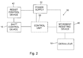
- Fig. 2 is a conceptual block diagram of a particular embodiment of a bicycle derailleur apparatus 30 that could be applied to bicycle 1.
- Bicycle derailleur apparatus 30 includes rear shift control device 16, rear derailleur 18; a resist control device 42 operatively coupled to rear shift control device 16; and a movement resisting device 46 operatively coupled to rear derailleur 18.
- front derailleur 17 and rear derailleur 18 are mechanically operated, but the teachings herein also could be applied to an electrically operated bicycle disclosed, for example, in U.S. Patent No. 6,741,045 , the entire disclosure of which is incorporated herein by reference.
- an optional control unit 50 constructed according to the teachings of U.S. Patent No. 6,741,045 , for example, is shown to illustrate the application of the teachings herein to such a bicycle.
- a power supply 52 may be operatively coupled to resist control device 42, to movement resisting device 46, and/or to control unit 50, if provided.
- Power supply 52 may be a battery, power provided from a generator, solar power, or any suitable power source.
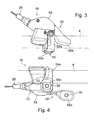
- Fig. 3 is a top view of a particular embodiment of rear shift control device 16 attached to handlebar 4
- Fig. 4 is a front view of rear shift control device 16.
- Shift control device 16 is constructed for pulling and releasing a Bowden-type shift control cable 26, and it includes a mounting bracket 54 with an annular mounting sleeve 54a that fits around handlebar 4 to fasten bracket 54 to handlebar 4 in a known manner.
- a first operating element in the form of an upshift push button 56 with a finger contact surface 56a is disposed in mounting bracket 54 below handlebar 4 as shown in Fig. 4
- a second operating element in the form of a downshift lever 58 with a finger contact surface 58a also extends below handlebar 4.
- Rear shift control device 16 may be constructed according to the teachings of U.S. patent No. 6,450,060 , the entire disclosure of which is incorporated herein by reference, modified by the teachings herein.
- An upshift resist control device in the form of an upshift resist control push button switch 62 is coupled to upshift push button 56
- a downshift resist control device in the form of a downshift resist control push button switch 66 is coupled to downshift lever 58.
- upshift resist control push button switch 62 (which may be a normally-closed contact switch) is mounted to finger contact surface 56a of upshift push button 56
- downshift resist control push button switch 66 (which may be a normally-closed contact switch) is mounted to finger contact surface 58a of downshift lever 58. Signals from upshift resist control push button switch 62 and downshift resist control push button switch 66 are communicated on a communication path 70.
- signals from upshift resist control push button switch 62 and downshift resist control push button switch 66 could be communicated wirelessly in some embodiments.
- Power from optional power supply 52 (which may be mounted anywhere on the bicycle) also could be communicated on communication path 70. However, for reasons discussed below, a power supply is not needed in this embodiment.
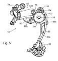
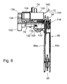
- Fig. 5 is a side view of a particular embodiment of rear derailleur 18, and Fig. 6 is a partial cross-sectional front view of rear derailleur 18.
- Rear derailleur 18 comprises a base member 74 for coupling to the rear end of chain stay 2c of frame 2, a movable member 78 coupled for movement relative to base member 74 through a linkage mechanism 82, and a chain guide 86 coupled to movable member 78 for guiding chain 23 among the plurality of sprockets in rear sprocket assembly 19b in response to movement of movable member 78.
- Linkage mechanism 82 comprises an outer link 82a and an inner link 82b, wherein outer link 82a and inner link 82b each have a first end pivotably coupled to base member 74 and a second end pivotably coupled to movable member 78.
- a return spring 90 is coupled between base member 74 and movable member 78 in a conventional manner to bias chain guide 86 laterally outwardly.
- Chain guide 86 comprises a pair of support plates 86a and 86b that rotatably support an upper guide pulley 94 and a lower tension pulley 98.
- movable member 78 includes a cylindrical first mounting boss 102 and a cylindrical second mounting boss 104.
- a chain guide mounting bolt 114 rotatably supports guide pulley 94 and fastens support plates 86a and 86b to a pivot shaft 118 that is pivotably supported by first mounting boss 102.
- pivot shaft 118 extends through first mounting boss 102, and a chain guide control gear 122 is fixed to the outer end of pivot shaft 118 so that pivot shaft 118 and chain guide control gear 122 rotate as a unit.
- First mounting boss 102 includes a blind bore 106 for supporting a biasing device in the form of a torsion spring 110.
- a biasing device in the form of a torsion spring 110.
- One end of spring 110 is mounted to first mounting boss 102, and the other end of spring 110 is mounted to support plate 86a.
- Spring 110 provides a clockwise biasing force to chain guide 86 (as viewed in Fig. 5 ) for tensioning chain 23 in a conventional manner.
- a motor clutch 130 is mounted to second mounting boss 104.
- Motor clutch 130 includes an output shaft 134, and a clutch control gear 138 is mounted to output shaft 134 so that output shaft 134 and clutch control gear 138 rotate as a unit.
- Clutch control gear 138 engages chain guide control gear 122.
- Motor clutch 130 is coupled to communication path 70 for receiving signals from upshift resist control push button switch 62 and downshift resist control push button switch 66.
- motor clutch 130, clutch control gear 138 and chain guide control gear 122 constitute movement resisting device 46 shown in Fig. 2 that resists movement of chain guide 86 to help maintain chain tension.
- Motor clutch 130 is a normally-engaged (resistive or locked) clutch that resists or prevents rotation of clutch control gear 122 (and hence chain guide control gear 122 and chain guide 86), unless appropriate signals are provided from upshift resist control push button switch 62 or downshift resist control push button switch 66. In other words, the angular position of chain guide 86 is normally maintained. However, when the rider pushes either upshift push button 56 or downshift lever 58, the rider will simultaneously push the corresponding upshift resist control push button switch 62 or downshift resist control push button switch 66.
- upshift resist control push button switch 62 or downshift resist control push button switch 66 sets motor clutch 130 to the disengaged state so that clutch control gear 138, chain guide control gear 122, pivot shaft 118 and chain guide 86 rotate freely. This allows chain guide 86 to rotate quickly to set the proper tension of chain 23 for the destination gear without undesired resistance and decreased speed caused by prior art clutch and shock absorbing mechanisms.
- the rider removes his or her thumb from upshift push button 56 or downshift lever 58
- the corresponding upshift resist control push button switch 62 or downshift resist control push button switch 66 provides a signal that resets motor clutch 130 to the engaged state.
- chain guide 86 rotates freely while the gear shift operation takes place, but thereafter chain guide 86 is inhibited from rotating in both the clockwise and counterclockwise directions, and proper tension on chain 23 is maintained under even the harshest riding conditions.
- motor clutch 130 is an electrically-operated DC motor with two control elements in the form of input (control) terminals 140 and 144.
- the motor clutch 130 operates such that, when input terminals 140 and 144 are open, motor shaft 134 rotates relatively freely. However, when input terminals 140 and 144 are shorted, a pronounced resistance on motor shaft 130 is produced from the magnetic fields in the DC motor.
- motor clutch 130 resisted both clockwise and counterclockwise rotation of chain guide 86
- a one-way clutch could be used.
- motor clutch 130 could be replaced by an electrically operated magneto rheological shock absorber, an electromagnetic clutch, or some other electromagnetically operated resistance device.
- communication path 70 could comprise optical fibers.
- electrically-operated as used herein can be applied to devices that operate primarily by electric signals (including, of course, a resistance signal), primarily by magnetic signals, by light signals converted into electrical impulses, and equivalent signals.
- the movement resisting device could resist or prevent other chain relaxing movement whether or not such movement includes movement of chain guide 86 to guide chain 23 among the plurality of sprockets.
- upshift resist control push button switch 62 or downshift resist control push button switch 66 were respectively mounted directly to upshift push button 56 or downshift lever 58, the resist control device could be mounted elsewhere.
- the resist control device could be mounted internally to be a part of shift control switches such as those disclosed in U.S. Patent Nos. 6,216,078 or 6,698,567 .
- the resist control device could be activated by control cable 23, components within housing 54, or components at derailleur 18. While separate resist control switches were disclosed, such switches could be integrated into a single switch.
- the motor body itself or some other structural component of the motor can be deemed an input. Such is often the case when the motor housing has the ability to function as a circuit ground when the motor is attached to the bicycle frame.
- the electrical signal inputs could be replaced by mechanical signal inputs.
- the value of the input signal certainly is not limited to an open or closed resistance signal. The signal may have whatever value results in the appropriate change of resistance to the movement of chain guide 86.
- the size, shape, location or orientation of the various components may be changed as desired.
- Components that are shown directly connected or contacting each other may have intermediate structures disposed between them. Separate components may be combined, and vice versa.
- the functions of one element may be performed by two, and vice versa.
- the function of one element may be performed by another, and functions may be interchanged among the elements.
- the structures and functions of one embodiment may be adopted in another embodiment. It is not necessary for all advantages to be present in a particular embodiment at the same time. Every feature which is unique from the prior art, alone or in combination with other features, also should be considered a separate description of further inventions by the applicant, including the structural and/or functional concepts embodied by such feature(s).
Abstract
Description
- The present invention is directed to bicycle derailleurs and, more particularly, to a motion resisting apparatus for a bicycle derailleur.
- A typical bicycle derailleur comprises a base member for coupling to a bicycle frame, a movable member coupled for movement relative to the base member, and a chain guide coupled to the movable member for guiding a chain among a plurality of sprockets. In a rear derailleur, the chain guide supports an upper guide pulley and a lower tension pulley, and the chain guide is pivotably mounted to the movable member through a pivot shaft. A spring is mounted between the movable member and the chain guide for biasing the chain guide in a clockwise direction.
- When the rear derailleur is mounted to the bicycle, the guide pulley is located below a plurality of rear sprockets that are mounted to the rear wheel. The bicycle chain coupled to the front sprocket assembly engages the top and rear of one of the plurality of rear sprockets, engages the front of the guide pulley, engages the rear of the tension pulley, and then returns to the front sprocket assembly. During riding, the chain moves from the currently engaged front sprocket, to the tension pulley, to the guide pulley, and then to the selected rear sprocket. Because the chain length is set so that the chain can engage the largest front sprocket and the largest rear sprocket, the chain experiences slack whenever the chain engages a smaller front sprocket and/or a smaller rear sprocket. When that occurs, the spring bias rotates the chain guide so that the tension pulley takes up the slack on the chain and prevents the chain from falling off of the sprockets.
- Mountain bicycles, for example, typically are ridden over rough terrain at high speed. As a result, the bicycle often experiences severe vibrations. Such vibrations can cause the chain guide to rotate counterclockwise, thereby restoring the slack in the chain and causing the chain to malfunction. To prevent such malfunctions, some rear derailleurs include one-way friction clutches that resist clockwise movement of the chain guide, and some rear derailleurs include hydraulic shock absorbers that resist sudden movement of the chain guide.
- The present invention is directed to various features of a bicycle shift control device. In one embodiment, a bicycle derailleur apparatus comprises a base member for coupling to a bicycle frame, a movable member coupled for movement relative to the base member, a chain guide coupled to the movable member for guiding a chain among a plurality of sprockets in response to movement of the movable member, and a biasing device that provides a biasing force to the chain guide for tensioning the chain. A movement resisting device has a control element for the application of a signal that causes the movement resisting device to change resistance to movement of the chain guide. Additional inventive features will become apparent from the description below, and such features alone or in combination with the above features and their equivalents may form the basis of further inventions as recited in the claims.
-
-
Fig. 1 is a side view of a particular embodiment of a bicycle; -
Fig. 2 is a conceptual block diagram of a particular embodiment of a bicycle derailleur apparatus that includes an electrically operated movement resisting device; -
Fig. 3 is a top view of a particular embodiment of a shift control device attached to a handlebar; -
Fig. 4 is a front view of the shift control device; -
Fig. 5 is a side view of a particular embodiment of a rear derailleur that includes a movement resisting device; and -
Fig. 6 is a partial cross-sectional front view of the rear derailleur. -
Fig. 1 is a side view of a particular embodiment of a bicycle 1. Bicycle 1 is a mountain bicycle comprising a diamond-shaped frame 2, a front fork 3 rotatably mounted to frame 2, ahandlebar 4 mounted to the upper part of fork 3, afront wheel 5 rotatably attached to the lower part of fork 3, arear wheel 6 rotatably attached to the rear of frame 2, and adrive unit 7. Afront wheel brake 8 is provided for brakingfront wheel 5, and arear wheel brake 9 is provided for brakingrear wheel 6. -
Drive unit 7 comprises achain 23, afront sprocket assembly 19a (comprising a plurality of front sprockets) coaxially mounted with apedal crank unit 10 having pedals, a front derailleur 17 attached to aseat tube 2b of frame 2, arear sprocket assembly 19b (comprising a plurality of rear sprockets) coaxially mounted withrear wheel 6, and arear derailleur 18 mounted to the rear end of a chain stay 2c of frame 2. In this embodiment,front sprocket assembly 19a comprises three sprockets mounted coaxially withcrank unit 10, andrear sprocket assembly 19b comprises nine sprockets mounted coaxially withrear wheel 6. Front derailleur 17 moves to three operating positions to switchchain 23 among selected ones of the three front sprockets, andrear derailleur 18 moves to nine operating positions to switchchain 23 among selected ones of the nine rear sprockets. - Front derailleur 17 and
rear derailleur 18 are connected to respective front and rearshift control devices rear shift cables shift control devices brake levers handlebar 4. The front and rearshift control devices -
Fig. 2 is a conceptual block diagram of a particular embodiment of abicycle derailleur apparatus 30 that could be applied to bicycle 1.Bicycle derailleur apparatus 30 includes rearshift control device 16,rear derailleur 18; aresist control device 42 operatively coupled to rearshift control device 16; and amovement resisting device 46 operatively coupled torear derailleur 18. In this embodiment, front derailleur 17 andrear derailleur 18 are mechanically operated, but the teachings herein also could be applied to an electrically operated bicycle disclosed, for example, inU.S. Patent No. 6,741,045 , the entire disclosure of which is incorporated herein by reference. - Accordingly, an
optional control unit 50 constructed according to the teachings ofU.S. Patent No. 6,741,045 , for example, is shown to illustrate the application of the teachings herein to such a bicycle. Depending upon the application, apower supply 52 may be operatively coupled to resistcontrol device 42, tomovement resisting device 46, and/or to controlunit 50, if provided.Power supply 52 may be a battery, power provided from a generator, solar power, or any suitable power source. -
Fig. 3 is a top view of a particular embodiment of rearshift control device 16 attached tohandlebar 4, andFig. 4 is a front view of rearshift control device 16.Shift control device 16 is constructed for pulling and releasing a Bowden-typeshift control cable 26, and it includes amounting bracket 54 with anannular mounting sleeve 54a that fits aroundhandlebar 4 to fastenbracket 54 to handlebar 4 in a known manner. A first operating element in the form of anupshift push button 56 with afinger contact surface 56a is disposed inmounting bracket 54 belowhandlebar 4 as shown inFig. 4 , and a second operating element in the form of adownshift lever 58 with afinger contact surface 58a also extends belowhandlebar 4. As a result, the operation of both operating elements is possible with the thumb of thehand gripping handlebar 4. Rearshift control device 16 may be constructed according to the teachings ofU.S. patent No. 6,450,060 , the entire disclosure of which is incorporated herein by reference, modified by the teachings herein. - An upshift resist control device in the form of an upshift resist control
push button switch 62 is coupled toupshift push button 56, and a downshift resist control device in the form of a downshift resist controlpush button switch 66 is coupled todownshift lever 58. More specifically, in this embodiment, upshift resist control push button switch 62 (which may be a normally-closed contact switch) is mounted tofinger contact surface 56a ofupshift push button 56, and downshift resist control push button switch 66 (which may be a normally-closed contact switch) is mounted tofinger contact surface 58a ofdownshift lever 58. Signals from upshift resist controlpush button switch 62 and downshift resist controlpush button switch 66 are communicated on acommunication path 70. Of course, signals from upshift resist controlpush button switch 62 and downshift resist controlpush button switch 66 could be communicated wirelessly in some embodiments. Power from optional power supply 52 (which may be mounted anywhere on the bicycle) also could be communicated oncommunication path 70. However, for reasons discussed below, a power supply is not needed in this embodiment. -
Fig. 5 is a side view of a particular embodiment ofrear derailleur 18, andFig. 6 is a partial cross-sectional front view ofrear derailleur 18. Rearderailleur 18 comprises abase member 74 for coupling to the rear end of chain stay 2c of frame 2, amovable member 78 coupled for movement relative tobase member 74 through alinkage mechanism 82, and achain guide 86 coupled tomovable member 78 for guidingchain 23 among the plurality of sprockets inrear sprocket assembly 19b in response to movement ofmovable member 78.Linkage mechanism 82 comprises anouter link 82a and aninner link 82b, whereinouter link 82a andinner link 82b each have a first end pivotably coupled tobase member 74 and a second end pivotably coupled tomovable member 78. Areturn spring 90 is coupled betweenbase member 74 andmovable member 78 in a conventional manner to biaschain guide 86 laterally outwardly.Chain guide 86 comprises a pair ofsupport plates upper guide pulley 94 and alower tension pulley 98. - As shown in
Fig. 6 ,movable member 78 includes a cylindricalfirst mounting boss 102 and a cylindricalsecond mounting boss 104. A chainguide mounting bolt 114 rotatably supportsguide pulley 94 and fastenssupport plates pivot shaft 118 that is pivotably supported byfirst mounting boss 102. In this embodiment,pivot shaft 118 extends throughfirst mounting boss 102, and a chainguide control gear 122 is fixed to the outer end ofpivot shaft 118 so thatpivot shaft 118 and chainguide control gear 122 rotate as a unit. -
First mounting boss 102 includes ablind bore 106 for supporting a biasing device in the form of atorsion spring 110. One end ofspring 110 is mounted tofirst mounting boss 102, and the other end ofspring 110 is mounted to supportplate 86a.Spring 110 provides a clockwise biasing force to chain guide 86 (as viewed inFig. 5 ) fortensioning chain 23 in a conventional manner. - A
motor clutch 130 is mounted tosecond mounting boss 104.Motor clutch 130 includes anoutput shaft 134, and aclutch control gear 138 is mounted tooutput shaft 134 so thatoutput shaft 134 andclutch control gear 138 rotate as a unit.Clutch control gear 138 engages chainguide control gear 122.Motor clutch 130 is coupled tocommunication path 70 for receiving signals from upshift resist controlpush button switch 62 and downshift resist controlpush button switch 66. In this embodiment,motor clutch 130,clutch control gear 138 and chainguide control gear 122 constitutemovement resisting device 46 shown inFig. 2 that resists movement ofchain guide 86 to help maintain chain tension. -
Motor clutch 130 is a normally-engaged (resistive or locked) clutch that resists or prevents rotation of clutch control gear 122 (and hence chainguide control gear 122 and chain guide 86), unless appropriate signals are provided from upshift resist controlpush button switch 62 or downshift resist controlpush button switch 66. In other words, the angular position ofchain guide 86 is normally maintained. However, when the rider pushes eitherupshift push button 56 or downshiftlever 58, the rider will simultaneously push the corresponding upshift resist controlpush button switch 62 or downshift resist controlpush button switch 66. The signal provided by upshift resist controlpush button switch 62 or downshift resist controlpush button switch 66 sets motor clutch 130 to the disengaged state so thatclutch control gear 138, chainguide control gear 122,pivot shaft 118 and chain guide 86 rotate freely. This allowschain guide 86 to rotate quickly to set the proper tension ofchain 23 for the destination gear without undesired resistance and decreased speed caused by prior art clutch and shock absorbing mechanisms. When the rider removes his or her thumb fromupshift push button 56 or downshiftlever 58, the corresponding upshift resist controlpush button switch 62 or downshift resist controlpush button switch 66 provides a signal that resetsmotor clutch 130 to the engaged state. As a result,chain guide 86 rotates freely while the gear shift operation takes place, but thereafter chain guide 86 is inhibited from rotating in both the clockwise and counterclockwise directions, and proper tension onchain 23 is maintained under even the harshest riding conditions. - In this embodiment,
motor clutch 130 is an electrically-operated DC motor with two control elements in the form of input (control)terminals motor clutch 130 operates such that, wheninput terminals motor shaft 134 rotates relatively freely. However, wheninput terminals motor shaft 130 is produced from the magnetic fields in the DC motor. Thus, when combined with a normally-closed upshift resist controlpush button switch 62 and a normally-closed downshift resist controlpush button switch 66, connected in series betweeninput terminals input terminals motor clutch 130 are normally shorted to a first operating condition (i.e.,input terminals motor clutch 130 is in a normally-engaged resistive state that resists rotation of clutch control gear 122 (and hence chainguide control gear 122 and chain guide 86). When either upshift resist controlpush button switch 62 or downshift resist controlpush button switch 66 is pressed, then continuity is broken (i.e.,input terminals input terminals motor clutch 130 are in an open second operating condition, andclutch control gear 138, chainguide control gear 122,pivot shaft 118 and chain guide 86 rotate freely. - While the above is a description of various embodiments of inventive features, further modifications may be employed without departing from the spirit and scope of the present invention. For example, while
motor clutch 130 resisted both clockwise and counterclockwise rotation ofchain guide 86, a one-way clutch could be used. Also,motor clutch 130 could be replaced by an electrically operated magneto rheological shock absorber, an electromagnetic clutch, or some other electromagnetically operated resistance device. In some applications,communication path 70 could comprise optical fibers. Thus, the term "electrically-operated" as used herein can be applied to devices that operate primarily by electric signals (including, of course, a resistance signal), primarily by magnetic signals, by light signals converted into electrical impulses, and equivalent signals. While rotation ofchain guide 86 was resisted, the movement resisting device could resist or prevent other chain relaxing movement whether or not such movement includes movement ofchain guide 86 to guidechain 23 among the plurality of sprockets. While upshift resist controlpush button switch 62 or downshift resist controlpush button switch 66 were respectively mounted directly to upshiftpush button 56 or downshiftlever 58, the resist control device could be mounted elsewhere. For example, the resist control device could be mounted internally to be a part of shift control switches such as those disclosed inU.S. Patent Nos. 6,216,078 or6,698,567 . The resist control device could be activated bycontrol cable 23, components withinhousing 54, or components atderailleur 18. While separate resist control switches were disclosed, such switches could be integrated into a single switch. Also, the motor body itself or some other structural component of the motor can be deemed an input. Such is often the case when the motor housing has the ability to function as a circuit ground when the motor is attached to the bicycle frame. The electrical signal inputs could be replaced by mechanical signal inputs. Also, the value of the input signal certainly is not limited to an open or closed resistance signal. The signal may have whatever value results in the appropriate change of resistance to the movement ofchain guide 86. - The size, shape, location or orientation of the various components may be changed as desired. Components that are shown directly connected or contacting each other may have intermediate structures disposed between them. Separate components may be combined, and vice versa. The functions of one element may be performed by two, and vice versa. The function of one element may be performed by another, and functions may be interchanged among the elements. The structures and functions of one embodiment may be adopted in another embodiment. It is not necessary for all advantages to be present in a particular embodiment at the same time. Every feature which is unique from the prior art, alone or in combination with other features, also should be considered a separate description of further inventions by the applicant, including the structural and/or functional concepts embodied by such feature(s). Terms of degree such as "substantially," "about" and "approximately" as used herein include a reasonable amount of deviation of the modified term such that the end result is not significantly changed. For example, such terms may include a deviation of at least ± 5% of the modified term as long as such a deviation would not negate the meaning of the word it modifies. Thus, the scope of the invention should not be limited by the specific structures disclosed or the apparent initial focus or emphasis on a particular structure or feature.
Claims (22)
- A bicycle derailleur apparatus comprising:a base member (74) for coupling to a bicycle frame;a movable member (78) coupled for movement relative to the base member;a chain guide (26) coupled to the movable member for guiding a chain among a plurality of sprockets in response to movement of the movable member;a biasing device (110) that provides a biasing force to the chain guide for tensioning the chain; characterized in that it comprisesa movement resisting device (46) with a control element for the application of a signal that causes the movement resisting device to change resistance to movement of the chain guide.
- The apparatus according to claim 1, characterized in that the movement resisting device (46) is an electrically-operated movement resisting device.
- The apparatus according to claim 1, characterized in that the movement resisting device includes a movement preventing device that prevents movement of the chain guide (86) other than movement of the chain guide to guide the chain among the plurality of sprockets (19b).
- The apparatus according to claim 1, characterized in that it further comprises a resist control device (42) that controls the operation of the movement resisting device.
- The apparatus according to claim 4, characterized in that the resist control device comprises a switch (66).
- The apparatus according to claim 4, characterized in that it further comprises a shift control device (16) that is used to control movement of the chain guide among the plurality of sprockets, wherein the resist control device (42) is mounted in close proximity to the shift control device.
- The apparatus according to claim 6, characterized in that the resist control device (42) is coupled to the shift control device (16).
- The apparatus according to claim 7, characterized in that the shift control device (16) includes an operating element, and wherein the resist control device (42) is coupled to the operating element (56, 58).
- The apparatus according to claim 8, characterized in that the resist control device (42) moves during operation of the operating element.
- The apparatus according to claim 9, characterized in that the resist control device (42) operates the movement resisting device during operation of the operating element (56, 58).
- The apparatus according to claim 10, characterized in that the resist control device (42) moves together with the operating element (56, 58) during operation of the operating element.
- The apparatus according to claim 11, characterized in that the resist control device (42) comprises a switch (66) that is operated during the operation of the operating element.
- The apparatus according to claim 12, characterized in that the switch (66) is mounted to a manually operated portion of the operating element.
- The apparatus according to claim 13, characterized in that the switch (66) is mounted to a surface (58a) of the operating element that is manually pressed to operate the operating element.
- The apparatus according to claim 14, characterized in that the switch (66) comprises a push button.
- The apparatus according to claim 14, characterized in that the operating element comprises a lever (58).
- The apparatus according to claim 14, characterized in that the operating element comprises a push button (56).
- The apparatus according to claim 1, characterized in that the chain guide (86) is rotatably coupled to the movable member, wherein the biasing device (110) biases the chain guide to rotate in a first rotational direction, and wherein the movement resisting device (46) resists rotation of the chain guide in a second rotational direction opposite the first rotational direction.
- The apparatus according to claim 18, characterized in that the movement resisting device (46) resists rotation of the chain guide in the first rotational direction and in the second rotational direction.
- The apparatus according to claim 19, characterized in that it further comprises:a resist control device (42) that controls the operation of the movement resisting device; anda shift control device (16) including a manually operated operating element that is used to control the movement of the chain guide (86) among the plurality of sprockets,wherein the resist control device (42) comprises a switch mounted to a surface of the operating element that is pressed to operate the operating element.
- The apparatus according to claim 20, characterized in that the switch comprises a push button (66).
- A bicycle derailleur apparatus comprising:a base member (74) for coupling to a bicycle frame;a movable member (78) coupled for movement relative to the base member;a chain guide (86) coupled to the movable member for guiding a chain among a plurality of sprockets in response to movement of the movable member;a biasing device (110) that provides a biasing force to the chain guide for tensioning the chain; characterized in thata movement resisting device (42) operatively coupled to the chain guide so that the movement resisting device changes resistance to movement of the chain guide in a first rotational direction and in a second rotational direction when the movement resisting device changes between a first operating condition and a second operating condition.
Applications Claiming Priority (1)
| Application Number | Priority Date | Filing Date | Title |
|---|---|---|---|
| US12/126,958 US8202182B2 (en) | 2008-05-26 | 2008-05-26 | Motion resisting apparatus for a bicycle derailleur |
Publications (2)
| Publication Number | Publication Date |
|---|---|
| EP2128014A1 true EP2128014A1 (en) | 2009-12-02 |
| EP2128014B1 EP2128014B1 (en) | 2016-05-18 |
Family
ID=41055328
Family Applications (1)
| Application Number | Title | Priority Date | Filing Date |
|---|---|---|---|
| EP09150985.1A Active EP2128014B1 (en) | 2008-05-26 | 2009-01-21 | Bicycle derailleur with motion resisting apparatus |
Country Status (4)
| Country | Link |
|---|---|
| US (2) | US8202182B2 (en) |
| EP (1) | EP2128014B1 (en) |
| CN (2) | CN101590897B (en) |
| TW (2) | TWI392622B (en) |
Cited By (11)
| Publication number | Priority date | Publication date | Assignee | Title |
|---|---|---|---|---|
| EP2189367A1 (en) * | 2008-11-20 | 2010-05-26 | Shimano, Inc. | Bicycle rear derailleur |
| DE202014101790U1 (en) | 2013-04-15 | 2014-05-02 | Shimano Inc. | Bicycle component control device |
| US8744699B2 (en) | 2011-10-05 | 2014-06-03 | Shimano, Inc. | Apparatus for controlling multiple bicycle operating characteristics |
| US8852041B2 (en) | 2010-09-30 | 2014-10-07 | Shimano, Inc. | Bicycle derailleur with rotation resistance |
| US8870693B2 (en) | 2012-05-21 | 2014-10-28 | Shimano, Inc. | Bicycle derailleur with rotation resistance and tactile feedback |
| US8870692B2 (en) | 2010-09-30 | 2014-10-28 | Shimano, Inc. | Bicycle derailleur with rotation resistance |
| US8882618B2 (en) | 2013-01-29 | 2014-11-11 | Shimano Inc. | Rear derailleur |
| US8900078B2 (en) | 2011-10-05 | 2014-12-02 | Shimano Inc. | Bicycle derailleur |
| US9120530B2 (en) | 2012-05-09 | 2015-09-01 | Shimano, Inc. | Bicycle derailleur with chain guide locking |
| US9290235B2 (en) | 2013-06-18 | 2016-03-22 | Shimano Inc. | Bicycle derailleur |
| US9475547B2 (en) | 2012-02-06 | 2016-10-25 | Brian Jordan | Derailleur with damping assembly |
Families Citing this family (49)
| Publication number | Priority date | Publication date | Assignee | Title |
|---|---|---|---|---|
| DE102007040156B4 (en) * | 2007-08-24 | 2013-08-29 | Shimano Inc. | Rear bicycle derailleur |
| US8979683B2 (en) * | 2012-01-31 | 2015-03-17 | Shimano Inc. | Bicycle electric actuator unit |
| DE102012204452B4 (en) * | 2012-03-20 | 2022-12-29 | Sram Deutschland Gmbh | Rear chain guide and drive arrangement for a bicycle with a large difference in the number of teeth between the largest and smallest rear sprockets |
| US9187149B2 (en) * | 2012-04-26 | 2015-11-17 | Shimano, Inc. | Bicycle derailleur with rotation resistance and resistance control |
| US8974331B2 (en) * | 2012-12-10 | 2015-03-10 | Shimano Inc. | Bicycle derailleur |
| JP2014091384A (en) * | 2012-11-01 | 2014-05-19 | Shimano Inc | Motor unit for driving bicycle transmission |
| US9400037B2 (en) * | 2013-06-04 | 2016-07-26 | Shimano Inc. | Bicycle chain tensioner |
| US9227696B2 (en) * | 2013-07-26 | 2016-01-05 | Shimano Inc. | Bicycle derailleur |
| US9377089B2 (en) * | 2013-09-12 | 2016-06-28 | Shimano Inc. | Chain tensioning device |
| US9676444B2 (en) * | 2013-10-23 | 2017-06-13 | Sram, Llc | Electromechanical rear derailleur |
| DE102014225036A1 (en) * | 2013-12-23 | 2015-06-25 | Sram Deutschland Gmbh | Bicycle decanter with friction damping |
| US9085340B1 (en) * | 2014-03-14 | 2015-07-21 | Tien Hsin Industries Co., Ltd. | Electronic front derailleur |
| ITMI20142070A1 (en) | 2014-12-02 | 2016-06-02 | Campagnolo Srl | DERAILLEUR OF A BICYCLE CHANGE AND METHOD OF ELECTRONICALLY CONTROL OF A BICYCLE CHANGE |
| ITMI20142069A1 (en) * | 2014-12-02 | 2016-06-02 | Campagnolo Srl | DERAILLEUR OF A BICYCLE CHANGE AND METHOD OF ELECTRONICALLY CONTROL OF A BICYCLE CHANGE |
| US9669900B2 (en) * | 2015-04-14 | 2017-06-06 | Shimano Inc. | Chain tensioning device |
| US10005519B2 (en) * | 2015-06-25 | 2018-06-26 | Tektro Technology Corporation | Bicycle derailleur |
| US20170066501A1 (en) * | 2015-09-08 | 2017-03-09 | Praxis Works LLC | Belt-aligned derailleur |
| TWI600583B (en) * | 2015-12-18 | 2017-10-01 | Lee Chi Entpr Co Ltd | Bicycle rear derailleur |
| US9944350B2 (en) | 2016-01-11 | 2018-04-17 | Sram, Llc | Chain guide sensor and methods of controling a bicycle |
| US9714067B1 (en) * | 2016-02-29 | 2017-07-25 | Shimano Inc. | Bicycle chain device |
| US9505461B1 (en) | 2016-04-05 | 2016-11-29 | Rene M. Ortega | Bicycle with adjustable pedaling resistance using magnetorheological based fluid |
| ITUA20163996A1 (en) | 2016-05-31 | 2017-12-01 | Campagnolo Srl | Electric bicycle derailleur |
| TWI600585B (en) * | 2016-06-24 | 2017-10-01 | 銘穗精密工業有限公司 | Pulley Assembly For Bicycle |
| TWI648198B (en) * | 2016-08-10 | 2019-01-21 | 天心工業股份有限公司 | Bicycle and its shifting device |
| CN106741556B (en) * | 2017-03-24 | 2023-04-18 | 速瑞达自行车零件(佛山)有限公司 | Rear derailleur with additional rotation resistance function and resistance applying method |
| US10435111B2 (en) | 2017-03-27 | 2019-10-08 | Sram, Llc | Fluid damper for a bicycle component |
| US11199240B2 (en) * | 2017-03-27 | 2021-12-14 | Sram, Llc | Fluid damper for a bicycle component |
| IT201700035716A1 (en) * | 2017-03-31 | 2018-10-01 | Campagnolo Srl | Bicycle rear derailleur |
| TWI641531B (en) * | 2017-05-31 | 2018-11-21 | 彥豪金屬工業股份有限公司 | Bicycle rear derailleur |
| US10577053B2 (en) * | 2017-06-06 | 2020-03-03 | Sram, Llc | Damper for a bicycle component |
| US10773773B2 (en) * | 2017-06-07 | 2020-09-15 | Shimano Inc. | Electric bicycle derailleur |
| US10882587B2 (en) * | 2017-06-26 | 2021-01-05 | Sram, Llc | Damper for a bicycle component |
| US11319021B2 (en) * | 2017-08-23 | 2022-05-03 | Shimano Inc. | Bicycle rear derailleur |
| US11897582B2 (en) * | 2017-08-25 | 2024-02-13 | The Cycle Group | Rear derailleur dampening assembly |
| EP3717341A4 (en) * | 2017-08-25 | 2021-10-27 | The Cycle Group | Rear derailleur dampening assembly |
| US11110993B2 (en) | 2017-09-13 | 2021-09-07 | Brandon Rodgers | Damping device adapted for integration within a gearshifting system |
| US11560199B2 (en) * | 2018-12-12 | 2023-01-24 | Brandon Rodgers | Gearshifting system comprising a linear actuator |
| CN108032955A (en) * | 2017-12-29 | 2018-05-15 | 珠海蓝图控制器科技有限公司 | Bicycle chain puller mounting structure and bicycle |
| TWM562815U (en) * | 2018-04-03 | 2018-07-01 | 彥豪金屬工業股份有限公司 | Derailleur assembly |
| US10807671B2 (en) * | 2018-04-16 | 2020-10-20 | Shimano Inc. | Electrical bicycle operating system |
| US11167819B2 (en) * | 2018-10-24 | 2021-11-09 | Shimano (Singapore) Pte. Ltd. | Bicycle derailleur |
| DE102019204885A1 (en) * | 2019-04-05 | 2020-10-08 | Shimano Inc. | Bicycle rear derailleur |
| US11377170B2 (en) * | 2019-10-09 | 2022-07-05 | GM Global Technology Operations LLC | Active derailleur system and method |
| CN111058205A (en) * | 2019-12-31 | 2020-04-24 | 浙江元鸿纺织科技有限公司 | Low-energy-consumption sewing machine |
| US20220081067A1 (en) * | 2020-09-11 | 2022-03-17 | Shimano Inc. | Bicycle derailleur |
| CN112849330B (en) * | 2021-01-22 | 2023-07-21 | 广东顺德顺泰智能运动器材有限公司 | Bicycle rear derailleur |
| JP2022117347A (en) | 2021-01-29 | 2022-08-10 | 株式会社シマノ | Control device for man-powered drive vehicle |
| USD1009722S1 (en) | 2021-11-10 | 2024-01-02 | The Cycle Group | One-piece chain cage for a rear derailleur |
| US11884364B2 (en) | 2021-11-10 | 2024-01-30 | The Cycle Group | Rear derailleur with one-piece chain cage |
Citations (10)
| Publication number | Priority date | Publication date | Assignee | Title |
|---|---|---|---|---|
| US4406643A (en) * | 1979-12-19 | 1983-09-27 | Shimano Industrial Company Limited | Derailleur for a bicycle |
| US4552546A (en) * | 1982-06-25 | 1985-11-12 | Ryobi Ltd. | Device for controlling the tension of a transmission chain in an externally mounted speed changer for a bicycle |
| US4692131A (en) * | 1985-05-20 | 1987-09-08 | Shimano Industrial Company Limited | Rear derailleur for a bicycle |
| EP0850829A2 (en) * | 1996-12-26 | 1998-07-01 | Shimano Inc. | Rear derailleur for a bicycle |
| US6216078B1 (en) | 1996-12-20 | 2001-04-10 | Shimano, Inc. | Electrical operating device for bicycles |
| US6450060B1 (en) | 2000-03-17 | 2002-09-17 | Shimano, Inc. | Bicycle shift device having a linearly sliding shift lever operated by a pivoting cover |
| US6698567B2 (en) | 2001-06-08 | 2004-03-02 | Campagnolo Srl | Electric control device for a motor-driven derailleur for bicycles |
| US6741045B2 (en) | 2002-04-23 | 2004-05-25 | Shimano, Inc. | Bicycle control apparatus that communicates power and data over a single transmission path |
| WO2007106867A2 (en) * | 2006-03-15 | 2007-09-20 | Maverick American Llc | Fluid dampening chain tensioning device |
| US20090054183A1 (en) * | 2007-08-24 | 2009-02-26 | Shimano, Inc. | Bicycle rear derailleur with a motion resisting structure |
Family Cites Families (6)
| Publication number | Priority date | Publication date | Assignee | Title |
|---|---|---|---|---|
| US5860880A (en) * | 1996-11-21 | 1999-01-19 | Shimano, Inc. | Low normal bicycle derailleur which allows lateral movement of the chain guide toward the rear wheel in response to a force directed laterally towards the rear wheel |
| US6676549B1 (en) * | 1998-12-18 | 2004-01-13 | Shimano, Inc. | Motion sensor for use with a bicycle sprocket assembly |
| US6726586B2 (en) * | 2001-11-09 | 2004-04-27 | Shimano Inc. | Motorized bicycle actuator assembly |
| US6997835B2 (en) * | 2002-11-26 | 2006-02-14 | Shimano, Inc. | Electrically operated derailleur with power storing mechanism |
| US7438658B2 (en) * | 2004-08-30 | 2008-10-21 | Shimano Inc. | Bicycle front derailleur |
| JP4054818B2 (en) * | 2005-07-20 | 2008-03-05 | 株式会社エクセディ | Centrifugal clutch device |
-
2008
- 2008-05-26 US US12/126,958 patent/US8202182B2/en active Active
- 2008-10-06 TW TW097138473A patent/TWI392622B/en active
- 2008-10-06 TW TW102100962A patent/TWI534042B/en active
- 2008-10-24 CN CN200810171947.3A patent/CN101590897B/en active Active
- 2008-10-24 CN CN201210251691.3A patent/CN102795309B/en active Active
-
2009
- 2009-01-21 EP EP09150985.1A patent/EP2128014B1/en active Active
-
2012
- 2012-05-16 US US13/473,401 patent/US8602929B2/en active Active
Patent Citations (10)
| Publication number | Priority date | Publication date | Assignee | Title |
|---|---|---|---|---|
| US4406643A (en) * | 1979-12-19 | 1983-09-27 | Shimano Industrial Company Limited | Derailleur for a bicycle |
| US4552546A (en) * | 1982-06-25 | 1985-11-12 | Ryobi Ltd. | Device for controlling the tension of a transmission chain in an externally mounted speed changer for a bicycle |
| US4692131A (en) * | 1985-05-20 | 1987-09-08 | Shimano Industrial Company Limited | Rear derailleur for a bicycle |
| US6216078B1 (en) | 1996-12-20 | 2001-04-10 | Shimano, Inc. | Electrical operating device for bicycles |
| EP0850829A2 (en) * | 1996-12-26 | 1998-07-01 | Shimano Inc. | Rear derailleur for a bicycle |
| US6450060B1 (en) | 2000-03-17 | 2002-09-17 | Shimano, Inc. | Bicycle shift device having a linearly sliding shift lever operated by a pivoting cover |
| US6698567B2 (en) | 2001-06-08 | 2004-03-02 | Campagnolo Srl | Electric control device for a motor-driven derailleur for bicycles |
| US6741045B2 (en) | 2002-04-23 | 2004-05-25 | Shimano, Inc. | Bicycle control apparatus that communicates power and data over a single transmission path |
| WO2007106867A2 (en) * | 2006-03-15 | 2007-09-20 | Maverick American Llc | Fluid dampening chain tensioning device |
| US20090054183A1 (en) * | 2007-08-24 | 2009-02-26 | Shimano, Inc. | Bicycle rear derailleur with a motion resisting structure |
Cited By (12)
| Publication number | Priority date | Publication date | Assignee | Title |
|---|---|---|---|---|
| EP2189367A1 (en) * | 2008-11-20 | 2010-05-26 | Shimano, Inc. | Bicycle rear derailleur |
| EP2383178A1 (en) * | 2008-11-20 | 2011-11-02 | Shimano Inc. | Bicycle rear derailleur |
| US8852041B2 (en) | 2010-09-30 | 2014-10-07 | Shimano, Inc. | Bicycle derailleur with rotation resistance |
| US8870692B2 (en) | 2010-09-30 | 2014-10-28 | Shimano, Inc. | Bicycle derailleur with rotation resistance |
| US8744699B2 (en) | 2011-10-05 | 2014-06-03 | Shimano, Inc. | Apparatus for controlling multiple bicycle operating characteristics |
| US8900078B2 (en) | 2011-10-05 | 2014-12-02 | Shimano Inc. | Bicycle derailleur |
| US9475547B2 (en) | 2012-02-06 | 2016-10-25 | Brian Jordan | Derailleur with damping assembly |
| US9120530B2 (en) | 2012-05-09 | 2015-09-01 | Shimano, Inc. | Bicycle derailleur with chain guide locking |
| US8870693B2 (en) | 2012-05-21 | 2014-10-28 | Shimano, Inc. | Bicycle derailleur with rotation resistance and tactile feedback |
| US8882618B2 (en) | 2013-01-29 | 2014-11-11 | Shimano Inc. | Rear derailleur |
| DE202014101790U1 (en) | 2013-04-15 | 2014-05-02 | Shimano Inc. | Bicycle component control device |
| US9290235B2 (en) | 2013-06-18 | 2016-03-22 | Shimano Inc. | Bicycle derailleur |
Also Published As
| Publication number | Publication date |
|---|---|
| CN102795309A (en) | 2012-11-28 |
| US20090291789A1 (en) | 2009-11-26 |
| CN102795309B (en) | 2014-11-05 |
| TW201318918A (en) | 2013-05-16 |
| US8202182B2 (en) | 2012-06-19 |
| TW200948670A (en) | 2009-12-01 |
| CN101590897A (en) | 2009-12-02 |
| EP2128014B1 (en) | 2016-05-18 |
| TWI392622B (en) | 2013-04-11 |
| US20120258827A1 (en) | 2012-10-11 |
| US8602929B2 (en) | 2013-12-10 |
| TWI534042B (en) | 2016-05-21 |
| CN101590897B (en) | 2012-09-05 |
Similar Documents
| Publication | Publication Date | Title |
|---|---|---|
| US8202182B2 (en) | Motion resisting apparatus for a bicycle derailleur | |
| US10604212B2 (en) | Bicycle rear derailleur with a motion resisting structure | |
| USRE41782E1 (en) | Electrically operated derailleur with power storing mechanism | |
| US8870693B2 (en) | Bicycle derailleur with rotation resistance and tactile feedback | |
| EP2093140B1 (en) | Electrically operated derailleur with a power storing mechanism | |
| US7762157B2 (en) | Bicycle shift operating device with a multi-direction operating member | |
| US20080196537A1 (en) | Command device for a derailleur of a bicycle | |
| US20060194660A1 (en) | Bicycle derailleur with a motion limiting structure | |
| US6899649B2 (en) | Motor unit for an assisting apparatus for changing speeds in a bicycle transmission | |
| US6868752B2 (en) | Assisting apparatus for changing speeds in a bicycle transmission | |
| US6244415B1 (en) | Motor controlled shift control device including an idler gear for a bicycle transmission | |
| CN108516045B (en) | Front derailleur for a bicycle | |
| EP1394036A2 (en) | Method and apparatus for preventing improper shifting of a bicycle transmission | |
| JP3634331B2 (en) | Auxiliary device for bicycle transmission shifting | |
| EP1378436A1 (en) | Shift control device for a bicycle transmission | |
| US7011590B2 (en) | Shift assist apparatus for a bicycle transmission |
Legal Events
| Date | Code | Title | Description |
|---|---|---|---|
| PUAI | Public reference made under article 153(3) epc to a published international application that has entered the european phase |
Free format text: ORIGINAL CODE: 0009012 |
|
| AK | Designated contracting states |
Kind code of ref document: A1 Designated state(s): AT BE BG CH CY CZ DE DK EE ES FI FR GB GR HR HU IE IS IT LI LT LU LV MC MK MT NL NO PL PT RO SE SI SK TR |
|
| AX | Request for extension of the european patent |
Extension state: AL BA RS |
|
| 17P | Request for examination filed |
Effective date: 20100518 |
|
| AKX | Designation fees paid |
Designated state(s): DE IT |
|
| 17Q | First examination report despatched |
Effective date: 20140519 |
|
| GRAP | Despatch of communication of intention to grant a patent |
Free format text: ORIGINAL CODE: EPIDOSNIGR1 |
|
| RIC1 | Information provided on ipc code assigned before grant |
Ipc: B62M 9/16 20060101AFI20151105BHEP Ipc: B62M 25/08 20060101ALI20151105BHEP Ipc: B62M 9/1248 20100101ALI20151105BHEP Ipc: B62M 9/12 20060101ALI20151105BHEP Ipc: B62M 9/1348 20100101ALI20151105BHEP |
|
| INTG | Intention to grant announced |
Effective date: 20151204 |
|
| GRAS | Grant fee paid |
Free format text: ORIGINAL CODE: EPIDOSNIGR3 |
|
| GRAA | (expected) grant |
Free format text: ORIGINAL CODE: 0009210 |
|
| AK | Designated contracting states |
Kind code of ref document: B1 Designated state(s): DE IT |
|
| REG | Reference to a national code |
Ref country code: DE Ref legal event code: R096 Ref document number: 602009038690 Country of ref document: DE |
|
| REG | Reference to a national code |
Ref country code: DE Ref legal event code: R097 Ref document number: 602009038690 Country of ref document: DE |
|
| PLBE | No opposition filed within time limit |
Free format text: ORIGINAL CODE: 0009261 |
|
| STAA | Information on the status of an ep patent application or granted ep patent |
Free format text: STATUS: NO OPPOSITION FILED WITHIN TIME LIMIT |
|
| 26N | No opposition filed |
Effective date: 20170221 |
|
| REG | Reference to a national code |
Ref country code: DE Ref legal event code: R082 Ref document number: 602009038690 Country of ref document: DE Representative=s name: CBDL PATENTANWAELTE GBR, DE |
|
| PGFP | Annual fee paid to national office [announced via postgrant information from national office to epo] |
Ref country code: IT Payment date: 20230120 Year of fee payment: 15 Ref country code: DE Payment date: 20220620 Year of fee payment: 15 |
|
| P01 | Opt-out of the competence of the unified patent court (upc) registered |
Effective date: 20230428 |